EP4502424A1 - Ball screw device - Google Patents
Ball screw device Download PDFInfo
- Publication number
- EP4502424A1 EP4502424A1 EP23779914.3A EP23779914A EP4502424A1 EP 4502424 A1 EP4502424 A1 EP 4502424A1 EP 23779914 A EP23779914 A EP 23779914A EP 4502424 A1 EP4502424 A1 EP 4502424A1
- Authority
- EP
- European Patent Office
- Prior art keywords
- seal member
- groove
- circumferential
- flow path
- axial
- Prior art date
- Legal status (The legal status is an assumption and is not a legal conclusion. Google has not performed a legal analysis and makes no representation as to the accuracy of the status listed.)
- Pending
Links
Images





Classifications
-
- F—MECHANICAL ENGINEERING; LIGHTING; HEATING; WEAPONS; BLASTING
- F16—ENGINEERING ELEMENTS AND UNITS; GENERAL MEASURES FOR PRODUCING AND MAINTAINING EFFECTIVE FUNCTIONING OF MACHINES OR INSTALLATIONS; THERMAL INSULATION IN GENERAL
- F16J—PISTONS; CYLINDERS; SEALINGS
- F16J15/00—Sealings
- F16J15/02—Sealings between relatively-stationary surfaces
- F16J15/06—Sealings between relatively-stationary surfaces with solid packing compressed between sealing surfaces
- F16J15/10—Sealings between relatively-stationary surfaces with solid packing compressed between sealing surfaces with non-metallic packing
- F16J15/104—Sealings between relatively-stationary surfaces with solid packing compressed between sealing surfaces with non-metallic packing characterised by structure
-
- F—MECHANICAL ENGINEERING; LIGHTING; HEATING; WEAPONS; BLASTING
- F16—ENGINEERING ELEMENTS AND UNITS; GENERAL MEASURES FOR PRODUCING AND MAINTAINING EFFECTIVE FUNCTIONING OF MACHINES OR INSTALLATIONS; THERMAL INSULATION IN GENERAL
- F16H—GEARING
- F16H25/00—Gearings comprising primarily only cams, cam-followers and screw-and-nut mechanisms
- F16H25/18—Gearings comprising primarily only cams, cam-followers and screw-and-nut mechanisms for conveying or interconverting oscillating or reciprocating motions
- F16H25/20—Screw mechanisms
- F16H25/22—Screw mechanisms with balls, rollers, or similar members between the co-operating parts; Elements essential to the use of such members
- F16H25/2204—Screw mechanisms with balls, rollers, or similar members between the co-operating parts; Elements essential to the use of such members with balls
-
- F—MECHANICAL ENGINEERING; LIGHTING; HEATING; WEAPONS; BLASTING
- F16—ENGINEERING ELEMENTS AND UNITS; GENERAL MEASURES FOR PRODUCING AND MAINTAINING EFFECTIVE FUNCTIONING OF MACHINES OR INSTALLATIONS; THERMAL INSULATION IN GENERAL
- F16H—GEARING
- F16H25/00—Gearings comprising primarily only cams, cam-followers and screw-and-nut mechanisms
- F16H25/18—Gearings comprising primarily only cams, cam-followers and screw-and-nut mechanisms for conveying or interconverting oscillating or reciprocating motions
- F16H25/20—Screw mechanisms
- F16H25/24—Elements essential to such mechanisms, e.g. screws, nuts
- F16H25/2418—Screw seals, wipers, scrapers or the like
-
- F—MECHANICAL ENGINEERING; LIGHTING; HEATING; WEAPONS; BLASTING
- F16—ENGINEERING ELEMENTS AND UNITS; GENERAL MEASURES FOR PRODUCING AND MAINTAINING EFFECTIVE FUNCTIONING OF MACHINES OR INSTALLATIONS; THERMAL INSULATION IN GENERAL
- F16H—GEARING
- F16H57/00—General details of gearing
- F16H57/02—Gearboxes; Mounting gearing therein
- F16H57/029—Gearboxes; Mounting gearing therein characterised by means for sealing the gearboxes, e.g. to improve airtightness
-
- F—MECHANICAL ENGINEERING; LIGHTING; HEATING; WEAPONS; BLASTING
- F16—ENGINEERING ELEMENTS AND UNITS; GENERAL MEASURES FOR PRODUCING AND MAINTAINING EFFECTIVE FUNCTIONING OF MACHINES OR INSTALLATIONS; THERMAL INSULATION IN GENERAL
- F16H—GEARING
- F16H57/00—General details of gearing
- F16H57/04—Features relating to lubrication or cooling or heating
- F16H57/042—Guidance of lubricant
- F16H57/0421—Guidance of lubricant on or within the casing, e.g. shields or baffles for collecting lubricant, tubes, pipes, grooves, channels or the like
- F16H57/0424—Lubricant guiding means in the wall of or integrated with the casing, e.g. grooves, channels, holes
-
- F—MECHANICAL ENGINEERING; LIGHTING; HEATING; WEAPONS; BLASTING
- F16—ENGINEERING ELEMENTS AND UNITS; GENERAL MEASURES FOR PRODUCING AND MAINTAINING EFFECTIVE FUNCTIONING OF MACHINES OR INSTALLATIONS; THERMAL INSULATION IN GENERAL
- F16H—GEARING
- F16H57/00—General details of gearing
- F16H57/04—Features relating to lubrication or cooling or heating
- F16H57/048—Type of gearings to be lubricated, cooled or heated
- F16H57/0497—Screw mechanisms
Definitions
- the present disclosure relates to a ball screw device.
- a ball screw device includes, for example, a nut having an inner circumferential track groove, a screw shaft penetrating through the nut and having an outer circumferential track groove, a plurality of balls arranged between the inner circumferential track groove and the outer circumferential track groove, and a coolant flow path provided inside the nut and through which a coolant flows (see Patent Literature 1).
- the coolant flow path includes an axial flow path extending in an axial direction of the nut and a circumferential flow path extending in a circumferential direction of the nut.
- the circumferential flow path is formed by a circumferential groove formed at an axial end portion of the nut and opened to the outside in the axial direction, a seal member fitted to an end portion of an inner wall of the circumferential groove to seal the circumferential groove, and a sealing member that is in contact with the seal member to seal the circumferential groove.
- the seal member When viewed from the axial direction of the nut, the seal member has an annular shape extending in the circumferential direction of the nut.
- Patent Literature 1 JP 3217729 U
- the present disclosure has been made in view of the above-described problems, and an object of the present disclosure is to provide a ball screw device including a seal member whose deformation amount is smaller when attached to a nut or during use of the ball screw device.
- a ball screw device comprising:
- the seal member has an arc shape extending in the circumferential direction of the nut when viewed from the axial direction of the nut. Therefore, for example, when the sealing member is fastened to the axial end portion of the nut with a bolt, the seal member receives a force in the circumferential direction or the radial direction when the bolt is fastened. In addition, in a case where the axial end portion of the nut is thermally deformed during use of the ball screw device, a force is applied to the seal member in the circumferential direction or the radial direction. In these cases, the seal member may be deformed, as a result of which, airtightness of the circumferential groove may be reduced.
- the seal member according to the present disclosure includes the frame body and the reinforcing portion connecting a pair of long sides of the frame body. Therefore, rigidity becomes higher than that of the seal member without the reinforcing portion, and a deformation amount becomes smaller when a force is applied in the circumferential direction or the radial direction. As a result, it is possible to provide the ball screw device including the seal member whose deformation amount is smaller when attached to the nut or during use of the ball screw device.
- one reinforcing portion is provided, and the one reinforcing portion connects centers of the pair of long sides in the circumferential direction.
- the rigidity of the entire seal member becomes more uniform as compared with a case where portions other than the centers of the pair of long sides in the circumferential direction are connected to each other by the reinforcing portion. Since a force on the seal member may be input from various directions such as the circumferential direction and the radial direction, the deformation amount becomes smaller when the seal member receives a force in various directions such as the circumferential direction and the radial direction.
- a plurality of the reinforcing portions are provided, and the plurality of reinforcing portions are arranged at equal intervals in the circumferential direction. Therefore, the rigidity of the entire seal member becomes more uniform as compared with a case where a plurality of reinforcing portions are arranged at unequal intervals in the circumferential direction. Since a force on the seal member may be input from various directions such as the circumferential direction and the radial direction of the nut, the deformation amount of the seal member becomes smaller.
- the first groove faces an inner wall extending from the first end surface to the axial center side and a bottom portion extending from an end portion of the inner wall on the axial center side along the first end surface
- the seal member includes a cylindrical body having a circular cross section, and an outer surface of the cylindrical body is in line contact with the inner wall and the bottom portion in the first groove, and a back surface of the cap.
- the first groove faces an inner wall extending from the first end surface to the axial center side and a bottom portion extending from an end portion of the inner wall on the axial center side along the first end surface
- the seal member includes a prismatic body having a polygonal cross-sectional shape.
- the polygon has at least one plane, and thus, the plane can be brought into surface contact with any one of the inner wall in the first groove, the first bottom surface, and the back surface of the cap. Therefore, the seal member can be stably attached to the nut.
- the seal member includes a prismatic body having a quadrangular cross section, and three side surfaces of the prismatic body are in surface contact with the inner wall and the bottom portion in the first groove, and the back surface of the cap.
- the seal member can be stably arranged between the inner wall, the first bottom surface, and the back surface of the cap.
- the seal member includes a prismatic body having a regular hexagonal cross section, and one side surface of the prismatic body is in surface contact with the inner wall in the first groove. Therefore, the seal member can be stably attached to the nut.
- a ball screw device including a seal member whose deformation amount is smaller when attached to a nut or during use of the ball screw device.
- FIG. 1 is an exploded perspective view of a ball screw device according to an embodiment.
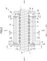
- FIG. 2 is a cross-sectional view of the ball screw device according to the embodiment.
- a ball screw device 100 As illustrated in FIGS. 1 and 2 , a ball screw device 100 according to the embodiment includes a screw shaft 1, a nut 2, a plurality of balls 12, and a coolant flow path 4.
- the screw shaft 1 extends in the X direction (axial direction) of a central axis AX.
- An outer circumferential track groove 11 is provided on an outer circumferential portion of the screw shaft 1.
- the outer circumferential track groove 11 extends spirally.
- the nut 2 includes a nut body 20, a seal member 5, and caps 30 and 31.
- the nut body 20 includes a cylindrical portion 21 and a flange portion 22.
- the cylindrical portion 21 extends in the X direction (axial direction) of the central axis AX.
- An inner circumferential track groove 222 is provided on an inner circumferential portion of the cylindrical portion 21.
- the screw shaft 1 penetrates through the inner circumferential portion of the cylindrical portion 21.
- the inner circumferential track groove 222 extends spirally.
- the plurality of balls 12 are arranged between the inner circumferential track groove 222 and the outer circumferential track groove 11.
- the cylindrical portion 21 has a cylindrical surface 211 on an outer circumferential portion thereof.
- the cylindrical portion 21 and the cylindrical surface 211 extend in a circumferential direction around the central axis AX.
- the flange portion 22 is provided at an end portion on the X2 side (the other side in the axial direction) of the nut body 20.
- the flange portion 22 protrudes outward in a radial direction from the end portion on the X2 side of the nut body 20.
- the flange portion 22 has a plurality of attachment holes 221 penetrating in the axial direction.
- the coolant flow path 4 is formed inside the nut 2.
- a coolant 40 flows inside the coolant flow path 4.
- the coolant flow path 4 includes, for example, an inlet 401 provided in the flange portion 22, a first axial flow path (axial flow path) 43 and a second axial flow path (axial flow path) 45 provided in the nut body 20.
- a first end surface 23 is provided at each of one end portion (axial end portion) 24 in the axial direction and the other end portion (axial end portion) 25 in the axial direction.
- the first end surface 23 extends in the radial direction orthogonal to (intersecting) the axial direction.
- the cap 30 has a central hole 301 at the center in the radial direction, and has a plurality of bolt holes 302 provided in the circumferential direction.
- the cap 30 has an annular shape.
- a bolt BL passes through the bolt hole 302 of the cap 30 and is fastened to the tap hole 232.
- the cap 30 is attached to the one end portion (axial end portion) 24 in the axial direction in a state of covering the first end surface 23, and seals the recessed groove 26.
- the inlet 401 is provided on the Z1 side in the flange portion 22, and an outlet 402 is provided at a middle point between the Z1 side and the Y1 side.
- the coolant 40 flows into the coolant flow path 4 from the inlet 401 and then flows out from the outlet 402.
- first seal members (seal members) 51 are provided at the one end portion (axial end portion) 24 of the nut body 20 in the axial direction.
- one first seal member 51 extends in the circumferential direction from the Z1 side to the Y2 side on the first end surface 23.
- the one first seal member 51 overlaps a first circumferential flow path (circumferential flow path) 42 when viewed from the axial direction.
- the first circumferential flow path 42 extends in the circumferential direction of the nut body 20.
- the first circumferential flow path 42 extends in the circumferential direction of the nut body 20 from a flow path end portion 421 to a flow path end portion 422.
- the other first seal member 51 extends in the circumferential direction from the Y1 side to the Z2 side on the first end surface 23.
- the other first seal member 51 overlaps a third circumferential flow path (circumferential flow path) 46 when viewed from the axial direction.
- the third circumferential flow path 46 extends in the circumferential direction of the nut body 20 from a flow path end portion 461 to a flow path end portion 462.
- the first seal member (seal member) 51 and a second seal member (seal member) 52 are provided at the other end portion (axial end portion) 25 of the nut body 20 in the axial direction.
- the first seal member 51 extends in the circumferential direction from the Y2 side to the Z2 side on the first end surface 23.
- the first seal member 51 overlaps a second circumferential flow path (circumferential flow path) 44 when viewed from the axial direction.
- the second circumferential flow path 44 extends in the circumferential direction of the nut body 20 from a flow path end portion 441 to a flow path end portion 442.
- the second seal member 52 extends in the circumferential direction from the middle point between the Z1 side and the Y1 side to the Y1 side on the first end surface 23.
- the second seal member 52 overlaps a fourth circumferential flow path (circumferential flow path) 48 when viewed from the axial direction.
- the fourth circumferential flow path 48 extends in the circumferential direction of the nut body 20 from a flow path end portion 481 to a flow path end portion 482.
- the recessed groove 26 is provided at each of the one end portion (axial end portion) 24 and the other end portion (axial end portion) 25 of the nut body 20 in the axial direction.
- the recessed groove 26 provided at the one end portion 24 in the axial direction will be described, but the recessed groove 26 provided at the other end portion 25 has a similar configuration.
- the recessed groove 26 includes a first groove 261 and a second groove 262.
- the first groove 261 is recessed from the first end surface 23 toward the X2 side (axial center side).
- the first groove 261 faces inner walls 261a and 261b and first bottom surfaces 261c and 261d.
- the inner walls 261a and 261b are orthogonal to (intersect) the first end surface 23 and extend toward the X2 side.
- the inner wall 261a and the inner wall 261b face each other in the radial direction.
- the first bottom surfaces 261c and 261d extend along the first end surface 23.
- the first bottom surface 261c extends from an end on the X2 side of the inner wall 261a toward the Z2 side.
- the first bottom surface 261d extends from an end on the X2 side of the inner wall 261b toward the Z1 side.
- a width of the first groove 261 in the radial direction is a width W10.
- the second groove 262 is recessed from the first bottom surfaces 261c and 261d toward the X2 side (axial center side).
- the second groove 262 communicates with the first groove 261.
- the second groove 262 faces inner walls 262a and 262b and a second bottom surface 262c.
- the inner walls 262a and 262b are orthogonal to (intersect) the first end surface 23 and extend toward the X2 side.
- the inner wall 262a and the inner wall 262b face each other in the radial direction.
- the second bottom surface 262c extends along the first end surface 23.
- the second bottom surface 262c connects an end on the X2 side of the inner wall 262a and an end on the X2 side of the inner wall 262b.
- Each of the first groove 261 and the second groove 262 has a rectangular cross section as indicated by a two-dot chain line.
- a width of the second groove 262 in the radial direction is a width W20.
- the width W10 is larger than the width W20. Therefore, the first bottom surfaces 261c and 261d are exposed when the recessed groove 26 is viewed from the axial direction.
- the first groove 261 and the second groove 262 communicate with the third axial flow path 47. That is, as illustrated in FIGS. 6 and 7 , the third circumferential flow path (circumferential flow path) 46 is formed by the first groove 261 and the second groove 262.
- the first circumferential flow path 42, the second circumferential flow path 44, and the fourth circumferential flow path 48, which are other circumferential flow paths, are also formed by the first groove 261 and the second groove 262.
- the first seal member (seal member) 51 is fitted into the first groove 261. Specifically, the first seal member (seal member) 51 is accommodated in the first groove 261 in a state of being in contact with the inner walls 261a and 261b, the first bottom surfaces 261c and 261d, and a back surface 30a of the cap 30. Accordingly, the recessed groove 26 is sealed by the cap 30.
- the outer circumferential portion 513 is positioned on an outer side of the nut body 20 in the radial direction with respect to the inner circumferential portion 514. Circumferential end portions of the outer circumferential portion 513 and circumferential end portions of the inner circumferential portion 514 are connected via the side end portions 515 and 516. A first portion 513a of the outer circumferential portion 513 and a second portion 514a of the inner circumferential portion 514 are connected via the reinforcing portion 512. The reinforcing portion 512 extends in the radial direction of the nut body 20. The reinforcing portion 512 is positioned between the two side end portions 515 and 516.
- the first seal member 51 is a prism having a square cross-sectional shape. Specifically, all of the frame body 511 and the reinforcing portion 512 are prisms having a square cross-sectional shape. Therefore, for example, as illustrated in FIG. 6 , three side surfaces of the outer circumferential portion 513 of the first seal member 51 are in surface contact with the inner wall 261b and the first bottom surface 261d in the first groove 261, and the back surface 30a of the cap 30. Three side surfaces of the inner circumferential portion 514 of the first seal member 51 are in surface contact with the inner wall 261a and the first bottom surface 261c in the first groove 261, and the back surface 30a of the cap 30. As illustrated in FIG.
- an inner circumferential surface of the outer circumferential portion 513 of the first seal member 51 is flush with the inner wall 262b of the second groove 262, and an inner circumferential surface of the inner circumferential portion 514 of the first seal member 51 is flush with the inner wall 262a of the second groove 262.
- the second seal member (seal member) 52 includes a frame body 521 and a reinforcing portion 522 when viewed in the axial direction.
- a length of the second seal member 52 in the circumferential direction is smaller than a length of the first seal member 51 in the circumferential direction.
- the frame body 521 extends in an arc shape in the circumferential direction of the nut body 20.
- the frame body 521 has an outer circumferential portion 523, an inner circumferential portion 524, side end portions 525 and 526, and a reinforcing portion 522.
- a first portion 523a of the outer circumferential portion 523 and a second portion 524a of the inner circumferential portion 524 are connected via the reinforcing portion 522.
- the reinforcing portion 522 is provided at the centers of the two side end portions 525 and 526 in the circumferential direction.
- the second seal member 52 has two opening portions 527 and 528. Widths of the outer circumferential portion 523, the inner circumferential portion 524, and the side end portions 525 and 526 are a width W3.
- a width of the reinforcing portion 522 is a width W4.
- the width W4 is the same as or larger than the width W3. That is, the width W4 is equal to or larger than the width W3.
- a third seal member (seal member) 53 includes a frame body 531 and reinforcing portions 532 and 533 when viewed in the axial direction.
- a length of the third seal member 53 in the circumferential direction is larger than the length of the first seal member 51 in the circumferential direction.
- the frame body 531 extends in an arc shape in the circumferential direction of the nut body 20.
- the frame body 531 has an outer circumferential portion 534, an inner circumferential portion 535, side end portions 536 and 537, and reinforcing portions 532 and 533.
- a first portion 534a of the outer circumferential portion 534 and a second portion 535a of the inner circumferential portion 535 are connected via the reinforcing portion 532.
- a first portion 534b of the outer circumferential portion 534 and a second portion 535b of the inner circumferential portion 535 are connected via the reinforcing portion 533.
- the reinforcing portion 532 and the reinforcing portion 533 are arranged at equal intervals in the circumferential direction between the side end portion 536 and the side end portion 537. Therefore, lengths of opening portions 538, 539, and 540 in the circumferential direction are the same.
- positions of the reinforcing portions 532 and 533 in the circumferential direction are not limited, and the reinforcing portions 532 and 533 do not have to be arranged at equal intervals between the side end portion 536 and the side end portion 537.
- Widths of the outer circumferential portion 534, the inner circumferential portion 535, and the side end portions 536 and 537 are a width W5.
- a width of each of the reinforcing portions 532 and 533 is a width W6.
- the width W6 is the same as or larger than the width W5. That is, the width W6 is equal to or larger than the width W5.
- FIG. 12 is a schematic view illustrating a flow of the coolant in the coolant flow path in the nut.
- An axial flow path 410 includes a first axial flow path 43, a second axial flow path 45, a third axial flow path 47, and a fourth axial flow path 49.
- a circumferential flow path 420 includes the first circumferential flow path 42, the second circumferential flow path 44, the third circumferential flow path 46, and the fourth circumferential flow path 48.
- the coolant 40 flows into the first axial flow path 43 from the inlet 401 via a flow path end portion 431.
- the first axial flow path 43 has the flow path end portion 431 and a flow path end portion 432. That is, the coolant 40 flows from the flow path end portion 431 to the flow path end portion 432. Thereafter, the coolant 40 flows along the first circumferential flow path 42 from the flow path end portion 421 to the flow path end portion 422, and flows along the second axial flow path 45 from a flow path end portion 451 to a flow path end portion 452.
- the coolant 40 flows along the second circumferential flow path 44 from the flow path end portion 441 to the flow path end portion 442, flows along the third axial flow path 47 from a flow path end portion 471 to a flow path end portion 472, and flows along the third circumferential flow path 46 from the flow path end portion 461 to the flow path end portion 462.
- the coolant 40 flows along the fourth axial flow path 49 from a flow path end portion 491 to a flow path end portion 492, flows along the fourth circumferential flow path 48 from the flow path end portion 481 to the flow path end portion 482, and then flows out of the nut 2 from the outlet 402.
- the coolant 40 alternately flows through the axial flow path 410 and the circumferential flow path 420 to uniformly cool the entire nut 2.
- the ball screw device 100 includes the nut 2 having the inner circumferential track groove 222 provided on the inner circumferential portion, the screw shaft 1 penetrating through the nut 2 and in which the outer circumferential track groove 11 is provided on the outer circumferential portion, the plurality of balls 12 arranged between the inner circumferential track groove 222 and the outer circumferential track groove 11, and the coolant flow path 4 provided inside the nut 2 and through which the coolant 40 flows.
- the nut 2 includes the nut body 20 in which the inner circumferential track groove 222 is provided and the recessed groove 26 is provided on the first end surface 23 extending in the radial direction at each of the one end portion (axial end portion) 24 in the axial direction and the other end portion (axial end portion) 25 in the axial direction, the first seal member (seal member) 51 fitted into a part of the recessed groove 26, and the annular cap 31 attached to the axial end portion in a state of covering the first end surface 23, and sealing the recessed groove 26.
- the recessed groove 26 is a recess recessed from the first end surface 23 toward the axial center side, and includes the first groove 261 facing the inner walls 261a and 261b and the first bottom surfaces (bottom portions) 261c and 261d extending along the first end surface 23 from the end portions of the inner walls 261a and 261b on the axial center side, and the second groove 262 recessed from the first bottom surfaces (bottom portions) 261c and 261d toward the axial center side.
- the coolant flow path 4 includes a plurality of axial flow paths 410 provided in the nut body 20 and extending in the axial direction, and the circumferential flow path 420 connecting axial end portions of two axial flow paths 410 among the plurality of axial flow paths 410 and extending in the circumferential direction of the nut body 20, and the circumferential flow path 420 is formed by sealing the recessed groove 26 of the nut body 20 with the cap 31.
- the first seal member (seal member) 51 includes the annular frame body 511 and the reinforcing portion 512 crossing the opening portion inside the frame body 511 when viewed from the axial direction, the frame body 511 has the outer circumferential portion (long side) 513 and the inner circumferential portion (long side) 514 extending in an arc shape along the inner walls 261a and 261b of the first groove 261, and two side end portions 515 and 516 connecting the circumferential end portion of the outer circumferential portion 513 and the circumferential end portion of the inner circumferential portion 514, and the reinforcing portion 512 is positioned between the two side end portions 515 and 516 and connects the outer circumferential portion 513 and the inner circumferential portion 514.
- the seal member has an arc shape extending in the circumferential direction of the nut when viewed from the axial direction of the nut. Therefore, for example, when the sealing member is fastened to the axial end portion of the nut with a bolt, the seal member receives a force in the circumferential direction or the radial direction when the bolt is fastened. In addition, in a case where thermal deformation occurs at the axial end portion of the nut during use of the ball screw device, a force is applied to the seal member in the circumferential direction or the radial direction. In these cases, the seal member may be deformed, as a result of which, sealability achieved by the seal member may be deteriorated.
- the first seal member (seal member) 51 includes the annular frame body 511 and the reinforcing portion 512 that connects two long sides (the outer circumferential portion 513 and the inner circumferential portion 514) of the frame body 511. Therefore, rigidity becomes higher than that of the seal member without the reinforcing portion 512, and a deformation amount becomes smaller when a force is applied in the circumferential direction or the radial direction of the nut 2. As a result, it is possible to provide the ball screw device 100 including the first seal member 51 whose deformation amount is smaller when attached to the nut 2 or during use of the ball screw device 100.
- the second seal member (seal member) 52 includes the annular frame body 521 and the reinforcing portion 522 that connects the long sides (the outer circumferential portion 523 and the inner circumferential portion 524) of the frame body 521 when viewed from the axial direction.
- the second seal member 52 has a smaller length in the circumferential direction on the first end surface 23 than the first seal member 51.
- the first seal member 51 has a length of 1/4 of the entire circumference of the first end surface 23 in the circumferential direction
- the second seal member 52 has a length of 1/8 of the entire circumference of the first end surface 23 in the circumferential direction.
- the third seal member (seal member) 53 includes the annular frame body 531 and the reinforcing portions 532 and 533 connecting the long sides (the outer circumferential portion 534 and the inner circumferential portion 535) of the frame body 531 when viewed from the axial direction.
- the plurality of reinforcing portions 532 and 533 are provided, and the plurality of reinforcing portions 532 and 533 are arranged at equal intervals in the circumferential direction between the two side end portions.
- the rigidity of the entire third seal member 53 is more uniform as compared with a seal member in which the plurality of reinforcing portions 532 and 533 are arranged at unequal intervals in the circumferential direction. Since a force on the third seal member 53 may be input from various directions such as the circumferential direction and the radial direction, the deformation amount becomes smaller when the third seal member 53 receives a force in the circumferential direction or the radial direction.
- One reinforcing portion 512 is provided in the first seal member 51, one reinforcing portion 512 is provided in the second seal member 52, the reinforcing portion 512 connects the center of the outer circumferential portion 513 in the circumferential direction and the center of the inner circumferential portion 514 in the circumferential direction, and the reinforcing portion 522 connects the center of the outer circumferential portion 523 in the circumferential direction and the center of the inner circumferential portion 524 in the circumferential direction.
- the rigidity of the entire first seal member 51 and the rigidity of the entire second seal member 52 become more uniform as compared with a case where portions other than the centers of the outer circumferential portions 513 and 523 in the circumferential direction and portions other than the center of the inner circumferential portions 514 and 524 in the circumferential direction are connected by the reinforcing portions 512 and 522. Since a force on the first seal member 51 and the second seal member 52 may be input from various directions such as the circumferential direction and the radial direction, the deformation amount becomes smaller when the first seal member 51 and the second seal member 52 receive a force in the circumferential direction or the radial direction.
- the frame body 511 and the reinforcing portion 512 of the first seal member 51 are prismatic bodies having a quadrangular cross section, and three side surfaces of the prismatic bodies are in surface contact with the inner walls 261a and 261b and the first bottom surfaces 261c and 261d in the first groove 261, and the back surface 30a of the cap 30. Accordingly, the first seal member 51 can be stably arranged between the inner walls 261a and 261b, the first bottom surfaces 261c and 261d, and the back surface 30a of the cap 30.
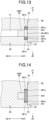
- FIG. 13 is a cross-sectional view of a part of the ball screw device according to the first modification, and is a view corresponding to FIG. 6 .
- FIG. 14 is a cross-sectional view of a part of the ball screw device according to the first modification, and is a view corresponding to FIG. 7 .
- FIG. 15 is a plan view of a seal member according to the first modification.
- a fourth seal member (seal member) 54 having a circular cross-sectional shape is applied. Details will be described below.
- the fourth seal member (seal member) 54 includes a frame body 541 and a reinforcing portion 542 when viewed in the axial direction.
- the frame body 541 extends in an arc shape in the circumferential direction of the nut body 20 when viewed from the axial direction of the nut 2.
- the frame body 541 has an outer circumferential portion 543, an inner circumferential portion 544, side end portions 545 and 546, and a reinforcing portion 542.
- the outer circumferential portion 543 and the inner circumferential portion 544 extend in an arc shape.
- the outer circumferential portion 543 is positioned on an outer side of the nut body 20 in the radial direction with respect to the inner circumferential portion 544.
- Circumferential end portions of the outer circumferential portion 543 and circumferential end portions of the inner circumferential portion 544 are connected via the side end portions 545 and 546.
- a first portion 543a of the outer circumferential portion 543 and a second portion 544a of the inner circumferential portion 544 are connected via the reinforcing portion 542.
- the reinforcing portion 542 extends in the radial direction of the nut body 20.
- the reinforcing portion 542 is positioned between the two side end portions 545 and 546.
- the reinforcing portion 542 is provided at the centers of the two side end portions 545 and 546 in the circumferential direction.
- the reinforcing portion 542 crosses one opening portion formed by the frame body 541.
- the fourth seal member 54 has two opening portions 547 and 548. Widths of the outer circumferential portion 543, the inner circumferential portion 544, and the side end portions 545 and 546 are all the same width W7. A width of the reinforcing portion 542 is a width W8. The width W7 is the same as or larger than the width W8. That is, the width W7 is equal to or larger than the width W8.
- all of the frame body 541 and the reinforcing portion 542 are cylindrical bodies having a circular cross section, and outer surfaces of the cylindrical bodies are in line contact with the inner walls 261a and 261b and the first bottom surfaces 261c and 261d in the first groove 261, and the back surface 30a of the cap 30. That is, as illustrated in FIG. 13 , the outer circumferential portion 543 of the fourth seal member 54 is in line contact with an inner wall 264a and a fourth bottom surface 264c in a fourth groove 264, and the back surface 30a of the cap 30. The inner circumferential portion 544 of the fourth seal member 54 is in line contact with an inner wall 264b and a fourth bottom surface 264d in the fourth groove 264, and the back surface 30a of the cap 30.
- all of the frame body 541 and the reinforcing portion 542 are cylindrical bodies having a circular cross section. Accordingly, the outer surface of the fourth seal member 54 uniformly contacts the inner walls 261a and 261b, the first bottom surfaces 261c and 261d, and the back surface 30a of the cap 31, so that the airtightness achieved by the fourth seal member 54 is more reliably ensured.
- a part of the fourth seal member 54 may be a cylindrical body having a circular cross section.
- FIG. 16 is a cross-sectional view of a part of the ball screw device according to the second modification, and is a view corresponding to FIG. 6 .
- FIG. 17 is a cross-sectional view of a part of the ball screw device according to the second modification, and is a view corresponding to FIG. 7 .
- FIG. 18 is a plan view of a seal member according to the second modification.
- a fifth seal member (seal member) 55 having a regular hexagonal cross-sectional shape is applied. Details will be described below.
- the fifth seal member (seal member) 55 includes a frame body 551 and a reinforcing portion 552 when viewed in the axial direction.
- the frame body 551 extends in an arc shape in the circumferential direction of the nut body 20.
- the frame body 551 has an outer circumferential portion 553, an inner circumferential portion 554, side end portions 555 and 556, and a reinforcing portion 552.
- the outer circumferential portion 553 and the inner circumferential portion 554 extend in an arc shape.
- the outer circumferential portion 553 is positioned on an outer side of the nut body 20 in the radial direction with respect to the inner circumferential portion 554.
- Circumferential end portions of the outer circumferential portion 553 and circumferential end portions of the inner circumferential portion 554 are connected via the side end portions 555 and 556.
- a first portion 553a of the outer circumferential portion 553 and a second portion 554a of the inner circumferential portion 554 are connected via the reinforcing portion 552.
- the reinforcing portion 552 extends in the radial direction of the nut body 20.
- the reinforcing portion 552 is positioned between the two side end portions 555 and 556.
- the reinforcing portion 552 is provided at the centers of the two side end portions 555 and 556 in the circumferential direction.
- the reinforcing portion 552 crosses one opening portion formed by the frame body 551.
- the fifth seal member 55 has two opening portions 557 and 558. Widths of the outer circumferential portion 553, the inner circumferential portion 554, and the side end portions 555 and 556 are all the same width W9. A width of the reinforcing portion 552 is a width W10. The width W9 is the same as the width W10 or larger than the width W9. That is, the width W9 is equal to or larger than the width W10.
- the fifth seal member 55 is a prismatic body having a regular hexagonal cross section.
- the frame body 551 and the reinforcing portion 552 are prismatic bodies having a regular hexagonal cross section.
- one side surface of the outer circumferential portion 553 of the fifth seal member 55 is in surface contact with the inner wall 261b of the first groove 261.
- One side surface of the inner circumferential portion 554 of the fifth seal member 55 is in surface contact with the inner wall 261a of the first groove 261. Accordingly, airtightness achieved by the fifth seal member 55 is improved.
Landscapes
- Engineering & Computer Science (AREA)
- General Engineering & Computer Science (AREA)
- Mechanical Engineering (AREA)
- Transmission Devices (AREA)
- Gasket Seals (AREA)
Abstract
Description
- The present disclosure relates to a ball screw device.
- A ball screw device includes, for example, a nut having an inner circumferential track groove, a screw shaft penetrating through the nut and having an outer circumferential track groove, a plurality of balls arranged between the inner circumferential track groove and the outer circumferential track groove, and a coolant flow path provided inside the nut and through which a coolant flows (see Patent Literature 1). The coolant flow path includes an axial flow path extending in an axial direction of the nut and a circumferential flow path extending in a circumferential direction of the nut. The circumferential flow path is formed by a circumferential groove formed at an axial end portion of the nut and opened to the outside in the axial direction, a seal member fitted to an end portion of an inner wall of the circumferential groove to seal the circumferential groove, and a sealing member that is in contact with the seal member to seal the circumferential groove. When viewed from the axial direction of the nut, the seal member has an annular shape extending in the circumferential direction of the nut.
- Patent Literature 1:
JP 3217729 U - In
Patent Literature 1, for example, in a case where the sealing member is bolted to the axial end portion of the nut, the seal member receives a force in the circumferential direction or a radial direction when a bolt is fastened. In addition, in a case where thermal deformation occurs at the axial end portion of the nut during use of the ball screw device, a force is applied to the seal member in the circumferential direction or the radial direction. In these cases, the seal member may be deformed, as a result of which, airtightness of the circumferential groove may be reduced. - The present disclosure has been made in view of the above-described problems, and an object of the present disclosure is to provide a ball screw device including a seal member whose deformation amount is smaller when attached to a nut or during use of the ball screw device. Solution to Problem
- To achieve the above object, a ball screw device according to an embodiment comprising:
- a nut having an inner circumferential track groove provided on an inner circumferential portion and including a plurality of axial flow paths through which a coolant flows in an axial direction;
- a screw shaft penetrating through the nut and having an outer circumferential track groove provided on an outer circumferential portion; and
- a plurality of balls arranged between the inner circumferential track groove and the outer circumferential track groove, wherein
- the nut includes:
- a nut body in which a recessed groove is provided on a first end surface arranged at at least one axial end portion of one end portion or the other end portion in the axial direction along a central axis;
- a seal member fitted into the recessed groove; and
- a cap attached to the axial end portion in a state of covering the recessed groove of the first end surface, and closing a circumferential flow path in which the coolant flows in a circumferential direction in the recessed groove communicating between end portions of two of the plurality of axial flow paths,
- the recessed groove includes:
- a first groove which is a recess recessed from the first end surface toward an axial center side and into which the seal member is fitted, the recess having an outer shape extending in the circumferential direction of the nut when viewed from the axial direction of the nut; and
- a second groove which is provided inside the first groove when viewed in the axial direction of the nut, which is recessed from a bottom portion of the first groove toward the axial center side, and in which the end portions of the two axial flow paths are exposed, and
- the seal member includes:
- a frame body extending along the first groove; and
- a reinforcing portion connecting a pair of long sides of the frame body.
- In the ball screw of
Patent Literature 1 described above, the seal member has an arc shape extending in the circumferential direction of the nut when viewed from the axial direction of the nut. Therefore, for example, when the sealing member is fastened to the axial end portion of the nut with a bolt, the seal member receives a force in the circumferential direction or the radial direction when the bolt is fastened. In addition, in a case where the axial end portion of the nut is thermally deformed during use of the ball screw device, a force is applied to the seal member in the circumferential direction or the radial direction. In these cases, the seal member may be deformed, as a result of which, airtightness of the circumferential groove may be reduced. - On the other hand, the seal member according to the present disclosure includes the frame body and the reinforcing portion connecting a pair of long sides of the frame body. Therefore, rigidity becomes higher than that of the seal member without the reinforcing portion, and a deformation amount becomes smaller when a force is applied in the circumferential direction or the radial direction. As a result, it is possible to provide the ball screw device including the seal member whose deformation amount is smaller when attached to the nut or during use of the ball screw device.
- As a desirable embodiment, one reinforcing portion is provided, and the one reinforcing portion connects centers of the pair of long sides in the circumferential direction.
- Therefore, the rigidity of the entire seal member becomes more uniform as compared with a case where portions other than the centers of the pair of long sides in the circumferential direction are connected to each other by the reinforcing portion. Since a force on the seal member may be input from various directions such as the circumferential direction and the radial direction, the deformation amount becomes smaller when the seal member receives a force in various directions such as the circumferential direction and the radial direction.
- As a desirable embodiment, a plurality of the reinforcing portions are provided, and the plurality of reinforcing portions are arranged at equal intervals in the circumferential direction. Therefore, the rigidity of the entire seal member becomes more uniform as compared with a case where a plurality of reinforcing portions are arranged at unequal intervals in the circumferential direction. Since a force on the seal member may be input from various directions such as the circumferential direction and the radial direction of the nut, the deformation amount of the seal member becomes smaller.
- As a desirable embodiment, the first groove faces an inner wall extending from the first end surface to the axial center side and a bottom portion extending from an end portion of the inner wall on the axial center side along the first end surface, and the seal member includes a cylindrical body having a circular cross section, and an outer surface of the cylindrical body is in line contact with the inner wall and the bottom portion in the first groove, and a back surface of the cap. With such a configuration, an outer surface of the seal member is uniformly brought into contact with the inner wall, the first bottom surface, and the back surface of the cap, and thus, airtightness achieved by the seal member is more reliably ensured.
- As a desirable embodiment, the first groove faces an inner wall extending from the first end surface to the axial center side and a bottom portion extending from an end portion of the inner wall on the axial center side along the first end surface, and the seal member includes a prismatic body having a polygonal cross-sectional shape. With such a configuration, the polygon has at least one plane, and thus, the plane can be brought into surface contact with any one of the inner wall in the first groove, the first bottom surface, and the back surface of the cap. Therefore, the seal member can be stably attached to the nut.
- As a desirable embodiment, the seal member includes a prismatic body having a quadrangular cross section, and three side surfaces of the prismatic body are in surface contact with the inner wall and the bottom portion in the first groove, and the back surface of the cap. As a result, the seal member can be stably arranged between the inner wall, the first bottom surface, and the back surface of the cap.
- As a desirable embodiment, the seal member includes a prismatic body having a regular hexagonal cross section, and one side surface of the prismatic body is in surface contact with the inner wall in the first groove. Therefore, the seal member can be stably attached to the nut.
- According to the present disclosure, it is possible to provide a ball screw device including a seal member whose deformation amount is smaller when attached to a nut or during use of the ball screw device.
-
-
FIG. 1 is an exploded perspective view of a ball screw device according to an embodiment. -
FIG. 2 is a cross-sectional view of the ball screw device according to the embodiment. -
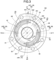
FIG. 3 is a cross-sectional view taken along line III-III ofFIG. 2 . -
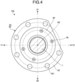
FIG. 4 is a cross-sectional view taken along line IV-IV ofFIG. 2 . -
FIG. 5 is a view illustrating a state in which a cap is removed fromFIG. 4 . -
FIG. 6 is a cross-sectional view taken along line VI-VI ofFIG. 3 . -
FIG. 7 is a cross-sectional view taken along line VII-VII ofFIG. 3 . -
FIG. 8 is a cross-sectional view in which a seal member and the cap are removed fromFIG. 7 . -
FIG. 9 is a plan view of the seal member illustrated inFIGS. 3 and5 . -
FIG. 10 is a plan view of the seal member illustrated inFIG. 5 . -
FIG. 11 is a schematic plan view illustrating another example of the seal member. -
FIG. 12 is a schematic view illustrating a flow of a coolant in a coolant flow path in a nut. -
FIG. 13 is a cross-sectional view of a part of the ball screw device according to a first modification, and is a view corresponding toFIG. 6 . -
FIG. 14 is a cross-sectional view of a part of the ball screw device according to the first modification, and is a view corresponding toFIG. 7 . -
FIG. 15 is a plan view of a seal member according to the first modification. -
FIG. 16 is a cross-sectional view of a part of the ball screw device according to a second modification, and is a view corresponding toFIG. 6 . -
FIG. 17 is a cross-sectional view of a part of the ball screw device according to the second modification, and is a view corresponding toFIG. 7 . -
FIG. 18 is a plan view of a seal member according to the second modification. - A mode (embodiment) for carrying out the present invention will be described in detail with reference to the drawings. The present invention is not limited by the contents described in the following embodiments. In addition, constituent elements described below include those that can be easily assumed by those skilled in the art and those that are substantially the same. Furthermore, the constituent elements described below can be appropriately combined. Furthermore, portions having the same structure are denoted by the same reference numerals, and a description thereof will be omitted. An X direction indicates an axial direction, and a Y direction and a Z direction indicate a radial direction. The Y direction and the Z direction are orthogonal to (intersect) the X direction. The Y direction is orthogonal to (intersects) the Z direction. An Xl side indicates one side in the axial direction, and an X2 side indicates the other side in the axial direction. A Y1 side is opposite to a Y2 side, and a Z1 side is opposite to a Z2 side.
- Hereinafter, embodiments will be described.
FIG. 1 is an exploded perspective view of a ball screw device according to an embodiment.FIG. 2 is a cross-sectional view of the ball screw device according to the embodiment. - As illustrated in
FIGS. 1 and2 , aball screw device 100 according to the embodiment includes ascrew shaft 1, anut 2, a plurality ofballs 12, and acoolant flow path 4. - The
screw shaft 1 extends in the X direction (axial direction) of a central axis AX. An outercircumferential track groove 11 is provided on an outer circumferential portion of thescrew shaft 1. The outercircumferential track groove 11 extends spirally. - The
nut 2 includes anut body 20, aseal member 5, and caps 30 and 31. Thenut body 20 includes acylindrical portion 21 and aflange portion 22. - The
cylindrical portion 21 extends in the X direction (axial direction) of the central axis AX. An innercircumferential track groove 222 is provided on an inner circumferential portion of thecylindrical portion 21. Thescrew shaft 1 penetrates through the inner circumferential portion of thecylindrical portion 21. The innercircumferential track groove 222 extends spirally. The plurality ofballs 12 are arranged between the innercircumferential track groove 222 and the outercircumferential track groove 11. Thecylindrical portion 21 has acylindrical surface 211 on an outer circumferential portion thereof. Thecylindrical portion 21 and thecylindrical surface 211 extend in a circumferential direction around the central axis AX. Theflange portion 22 is provided at an end portion on the X2 side (the other side in the axial direction) of thenut body 20. That is, theflange portion 22 protrudes outward in a radial direction from the end portion on the X2 side of thenut body 20. Theflange portion 22 has a plurality of attachment holes 221 penetrating in the axial direction. - The
coolant flow path 4 is formed inside thenut 2. Acoolant 40 flows inside thecoolant flow path 4. As illustrated inFIG. 2 , thecoolant flow path 4 includes, for example, aninlet 401 provided in theflange portion 22, a first axial flow path (axial flow path) 43 and a second axial flow path (axial flow path) 45 provided in thenut body 20. In thenut body 20, afirst end surface 23 is provided at each of one end portion (axial end portion) 24 in the axial direction and the other end portion (axial end portion) 25 in the axial direction. Thefirst end surface 23 extends in the radial direction orthogonal to (intersecting) the axial direction.FIG. 1 illustrates thefirst end surface 23 provided at the one end portion (axial end portion) 24 in the axial direction. A recessedgroove 26 and atap hole 232 are formed in thefirst end surface 23. Theseal member 5 is fitted into the recessedgroove 26. Thecap 30 has acentral hole 301 at the center in the radial direction, and has a plurality of bolt holes 302 provided in the circumferential direction. Thecap 30 has an annular shape. A bolt BL passes through thebolt hole 302 of thecap 30 and is fastened to thetap hole 232. As a result, thecap 30 is attached to the one end portion (axial end portion) 24 in the axial direction in a state of covering thefirst end surface 23, and seals the recessedgroove 26. -
FIG. 3 is a cross-sectional view taken along line III-III ofFIG. 2 .FIG. 4 is a cross-sectional view taken along line IV-IV inFIG. 2 .FIG. 5 is a view illustrating a state in which the cap is removed fromFIG. 4 . - As illustrated in
FIGS. 3 and5 , theinlet 401 is provided on the Z1 side in theflange portion 22, and anoutlet 402 is provided at a middle point between the Z1 side and the Y1 side. Thecoolant 40 flows into thecoolant flow path 4 from theinlet 401 and then flows out from theoutlet 402. - As illustrated in
FIG. 3 , two first seal members (seal members) 51 are provided at the one end portion (axial end portion) 24 of thenut body 20 in the axial direction. Specifically, onefirst seal member 51 extends in the circumferential direction from the Z1 side to the Y2 side on thefirst end surface 23. The onefirst seal member 51 overlaps a first circumferential flow path (circumferential flow path) 42 when viewed from the axial direction. The firstcircumferential flow path 42 extends in the circumferential direction of thenut body 20. The firstcircumferential flow path 42 extends in the circumferential direction of thenut body 20 from a flowpath end portion 421 to a flowpath end portion 422. - The other
first seal member 51 extends in the circumferential direction from the Y1 side to the Z2 side on thefirst end surface 23. The otherfirst seal member 51 overlaps a third circumferential flow path (circumferential flow path) 46 when viewed from the axial direction. The thirdcircumferential flow path 46 extends in the circumferential direction of thenut body 20 from a flowpath end portion 461 to a flowpath end portion 462. - As illustrated in
FIG. 5 , the first seal member (seal member) 51 and a second seal member (seal member) 52 are provided at the other end portion (axial end portion) 25 of thenut body 20 in the axial direction. Specifically, thefirst seal member 51 extends in the circumferential direction from the Y2 side to the Z2 side on thefirst end surface 23. Thefirst seal member 51 overlaps a second circumferential flow path (circumferential flow path) 44 when viewed from the axial direction. The secondcircumferential flow path 44 extends in the circumferential direction of thenut body 20 from a flowpath end portion 441 to a flowpath end portion 442. Thesecond seal member 52 extends in the circumferential direction from the middle point between the Z1 side and the Y1 side to the Y1 side on thefirst end surface 23. Thesecond seal member 52 overlaps a fourth circumferential flow path (circumferential flow path) 48 when viewed from the axial direction. The fourthcircumferential flow path 48 extends in the circumferential direction of thenut body 20 from a flowpath end portion 481 to a flowpath end portion 482. -
FIG. 6 is a cross-sectional view taken along line VI-VI ofFIG. 3 .FIG. 7 is a cross-sectional view taken along line VII-VII ofFIG. 3 .FIG. 8 is a cross-sectional view in which the seal member and the cap are removed fromFIG. 7 . - As illustrated in
FIG. 8 , the recessedgroove 26 is provided at each of the one end portion (axial end portion) 24 and the other end portion (axial end portion) 25 of thenut body 20 in the axial direction. Hereinafter, the recessedgroove 26 provided at the oneend portion 24 in the axial direction will be described, but the recessedgroove 26 provided at theother end portion 25 has a similar configuration. - As illustrated in
FIG. 8 , the recessedgroove 26 includes afirst groove 261 and asecond groove 262. As illustrated inFIG. 8 , thefirst groove 261 is recessed from thefirst end surface 23 toward the X2 side (axial center side). Thefirst groove 261 facesinner walls inner walls first end surface 23 and extend toward the X2 side. Theinner wall 261a and theinner wall 261b face each other in the radial direction. The first bottom surfaces 261c and 261d extend along thefirst end surface 23. Specifically, the firstbottom surface 261c extends from an end on the X2 side of theinner wall 261a toward the Z2 side. Thefirst bottom surface 261d extends from an end on the X2 side of theinner wall 261b toward the Z1 side. A width of thefirst groove 261 in the radial direction is a width W10. - As illustrated in
FIG. 8 , thesecond groove 262 is recessed from the first bottom surfaces 261c and 261d toward the X2 side (axial center side). Thesecond groove 262 communicates with thefirst groove 261. Thesecond groove 262 facesinner walls bottom surface 262c. Theinner walls first end surface 23 and extend toward the X2 side. Theinner wall 262a and theinner wall 262b face each other in the radial direction. The secondbottom surface 262c extends along thefirst end surface 23. The secondbottom surface 262c connects an end on the X2 side of theinner wall 262a and an end on the X2 side of theinner wall 262b. Each of thefirst groove 261 and thesecond groove 262 has a rectangular cross section as indicated by a two-dot chain line. A width of thesecond groove 262 in the radial direction is a width W20. The width W10 is larger than the width W20. Therefore, the first bottom surfaces 261c and 261d are exposed when the recessedgroove 26 is viewed from the axial direction. - As illustrated in
FIG. 6 , in a cross section of a portion overlapping a third axial flow path (axial flow path) 47 when viewed from the axial direction, thefirst groove 261 and thesecond groove 262 communicate with the thirdaxial flow path 47. That is, as illustrated inFIGS. 6 and 7 , the third circumferential flow path (circumferential flow path) 46 is formed by thefirst groove 261 and thesecond groove 262. The firstcircumferential flow path 42, the secondcircumferential flow path 44, and the fourthcircumferential flow path 48, which are other circumferential flow paths, are also formed by thefirst groove 261 and thesecond groove 262. - Here, the first seal member (seal member) 51 is fitted into the
first groove 261. Specifically, the first seal member (seal member) 51 is accommodated in thefirst groove 261 in a state of being in contact with theinner walls back surface 30a of thecap 30. Accordingly, the recessedgroove 26 is sealed by thecap 30. - Next, the seal member will be described.
FIG. 9 is a plan view of the seal member illustrated inFIGS. 3 and5 .FIG. 10 is a plan view of the seal member illustrated inFIG. 5 .FIG. 11 is a schematic plan view illustrating another example of the seal member. - As illustrated in
FIG. 9 , the first seal member (seal member) 51 includes aframe body 511 and a reinforcingportion 512 when viewed from the axial direction. Theframe body 511 extends in an arc shape in the circumferential direction of thenut body 20. In other words, a longitudinal direction of theframe body 511 is the circumferential direction of thenut body 20. Theframe body 511 has an outercircumferential portion 513, an innercircumferential portion 514,side end portions portion 512. The outercircumferential portion 513 and the innercircumferential portion 514 extend in an arc shape. The outercircumferential portion 513 is positioned on an outer side of thenut body 20 in the radial direction with respect to the innercircumferential portion 514. Circumferential end portions of the outercircumferential portion 513 and circumferential end portions of the innercircumferential portion 514 are connected via theside end portions first portion 513a of the outercircumferential portion 513 and asecond portion 514a of the innercircumferential portion 514 are connected via the reinforcingportion 512. The reinforcingportion 512 extends in the radial direction of thenut body 20. The reinforcingportion 512 is positioned between the twoside end portions portion 512 is provided at the centers of the twoside end portions first portion 513a is positioned at the center of the outercircumferential portion 513 in the circumferential direction, and thesecond portion 514a is positioned at the center of the innercircumferential portion 514 in the circumferential direction. The reinforcingportion 512 crosses one opening portion formed by theframe body 511. Therefore, thefirst seal member 51 has two openingportions circumferential portion 513, the innercircumferential portion 514, and theside end portions portion 512 is a width W2. The width W2 is the same as or larger than the width W1. That is, the width W2 is equal to or larger than the width W1. - The
first seal member 51 is a prism having a square cross-sectional shape. Specifically, all of theframe body 511 and the reinforcingportion 512 are prisms having a square cross-sectional shape. Therefore, for example, as illustrated inFIG. 6 , three side surfaces of the outercircumferential portion 513 of thefirst seal member 51 are in surface contact with theinner wall 261b and thefirst bottom surface 261d in thefirst groove 261, and theback surface 30a of thecap 30. Three side surfaces of the innercircumferential portion 514 of thefirst seal member 51 are in surface contact with theinner wall 261a and the firstbottom surface 261c in thefirst groove 261, and theback surface 30a of thecap 30. As illustrated inFIG. 6 , an inner circumferential surface of the outercircumferential portion 513 of thefirst seal member 51 is flush with theinner wall 262b of thesecond groove 262, and an inner circumferential surface of the innercircumferential portion 514 of thefirst seal member 51 is flush with theinner wall 262a of thesecond groove 262. - As illustrated in
FIG. 10 , the second seal member (seal member) 52 includes aframe body 521 and a reinforcingportion 522 when viewed in the axial direction. A length of thesecond seal member 52 in the circumferential direction is smaller than a length of thefirst seal member 51 in the circumferential direction. Theframe body 521 extends in an arc shape in the circumferential direction of thenut body 20. Theframe body 521 has an outercircumferential portion 523, an innercircumferential portion 524,side end portions portion 522. Afirst portion 523a of the outercircumferential portion 523 and asecond portion 524a of the innercircumferential portion 524 are connected via the reinforcingportion 522. In the present embodiment, the reinforcingportion 522 is provided at the centers of the twoside end portions second seal member 52 has two openingportions circumferential portion 523, the innercircumferential portion 524, and theside end portions portion 522 is a width W4. The width W4 is the same as or larger than the width W3. That is, the width W4 is equal to or larger than the width W3. - As illustrated in
FIG. 11 , a third seal member (seal member) 53 includes aframe body 531 and reinforcingportions third seal member 53 in the circumferential direction is larger than the length of thefirst seal member 51 in the circumferential direction. Theframe body 531 extends in an arc shape in the circumferential direction of thenut body 20. Theframe body 531 has an outercircumferential portion 534, an innercircumferential portion 535,side end portions portions first portion 534a of the outercircumferential portion 534 and asecond portion 535a of the innercircumferential portion 535 are connected via the reinforcingportion 532. Afirst portion 534b of the outercircumferential portion 534 and asecond portion 535b of the innercircumferential portion 535 are connected via the reinforcingportion 533. In the present embodiment, the reinforcingportion 532 and the reinforcingportion 533 are arranged at equal intervals in the circumferential direction between theside end portion 536 and theside end portion 537. Therefore, lengths of openingportions portions portions side end portion 536 and theside end portion 537. Widths of the outercircumferential portion 534, the innercircumferential portion 535, and theside end portions portions - Next, a flow of the coolant will be described.
FIG. 12 is a schematic view illustrating a flow of the coolant in the coolant flow path in the nut. - An
axial flow path 410 includes a firstaxial flow path 43, a secondaxial flow path 45, a thirdaxial flow path 47, and a fourthaxial flow path 49. Acircumferential flow path 420 includes the firstcircumferential flow path 42, the secondcircumferential flow path 44, the thirdcircumferential flow path 46, and the fourthcircumferential flow path 48. - First, the
coolant 40 flows into the firstaxial flow path 43 from theinlet 401 via a flowpath end portion 431. The firstaxial flow path 43 has the flowpath end portion 431 and a flowpath end portion 432. That is, thecoolant 40 flows from the flowpath end portion 431 to the flowpath end portion 432. Thereafter, thecoolant 40 flows along the firstcircumferential flow path 42 from the flowpath end portion 421 to the flowpath end portion 422, and flows along the secondaxial flow path 45 from a flowpath end portion 451 to a flowpath end portion 452. Thereafter, thecoolant 40 flows along the secondcircumferential flow path 44 from the flowpath end portion 441 to the flowpath end portion 442, flows along the thirdaxial flow path 47 from a flowpath end portion 471 to a flowpath end portion 472, and flows along the thirdcircumferential flow path 46 from the flowpath end portion 461 to the flowpath end portion 462. Then, thecoolant 40 flows along the fourthaxial flow path 49 from a flowpath end portion 491 to a flowpath end portion 492, flows along the fourthcircumferential flow path 48 from the flowpath end portion 481 to the flowpath end portion 482, and then flows out of thenut 2 from theoutlet 402. In this manner, thecoolant 40 alternately flows through theaxial flow path 410 and thecircumferential flow path 420 to uniformly cool theentire nut 2. - As described above, the
ball screw device 100 includes thenut 2 having the innercircumferential track groove 222 provided on the inner circumferential portion, thescrew shaft 1 penetrating through thenut 2 and in which the outercircumferential track groove 11 is provided on the outer circumferential portion, the plurality ofballs 12 arranged between the innercircumferential track groove 222 and the outercircumferential track groove 11, and thecoolant flow path 4 provided inside thenut 2 and through which thecoolant 40 flows. Thenut 2 includes thenut body 20 in which the innercircumferential track groove 222 is provided and the recessedgroove 26 is provided on thefirst end surface 23 extending in the radial direction at each of the one end portion (axial end portion) 24 in the axial direction and the other end portion (axial end portion) 25 in the axial direction, the first seal member (seal member) 51 fitted into a part of the recessedgroove 26, and theannular cap 31 attached to the axial end portion in a state of covering thefirst end surface 23, and sealing the recessedgroove 26. The recessedgroove 26 is a recess recessed from thefirst end surface 23 toward the axial center side, and includes thefirst groove 261 facing theinner walls first end surface 23 from the end portions of theinner walls second groove 262 recessed from the first bottom surfaces (bottom portions) 261c and 261d toward the axial center side. When viewed from the axial direction, thefirst groove 261 and thesecond groove 262 extend in the circumferential direction of thenut body 20, the width W10 of thefirst groove 261 is larger than the width W20 of thesecond groove 262, and the first seal member (seal member) 51 is fitted into thefirst groove 261. Thecoolant flow path 4 includes a plurality ofaxial flow paths 410 provided in thenut body 20 and extending in the axial direction, and thecircumferential flow path 420 connecting axial end portions of twoaxial flow paths 410 among the plurality ofaxial flow paths 410 and extending in the circumferential direction of thenut body 20, and thecircumferential flow path 420 is formed by sealing the recessedgroove 26 of thenut body 20 with thecap 31. The first seal member (seal member) 51 includes theannular frame body 511 and the reinforcingportion 512 crossing the opening portion inside theframe body 511 when viewed from the axial direction, theframe body 511 has the outer circumferential portion (long side) 513 and the inner circumferential portion (long side) 514 extending in an arc shape along theinner walls first groove 261, and twoside end portions circumferential portion 513 and the circumferential end portion of the innercircumferential portion 514, and the reinforcingportion 512 is positioned between the twoside end portions circumferential portion 513 and the innercircumferential portion 514. - In the ball screw of
Patent Literature 1 described above, the seal member has an arc shape extending in the circumferential direction of the nut when viewed from the axial direction of the nut. Therefore, for example, when the sealing member is fastened to the axial end portion of the nut with a bolt, the seal member receives a force in the circumferential direction or the radial direction when the bolt is fastened. In addition, in a case where thermal deformation occurs at the axial end portion of the nut during use of the ball screw device, a force is applied to the seal member in the circumferential direction or the radial direction. In these cases, the seal member may be deformed, as a result of which, sealability achieved by the seal member may be deteriorated. - On the other hand, the first seal member (seal member) 51 according to the present embodiment includes the
annular frame body 511 and the reinforcingportion 512 that connects two long sides (the outercircumferential portion 513 and the inner circumferential portion 514) of theframe body 511. Therefore, rigidity becomes higher than that of the seal member without the reinforcingportion 512, and a deformation amount becomes smaller when a force is applied in the circumferential direction or the radial direction of thenut 2. As a result, it is possible to provide theball screw device 100 including thefirst seal member 51 whose deformation amount is smaller when attached to thenut 2 or during use of theball screw device 100. - In addition, the second seal member (seal member) 52 includes the
annular frame body 521 and the reinforcingportion 522 that connects the long sides (the outercircumferential portion 523 and the inner circumferential portion 524) of theframe body 521 when viewed from the axial direction. - The
second seal member 52 has a smaller length in the circumferential direction on thefirst end surface 23 than thefirst seal member 51. Specifically, thefirst seal member 51 has a length of 1/4 of the entire circumference of thefirst end surface 23 in the circumferential direction, whereas thesecond seal member 52 has a length of 1/8 of the entire circumference of thefirst end surface 23 in the circumferential direction. As described above, even in thesecond seal member 52 having a length smaller than that of thefirst seal member 51 in the circumferential direction, the reinforcingportion 522 connecting the outercircumferential portion 523 and the innercircumferential portion 524 is provided, so that the rigidity becomes higher than that of the seal member without the reinforcingportion 522, and the deformation amount becomes smaller when a force is applied in the circumferential direction or the radial direction. - The third seal member (seal member) 53 includes the
annular frame body 531 and the reinforcingportions circumferential portion 534 and the inner circumferential portion 535) of theframe body 531 when viewed from the axial direction. The plurality of reinforcingportions portions - Therefore, the rigidity of the entire
third seal member 53 is more uniform as compared with a seal member in which the plurality of reinforcingportions third seal member 53 may be input from various directions such as the circumferential direction and the radial direction, the deformation amount becomes smaller when thethird seal member 53 receives a force in the circumferential direction or the radial direction. - One reinforcing
portion 512 is provided in thefirst seal member 51, one reinforcingportion 512 is provided in thesecond seal member 52, the reinforcingportion 512 connects the center of the outercircumferential portion 513 in the circumferential direction and the center of the innercircumferential portion 514 in the circumferential direction, and the reinforcingportion 522 connects the center of the outercircumferential portion 523 in the circumferential direction and the center of the innercircumferential portion 524 in the circumferential direction. Therefore, the rigidity of the entirefirst seal member 51 and the rigidity of the entiresecond seal member 52 become more uniform as compared with a case where portions other than the centers of the outercircumferential portions circumferential portions portions first seal member 51 and thesecond seal member 52 may be input from various directions such as the circumferential direction and the radial direction, the deformation amount becomes smaller when thefirst seal member 51 and thesecond seal member 52 receive a force in the circumferential direction or the radial direction. - Further, the
frame body 511 and the reinforcingportion 512 of thefirst seal member 51 are prismatic bodies having a quadrangular cross section, and three side surfaces of the prismatic bodies are in surface contact with theinner walls first groove 261, and theback surface 30a of thecap 30. Accordingly, thefirst seal member 51 can be stably arranged between theinner walls back surface 30a of thecap 30. - Hereinafter, a first modification will be described.
FIG. 13 is a cross-sectional view of a part of the ball screw device according to the first modification, and is a view corresponding toFIG. 6 .FIG. 14 is a cross-sectional view of a part of the ball screw device according to the first modification, and is a view corresponding toFIG. 7 .FIG. 15 is a plan view of a seal member according to the first modification. - In the first modification, as illustrated in
FIGS. 13 and 14 , a fourth seal member (seal member) 54 having a circular cross-sectional shape is applied. Details will be described below. - As illustrated in
FIG. 15 , the fourth seal member (seal member) 54 includes aframe body 541 and a reinforcingportion 542 when viewed in the axial direction. Theframe body 541 extends in an arc shape in the circumferential direction of thenut body 20 when viewed from the axial direction of thenut 2. Theframe body 541 has an outercircumferential portion 543, an innercircumferential portion 544,side end portions portion 542. The outercircumferential portion 543 and the innercircumferential portion 544 extend in an arc shape. The outercircumferential portion 543 is positioned on an outer side of thenut body 20 in the radial direction with respect to the innercircumferential portion 544. Circumferential end portions of the outercircumferential portion 543 and circumferential end portions of the innercircumferential portion 544 are connected via theside end portions first portion 543a of the outercircumferential portion 543 and asecond portion 544a of the innercircumferential portion 544 are connected via the reinforcingportion 542. The reinforcingportion 542 extends in the radial direction of thenut body 20. The reinforcingportion 542 is positioned between the twoside end portions portion 542 is provided at the centers of the twoside end portions portion 542 crosses one opening portion formed by theframe body 541. Therefore, thefourth seal member 54 has two openingportions circumferential portion 543, the innercircumferential portion 544, and theside end portions portion 542 is a width W8. The width W7 is the same as or larger than the width W8. That is, the width W7 is equal to or larger than the width W8. - As illustrated in
FIGS. 13 and 14 , in thefourth seal member 54, all of theframe body 541 and the reinforcingportion 542 are cylindrical bodies having a circular cross section, and outer surfaces of the cylindrical bodies are in line contact with theinner walls first groove 261, and theback surface 30a of thecap 30. That is, as illustrated inFIG. 13 , the outercircumferential portion 543 of thefourth seal member 54 is in line contact with an inner wall 264a and a fourth bottom surface 264c in a fourth groove 264, and theback surface 30a of thecap 30. The innercircumferential portion 544 of thefourth seal member 54 is in line contact with an inner wall 264b and a fourth bottom surface 264d in the fourth groove 264, and theback surface 30a of thecap 30. - As described above, in the first modification, in the
fourth seal member 54, all of theframe body 541 and the reinforcingportion 542 are cylindrical bodies having a circular cross section. Accordingly, the outer surface of thefourth seal member 54 uniformly contacts theinner walls back surface 30a of thecap 31, so that the airtightness achieved by thefourth seal member 54 is more reliably ensured. A part of thefourth seal member 54 may be a cylindrical body having a circular cross section. - Hereinafter, a second modification will be described.
FIG. 16 is a cross-sectional view of a part of the ball screw device according to the second modification, and is a view corresponding toFIG. 6 .FIG. 17 is a cross-sectional view of a part of the ball screw device according to the second modification, and is a view corresponding toFIG. 7 .FIG. 18 is a plan view of a seal member according to the second modification. - In the second modification, as illustrated in
FIGS. 16 and17 , a fifth seal member (seal member) 55 having a regular hexagonal cross-sectional shape is applied. Details will be described below. - As illustrated in
FIG. 18 , the fifth seal member (seal member) 55 includes aframe body 551 and a reinforcingportion 552 when viewed in the axial direction. Theframe body 551 extends in an arc shape in the circumferential direction of thenut body 20. Theframe body 551 has an outercircumferential portion 553, an innercircumferential portion 554,side end portions portion 552. The outercircumferential portion 553 and the innercircumferential portion 554 extend in an arc shape. The outercircumferential portion 553 is positioned on an outer side of thenut body 20 in the radial direction with respect to the innercircumferential portion 554. Circumferential end portions of the outercircumferential portion 553 and circumferential end portions of the innercircumferential portion 554 are connected via theside end portions first portion 553a of the outercircumferential portion 553 and asecond portion 554a of the innercircumferential portion 554 are connected via the reinforcingportion 552. The reinforcingportion 552 extends in the radial direction of thenut body 20. The reinforcingportion 552 is positioned between the twoside end portions portion 552 is provided at the centers of the twoside end portions portion 552 crosses one opening portion formed by theframe body 551. Therefore, thefifth seal member 55 has two openingportions circumferential portion 553, the innercircumferential portion 554, and theside end portions portion 552 is a width W10. The width W9 is the same as the width W10 or larger than the width W9. That is, the width W9 is equal to or larger than the width W10. - As illustrated in
FIGS. 16 and17 , thefifth seal member 55 is a prismatic body having a regular hexagonal cross section. Specifically, theframe body 551 and the reinforcingportion 552 are prismatic bodies having a regular hexagonal cross section. - Therefore, for example, as illustrated in
FIG. 16 , one side surface of the outercircumferential portion 553 of thefifth seal member 55 is in surface contact with theinner wall 261b of thefirst groove 261. One side surface of the innercircumferential portion 554 of thefifth seal member 55 is in surface contact with theinner wall 261a of thefirst groove 261. Accordingly, airtightness achieved by thefifth seal member 55 is improved. -
- 1 SCREW SHAFT
- 11 OUTER CIRCUMFERENTIAL TRACK GROOVE
- 12 BALL
- 100 BALL SCREW DEVICE
- 2 NUT
- 20 NUT BODY
- 21 CYLINDRICAL PORTION
- 211 CYLINDRICAL SURFACE
- 22 FLANGE PORTION
- 221 ATTACHMENT HOLE
- 222 INNER CIRCUMFERENTIAL TRACK GROOVE
- 23 FIRST END SURFACE
- 232 TAP HOLE
- 24 ONE END PORTION IN AXIAL DIRECTION (AXIAL END PORTION)
- 25 THE OTHER END PORTION IN AXIAL DIRECTION (AXIAL END PORTION)
- 26 RECESSED GROOVE
- 261 FIRST GROOVE
- 261a INNER WALL
- 261b INNER WALL
- 261c FIRST BOTTOM SURFACE (BOTTOM PORTION)
- 261d FIRST BOTTOM SURFACE (BOTTOM PORTION)
- 262 SECOND GROOVE
- 262a INNER WALL
- 262b INNER WALL
- 262c SECOND BOTTOM SURFACE
- 30 CAP
- 30a BACK SURFACE
- 301 CENTRAL HOLE
- 302 BOLT HOLE
- 31 CAP
- 4 COOLANT FLOW PATH
- 40 COOLANT
- 401 INLET
- 402 OUTLET
- 410 AXIAL FLOW PATH
- 420 CIRCUMFERENTIAL FLOW PATH
- 42 FIRST CIRCUMFERENTIAL FLOW PATH (CIRCUMFERENTIAL FLOW PATH)
- 421 FLOW PATH END PORTION
- 422 FLOW PATH END PORTION
- 43 FIRST AXIAL FLOW PATH (AXIAL FLOW PATH)
- 431 FLOW PATH END PORTION
- 432 FLOW PATH END PORTION
- 44 SECOND CIRCUMFERENTIAL FLOW PATH (CIRCUMFERENTIAL FLOW PATH)
- 441 FLOW PATH END PORTION
- 442 FLOW PATH END PORTION
- 45 SECOND AXIAL FLOW PATH (AXIAL FLOW PATH)
- 451 FLOW PATH END PORTION
- 452 FLOW PATH END PORTION
- 46 THIRD CIRCUMFERENTIAL FLOW PATH (CIRCUMFERENTIAL FLOW PATH)
- 461 FLOW PATH END PORTION
- 462 FLOW PATH END PORTION
- 47 THIRD AXIAL FLOW PATH (AXIAL FLOW PATH)
- 471 FLOW PATH END PORTION
- 472 FLOW PATH END PORTION
- 48 FOURTH CIRCUMFERENTIAL FLOW PATH (CIRCUMFERENTIAL FLOW PATH)
- 481 FLOW PATH END PORTION
- 482 FLOW PATH END PORTION
- 49 FOURTH AXIAL FLOW PATH (AXIAL FLOW PATH)
- 491 FLOW PATH END PORTION
- 492 FLOW PATH END PORTION
- 5 SEAL MEMBER
- 51 FIRST SEAL MEMBER (SEAL MEMBER)
- 511 FRAME BODY
- 512 REINFORCING PORTION
- 513 OUTER CIRCUMFERENTIAL PORTION (LONG SIDE)
- 513a FIRST PORTION
- 514 INNER CIRCUMFERENTIAL PORTION (LONG SIDE)
- 514a SECOND PORTION
- 515 SIDE END PORTION
- 516 SIDE END PORTION
- 517 OPENING PORTION
- 518 OPENING PORTION
- 52 SECOND SEAL MEMBER (SEAL MEMBER)
- 521 FRAME BODY
- 522 REINFORCING PORTION
- 523 OUTER CIRCUMFERENTIAL PORTION (LONG SIDE)
- 523a FIRST PORTION
- 524 INNER CIRCUMFERENTIAL PORTION (LONG SIDE)
- 524a SECOND PORTION
- 525 SIDE END PORTION
- 526 SIDE END PORTION
- 527 OPENING PORTION
- 528 OPENING PORTION
- 53 THIRD SEAL MEMBER (SEAL MEMBER)
- 531 FRAME BODY
- 532 REINFORCING PORTION
- 533 REINFORCING PORTION
- 534 OUTER CIRCUMFERENTIAL PORTION (LONG SIDE)
- 534a FIRST PORTION
- 534b FIRST PORTION
- 535 INNER CIRCUMFERENTIAL PORTION (LONG SIDE)
- 535a SECOND PORTION
- 535b SECOND PORTION
- 536 SIDE END PORTION
- 537 SIDE END PORTION
- 538 OPENING PORTION
- 539 OPENING PORTION
- 540 OPENING PORTION
- 54 FOURTH SEAL MEMBER (SEAL MEMBER)
- 541 FRAME BODY
- 542 REINFORCING PORTION
- 543 OUTER CIRCUMFERENTIAL PORTION (LONG SIDE)
- 543a FIRST PORTION
- 544 INNER CIRCUMFERENTIAL PORTION (LONG SIDE)
- 544a SECOND PORTION
- 545 SIDE END PORTION
- 546 SIDE END PORTION
- 547 OPENING PORTION
- 548 OPENING PORTION
- 55 FIFTH SEAL MEMBER (SEAL MEMBER)
- 551 FRAME BODY
- 552 REINFORCING PORTION
- 553 OUTER CIRCUMFERENTIAL PORTION (LONG SIDE)
- 553a FIRST PORTION
- 554 INNER CIRCUMFERENTIAL PORTION (LONG SIDE)
- 554a SECOND PORTION
- 555 SIDE END PORTION
- 556 SIDE END PORTION
- 557 OPENING PORTION
- 558 OPENING PORTION
- AX CENTRAL AXIS
- BL BOLT
Claims (7)
- A ball screw device comprising:a nut having an inner circumferential track groove provided on an inner circumferential portion and including a plurality of axial flow paths through which a coolant flows in an axial direction;a screw shaft penetrating through the nut and having an outer circumferential track groove provided on an outer circumferential portion; anda plurality of balls arranged between the inner circumferential track groove and the outer circumferential track groove, whereinthe nut includes:a nut body in which a recessed groove is provided on a first end surface arranged at at least one axial end portion of one end portion or the other end portion in the axial direction along a central axis;a seal member fitted into the recessed groove; anda cap attached to the axial end portion in a state of covering the recessed groove of the first end surface, and closing a circumferential flow path in which the coolant flows in a circumferential direction in the recessed groove communicating between end portions of two of the plurality of axial flow paths,the recessed groove includes:a first groove which is a recess recessed from the first end surface toward an axial center side and into which the seal member is fitted, the recess having an outer shape extending in the circumferential direction of the nut when viewed from the axial direction of the nut; anda second groove which is provided inside the first groove when viewed in the axial direction of the nut, which is recessed from a bottom portion of the first groove toward the axial center side, and in which the end portions of the two axial flow paths are exposed, andthe seal member includes:a frame body extending along the first groove; anda reinforcing portion connecting a pair of long sides of the frame body.
- The ball screw device according to claim 1, whereinone reinforcing portion is provided, andthe one reinforcing portion connects centers of the pair of long sides in the circumferential direction.
- The ball screw device according to claim 1, whereina plurality of the reinforcing portions are provided, andthe plurality of reinforcing portions are arranged at equal intervals in the circumferential direction.
- The ball screw device according to any one of claims 1 to 3, whereinthe first groove faces an inner wall extending from the first end surface to the axial center side and a bottom portion extending from an end portion of the inner wall on the axial center side along the first end surface, andthe seal member includes a cylindrical body having a circular cross section, and an outer surface of the cylindrical body is in line contact with the inner wall and the bottom portion in the first groove, and a back surface of the cap.
- The ball screw device according to any one of claims 1 to 3, whereinthe first groove faces an inner wall extending from the first end surface to the axial center side and a bottom portion extending from an end portion of the inner wall on the axial center side along the first end surface, andthe seal member includes a prismatic body having a polygonal cross-sectional shape.
- The ball screw device according to claim 5, whereinthe seal member includes a prismatic body having a quadrangular cross section, andthree side surfaces of the prismatic body are in surface contact with the inner wall and the bottom portion in the first groove, and the back surface of the cap.
- The ball screw device according to claim 5, whereinthe seal member includes a prismatic body having a regular hexagonal cross section, andone side surface of the prismatic body is in surface contact with the inner wall in the first groove.
Applications Claiming Priority (2)
| Application Number | Priority Date | Filing Date | Title |
|---|---|---|---|
| JP2022058403A JP7613403B2 (en) | 2022-03-31 | 2022-03-31 | Ball screw device |
| PCT/JP2023/011120 WO2023189901A1 (en) | 2022-03-31 | 2023-03-22 | Ball screw device |
Publications (2)
| Publication Number | Publication Date |
|---|---|
| EP4502424A1 true EP4502424A1 (en) | 2025-02-05 |
| EP4502424A4 EP4502424A4 (en) | 2026-03-18 |
Family
ID=88201206
Family Applications (1)
| Application Number | Title | Priority Date | Filing Date |
|---|---|---|---|
| EP23779914.3A Pending EP4502424A4 (en) | 2022-03-31 | 2023-03-22 | BALL DRIVE |
Country Status (5)
| Country | Link |
|---|---|
| EP (1) | EP4502424A4 (en) |
| JP (1) | JP7613403B2 (en) |
| CN (1) | CN118922655A (en) |
| TW (1) | TW202346735A (en) |
| WO (1) | WO2023189901A1 (en) |
Family Cites Families (2)
| Publication number | Priority date | Publication date | Assignee | Title |
|---|---|---|---|---|
| US8336416B2 (en) | 2009-12-30 | 2012-12-25 | Hiwin Technologies Corp. | Ball screw device having cooling structure |
| JP3217729U (en) | 2018-06-15 | 2018-08-30 | 上銀科技股▲分▼有限公司 | Cooled ball screw |
-
2022
- 2022-03-31 JP JP2022058403A patent/JP7613403B2/en active Active
-
2023
- 2023-03-22 WO PCT/JP2023/011120 patent/WO2023189901A1/en not_active Ceased
- 2023-03-22 EP EP23779914.3A patent/EP4502424A4/en active Pending
- 2023-03-22 CN CN202380029617.3A patent/CN118922655A/en active Pending
- 2023-03-29 TW TW112111944A patent/TW202346735A/en unknown
Also Published As
| Publication number | Publication date |
|---|---|
| EP4502424A4 (en) | 2026-03-18 |
| TW202346735A (en) | 2023-12-01 |
| WO2023189901A1 (en) | 2023-10-05 |
| JP2023149691A (en) | 2023-10-13 |
| CN118922655A (en) | 2024-11-08 |
| JP7613403B2 (en) | 2025-01-15 |
Similar Documents
| Publication | Publication Date | Title |
|---|---|---|
| US11156300B2 (en) | Multi-port valve with partial circumferential seal arrangement | |
| KR101861907B1 (en) | Battery case lid | |
| JP6665065B2 (en) | Rotary joint | |
| US20100111620A1 (en) | Sheet Member, Rotary Tool Using the Sheet Member, and Cutting Method Using the Rotary Tool | |
| WO2023037745A1 (en) | Constant speed joint for propeller shaft and propeller shaft | |
| US12119606B2 (en) | Terminal block | |
| US7547144B2 (en) | Crossed roller bearing | |
| EP4375544A1 (en) | Gasket | |
| JP7613403B2 (en) | Ball screw device | |
| KR20070056990A (en) | Gasket for Fluid | |
| KR101954308B1 (en) | Sealing Member for Pipe Connection | |
| US20250112348A1 (en) | Housing | |
| KR101947426B1 (en) | Vacuum chamber with sealing member and sealing member used in it | |
| EP4502423A1 (en) | Ball screw device | |
| US20190168360A1 (en) | Carrier body for grinding tools | |
| US20230061916A1 (en) | Pipe joint | |
| US20200328431A1 (en) | Displacement absorption tunnels for circular beads | |
| US20240227126A9 (en) | Clamping unit and clamping system | |
| CN224201169U (en) | multi-way valve | |
| EP4737773A1 (en) | Spool-type switching valve | |
| US20240351111A1 (en) | Cutting tool | |
| CN114901440B (en) | industrial equipment | |
| KR102959759B1 (en) | control valve | |
| WO2020095887A1 (en) | Seal structure | |
| WO2024018914A1 (en) | Sealing material and sealing structure |
Legal Events
| Date | Code | Title | Description |
|---|---|---|---|
| STAA | Information on the status of an ep patent application or granted ep patent |
Free format text: STATUS: THE INTERNATIONAL PUBLICATION HAS BEEN MADE |
|
| PUAI | Public reference made under article 153(3) epc to a published international application that has entered the european phase |
Free format text: ORIGINAL CODE: 0009012 |
|
| STAA | Information on the status of an ep patent application or granted ep patent |
Free format text: STATUS: REQUEST FOR EXAMINATION WAS MADE |
|
| 17P | Request for examination filed |
Effective date: 20240923 |
|
| AK | Designated contracting states |
Kind code of ref document: A1 Designated state(s): AL AT BE BG CH CY CZ DE DK EE ES FI FR GB GR HR HU IE IS IT LI LT LU LV MC ME MK MT NL NO PL PT RO RS SE SI SK SM TR |
|
| DAV | Request for validation of the european patent (deleted) | ||
| DAX | Request for extension of the european patent (deleted) | ||
| A4 | Supplementary search report drawn up and despatched |
Effective date: 20260213 |
|
| RIC1 | Information provided on ipc code assigned before grant |
Ipc: F16H 25/24 20060101AFI20260209BHEP Ipc: F16H 25/22 20060101ALI20260209BHEP Ipc: F16J 15/10 20060101ALI20260209BHEP |