EP4502420A1 - Rack guide and gear mechanism - Google Patents
Rack guide and gear mechanism Download PDFInfo
- Publication number
- EP4502420A1 EP4502420A1 EP23779416.9A EP23779416A EP4502420A1 EP 4502420 A1 EP4502420 A1 EP 4502420A1 EP 23779416 A EP23779416 A EP 23779416A EP 4502420 A1 EP4502420 A1 EP 4502420A1
- Authority
- EP
- European Patent Office
- Prior art keywords
- rack
- rack guide
- guide body
- portions
- supporting
- Prior art date
- Legal status (The legal status is an assumption and is not a legal conclusion. Google has not performed a legal analysis and makes no representation as to the accuracy of the status listed.)
- Pending
Links
Images




Classifications
-
- B—PERFORMING OPERATIONS; TRANSPORTING
- B62—LAND VEHICLES FOR TRAVELLING OTHERWISE THAN ON RAILS
- B62D—MOTOR VEHICLES; TRAILERS
- B62D3/00—Steering gears
- B62D3/02—Steering gears mechanical
- B62D3/12—Steering gears mechanical of rack-and-pinion type
- B62D3/123—Steering gears mechanical of rack-and-pinion type characterised by pressure yokes
-
- B—PERFORMING OPERATIONS; TRANSPORTING
- B62—LAND VEHICLES FOR TRAVELLING OTHERWISE THAN ON RAILS
- B62D—MOTOR VEHICLES; TRAILERS
- B62D3/00—Steering gears
- B62D3/02—Steering gears mechanical
- B62D3/12—Steering gears mechanical of rack-and-pinion type
- B62D3/126—Steering gears mechanical of rack-and-pinion type characterised by the rack
-
- F—MECHANICAL ENGINEERING; LIGHTING; HEATING; WEAPONS; BLASTING
- F16—ENGINEERING ELEMENTS AND UNITS; GENERAL MEASURES FOR PRODUCING AND MAINTAINING EFFECTIVE FUNCTIONING OF MACHINES OR INSTALLATIONS; THERMAL INSULATION IN GENERAL
- F16H—GEARING
- F16H55/00—Elements with teeth or friction surfaces for conveying motion; Worms, pulleys or sheaves for gearing mechanisms
- F16H55/02—Toothed members; Worms
- F16H55/26—Racks
- F16H55/28—Special devices for taking up backlash
-
- F—MECHANICAL ENGINEERING; LIGHTING; HEATING; WEAPONS; BLASTING
- F16—ENGINEERING ELEMENTS AND UNITS; GENERAL MEASURES FOR PRODUCING AND MAINTAINING EFFECTIVE FUNCTIONING OF MACHINES OR INSTALLATIONS; THERMAL INSULATION IN GENERAL
- F16H—GEARING
- F16H55/00—Elements with teeth or friction surfaces for conveying motion; Worms, pulleys or sheaves for gearing mechanisms
- F16H55/02—Toothed members; Worms
- F16H55/26—Racks
- F16H55/28—Special devices for taking up backlash
- F16H55/283—Special devices for taking up backlash using pressure yokes
Definitions
- the present invention relates to a rack guide (a support yoke) that supports a rack bar while pressing it against a pinion and guides the rack bar in an axial direction thereof, in a rack and pinion intended for use in a steering device for an automobile and the like, and to a gear system using the same.
- a rack guide a support yoke
- a known rack guide disclosed in Patent Literature 1 is located behind a back (a surface on the opposite side to the rack gear) of a rack bar put in a housing, in a rack and pinion intended for use in a steering device for an automobile and the like to support the rack bar while pressing it against a pinion and to guide the rack bar in an axial direction thereof.
- This rack guide is movably installed in the housing and biased in an axial direction of thereof by a spring, and supports the rack bar while sliding with the back of the rack bar.
- An outer circumferential surface of the rack guide includes narrow slits that are extending the axial direction and arranged at plural equally spaced locations, and a stick-shaped solid lubricant is embedded in each of the slits and exposed from the outer circumferential surface of the rack guide to allow sliding with an inner circumferential surface of the housing.
- These solid lubricants enable the rack guide to be fitted in the housing without an unintended clearance, thus contributing to avoiding any rattling noise, which would otherwise be caused by rattling of the rack guide within the housing.
- Patent Literature 1 Japanese Unexamined Patent Application Laid-Open No. 2002-178935
- the rack guide disclosed in Patent Literature 1 has such a structure that one of the stick-shaped solids lubricant is embedded in each of the slits defined in the outer circumferential surface of the rack guide, which leads to an increase in the number of components and the required man-hours, resulting in higher costs.
- the present invention has been made in view of the above situation, and an object of the invention is to provide a rack guide having lower manufacturing costs, which can stably support a rack bar and avoid rattling noise occurrence, and a gear system using the same.
- the present invention provides a rack guide made of synthetic resin, and the rack guide having the following: a rack guide body having a cylindrical shape with an end face, the end face including a guide surface configured to slide with a back of a rack bars; a plurality of supporting portions each protruding beyond an outer circumferential surface of the rack guide body and being movable in a radial direction of the rack guide body; and a biasing portion provided for each of the supporting portions and made of synthetic resin, the biasing portion extending along a circumferential direction of the rack guide body from both sides (in the circumferential direction) of a corresponding one of the supporting portions and connecting to the rack guide body to have potential to bias the corresponding one of the supporting portions outwardly in the radial direction.
- the outer circumferential surface of the rack guide body may have a pocket for holding the supporting portions together with the biasing portion.
- a rack guide is that configured to support a rack bar having a rack gear in mesh with a pinion gear from an opposite side to the rack gear while allowing the rack bar to slide, and to guide the rack bar the rack bar moving in response to rotation of the pinion gear in an axial direction of the rack bar; and has the following:
- the biasing portions bias the respective supporting portions outwardly in the radial direction of the rack guide body, thereby causing the supporting portions to support the rack guide while pressing against and sliding with an inner wall of a housing; this causes the rack guide to be fitted in the housing without any unintended clearance, resulting in avoidance of any rattling noise occurrence.
- the rack guide body, the supporting portions, and the biasing portions are all made of synthetic resin, and each biasing portion extends from the both sides (in the circumferential direction of the rack guide body) of the corresponding supporting portion in the circumferential direction and connects to the rack guide body; such a structure can be integrally molded of the same resin material, thus leading to fewer components and man-hours. Therefore, according to the present invention, lower manufacturing costs, stability of the supported rack bar, and avoidance of any rattling noise occurrence are successfully provided.
- a direction of an axis O2 of a rack bar 20 (a direction in which the rack bar 20 it to reciprocate) as an X direction; a direction in which a rack gear 21 is to pressed against a pinion gear 11 as a Z direction; and a direction perpendicular to the X and Z directions as a Y direction.
- Fig. 1 is a schematic cross-sectional view of a gear system 1 for a steering device according to the present embodiment.
- the steering device has the rack and pinion gear system 1 which transforms rotary motion of a steering shaft into linear motion and transmits this linear motion to linkages which each change a direction of a corresponding wheel. It should be understood that the steering device may or may not be provided with a power steering system that uses a motor to assist the movement of the pinion gear 11 or of the rack bar 20.
- this gear system 1 has the following: a pinion shaft 10 having the pinion gear 11 formed thereon; the rack bar 20 having the rack gear 21 formed thereon to mesh with the pinion gear 11; a pair of rolling bearings 40 supporting the pinion shaft 10 while allowing the pinion shaft 10 to rotate; a rack guide 30 configured to guide the rack bar 20 so as to allow it to reciprocate in the X direction as the pinion gear 11 rotates; a housing 70 containing these components 10 to 40; and a cap 60 closing the housing 70.
- the pinion shaft 10 which is a cylindrical members arranged with an axis O1 thereof inclined toward the X direction with respect to the Y direction, has an outer circumferential surface on which the pinion gear 11, such as a helical gear, is defined.
- the pinion gear 11 is placed in a pinion gear compartment 73 defined within the housing 70, and the pinion shaft 10 is rotatably supported around the axis O1 by the housing 70 via a pair of the rolling bearings 40 at positions on both sides of the pinion gear 11.
- One end portion 13 of the pinion shaft 10 projects out of the pinion gear compartment 73 through an opening 74 defined in the housing 70 and is coupled with the steering shaft not illustrated. This allows the pinion gear 11 to rotate in conjunction with the steering shaft rotating in response to an operation of a steering wheel.
- the rack bar 20 is a cylindrical member arranged along the X direction, both end of which are, not illustrated, connected via respective ball joints to the respective linkages that each change the direction of the corresponding wheel. Teeth included in the rack gear 21 are arranged in a row in the X direction in an outer circumferential surface of the rack bar 20, and come into mesh with the teeth of the pinion gear 11 at a predetermined mesh position in the pinion gear compartment 73 of the housing 70. Depending on a magnitude of a load applied to the rack bar 20, the rack bar 20 can be slidably supported by the rack guide 30 on its back (an outer circumferential surface which is located on the opposite side to the rack gear 21 and which is arcuate in YZ cross-section) 22.
- the mesh between the pinion gear 11 and the rack gear 21 causes the rack bar 20 to reciprocate in the X direction while being guided by the rack guide 30, thereby swinging the linkages. This generates changes of the direction of the wheel in response to the operations of the steering wheel.
- the housing 70 includes a rack casing portion 71 in a hollow cylindrical shape, arranged along the X direction; and a cylinder casing portion 72 in a hollow cylindrical shape, projecting in the Z direction from the outer periphery of the rack casing portion 71.
- the rack casing portion 71 contains the rack bar 20 in such a manner that the rack bar 20 is allowed to reciprocate in the X direction.
- the pinion gear compartment 73 is defined in this rack casing portion 71. As described above, this pinion gear compartment 73 contains the pinion gear 11 and a pair of the rolling bearings 40, and the pinion shaft 10 is rotatably supported by the rolling bearings 40 in such a manner that the pinion gear 11 meshes with the rack gear 21 at the predetermined mesh position.
- the rack casing portion 71 includes an opening 74 connecting the inside and outside of the pinion gear compartment 73 to each other and facing the steering shaft not illustrated, and one end portion 13 of the pinion shaft 10, which is coupled to the steering shaft not illustrated, projects through this opening 74 toward the outside of the pinion gear compartment 73.
- the cylinder casing portion 72 is integrally formed with the rack casing portion 71 so as to be located on the opposite side of the rack bar 20 from the pinion gear 11, and an inside of the cylinder casing portion 72 and an inside of the rack casing portion 71 are connected to each other via an opening 75 facing the pinion gear 11 in the pinion gear compartment 73.
- An inner wall surface 78 of the cylinder casing portion 72 includes a threaded portion 77 for securing a cap 60, at an open end 76.
- the rack guide 30 which has a guide surface 310 for supporting the back 22 of the rack bar 20 while allowing it to slide, is arranged in the cylinder casing portion 72 in the Z direction with the guide surface 310 facing the back 22 of the rack bar 20, and is located on the opposite side of the rack bar 20 from the pinion gear 11 (behind the back 22 of the rack bar 20 in the mesh position between the pinion gear 11 and the rack gear 21).
- a detailed structure of the rack guide 30 will be described below.
- the cap 60 has a disc shape attachable to the open end 76 of the cylinder casing portion 72, and a threaded portion 62 is formed in an outer periphery of the cap 60. Inserting the rack guide 30 into the cylinder casing portion 72 of the housing 70 and then screwing the threaded portion 62 of the cap 60 onto the threaded portion 77 on the open end 76 of the cylinder casing portion 72 causes the cap 60 to be secured to the open end 76 of the cylinder casing portion 72 and close the cylinder casing portion 72.
- a structure of the rack guide 30 is described in detail below.
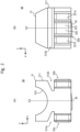
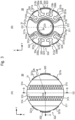
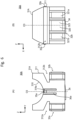
- Fig. 2(A) and Fig. 2(B) are a front view and a side view, respectively, of the rack guide 30 illustrated in Fig. 1 ; and Fig. 3(A) and Fig. 3(B) are a plane view and a bottom view, respectively, of the rack guide 30 illustrated in Fig. 1 . Additionally, Fig. 4(A) and Fig. 4(B) are an A-A cross-sectional view and a B-B cross-sectional view, respectively, of the rack guide 30 illustrated in Fig. 3(A) .
- the rack guide 30 has a rack guide body 31 in a cylindrical shape; a pair of supporting portions 32a, 32b arranged to be movable in a radial direction of the rack guide body 31; biasing portions 33a, 33b designed to bias the supporting portions 32a, 32b outwardly in the radial direction of the rack guide body 31, respectively; and a spring 34.
- the rack guide body 31 has the guide surface 310 defined in a concave manner in a front end face (one end face on the side closer to the rack bar 20) of the rack guide body 31 so as to slide with the back of the rack bar 20; a pair of pockets 312a, 312b each provided in an outer circumferential surface 311 of the rack guide body 31 to hold the corresponding supporting portion 32a, 32b along with the corresponding biasing portion 33a, 33b; and a spring guide 313 designed to contain the spring 34.
- Areas 314 within the guide surface 310, which tend to slide with the back of the rack bar 20, include a large number of depressions each acting as a grease reservoir 315.
- the pockets 312a, 312b are formed on both sides (in a direction (the Y direction) perpendicular to both a direction (the X direction) of sliding between the guide surface 310 and the rack bar 20 and a direction (the Z direction) of an axis O3 of the rack guide 30) of the outer circumferential surface 311 of the rack guide body 31 as if the outer circumferential surface 311 were partially cut off.
- the pocket 312a contains the supporting portion 32a with the biasing portion 33a
- the pocket 312b contains the supporting portion 32b with the biasing portion 33b.
- the spring guide 313 is a cylindrical hole open in a rear end face (another end face on the side closer to the cap 60), and the spring 34 is placed in this spring guide.
- the supporting portions 32a, 32b are arranged on both sides (in the direction (the Y direction) perpendicular to both the direction (the X direction) of sliding between the guide surface 310 and the rack bar and the direction (the Z direction) of the axis O3 of the rack guide 3) of the rack guide body 31 (see Fig. 3(B) ), and are placed in the pockets 312a, 312b along with the biasing portions 33a, 33b, respectively.
- Each of the supporting portions 32a, 32b has a primary protrusion 320 and a pair of secondary protrusions 321a, 321b that are located on both sides (in a circumferential direction of the rack guide body 31) of the primary protrusion 320.
- the primary protrusion 320 has a supporting surface 323 protruding beyond the outer circumferential surface 311 of the rack guide body 31, and this supporting surface 323 is to slide over the inner wall surface 78 of the cylinder casing portion 72 of the housing 70 in the direction (the Z direction) of the axis O3 of the rack guide body 31. This allows the rack guide 30 to be fitted in the cylinder casing portion 72 without any unintended clearance and to slide in the direction of the axis O3 of the rack guide body 31.
- the secondary protrusions 321a, 321b each have a supporting surface 324 that protrudes beyond the outer circumferential surface 311 of the rack guide body 31 but is located more radially inward than the supporting surface 323 of the primary protrusion 320. If any radial load is applied to the primary protrusion 320 sliding over the inner wall surface 78 of the cylinder casing portion 72 of the housing 70 and thereby causes the primary protrusion 320 to move radially inwardly, then the supporting surfaces 324 of the adjacent secondary protrusions 321a, 321b can become in contact with the inner wall surface 78 of the cylinder casing portion 72 of the housing 70 to support the radial load along with the primary protrusion 320.
- the biasing portion 33a is a member in the form of flat spring extending along the circumferential direction of the rack guide body 31 from the both sides (in the circumferential direction) of the supporting portion 32a to connect to the rack guide body 31, and the biasing portion 33b is a member in the form of flat spring extending circumferentially from the both sides (in the circumferential direction of the rack guide body 31) of the supporting portion 32b to connect to the rack guide body 31.
- Each of the biasing portions 33a, 33b includes first flat spring portions 330a, 330b, a second flat spring portion 331a, and a second flat spring portion 331b: for each biasing portion 33a, 33b, the first flat spring portions 330a, 330b extend circumferentially from the corresponding primary protrusion 320 to connect to the corresponding secondary protrusions 321a, 321b, respectively, the second flat spring portion 331a extends circumferentially and radially from the corresponding secondary protrusion 321a toward an edge 317a on the radially outer side of one side wall 316a in the corresponding pocket 312a, 312b to connect to the rack guide body 31, and the second flat spring portion 331b extends circumferentially and radially form the corresponding secondary protrusion 321b toward an edge 317b on the radially outer side of another side wall 316b in the corresponding pocket 312a, 312b to connect to the rack guide body 31.
- the rack guide body 31, the supporting portions 32a, 32b (respective primary protrusions 320 and respective secondary protrusions 321a, 321b), and the biasing portions 33a, 33b (respective first flat spring portions 330a, 330b and respective second flat spring portions 331a, 331b) are all integrally molded into one piece using synthetic resin material, such as polyethylene terephthalate fiber-reinforced with glass, etc., polybutylene terephthalate, polyamide, polyphenylene sulfide, and polyacetal.
- synthetic resin material such as polyethylene terephthalate fiber-reinforced with glass, etc., polybutylene terephthalate, polyamide, polyphenylene sulfide, and polyacetal.
- the spring 34 is, but not limited to, a coil spring or a flat spring, and is placed in the spring guide 313 of the rack guide body 31.
- the spring 34 has a longer free length than the height (depth) of the spring guide 313, and one end portion of the spring 34 projects out of an opening of the spring guide 313 to have a contact with the cap 60. Therefore, the cap 60 can act as a bearing surface for the spring 34, and the spring 34 can bias the rack guide body 31 in a direction to push it toward the rack bar 20 in such a manner that the guide surface 310 contacts with and is pressed against the back 22 of the rack bar 20. This causes the rack gear 21 to be pressed against the pinion gear 11, thereby preventing the opposite teeth in the mesh position between the rack gear 21 and the pinion gear 11 from separating.
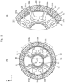
- Fig. 5(A) is a view of the rack guide 30 placed in the cylinder casing portion 72 of the housing 70, as seen from the bottom side of the gear system 1, and Fig. 5(B) is an enlarged view of the part C in Fig. 5(A) .
- the supporting portions 32a, 32b are each under an outward force in the radial direction of the rack guide body 31 from the first flat spring portions 330a, 330b of the respective biasing portions 33a, 33b, and have their respective supporting surfaces 323 projected beyond the outer circumferential surface 311 of the rack guide body 31 and slidable over the inner wall surface 78 of the cylinder casing portion 72 of the housing 70.
- This enables the rack guide 30 in the cylinder casing portion 72 to be placed, without any unintended clearance, movably in the direction of the axis O3.
- the secondary protrusions 321a, 321b are each under an outward force in the radial direction of the rack guide body 31 from the corresponding one of the first flat spring portions 330a, 330b of the corresponding biasing portion 33a, 33b and the corresponding second flat spring portion 331a, 331b, and have their respective supporting surfaces 324 projected beyond the outer circumferential surface 311 of the rack guide body 31 but positioned more radially-inwardly than the supporting surface 323 of the primary protrusion 320; under this situation, if a large radial load acts on the rack guide 30 and thereby causes any one of the primary protrusions 320 to move inwardly in the radial direction, then the supporting surfaces 324 of the corresponding secondary protrusions 321a, 321b each come into contact with the inner wall surface 78 of the cylinder casing portion 72 of the housing 70 to support the radial load along with the primary protrusion 320.
- the supporting portions 32a, 32b are based outwardly in the radial direction of the rack guide body 31 by the respective biasing portions 33a, 33b and thus pressed against the inner wall surface 78 of the cylinder casing portion 72 of the housing 70 while being allowed to slide thereon, thereby supporting the rack guide 30.
- This allows the rack guide 30 to be fitted in the housing 70 without any unintended clearance, resulting in avoidance of rattling noise occurrence.
- the rack guide body 31, the supporting portions 32a, 32b, and the biasing portions 33a, 33b are all made of synthetic resin, and the biasing portions 33a, 33b extend circumferentially from the both sides (in the circumferential direction of the rack guide body 31) of the respective supporting portions 32a, 32b to connect to the rack guide body 31; this structure allows these portions to be integrally molded in a single piece using the same resin material, thereby leading to fewer components and reduced man-hours. Therefore, the present embodiment enables lower-cost manufacturing and successfully provides stability of the supported rack bar 20 while avoiding any rattling noise occurrence.
- each of the supporting portions 32a, 32b has the primary protrusion 320 and a pair of the secondary protrusions 321a, 321b located on both sides (in the circumferential direction of the rack guide body 31) of the primary protrusion 320
- the primary protrusion 320 has the supporting surface 323 protruding beyond the outer circumferential surface 311 of the rack guide body 31
- the secondary protrusions 321a, 321b each have the supporting surface 324 protruding beyond the outer circumferential surface 311 of the rack guide body 31 but located more radially-inwardly than the supporting surface 323 of the primary protrusion 320.
- the supporting surface 323 of the primary protrusion 320 protrudes beyond the outer circumferential surface 311 of the rack guide body 31 to allow it to slide over the inner wall surface 78 of the cylinder casing portion 72 of the housing 70 and thereby supports the rack guide 30; if a large load acts on the rack guide 30 in the radial direction thereby moving the primary protrusion 320 inwardly in the radial direction, then the supporting surfaces 324 of the secondary protrusions 321a, 321b each come into contact with the inner wall surface 78 of the cylinder casing portion 72 of the housing 70 to support the radial load along with the primary protrusion 320. Therefore, according to the present embodiment, even when the large load acts on the rack guide 30 in the radial direction, the rack bar 20 is stably supported while any rattling noise is provided from occurring.
- the biasing portions 33a, 33b each have the first flat spring portions 330a, 330b and the second flat spring portions 331a, 331b, the first flat spring portions 330a, 330b extend circumferentially from the both sides (in the circumferential direction of the rack guide body 31) of the primary protrusion 320 to connect to the secondary protrusions 321a, 321b, and the second flat spring portions 331a, 331b extend circumferentially and radially from the secondary protrusions 321a, 321b toward the edges 317a, 317b on the radially outer sides of the side walls 316a, 316b in the pocket 312a, 312b to connect the rack guide body 31.
- each of the primary protrusions 320 and the corresponding secondary protrusions 321a, 321b allows the primary protrusions 320 to move in the radial direction in response to an application of a large load to the rack guide 30 in the radial direction, thereby causing the biasing portions 33a, 33b to absorb the radial load. Therefore, according to the present embodiment, the potential occurrence of any rattling noise is more effectively avoided even if a larger load is applied to the rack guide 30 in the radial direction.
- the rack guide body 31 has the pockets 312a, 312b defined in the outer circumferential surface 311 of the rack guide body 31 and each containing the supporting portion 32a, 32b along with the corresponding biasing portions 33a, 33b. This prevents the provision of the supporting portions 32a, 32b and the biasing portions 33a, 33b from leading to an increase in size of the rack guide 30.
- the supporting portions 32a, 32b are arranged on both side of the rack guide body 31 in the direction (the Y direction) perpendicular to the direction of sliding between the guide surface 310 and the rack bar 20 (the X direction). Therefore, according to the present embodiment, the supporting portions 32a, 32b can support a possible load acting on the rack bar 20 in the direction (the Y direction) perpendicular to both of the direction of sliding between the guide surface 310 and the rack bar 20 (the X direction) and the direction (the Z direction) of the axis O3 of the rack guide 30 during time when rotary motion of the pinion shaft 10 is transformed into linear motion of the rack bar 20 in a direction (the X direction) of the axis O2, thus more effectively preventing the rack guide 30 from rattling in the cylinder casing portion 72.
- the present invention can include, but is not limited to, the above embodiment: it will be obvious to those skilled in the art that various changes may be made without departing from the scope and sprit of the invention.
- the above embodiment provides, but is not limited to, two supporting portions 32a, 32b along with the respective biasing portions 33a, 33b.
- Three or more supports may be provided along with the respective biasing portions.
- at least one of the supporting portions is preferably arranged on the rack guide body 31 in the direction (the Y direction) perpendicular to the direction of sliding between the guide surface 310_and the rack bar 20 (the X direction).
- each of the supporting portions 32a, 32b has the primary protrusion 320 and a pair of the secondary protrusions 321a, 321b located on both sides of the primary protrusion 320 in the circumferential direction of the rack guide body 31, the primary protrusion 320 has the supporting surface 323 that protrudes beyond the outer circumferential surface 311 of the rack guide body 31, and the secondary protrusions 321a, 321b have the respective supporting surfaces 324 that protrude beyond the outer circumferential surface 311 of the rack guide body 31 but are located more radially inward than the supporting surface 323 of the primary protrusion 320.
- the present invention is however not limited to this aspect.
- the secondary protrusions 321a, 321b each have a lower stiffness than that of the corresponding primary protrusion 320 is, and thus may be of any type as long as, during when a large load is applied to the rack guide 30 in the radial direction, it can reinforce the corresponding primary protrusion 320 and support the load along with the corresponding primary protrusion 320.
- An adjustability for the stiffness of each primary protrusion 320 and for that of each secondary protrusion 321a, 321b is provided, for example, by changing an elastic force of each first flat spring portion 330a, 330b and that of each second flat spring portion 331a, 331b, specifically, by changing at least one of the following dimensions of each first flat spring portion 330a, 330b and at least one of the following dimensions of each second flat spring portion 331a, 331b: length, width, thickness, and size of a round portion.
- each of the supporting portions 32a, 32b includes the primary protrusion 320 and a pair of the secondary protrusions 321a, 321b located on both sides of the primary protrusion 320 in the circumferential direction of the rack guide body 31; however, the present invention is not limited to this aspect.
- One or both of the secondary protrusions 321a, 321b may be omitted.
- another supporting portion slidable with the inner wall surface 78 of the cylinder casing portion 72 of the housing 70 may also be provided on both sides (in the direction (the X direction) of sliding between the guide surface 310 and the rack bar 20) of the outer circumferential surface 311 of the rack guide body 31 so as to be movable in the radial direction of the rack guide body 31.
- Fig. 6(A) and Fig. 6(B) are a front view and a side view, respectively, of a modification 30A of the rack guide 30; and Fig. 7(A) and Fig. 7(B) are a plane view and a bottom view, respectively, of the modification 30A of the rack guide 30. Additionally, Fig. 8(A) and Fig. 8(B) are a D-D cross-sectional view and an E-E cross-sectional view, respectively, of the modification 30A of the rack guide 30 illustrated in Fig. 7 (A) .
- a rack guide 30A as illustrated in Fig. 6 to Fig. 8 differs from the rack guide 30 as illustrated in Fig. 2 to Fig. 4 in that a rack guide body 31A is provided instead of the rack guide body 31 and in that a pair of supporting portions 35a, 35b provided to be movable in a radial direction of the rack guide body 31A and biasing portions 36a, 36b for biasing the supporting portions 35a, 35b outwardly in the radial direction of the rack guide 30A, respectively, are added.
- the other elements are the same as those of the rack guide 30.
- the rack guide body 31A differs from the rack guide body 31 in that a pair of pockets 318a, 318b are added which are provided on an outer circumferential surface 311 of the rack guide body 31A and contain the supporting portions 35a, 35b along with the biasing portions 36a, 36b, respectively.
- the other elements are the same as those of the rack guide body 31.
- the pockets 318a, 318b are defined on both sides (in the direction (the X direction) of sliding between the guide surface 310 and the rack bar 20) of the outer circumferential surface 311 of the rack guide body 31A as if the outer circumferential surface 311 were partially cut off.
- the pocket 318a contains the supporting portion 35a along with biasing portion 36a
- the pocket 318b contains the supporting portion 35b along with the biasing portion 36b.
- the supporting portions 35a, 35b are located on the both side (in the direction (the X direction) of sliding between the guide surface 310 and the rack bar) of the rack guide body 31A, and placed along with the respective biasing portions 36a, 36b in the respective pockets 318a, 318b.
- the biasing portion 36a is a member in the form of a flat spring extending in a direction of an axis O3 of the rack guide body 31A from the supporting portion 35a toward a bottom face 319a in the pocket 318a to connect to the rack guide body 31A
- the biasing portion 36b is a member in the form of a flat spring extending in the direction of the axis O3 of the rack guide body 31A form the supporting portion 35b toward a bottom face 319b in the pocket 318b to connect to the rack guide body 31A.
- the supporting portions 35a, 35b are pressed against and slidable on the inner wall surface 78 of the cylinder casing portion 72 of the housing 70 under an outward force in the radial direction of the rack guide body 31A from the biasing portions 36a, 36b.
- the biasing portions 33a, 33b each are a member in the form of a flat spring extending circumferentially from the both sides (in the circumferential direction of the rack guide body 31) of the corresponding supporting portion 32a, 32b to connect to the rack guide body 31; however the present invention is not limited to this aspect.
- Each of the biasing portions 33a, 33b may have any shape as far as it is a member in the form of a spring having potential to bias the corresponding supporting portion 32a, 32b outwardly in the radial direction of the rack guide body 31.
- the biasing portions 36a, 36b each are a member in the form of a flat springs extending in the direction of the axis O3 of the rack guide body 31A from the corresponding supporting portions 35a, 35b toward the bottom face 319a, 319b in the corresponding pocket 318a, 318b to connect to the rack guide body 31A; however the present invention is not limited to this aspect.
- Each of the biasing portions 36a, 36b may have any shape as for as it is a member in the form of a spring having potential to bias the corresponding supporting portion 35a, 35b outwardly in the radial direction of the rack guide body 31A.
Landscapes
- Engineering & Computer Science (AREA)
- Mechanical Engineering (AREA)
- General Engineering & Computer Science (AREA)
- Chemical & Material Sciences (AREA)
- Combustion & Propulsion (AREA)
- Transportation (AREA)
- Transmission Devices (AREA)
Abstract
Description
- The present invention relates to a rack guide (a support yoke) that supports a rack bar while pressing it against a pinion and guides the rack bar in an axial direction thereof, in a rack and pinion intended for use in a steering device for an automobile and the like, and to a gear system using the same.
- A known rack guide disclosed in
Patent Literature 1, is located behind a back (a surface on the opposite side to the rack gear) of a rack bar put in a housing, in a rack and pinion intended for use in a steering device for an automobile and the like to support the rack bar while pressing it against a pinion and to guide the rack bar in an axial direction thereof. This rack guide is movably installed in the housing and biased in an axial direction of thereof by a spring, and supports the rack bar while sliding with the back of the rack bar. An outer circumferential surface of the rack guide includes narrow slits that are extending the axial direction and arranged at plural equally spaced locations, and a stick-shaped solid lubricant is embedded in each of the slits and exposed from the outer circumferential surface of the rack guide to allow sliding with an inner circumferential surface of the housing. These solid lubricants enable the rack guide to be fitted in the housing without an unintended clearance, thus contributing to avoiding any rattling noise, which would otherwise be caused by rattling of the rack guide within the housing. - [Patent Literature 1]
Japanese Unexamined Patent Application Laid-Open No. 2002-178935 - However, the rack guide disclosed in
Patent Literature 1 has such a structure that one of the stick-shaped solids lubricant is embedded in each of the slits defined in the outer circumferential surface of the rack guide, which leads to an increase in the number of components and the required man-hours, resulting in higher costs. - The present invention has been made in view of the above situation, and an object of the invention is to provide a rack guide having lower manufacturing costs, which can stably support a rack bar and avoid rattling noise occurrence, and a gear system using the same.
- In response to the above issue, the present invention provides a rack guide made of synthetic resin, and the rack guide having the following: a rack guide body having a cylindrical shape with an end face, the end face including a guide surface configured to slide with a back of a rack bars; a plurality of supporting portions each protruding beyond an outer circumferential surface of the rack guide body and being movable in a radial direction of the rack guide body; and a biasing portion provided for each of the supporting portions and made of synthetic resin, the biasing portion extending along a circumferential direction of the rack guide body from both sides (in the circumferential direction) of a corresponding one of the supporting portions and connecting to the rack guide body to have potential to bias the corresponding one of the supporting portions outwardly in the radial direction. Here, the outer circumferential surface of the rack guide body may have a pocket for holding the supporting portions together with the biasing portion.
- For example, a rack guide according to the present invention is that configured to support a rack bar having a rack gear in mesh with a pinion gear from an opposite side to the rack gear while allowing the rack bar to slide, and to guide the rack bar the rack bar moving in response to rotation of the pinion gear in an axial direction of the rack bar; and has the following:
- a rack guide body made of synthetic resin, the rack guide body having a cylindrical shape having an end face, the end face including a guide surface to slide with a back of the rack bar;
- a plurality of supporting portions made of synthetic resin, the supporting portions each protruding beyond an outer circumferential surface of the rack guide body to be movable in a radial direction of the rack guide body; and
- a biasing portion provided for each of the supporting portions and made of synthetic resin, the biasing portion extending along a circumferential direction of the rack guide body from both sides of a corresponding one of the supporting portions in the circumferential direction and connecting to the rack guide body to configured to bias the corresponding one of the supporting portions outwardly in the radial direction of the rack guide body.
- According to the present invention, the biasing portions bias the respective supporting portions outwardly in the radial direction of the rack guide body, thereby causing the supporting portions to support the rack guide while pressing against and sliding with an inner wall of a housing; this causes the rack guide to be fitted in the housing without any unintended clearance, resulting in avoidance of any rattling noise occurrence. Moreover, the rack guide body, the supporting portions, and the biasing portions are all made of synthetic resin, and each biasing portion extends from the both sides (in the circumferential direction of the rack guide body) of the corresponding supporting portion in the circumferential direction and connects to the rack guide body; such a structure can be integrally molded of the same resin material, thus leading to fewer components and man-hours. Therefore, according to the present invention, lower manufacturing costs, stability of the supported rack bar, and avoidance of any rattling noise occurrence are successfully provided.
-
- [
Fig. 1] Fig. 1 is a schematic cross-sectional view of agear system 1 for a steering device according to one embodiment of the present invention. - [
Fig. 2] Fig. 2(A) and Fig. 2(B) are a front view and a side view, respectively, of arack guide 30 illustrated inFig. 1 . - [
Fig. 3] Fig. 3(A) and Fig. 3(B) are a plane view and a bottom view, respectively, of therack guide 30 illustrated inFig. 1 . - [
Fig. 4] Fig. 4(A) and Fig. 4(B) are an A-A cross-sectional view and a B-B cross-sectional view, respectively, of therack guide 30 illustrated inFig. 3(A) . - [
Fig. 5] Fig. 5(A) is a view of therack guide 30 placed in acylinder casing portion 72 of ahousing 70, as seen from the bottom side of thegear system 1, andFig. 5(B) is an enlarged view of the part C inFig. 5(A) . - [
Fig. 6] Fig. 6(A) and Fig. 6(B) are a front view and a side view, respectively, of amodification 30A of therack guide 30. - [
Fig. 7] Fig. 7(A) and Fig. 7(B) are a plane view and a bottom view, respectively, of themodification 30A of therack guide 30. - [
Fig. 8] Fig. 8(A) and Fig. 8(B) are a D-D cross-sectional view and an E-E cross-sectional view, respectively, of themodification 30A of therack guide 30 illustrated inFig. 7 (A) . - In the following, one embodiment of the present invention will be described with reference to the drawings.
- It should be understood that three directions are defined just for convenience of the description below and used in the each drawing where appropriate: a direction of an axis O2 of a rack bar 20 (a direction in which the rack bar 20 it to reciprocate) as an X direction; a direction in which a
rack gear 21 is to pressed against a pinion gear 11 as a Z direction; and a direction perpendicular to the X and Z directions as a Y direction. -
Fig. 1 is a schematic cross-sectional view of agear system 1 for a steering device according to the present embodiment. - The steering device according to the present embodiment has the rack and
pinion gear system 1 which transforms rotary motion of a steering shaft into linear motion and transmits this linear motion to linkages which each change a direction of a corresponding wheel. It should be understood that the steering device may or may not be provided with a power steering system that uses a motor to assist the movement of the pinion gear 11 or of the rack bar 20. - As illustrated in the drawings, this
gear system 1 has the following: apinion shaft 10 having the pinion gear 11 formed thereon; the rack bar 20 having therack gear 21 formed thereon to mesh with the pinion gear 11; a pair of rolling bearings 40 supporting thepinion shaft 10 while allowing thepinion shaft 10 to rotate; arack guide 30 configured to guide the rack bar 20 so as to allow it to reciprocate in the X direction as the pinion gear 11 rotates; ahousing 70 containing thesecomponents 10 to 40; and acap 60 closing thehousing 70. - The
pinion shaft 10, which is a cylindrical members arranged with an axis O1 thereof inclined toward the X direction with respect to the Y direction, has an outer circumferential surface on which the pinion gear 11, such as a helical gear, is defined. The pinion gear 11 is placed in apinion gear compartment 73 defined within thehousing 70, and thepinion shaft 10 is rotatably supported around the axis O1 by thehousing 70 via a pair of the rolling bearings 40 at positions on both sides of the pinion gear 11. Oneend portion 13 of thepinion shaft 10 projects out of thepinion gear compartment 73 through anopening 74 defined in thehousing 70 and is coupled with the steering shaft not illustrated. This allows the pinion gear 11 to rotate in conjunction with the steering shaft rotating in response to an operation of a steering wheel. - The rack bar 20 is a cylindrical member arranged along the X direction, both end of which are, not illustrated, connected via respective ball joints to the respective linkages that each change the direction of the corresponding wheel. Teeth included in the
rack gear 21 are arranged in a row in the X direction in an outer circumferential surface of the rack bar 20, and come into mesh with the teeth of the pinion gear 11 at a predetermined mesh position in thepinion gear compartment 73 of thehousing 70. Depending on a magnitude of a load applied to the rack bar 20, the rack bar 20 can be slidably supported by therack guide 30 on its back (an outer circumferential surface which is located on the opposite side to therack gear 21 and which is arcuate in YZ cross-section) 22. Responsive to rotation of thepinion shaft 10 with the steering shaft, the mesh between the pinion gear 11 and therack gear 21 causes the rack bar 20 to reciprocate in the X direction while being guided by therack guide 30, thereby swinging the linkages. This generates changes of the direction of the wheel in response to the operations of the steering wheel. - The
housing 70 includes arack casing portion 71 in a hollow cylindrical shape, arranged along the X direction; and acylinder casing portion 72 in a hollow cylindrical shape, projecting in the Z direction from the outer periphery of therack casing portion 71. - The
rack casing portion 71 contains the rack bar 20 in such a manner that the rack bar 20 is allowed to reciprocate in the X direction. Thepinion gear compartment 73 is defined in thisrack casing portion 71. As described above, thispinion gear compartment 73 contains the pinion gear 11 and a pair of the rolling bearings 40, and thepinion shaft 10 is rotatably supported by the rolling bearings 40 in such a manner that the pinion gear 11 meshes with therack gear 21 at the predetermined mesh position. Therack casing portion 71 includes anopening 74 connecting the inside and outside of thepinion gear compartment 73 to each other and facing the steering shaft not illustrated, and oneend portion 13 of thepinion shaft 10, which is coupled to the steering shaft not illustrated, projects through thisopening 74 toward the outside of thepinion gear compartment 73. - One the other hand, the
cylinder casing portion 72 is integrally formed with therack casing portion 71 so as to be located on the opposite side of the rack bar 20 from the pinion gear 11, and an inside of thecylinder casing portion 72 and an inside of therack casing portion 71 are connected to each other via an opening 75 facing the pinion gear 11 in thepinion gear compartment 73. Aninner wall surface 78 of thecylinder casing portion 72 includes a threadedportion 77 for securing acap 60, at anopen end 76. - The
rack guide 30, which has aguide surface 310 for supporting theback 22 of the rack bar 20 while allowing it to slide, is arranged in thecylinder casing portion 72 in the Z direction with theguide surface 310 facing theback 22 of the rack bar 20, and is located on the opposite side of the rack bar 20 from the pinion gear 11 (behind theback 22 of the rack bar 20 in the mesh position between the pinion gear 11 and the rack gear 21). A detailed structure of therack guide 30 will be described below. - The
cap 60 has a disc shape attachable to theopen end 76 of thecylinder casing portion 72, and a threadedportion 62 is formed in an outer periphery of thecap 60. Inserting therack guide 30 into thecylinder casing portion 72 of thehousing 70 and then screwing the threadedportion 62 of thecap 60 onto the threadedportion 77 on theopen end 76 of thecylinder casing portion 72 causes thecap 60 to be secured to theopen end 76 of thecylinder casing portion 72 and close thecylinder casing portion 72. - A structure of the
rack guide 30 is described in detail below. -
Fig. 2(A) and Fig. 2(B) are a front view and a side view, respectively, of therack guide 30 illustrated inFig. 1 ; andFig. 3(A) and Fig. 3(B) are a plane view and a bottom view, respectively, of therack guide 30 illustrated inFig. 1 . Additionally,Fig. 4(A) and Fig. 4(B) are an A-A cross-sectional view and a B-B cross-sectional view, respectively, of therack guide 30 illustrated inFig. 3(A) . - As illustrated in the drawings, the
rack guide 30 has arack guide body 31 in a cylindrical shape; a pair of supportingportions rack guide body 31; biasingportions portions rack guide body 31, respectively; and aspring 34. - The
rack guide body 31 has theguide surface 310 defined in a concave manner in a front end face (one end face on the side closer to the rack bar 20) of therack guide body 31 so as to slide with the back of the rack bar 20; a pair ofpockets circumferential surface 311 of therack guide body 31 to hold the corresponding supportingportion corresponding biasing portion spring guide 313 designed to contain thespring 34. -
Areas 314 within theguide surface 310, which tend to slide with the back of the rack bar 20, include a large number of depressions each acting as agrease reservoir 315. - The
pockets guide surface 310 and the rack bar 20 and a direction (the Z direction) of an axis O3 of the rack guide 30) of the outercircumferential surface 311 of therack guide body 31 as if the outercircumferential surface 311 were partially cut off. Thepocket 312a contains the supportingportion 32a with the biasingportion 33a, and thepocket 312b contains the supportingportion 32b with the biasingportion 33b. - The
spring guide 313 is a cylindrical hole open in a rear end face (another end face on the side closer to the cap 60), and thespring 34 is placed in this spring guide. - The supporting
portions guide surface 310 and the rack bar and the direction (the Z direction) of the axis O3 of the rack guide 3) of the rack guide body 31 (seeFig. 3(B) ), and are placed in thepockets portions portions primary protrusion 320 and a pair ofsecondary protrusions primary protrusion 320. - The
primary protrusion 320 has a supportingsurface 323 protruding beyond the outercircumferential surface 311 of therack guide body 31, and this supportingsurface 323 is to slide over theinner wall surface 78 of thecylinder casing portion 72 of thehousing 70 in the direction (the Z direction) of the axis O3 of therack guide body 31. This allows therack guide 30 to be fitted in thecylinder casing portion 72 without any unintended clearance and to slide in the direction of the axis O3 of therack guide body 31. - The
secondary protrusions surface 324 that protrudes beyond the outercircumferential surface 311 of therack guide body 31 but is located more radially inward than the supportingsurface 323 of theprimary protrusion 320. If any radial load is applied to theprimary protrusion 320 sliding over theinner wall surface 78 of thecylinder casing portion 72 of thehousing 70 and thereby causes theprimary protrusion 320 to move radially inwardly, then the supportingsurfaces 324 of the adjacentsecondary protrusions inner wall surface 78 of thecylinder casing portion 72 of thehousing 70 to support the radial load along with theprimary protrusion 320. - The biasing
portion 33a is a member in the form of flat spring extending along the circumferential direction of therack guide body 31 from the both sides (in the circumferential direction) of the supportingportion 32a to connect to therack guide body 31, and the biasingportion 33b is a member in the form of flat spring extending circumferentially from the both sides (in the circumferential direction of the rack guide body 31) of the supportingportion 32b to connect to therack guide body 31. Each of the biasingportions flat spring portions flat spring portion 331a, and a secondflat spring portion 331b: for each biasingportion flat spring portions primary protrusion 320 to connect to the correspondingsecondary protrusions flat spring portion 331a extends circumferentially and radially from the correspondingsecondary protrusion 321a toward anedge 317a on the radially outer side of oneside wall 316a in thecorresponding pocket rack guide body 31, and the secondflat spring portion 331b extends circumferentially and radially form the correspondingsecondary protrusion 321b toward anedge 317b on the radially outer side of anotherside wall 316b in thecorresponding pocket rack guide body 31. - The
rack guide body 31, the supportingportions primary protrusions 320 and respectivesecondary protrusions portions flat spring portions flat spring portions - The
spring 34 is, but not limited to, a coil spring or a flat spring, and is placed in thespring guide 313 of therack guide body 31. Thespring 34 has a longer free length than the height (depth) of thespring guide 313, and one end portion of thespring 34 projects out of an opening of thespring guide 313 to have a contact with thecap 60. Therefore, thecap 60 can act as a bearing surface for thespring 34, and thespring 34 can bias therack guide body 31 in a direction to push it toward the rack bar 20 in such a manner that theguide surface 310 contacts with and is pressed against the back 22 of the rack bar 20. This causes therack gear 21 to be pressed against the pinion gear 11, thereby preventing the opposite teeth in the mesh position between therack gear 21 and the pinion gear 11 from separating. -
Fig. 5(A) is a view of therack guide 30 placed in thecylinder casing portion 72 of thehousing 70, as seen from the bottom side of thegear system 1, andFig. 5(B) is an enlarged view of the part C inFig. 5(A) . - As illustrated in
Fig. 5 (A) and Fig. 5(B) , the supportingportions rack guide body 31 from the firstflat spring portions respective biasing portions surfaces 323 projected beyond the outercircumferential surface 311 of therack guide body 31 and slidable over theinner wall surface 78 of thecylinder casing portion 72 of thehousing 70. This enables therack guide 30 in thecylinder casing portion 72 to be placed, without any unintended clearance, movably in the direction of the axis O3. - Moreover, the
secondary protrusions rack guide body 31 from the corresponding one of the firstflat spring portions corresponding biasing portion flat spring portion surfaces 324 projected beyond the outercircumferential surface 311 of therack guide body 31 but positioned more radially-inwardly than the supportingsurface 323 of theprimary protrusion 320; under this situation, if a large radial load acts on therack guide 30 and thereby causes any one of theprimary protrusions 320 to move inwardly in the radial direction, then the supportingsurfaces 324 of the correspondingsecondary protrusions inner wall surface 78 of thecylinder casing portion 72 of thehousing 70 to support the radial load along with theprimary protrusion 320. - Hereinabove, one embodiment of the present invention has been described.
- According to the present embodiment, the supporting
portions rack guide body 31 by therespective biasing portions inner wall surface 78 of thecylinder casing portion 72 of thehousing 70 while being allowed to slide thereon, thereby supporting therack guide 30. This allows therack guide 30 to be fitted in thehousing 70 without any unintended clearance, resulting in avoidance of rattling noise occurrence. In addition, therack guide body 31, the supportingportions portions portions portions rack guide body 31; this structure allows these portions to be integrally molded in a single piece using the same resin material, thereby leading to fewer components and reduced man-hours. Therefore, the present embodiment enables lower-cost manufacturing and successfully provides stability of the supported rack bar 20 while avoiding any rattling noise occurrence. - In the present embodiment, each of the supporting
portions primary protrusion 320 and a pair of thesecondary protrusions primary protrusion 320, theprimary protrusion 320 has the supportingsurface 323 protruding beyond the outercircumferential surface 311 of therack guide body 31, and thesecondary protrusions surface 324 protruding beyond the outercircumferential surface 311 of therack guide body 31 but located more radially-inwardly than the supportingsurface 323 of theprimary protrusion 320. Consequently, the supportingsurface 323 of theprimary protrusion 320 protrudes beyond the outercircumferential surface 311 of therack guide body 31 to allow it to slide over theinner wall surface 78 of thecylinder casing portion 72 of thehousing 70 and thereby supports therack guide 30; if a large load acts on therack guide 30 in the radial direction thereby moving theprimary protrusion 320 inwardly in the radial direction, then the supportingsurfaces 324 of thesecondary protrusions inner wall surface 78 of thecylinder casing portion 72 of thehousing 70 to support the radial load along with theprimary protrusion 320. Therefore, according to the present embodiment, even when the large load acts on therack guide 30 in the radial direction, the rack bar 20 is stably supported while any rattling noise is provided from occurring. - In the present embodiment, the biasing
portions flat spring portions flat spring portions flat spring portions primary protrusion 320 to connect to thesecondary protrusions flat spring portions secondary protrusions edges side walls pocket rack guide body 31. This allows each of theprimary protrusions 320 and the correspondingsecondary protrusions primary protrusions 320 to move in the radial direction in response to an application of a large load to therack guide 30 in the radial direction, thereby causing the biasingportions rack guide 30 in the radial direction. - In the present embodiment, the
rack guide body 31 has thepockets circumferential surface 311 of therack guide body 31 and each containing the supportingportion corresponding biasing portions portions portions rack guide 30. - In the present embodiment, the supporting
portions rack guide body 31 in the direction (the Y direction) perpendicular to the direction of sliding between theguide surface 310 and the rack bar 20 (the X direction). Therefore, according to the present embodiment, the supportingportions guide surface 310 and the rack bar 20 (the X direction) and the direction (the Z direction) of the axis O3 of therack guide 30 during time when rotary motion of thepinion shaft 10 is transformed into linear motion of the rack bar 20 in a direction (the X direction) of the axis O2, thus more effectively preventing therack guide 30 from rattling in thecylinder casing portion 72. - The present invention can include, but is not limited to, the above embodiment: it will be obvious to those skilled in the art that various changes may be made without departing from the scope and sprit of the invention.
- For example, the above embodiment provides, but is not limited to, two supporting
portions respective biasing portions rack guide body 31 in the direction (the Y direction) perpendicular to the direction of sliding between the guide surface 310_and the rack bar 20 (the X direction). - In the above embodiment, each of the supporting
portions primary protrusion 320 and a pair of thesecondary protrusions primary protrusion 320 in the circumferential direction of therack guide body 31, theprimary protrusion 320 has the supportingsurface 323 that protrudes beyond the outercircumferential surface 311 of therack guide body 31, and thesecondary protrusions surfaces 324 that protrude beyond the outercircumferential surface 311 of therack guide body 31 but are located more radially inward than the supportingsurface 323 of theprimary protrusion 320. However, the present invention is however not limited to this aspect. Thesecondary protrusions primary protrusion 320 is, and thus may be of any type as long as, during when a large load is applied to therack guide 30 in the radial direction, it can reinforce the correspondingprimary protrusion 320 and support the load along with the correspondingprimary protrusion 320. An adjustability for the stiffness of eachprimary protrusion 320 and for that of eachsecondary protrusion flat spring portion flat spring portion flat spring portion flat spring portion - In the above embodiment, each of the supporting
portions primary protrusion 320 and a pair of thesecondary protrusions primary protrusion 320 in the circumferential direction of therack guide body 31; however, the present invention is not limited to this aspect. One or both of thesecondary protrusions - In the above embodiment, in addition to the supporting
portions inner wall surface 78 of thecylinder casing portion 72 of thehousing 70 may also be provided on both sides (in the direction (the X direction) of sliding between theguide surface 310 and the rack bar 20) of the outercircumferential surface 311 of therack guide body 31 so as to be movable in the radial direction of therack guide body 31. -
Fig. 6(A) and Fig. 6(B) are a front view and a side view, respectively, of amodification 30A of therack guide 30; andFig. 7(A) and Fig. 7(B) are a plane view and a bottom view, respectively, of themodification 30A of therack guide 30. Additionally,Fig. 8(A) and Fig. 8(B) are a D-D cross-sectional view and an E-E cross-sectional view, respectively, of themodification 30A of therack guide 30 illustrated inFig. 7 (A) . - A
rack guide 30A as illustrated inFig. 6 to Fig. 8 differs from therack guide 30 as illustrated inFig. 2 to Fig. 4 in that arack guide body 31A is provided instead of therack guide body 31 and in that a pair of supportingportions rack guide body 31A and biasingportions portions rack guide 30A, respectively, are added. The other elements are the same as those of therack guide 30. - The
rack guide body 31A differs from therack guide body 31 in that a pair ofpockets circumferential surface 311 of therack guide body 31A and contain the supportingportions portions rack guide body 31. - The
pockets guide surface 310 and the rack bar 20) of the outercircumferential surface 311 of therack guide body 31A as if the outercircumferential surface 311 were partially cut off. Thepocket 318a contains the supportingportion 35a along with biasingportion 36a, and thepocket 318b contains the supportingportion 35b along with the biasingportion 36b. - The supporting
portions guide surface 310 and the rack bar) of therack guide body 31A, and placed along with therespective biasing portions respective pockets - The biasing
portion 36a is a member in the form of a flat spring extending in a direction of an axis O3 of therack guide body 31A from the supportingportion 35a toward abottom face 319a in thepocket 318a to connect to therack guide body 31A, and the biasingportion 36b is a member in the form of a flat spring extending in the direction of the axis O3 of therack guide body 31A form the supportingportion 35b toward abottom face 319b in thepocket 318b to connect to therack guide body 31A. - According to the
rack guide 30A with the above-mentioned structure, on both sides (in the direction (the X direction) of sliding between theguide surface 310 and the rack bar 20) of therack guide body 31A, the supportingportions inner wall surface 78 of thecylinder casing portion 72 of thehousing 70 under an outward force in the radial direction of therack guide body 31A from the biasingportions housing 70 without any unintended clearance in the direction (the X direction) of sliding between theguide surface 310 and the rack bar 20, thus more effectively preventing any rattling noises from occurring even when a load acts on therack guide 30A in the direction (the X direction) of sliding between theguide surface 310 and the rack bar 20. The other advantages are the same as those of therack guide 30 in illustrated inFig. 2 to Fig. 4 . - In the
rack guide 30 according to the above embodiment, the biasingportions portion rack guide body 31; however the present invention is not limited to this aspect. Each of the biasingportions portion rack guide body 31. Similarly, in themodification 30A of therack guide 30 according to the above embodiment, the biasingportions rack guide body 31A from the corresponding supportingportions bottom face corresponding pocket rack guide body 31A; however the present invention is not limited to this aspect. Each of the biasingportions portion rack guide body 31A. - The above embodiments give the applications to the steering device of vehicle as a non-limited example, but the present invention is available not only for the steering device of vehicle but also widely in general for any device using a rack and pinion gear system, such as focusing system for optical device, for example.
-
- 1: gear system; 10: pinion shaft;
- 11: pinion gear; 12: outer circumferential surface of the
pinion shaft 10; - 13: end portion of the
pinion shaft 10; 20: rack bar; - 21: rack gear; 22: back of the rack bar 20;
- 30: rack guide; 31, 31A: rack guide body;
- 32a, 32b, 35a, 35b: supporting portion;
- 33a, 33b, 36a, 36b: biasing portion;
- 34: spring; 40: rolling bearing;
- 60: cap; 62: threaded portion of the
cap 60 - 70: housing; 71: rack casing portion
- 72: cylinder casing portion; 73: pinion gear compartment
- 74, 75: opening; 76: open end of the
cylinder casing portion 72; - 77: threaded portion of the
cylinder casing portion 72; - 78: inner wall surface of the
cylinder casing portion 72 - 310: guide surface; 311: outer circumferential surface of the
rack guide body 31; - 312a, 312b, 318a, 318b: pocket;
- 313: spring guide;
- 314: slide area in the
guide surface 310; 315: depression; - 316a, 316b: side wall in the
pockets - 319a, 319b: bottom face in the
pocket - 320: primary protrusion; 321a, 321b: secondary protrusion
- 323, 324: supporting surface;
- 317a, 317b: edge on the radially outer side of the
side wall - 330a, 330b: first flat spring portion;
- 331a, 331b: second flat spring portion
Claims (6)
- A rack guide configured to support a rack bar having a rack gear in mesh with a pinion gear from an opposite side to the rack gear while allowing the rack bar to slide, and to guide the rack bar moving in response to rotation of the pinion gear in an axial direction of the rack bar, the rack guide comprising:a rack guide body made of synthetic resin, the rack guide body having a cylindrical shape and an end face including a guide surface configured to slide with a back of the rack bar;a plurality of supporting portions made of synthetic resin, the supporting portions each protruding beyond an outer circumferential surface of the rack guide body to be movable in a radial direction of the rack guide body; anda biasing portion provided for each of the supporting portions and made of synthetic resin, the biasing portion extending along a circumferential direction of the rack guide body from both sides of a corresponding one of the supporting portions in the circumferential direction and connecting to the rack guide body to configured to bias the corresponding one of the supporting portions outwardly in the radial direction of the rack guide body.
- A rack guide according to Claim 1, wherein the supporting portions are located on both sides of the rack guide body, in a direction perpendicular to both an axial direction of the rack guide body and a direction of sliding between the guide surface and the rack bar.
- A rack guide according to Claim 1 or 2,
wherein each of the supporting portions comprises:a primary protrusion having a supporting surface protruding beyond the outer circumferential surface of the rack guide body; anda pair of secondary protrusions, the secondary protrusions being located on both sides of the primary protrusion in the circumferential direction of the rack guide body, each of the secondary protrusions having a supporting surface protruding beyond the outer circumferential surface of the rack guide body. - A rack guide according to Claim 3,
wherein the biasing portion comprises:a pair of first spring portions, each of the first spring portions being arranged along the circumferential direction of the rack guide body and connecting between the primary protrusion and a corresponding one of the secondary protrusions paired; anda pair of second spring portions, each of the second spring portions being arranged along the circumferential direction of the rack guide body and connecting between a corresponding one of the secondary protrusions paired and the rack guide body. - A rack guide according to any one of Claims 1 to 4,
wherein the rack guide body further comprises pockets each being formed in the outer circumferential surface of the rack guide body and containing a corresponding one of the supporting portions and a corresponding one of the biasing portions. - A gear system for changing a moving direction of a moving object in response to rotation of a steering wheel, the gear system comprising:a pinion gear arranged to rotate in response to the rotation of the steering wheel;a rack bar having a rack gear in mesh with the pinion gear, the pinion gear and the rack gear meshing each other to cause the rack bar to reciprocate in response to the rotation of the pinion gear to change a direction of a wheel of the moving object;a rack guide as in any one of Claims 1 to 5, the rack guide supporting the rack bar and allowing the rack bar to move in the axial direction of the rack bar; anda housing containing the rack guide and allowing the rack guide to move in the axial direction of the rack bar.
Applications Claiming Priority (2)
| Application Number | Priority Date | Filing Date | Title |
|---|---|---|---|
| JP2022054327A JP7821662B2 (en) | 2022-03-29 | 2022-03-29 | Rack guide and gear mechanism |
| PCT/JP2023/009178 WO2023189390A1 (en) | 2022-03-29 | 2023-03-09 | Rack guide and gear mechanism |
Publications (2)
| Publication Number | Publication Date |
|---|---|
| EP4502420A1 true EP4502420A1 (en) | 2025-02-05 |
| EP4502420A4 EP4502420A4 (en) | 2026-03-25 |
Family
ID=88200680
Family Applications (1)
| Application Number | Title | Priority Date | Filing Date |
|---|---|---|---|
| EP23779416.9A Pending EP4502420A4 (en) | 2022-03-29 | 2023-03-09 | Rack and pinion guide and gearbox mechanism |
Country Status (5)
| Country | Link |
|---|---|
| US (1) | US12583506B2 (en) |
| EP (1) | EP4502420A4 (en) |
| JP (1) | JP7821662B2 (en) |
| CN (1) | CN118974440A (en) |
| WO (1) | WO2023189390A1 (en) |
Family Cites Families (11)
| Publication number | Priority date | Publication date | Assignee | Title |
|---|---|---|---|---|
| JPS59216764A (en) * | 1983-05-24 | 1984-12-06 | Toyota Motor Corp | Rack and pinion type steering device |
| JPH09104350A (en) * | 1995-10-09 | 1997-04-22 | Nok Corp | Bearing supporting structure for rack of rack-and-pinion type steering device |
| JP4029567B2 (en) | 2000-12-15 | 2008-01-09 | 株式会社ジェイテクト | Steering device |
| JP5025212B2 (en) | 2006-09-28 | 2012-09-12 | オイレス工業株式会社 | Rack guide and rack and pinion type steering apparatus provided with the rack guide |
| JP2009113732A (en) | 2007-11-09 | 2009-05-28 | Hitachi Ltd | Rack shaft support device and rack and pinion type steering device using the same |
| FR2951797B1 (en) | 2009-10-23 | 2011-10-28 | Jtekt Europe Sas | PUSH-BUTTON DEVICE WITH GAME COMPENSATION FOR DIRECTION WITH RACK OF MOTOR VEHICLE |
| JP2018144701A (en) * | 2017-03-07 | 2018-09-20 | 株式会社ジェイテクト | Rack guide device |
| JP6934801B2 (en) * | 2017-10-20 | 2021-09-15 | マツダ株式会社 | Rack bush and steering mechanism |
| US11198466B2 (en) | 2017-11-03 | 2021-12-14 | Steering Solutions Ip Holding Corporation | Wedge adjuster plug |
| US10963075B2 (en) | 2018-09-14 | 2021-03-30 | Sharp Kabushiki Kaisha | Input detecting device |
| JP2021079886A (en) | 2019-11-21 | 2021-05-27 | オイレス工業株式会社 | Rack guide and gear mechanism |
-
2022
- 2022-03-29 JP JP2022054327A patent/JP7821662B2/en active Active
-
2023
- 2023-03-09 US US18/844,315 patent/US12583506B2/en active Active
- 2023-03-09 EP EP23779416.9A patent/EP4502420A4/en active Pending
- 2023-03-09 WO PCT/JP2023/009178 patent/WO2023189390A1/en not_active Ceased
- 2023-03-09 CN CN202380028454.7A patent/CN118974440A/en active Pending
Also Published As
| Publication number | Publication date |
|---|---|
| US20250196910A1 (en) | 2025-06-19 |
| CN118974440A (en) | 2024-11-15 |
| JP7821662B2 (en) | 2026-02-27 |
| JP2023146897A (en) | 2023-10-12 |
| EP4502420A4 (en) | 2026-03-25 |
| US12583506B2 (en) | 2026-03-24 |
| WO2023189390A1 (en) | 2023-10-05 |
Similar Documents
| Publication | Publication Date | Title |
|---|---|---|
| KR0158068B1 (en) | Bearings for steering column | |
| JP6462523B2 (en) | Actuator and vehicle door opening / closing actuator | |
| JP6478863B2 (en) | Actuator and vehicle door opening / closing actuator | |
| US7594819B2 (en) | Rotary connector | |
| BRPI0811827B1 (en) | AUTOMOTIVE VEHICLE SUSPENSION STOP | |
| EP1975430A1 (en) | Bush bearing device, and rack and pinion steering device for automobile, using the same | |
| US5192137A (en) | Flexible plain bearing and its application to motor vehicle steering mechanisms | |
| KR20020062270A (en) | Electric storage type door mirror | |
| US20100031768A1 (en) | Energy absorbing steering column | |
| JP6909789B2 (en) | Plain bearing | |
| CN105209318A (en) | Synthetic resin plain bearings | |
| US20050274585A1 (en) | Freewheeling clutch | |
| US12583506B2 (en) | Rack guide and gear mechanism | |
| JP7156379B2 (en) | Rack and pinion type steering gear unit | |
| US7694600B2 (en) | Ball screw | |
| JPH07190052A (en) | Elastic bearing made of synthetic resin | |
| US4716327A (en) | Electric motor bearing | |
| GB2100337A (en) | A ball-and-socket joint | |
| WO2017010207A1 (en) | Fixation structure for deflector of flop-over-type ball screw | |
| US20090168444A1 (en) | Motor and guiding structure thereof | |
| US20210309283A1 (en) | Rack and pinion steering gear unit | |
| US20080060469A1 (en) | Vehicle steering wheel | |
| CN111164329B (en) | Thrust plain bearing | |
| JP2732852B2 (en) | Self-adjusting pivot joint used in automobiles | |
| JP6816491B2 (en) | Vehicle window glass lifting device, moving body drive device, and sunroof device |
Legal Events
| Date | Code | Title | Description |
|---|---|---|---|
| STAA | Information on the status of an ep patent application or granted ep patent |
Free format text: STATUS: THE INTERNATIONAL PUBLICATION HAS BEEN MADE |
|
| PUAI | Public reference made under article 153(3) epc to a published international application that has entered the european phase |
Free format text: ORIGINAL CODE: 0009012 |
|
| STAA | Information on the status of an ep patent application or granted ep patent |
Free format text: STATUS: REQUEST FOR EXAMINATION WAS MADE |
|
| 17P | Request for examination filed |
Effective date: 20240814 |
|
| AK | Designated contracting states |
Kind code of ref document: A1 Designated state(s): AL AT BE BG CH CY CZ DE DK EE ES FI FR GB GR HR HU IE IS IT LI LT LU LV MC ME MK MT NL NO PL PT RO RS SE SI SK SM TR |
|
| DAV | Request for validation of the european patent (deleted) | ||
| DAX | Request for extension of the european patent (deleted) | ||
| REG | Reference to a national code |
Ref country code: DE Ref legal event code: R079 Free format text: PREVIOUS MAIN CLASS: F16H0019040000 Ipc: B62D0003120000 |
|
| A4 | Supplementary search report drawn up and despatched |
Effective date: 20260219 |
|
| RIC1 | Information provided on ipc code assigned before grant |
Ipc: B62D 3/12 20060101AFI20260213BHEP Ipc: F16H 19/04 20060101ALI20260213BHEP Ipc: F16H 55/28 20060101ALI20260213BHEP |