EP4502407A1 - Bearing device - Google Patents
Bearing device Download PDFInfo
- Publication number
- EP4502407A1 EP4502407A1 EP23779304.7A EP23779304A EP4502407A1 EP 4502407 A1 EP4502407 A1 EP 4502407A1 EP 23779304 A EP23779304 A EP 23779304A EP 4502407 A1 EP4502407 A1 EP 4502407A1
- Authority
- EP
- European Patent Office
- Prior art keywords
- bearing
- retaining member
- bearing device
- gas sensor
- ring
- Prior art date
- Legal status (The legal status is an assumption and is not a legal conclusion. Google has not performed a legal analysis and makes no representation as to the accuracy of the status listed.)
- Pending
Links
Images


Classifications
-
- F—MECHANICAL ENGINEERING; LIGHTING; HEATING; WEAPONS; BLASTING
- F16—ENGINEERING ELEMENTS AND UNITS; GENERAL MEASURES FOR PRODUCING AND MAINTAINING EFFECTIVE FUNCTIONING OF MACHINES OR INSTALLATIONS; THERMAL INSULATION IN GENERAL
- F16C—SHAFTS; FLEXIBLE SHAFTS; ELEMENTS OR CRANKSHAFT MECHANISMS; ROTARY BODIES OTHER THAN GEARING ELEMENTS; BEARINGS
- F16C41/00—Other accessories, e.g. devices integrated in the bearing not relating to the bearing function as such
- F16C41/004—Electro-dynamic machines, e.g. motors, generators, actuators
-
- H—ELECTRICITY
- H04—ELECTRIC COMMUNICATION TECHNIQUE
- H04Q—SELECTING
- H04Q9/00—Arrangements in telecontrol or telemetry systems for selectively calling a substation from a main station, in which substation desired apparatus is selected for applying a control signal thereto or for obtaining measured values therefrom
-
- F—MECHANICAL ENGINEERING; LIGHTING; HEATING; WEAPONS; BLASTING
- F16—ENGINEERING ELEMENTS AND UNITS; GENERAL MEASURES FOR PRODUCING AND MAINTAINING EFFECTIVE FUNCTIONING OF MACHINES OR INSTALLATIONS; THERMAL INSULATION IN GENERAL
- F16C—SHAFTS; FLEXIBLE SHAFTS; ELEMENTS OR CRANKSHAFT MECHANISMS; ROTARY BODIES OTHER THAN GEARING ELEMENTS; BEARINGS
- F16C19/00—Bearings with rolling contact, for exclusively rotary movement
- F16C19/02—Bearings with rolling contact, for exclusively rotary movement with bearing balls essentially of the same size in one or more circular rows
- F16C19/04—Bearings with rolling contact, for exclusively rotary movement with bearing balls essentially of the same size in one or more circular rows for radial load mainly
-
- F—MECHANICAL ENGINEERING; LIGHTING; HEATING; WEAPONS; BLASTING
- F16—ENGINEERING ELEMENTS AND UNITS; GENERAL MEASURES FOR PRODUCING AND MAINTAINING EFFECTIVE FUNCTIONING OF MACHINES OR INSTALLATIONS; THERMAL INSULATION IN GENERAL
- F16C—SHAFTS; FLEXIBLE SHAFTS; ELEMENTS OR CRANKSHAFT MECHANISMS; ROTARY BODIES OTHER THAN GEARING ELEMENTS; BEARINGS
- F16C19/00—Bearings with rolling contact, for exclusively rotary movement
- F16C19/02—Bearings with rolling contact, for exclusively rotary movement with bearing balls essentially of the same size in one or more circular rows
- F16C19/04—Bearings with rolling contact, for exclusively rotary movement with bearing balls essentially of the same size in one or more circular rows for radial load mainly
- F16C19/06—Bearings with rolling contact, for exclusively rotary movement with bearing balls essentially of the same size in one or more circular rows for radial load mainly with a single row or balls
-
- F—MECHANICAL ENGINEERING; LIGHTING; HEATING; WEAPONS; BLASTING
- F16—ENGINEERING ELEMENTS AND UNITS; GENERAL MEASURES FOR PRODUCING AND MAINTAINING EFFECTIVE FUNCTIONING OF MACHINES OR INSTALLATIONS; THERMAL INSULATION IN GENERAL
- F16C—SHAFTS; FLEXIBLE SHAFTS; ELEMENTS OR CRANKSHAFT MECHANISMS; ROTARY BODIES OTHER THAN GEARING ELEMENTS; BEARINGS
- F16C33/00—Parts of bearings; Special methods for making bearings or parts thereof
- F16C33/30—Parts of ball or roller bearings
- F16C33/66—Special parts or details in view of lubrication
- F16C33/6603—Special parts or details in view of lubrication with grease as lubricant
- F16C33/6622—Details of supply and/or removal of the grease, e.g. purging grease
- F16C33/6625—Controlling or conditioning the grease supply
-
- F—MECHANICAL ENGINEERING; LIGHTING; HEATING; WEAPONS; BLASTING
- F16—ENGINEERING ELEMENTS AND UNITS; GENERAL MEASURES FOR PRODUCING AND MAINTAINING EFFECTIVE FUNCTIONING OF MACHINES OR INSTALLATIONS; THERMAL INSULATION IN GENERAL
- F16C—SHAFTS; FLEXIBLE SHAFTS; ELEMENTS OR CRANKSHAFT MECHANISMS; ROTARY BODIES OTHER THAN GEARING ELEMENTS; BEARINGS
- F16C41/00—Other accessories, e.g. devices integrated in the bearing not relating to the bearing function as such
- F16C41/005—Fluid passages not relating to lubrication or cooling
-
- F—MECHANICAL ENGINEERING; LIGHTING; HEATING; WEAPONS; BLASTING
- F16—ENGINEERING ELEMENTS AND UNITS; GENERAL MEASURES FOR PRODUCING AND MAINTAINING EFFECTIVE FUNCTIONING OF MACHINES OR INSTALLATIONS; THERMAL INSULATION IN GENERAL
- F16C—SHAFTS; FLEXIBLE SHAFTS; ELEMENTS OR CRANKSHAFT MECHANISMS; ROTARY BODIES OTHER THAN GEARING ELEMENTS; BEARINGS
- F16C41/00—Other accessories, e.g. devices integrated in the bearing not relating to the bearing function as such
- F16C41/007—Encoders, e.g. parts with a plurality of alternating magnetic poles
-
- F—MECHANICAL ENGINEERING; LIGHTING; HEATING; WEAPONS; BLASTING
- F16—ENGINEERING ELEMENTS AND UNITS; GENERAL MEASURES FOR PRODUCING AND MAINTAINING EFFECTIVE FUNCTIONING OF MACHINES OR INSTALLATIONS; THERMAL INSULATION IN GENERAL
- F16C—SHAFTS; FLEXIBLE SHAFTS; ELEMENTS OR CRANKSHAFT MECHANISMS; ROTARY BODIES OTHER THAN GEARING ELEMENTS; BEARINGS
- F16C41/00—Other accessories, e.g. devices integrated in the bearing not relating to the bearing function as such
- F16C41/008—Identification means, e.g. markings, RFID-tags; Data transfer means
-
- F—MECHANICAL ENGINEERING; LIGHTING; HEATING; WEAPONS; BLASTING
- F16—ENGINEERING ELEMENTS AND UNITS; GENERAL MEASURES FOR PRODUCING AND MAINTAINING EFFECTIVE FUNCTIONING OF MACHINES OR INSTALLATIONS; THERMAL INSULATION IN GENERAL
- F16N—LUBRICATING
- F16N29/00—Special means in lubricating arrangements or systems providing for the indication or detection of undesired conditions; Use of devices responsive to conditions in lubricating arrangements or systems
- F16N29/04—Special means in lubricating arrangements or systems providing for the indication or detection of undesired conditions; Use of devices responsive to conditions in lubricating arrangements or systems enabling a warning to be given; enabling moving parts to be stopped
-
- F—MECHANICAL ENGINEERING; LIGHTING; HEATING; WEAPONS; BLASTING
- F16—ENGINEERING ELEMENTS AND UNITS; GENERAL MEASURES FOR PRODUCING AND MAINTAINING EFFECTIVE FUNCTIONING OF MACHINES OR INSTALLATIONS; THERMAL INSULATION IN GENERAL
- F16C—SHAFTS; FLEXIBLE SHAFTS; ELEMENTS OR CRANKSHAFT MECHANISMS; ROTARY BODIES OTHER THAN GEARING ELEMENTS; BEARINGS
- F16C2233/00—Monitoring condition, e.g. temperature, load, vibration
-
- F—MECHANICAL ENGINEERING; LIGHTING; HEATING; WEAPONS; BLASTING
- F16—ENGINEERING ELEMENTS AND UNITS; GENERAL MEASURES FOR PRODUCING AND MAINTAINING EFFECTIVE FUNCTIONING OF MACHINES OR INSTALLATIONS; THERMAL INSULATION IN GENERAL
- F16N—LUBRICATING
- F16N2200/00—Condition of lubricant
- F16N2200/02—Oxidation
-
- F—MECHANICAL ENGINEERING; LIGHTING; HEATING; WEAPONS; BLASTING
- F16—ENGINEERING ELEMENTS AND UNITS; GENERAL MEASURES FOR PRODUCING AND MAINTAINING EFFECTIVE FUNCTIONING OF MACHINES OR INSTALLATIONS; THERMAL INSULATION IN GENERAL
- F16N—LUBRICATING
- F16N2210/00—Applications
- F16N2210/14—Bearings
-
- F—MECHANICAL ENGINEERING; LIGHTING; HEATING; WEAPONS; BLASTING
- F16—ENGINEERING ELEMENTS AND UNITS; GENERAL MEASURES FOR PRODUCING AND MAINTAINING EFFECTIVE FUNCTIONING OF MACHINES OR INSTALLATIONS; THERMAL INSULATION IN GENERAL
- F16N—LUBRICATING
- F16N2230/00—Signal processing
-
- F—MECHANICAL ENGINEERING; LIGHTING; HEATING; WEAPONS; BLASTING
- F16—ENGINEERING ELEMENTS AND UNITS; GENERAL MEASURES FOR PRODUCING AND MAINTAINING EFFECTIVE FUNCTIONING OF MACHINES OR INSTALLATIONS; THERMAL INSULATION IN GENERAL
- F16N—LUBRICATING
- F16N2260/00—Fail safe
- F16N2260/02—Indicating
- F16N2260/06—Temperature
-
- G—PHYSICS
- G01—MEASURING; TESTING
- G01N—INVESTIGATING OR ANALYSING MATERIALS BY DETERMINING THEIR CHEMICAL OR PHYSICAL PROPERTIES
- G01N33/00—Investigating or analysing materials by specific methods not covered by groups G01N1/00 - G01N31/00
- G01N33/26—Oils; Viscous liquids; Paints; Inks
- G01N33/28—Oils, i.e. hydrocarbon liquids
- G01N33/2888—Lubricating oil characteristics, e.g. deterioration
Definitions
- the present disclosure relates to a bearing device.
- a bearing device including a sensor provided at a position adjacent to a bearing is used for monitoring the state of a rolling bearing for safety of the device.
- This bearing device may be configured to wirelessly transmit data detected by the sensor in order to transmit such data with greater convenience.
- Japanese Patent Laying-Open No. 2017-72170 discloses an example of the bearing device described above.
- a multipole ring magnet is provided on one axial end face of a retainer of a bearing, an annular seal is placed to close a gap between an inner ring and an outer ring, and a power generation coil and a wireless processing circuit are placed on the surface of the annular seal on the side facing the multipole ring magnet.
- WO 2017/188314 discloses an example in which the sensor of the bearing device described above is a gas sensor that detects deterioration of a lubricant used for the bearing.
- At least one gas sensor and a wireless communication circuit are mounted on the circuit board, the at least one gas sensor detecting a state of the bearing, the wireless communication circuit wirelessly transmitting an output of the at least one gas sensor to outside.
- the side plate portion has a through hole connecting a first surface facing the rolling element to a second surface located opposite to the first surface. A porous membrane is attached so as to cover the through hole.
- the region of sensor unit 6 of bearing device 1 may be divided into two in the radial direction of retaining member 12 by a partition wall (not shown). Also in this case, circuit board 13 is arranged in the radially outer region, and stator 5 of craw-pole-type generator G is arranged in the radially inner region, similarly to the above. Magnetic ring 7 is arranged on the inner diameter side facing stator 5.
- Bearing device 1 of the present embodiment has the following features in addition to the structure of Embodiment 1.
- Power supply PWR (see Fig. 1 ) is an electromagnetic generator (generator G) including magnetic ring 7 fixed to the other ring different from the any one ring of outer ring 3 and inner ring 4, and coil 24 attached to retaining member 12 so as to face magnetic ring 7 in the radial direction of bearing 2.
- a plurality of permanent magnets or a magnetic body having a plurality of magnetic poles may be fixed to magnetic ring 7 as multipolar magnet 7b.
- stator 5 and magnetic ring 7 radially arranged constitute craw-pole-type generator G.
- stator 5 and magnetic ring 7 can achieve a stable amount of power generation by generator G.
- the thus generated electric power can be used in wireless communication circuit 18, enabling stable wireless transmission of radio waves to outside of bearing 2.
- Fig. 9 is a perspective view of a sensor unit in Embodiment 4.
- a feeding device 34 including a power reception circuit 32 and a power transmission circuit 33, which transmits a signal to power reception circuit 32 in a contactless manner, is used as power supply PWR included in bearing device 1 of Embodiment 1.
- Power reception circuit 32 is fixed to front surface 12f of side plate portion 12A of retaining member 12.
- (the substrate of) power reception circuit 32 preferably has, for example, an arc planar shape so as to conform to the shape of front surface 12f.
- Feeding device 34 corresponds to storage battery 31 in Embodiment 3 and functions similarly to storage battery 31.
- Fig. 10 is a sectional view of a bearing device of Embodiment 5. This corresponds to a sectional view in a plane including axis of rotation O in Fig. 11 of Embodiment 6, which will be described later.
- the position of each member fixed to retaining member 12 is not necessarily consistent with its actual position.
- bearing device 1 of the present embodiment basically has a similar structure to that of bearing device 1 of Fig. 1 described above, and accordingly, the description of matters overlapping those of Embodiment 1 will be omitted as appropriate.
- Side plate portion 12A is arranged, at a position axially closest to rolling element 8 in retaining member 12 (on the inner side in bearing 2), adjacent to rolling element 8.
- Side plate portion 12A has back surface 12b (first surface) on the side facing rolling element 8 and front surface 12f (second surface) on the side opposite to back surface 12b (i.e., the side not facing rolling element 8).
- back surface 12b faces the inside of bearing 2
- front surface 12f faces the outside of bearing 2.
- Side plate portion 12A has a through hole 42 connecting back surface 12b to front surface 12f.
- Through hole 42 is contiguous to the space adjacent to rolling element 8 inside bearing 2.
- a porous membrane 41 is attached so as to cover through hole 42.
- porous membrane 41 covers through hole 42 axially from the rolling element 8 side (back surface 12b side), thereby closing through hole 42.
- porous membrane 41 closes through hole 42 in the axial direction.
- Porous membrane 41 mainly contains a fluororesin.
- porous membrane 41 is mostly made of the fluororesin though it may contain a trace amount of material other than the fluororesin.
- the size (the diameter of a largest part) of a hole included in porous membrane 41 is, for example, preferably 10 nm or more and 100 ⁇ m or less, and more preferably, 100 nm or more and 10 ⁇ m or less.
- porous membrane 41 is arranged in through hole 42 so as to close a cross section intersecting the direction (axial direction) of extension of through hole 42.
- Gas sensor SSR may be, for example, a sensor employing a micro-electro mechanical systems (MEMS) technique.
- MEMS micro-electro mechanical systems
- This gas sensor SSR has a structure in which a sensitive film that reacts to a specific gas is supported by a plurality of detection units.
- the sensitive film deforms as gas is adsorbed to the sensitive film.
- Gas sensor SSR detects a gas based on a distortion (a change in electric resistance) of the detection unit induced by the deformation.
- Gas sensor SSR is preferably a gas sensor that detects at least any of an aldehyde and a carboxylic acid with a carbon number of 8 or less.
- Bearing device 1 includes bearing 2 and retaining member 12.
- Bearing 2 includes outer ring 3, inner ring 4, and rolling element 8.
- Retaining member 12 is fixed to any one ring of outer ring 3 and inner ring 4.
- Retaining member 12 includes side plate portion 12A having a width in the radial direction and extending in the circumferential direction.
- At least part of power supply PWR that can generate electric power and circuit board 13 are fixed to retaining member 12.
- Circuit board 13 is fixed to, in the axial direction, the surface (front surface 12f) of side plate portion 12A not facing rolling element 8.
- At least one gas sensor SSR that detects a state of bearing 2 and wireless communication circuit 18 that wirelessly transmits an output of gas sensor SSR to outside are mounted on circuit board 13.
- Side plate portion 12A has through hole 42 that connects the first surface (back surface 12b) facing rolling element 8 to the second surface (front surface 12f) located opposite to the first surface and is contiguous to a space adjacent to rolling element 8.
- Porous membrane 41 is attached so as to cover through hole 42.
- through hole 42 may be formed to connect an internal space formed between outer ring 3 and inner ring 4 of bearing 2 to a space in which gas sensor SSR is arranged.
- the internal space formed between outer ring 3 and inner ring 4 is a space in which rolling element 8 is arranged.
- circuit board 13 Since circuit board 13 is fixed to front surface 12f, circuit board 13 is fixed onto retaining member 12 so as to face the outside of bearing 2. For this reason, even when a metallic retaining member having rigidity higher than that of a resin is used as retaining member 12, the following problem can be suppressed, for example, a problem of failing to transmit radio waves from wireless communication circuit 18 or the like mounted on circuit board 13 to outside of bearing 2 because the radio waves are blocked. In other words, wireless transmission of radio waves to outside of bearing 2 can be performed stably.
- Wireless transmission of radio waves to outside of bearing 2 can be performed stably by wireless communication circuit 18 that receives an output signal of gas sensor SSR and wirelessly transmits the output signal to outside.
- porous membrane 41 allows the above-mentioned gas of the product to pass therethrough but prevents intrusion of abrasion powder, dust, and oil content into bearing 2.
- porous membrane 41 is attached to through hole 42 of side plate portion 12A, only the gas of the product can pass through from the inside of bearing 2 to the front surface 12f side of side plate portion 12A.
- gas sensor SSR mounted on circuit board 13 on the front surface 12f side.
- gas sensor SSR can detect only the gas generated by the lubricant with high accuracy.
- the present embodiment can suppress the following problem, for example, a problem of short-circuit or deterioration of wireless communication circuit 18 due to intrusion of a metallic foreign body and a lubricant into (e.g., wireless communication circuit 18 mounted on) circuit board 13 on the front surface 12f side.
- bearing device 1 can be provided that can prevent a decrease in detection sensitivity of gas sensor SSR and can stably perform wireless transmission of radio waves to outside of bearing 2, irrespective of the quality of material of retaining member 12.
- circuit board 13 is covered with non-metallic lid 14. This can suppress accidental escape of the gas generated inside bearing 2 from gas sensor SSR after flowing to gas sensor SSR mounted on circuit board 13. This is because lid 14 blocks a flow of the gas. As a result, the gas generated inside bearing 2 can be supplied to gas sensor SSR more reliably. This further increases the gas detection sensitivity in gas sensor SSR.
- porous membrane 41 is preferably arranged in through hole 42 so as to close the cross section intersecting the direction of extension of through hole 42. Consequently, the gas passing through porous membrane 41 easily flows through through hole 42 toward gas sensor SSR.
- porous membrane 41 in through hole 42 may be any position.
- porous membrane 41 may be arranged on the front surface 12f side (right) or arranged at the central portion in through hole 42 in Fig. 10 .
- Porous membrane 41 is more preferably arranged on the back surface 12b side (left) in through hole 42.
- porous membrane 41 is arranged at a position closer to outer ring 3, inner ring 4, and rolling element 8 inside bearing 2. Consequently, the gas generated by the lubricant or the like inside bearing 2 reaches porous membrane 41 more easily. This facilitates inflow of the gas from porous membrane 41 into through hole 42 and toward gas sensor SSR.
- porous membrane 41 mainly contains a fluororesin.
- porous membrane 41 allows only the gas generated by oxidation of the lubricant of bearing 2 to flow therethrough and allows inflow of the gas toward gas sensor SSR mounted on circuit board 13.
- porous membrane 41 prevents intrusion of abrasion powder, dust, and oil content inside bearing 2 to gas sensor SSR and wireless communication circuit 18 on circuit board 13.
- gas sensor SSR detects at least any of an aldehyde and a carboxylic acid with a carbon number of 8 or less. Specifically, what is detected by gas sensor SSR is preferably a gas of each compound shown in Table 1 (chain aliphatic aldehydes) and Table 2 (carboxylic acids) below.
- Tables 1 and 2 show chain aliphatic aldehydes and carboxylic acids having a low molecular weight. In these compounds, a compound with a smaller carbon number has a lower boiling point (i.e., volatiles more easily). Thus, the gas of the compound with a small carbon number is suitable for a target to be detected by a gas sensor.
- the temperature conditions on which bearing 2 is used are varied.
- a typical material for the rolling bearing is SUJ2, which is carbon steel for bearings.
- the allowable upper-limit temperature of a bearing produced by a standard heat treatment of SUJ2 is approximately 120°C. However, the bearing can be used at 200°C or higher temperature by being subjected to dimensional stabilization. Considering such operating conditions for typical bearings, an aldehyde and a carboxylic acid with a carbon number of 8 or less are particularly suitable as a target product for detecting oxidation of a lubricant.
- bearing 2 includes retainer 9 retaining rolling elements 8 at intervals in the circumferential direction.
- Retainer 9 has a shape to be opened on the first end face side and coupled on the second end face side in the axial direction.
- Retaining member 12 is arranged at a position on the first end face side of retainer 9 relative to rolling element 8.
- bearing device 1 since one axial end face of retainer 9 is opened, a space in which circuit board 13, power supply PWR, and the like are arranged is provided in the opened portion (the portion in which retainer 9 is originally arranged). In other words, the space for arranging circuit board 13 and power supply PWR is effectively provided inside bearing 2. Also, gas sensor SSR that detects the state of, for example, deterioration of the lubricant of bearing 2 can be arranged in the space described above. Thus, gas sensor SSR can be arranged at a position very close to bearing 2, enabling highly accurate detection of an abnormality of bearing 2 by gas sensor SSR.
- retaining member 12 may be made of metal.
- retaining member 12 Since retaining member 12 is made of metal, retaining member 12 can retain circuit board 13 and gas sensor SSR placed on circuit board 13 so as to have high rigidity. Accordingly, if retaining member 12 is directly fixed to vibrating bearing 2, a malfunction of gas sensor SSR can be suppressed. This allows bearing device 1 to stably perform monitoring of deterioration of the lubricant by gas sensor SSR and wireless transmission of data detected by gas sensor SSR, even in a use environment in which vibrations are applied.
- Fig. 11 is a perspective view of the entire bearing device of Embodiment 6. Referring to Fig. 11 , bearing device 1 includes bearing 2, sensor unit 6, and magnetic ring 7. Since Fig. 11 shows components similar to those of Fig. 2 , description of the matters overlapping those of Fig. 2 will be omitted as appropriate.
- Lid 14 of the present embodiment may be arranged so as to cover the region other than stator 5 as in Fig. 12 .
- lid 14 may be arranged so as to cover stator 5 as well.
- lid 14 covers circuit board 13.
- the distance between gas sensor SSR and through hole 42 is preferably smaller.
- Fig. 12 which will be described next, shows gas sensor SSR at the position of wireless communication circuit 18 in the other figures.
- the position of each member in retaining member 12 does not necessarily indicate its actual position in Fig. 12 and the following sectional views, similarly to Fig. 10 .
- Fig. 12 is a sectional view of a bearing in a plane including an axis of rotation.
- stepped first cut-away portion 3a is formed in the inner circumferential surface of outer ring 3 at one end, as in Embodiment 5.
- stepped second cut-away portion 4a is formed in the outer circumferential surface of inner ring 4 at one end so as to face first cut-away portion 3a.
- annular recess 50 which is cut out toward rolling element 8 by first cut-away portion 3a and second cut-away portion 4a, is formed over outer ring 3 and inner ring 4. Since Fig. 12 basically shows components similar to those of Fig. 3 except that porous membrane 41 and through hole 42 are provided, description of the overlapping matters will not be repeated.
- Fig. 13 is a view for describing a retainer.
- Fig. 13 shows similar components to those of Fig. 4 , and accordingly, description thereof will not be repeated.
- Fig. 14 is a view of a bearing device viewed from the sensor unit side. In Fig. 14 , part of lid 14 is omitted such that the inside of sensor unit 6 is visible. Referring to Fig. 14 , one or more gas sensors SSR that monitor the state of bearing 2 are mounted on circuit board 13. In addition, for example, acceleration sensor 15 and temperature sensor 16 may be mounted on circuit board 13. Since Fig. 14 basically shows similar components to those of Fig. 5 except that porous membrane 41 and through hole 42 are provided, description of the overlapping matters will not be repeated.
- Fig. 15 is an exploded perspective view of a sensor unit in Embodiment 6.
- Fig. 16 is a perspective view of the sensor unit after being assembled in Embodiment 6. Since Figs. 15 and 16 basically show similar components to those of Figs. 6 and 7 except that porous membrane 41 and through hole 42 are provided, description thereof will not be repeated.
- the method of assembling stator 5 is similar to that of Embodiment 2 described above, and accordingly, description thereof will not be repeated.
- the present embodiment includes porous membrane 41 and through hole 42 and exhibits similar functions and effects to those of Embodiment 5.
- circuit board 13 is covered with non-metallic lid 14. This can suppress accidental escape of the gas generated inside bearing 2 from gas sensor SSR after flowing to gas sensor SSR mounted on circuit board 13. This is because lid 14 blocks a flow of the gas.
- power supply PWR (see Fig. 10 ) is an electromagnetic generator (generator G) including magnetic ring 7 fixed to the other ring different from the any one ring of outer ring 3 and inner ring 4, and coil 24 attached to retaining member 12 so as to face magnetic ring 7 in the radial direction of bearing 2.
- a plurality of permanent magnets or a magnetic body having a plurality of magnetic poles may be fixed to magnetic ring 7 as multipolar magnet 7b.
- Stator 5 and magnetic ring 7 radially arranged in bearing device 1 constitute craw-pole-type generator G.
- stator 5 and magnetic ring 7 can achieve a stable amount of power generation by generator G.
- the thus generated electric power can be used in wireless communication circuit 18, enabling stable wireless transmission of radio waves to outside of bearing 2.
- Generator G serving as the power supply which is an electromagnetic generator, includes magnetic ring 7 and stator 5.
- Stator 5 is fixed to retaining member 12. This is because retaining member 12 is stator 5A, which is part of stator 5, and bobbin 23 and coil 24, which constitute stator 5, are fixed to retaining member 12.
- magnetic ring 7 faces stator 5 and is fixed to the inner ring 4, which is a rotating ring, side. In other words, magnetic ring 7 is not fixed to retaining member 12. Thus, only a member of generator G excluding magnetic ring 7 is fixed to retaining member 12.
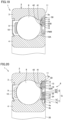
- Fig. 19 is a sectional view of a bearing in a plane including an axis of rotation in a first example of Embodiment 7.
- gas sensor SSR is arranged in through hole 42.
- gas sensor SSR is mounted on the surface of circuit board 13, to which side plate portion 12A is fixed, on the side facing rolling element 8 (similarly to back surface 12b).
- Embodiment 7 is different from Embodiment 5 in which gas sensor SSR is mounted on the surface of circuit board 13 opposite to the side facing rolling element 8 (similarly to front surface 12f).
- porous membrane 41 is formed so as to float relative to through hole 42.
- porous membrane 41 is bonded onto the region of back surface 12b which is adjacent to through hole 42.
- This porous membrane 41 covers through hole 42 from the rolling element 8 side in the axial direction.
- porous membrane 41 has a sectional shape bent with a larger distance from back surface 12b in the region overlapping through hole 42 than in the region on back surface 12b adjacent to through hole 42.
- porous membrane 41 is spaced from through hole 42 in the axial direction so as to cover through hole 42 at a position at which porous membrane 41 overlaps through hole 42 in a planar manner.
Landscapes
- Engineering & Computer Science (AREA)
- General Engineering & Computer Science (AREA)
- Mechanical Engineering (AREA)
- Computer Networks & Wireless Communication (AREA)
Abstract
Description
- The present disclosure relates to a bearing device.
- A bearing device including a sensor provided at a position adjacent to a bearing is used for monitoring the state of a rolling bearing for safety of the device. This bearing device may be configured to wirelessly transmit data detected by the sensor in order to transmit such data with greater convenience.
- For example,
Japanese Patent Laying-Open No. 2017-72170 Japanese Patent Laying-Open No. 2017-72170 - Also,
WO 2017/188314 (PTL 2) discloses an example in which the sensor of the bearing device described above is a gas sensor that detects deterioration of a lubricant used for the bearing. -
- PTL 1:
Japanese Patent Laying-Open No. 2017-72170 - PTL 2:
WO 2017/188314 - In the bearing device of
Japanese Patent Laying-Open No. 2017-72170 - Next, in
WO 2017/188314 , the gas sensor is placed outside a housing that accommodates a bearing while being spaced from the housing. In this case, however, the detection sensitivity of the gas sensor may decrease due to an increased distance between the gas sensor and the bearing. - The present disclosure has been made in view of the above problems. The present disclosure has an object to provide a bearing device that can stably perform wireless transmission of radio waves to outside of a bearing and prevent a decrease in detection sensitivity of a gas sensor.
- A bearing device according to the present disclosure includes a bearing and a retaining member. The bearing includes an outer ring, an inner ring, and a rolling element. The retaining member is fixed to any one ring of the outer ring and the inner ring. The retaining member includes a side plate portion having a width in a radial direction and extending in a circumferential direction. At least part of a power supply that generates electric power and a circuit board are fixed to the retaining member. The circuit board is fixed to, in an axial direction, a surface of the side plate portion not facing the rolling element. At least one gas sensor and a wireless communication circuit are mounted on the circuit board, the at least one gas sensor detecting a state of the bearing, the wireless communication circuit wirelessly transmitting an output of the at least one gas sensor to outside.
- A bearing device according to the present disclosure includes a bearing and a retaining member. The bearing includes an outer ring, an inner ring, and a rolling element. The retaining member is fixed to any one ring of the outer ring and the inner ring. The retaining member includes a side plate portion having a width in a radial direction and extending in a circumferential direction. At least part of a power supply that generates electric power and a circuit board are fixed to the retaining member. The circuit board is fixed to, in an axial direction, a surface of the side plate portion not facing the rolling element. At least one gas sensor and a wireless communication circuit are mounted on the circuit board, the at least one gas sensor detecting a state of the bearing, the wireless communication circuit wirelessly transmitting an output of the at least one gas sensor to outside. The side plate portion has a through hole connecting a first surface facing the rolling element to a second surface located opposite to the first surface. A porous membrane is attached so as to cover the through hole.
- According to the present disclosure, a bearing device can be provided that can stably perform wireless transmission of radio waves to outside of a bearing and prevent a decrease in detection sensitivity of a gas sensor.
-
-
Fig. 1 is a sectional view of a bearing device ofEmbodiment 1. -
Fig. 2 is a perspective view of the entire bearing device ofEmbodiment 2. -
Fig. 3 is a sectional view of a bearing in a plane including an axis of rotation. -
Fig. 4 is a view for describing a retainer. -
Fig. 5 is a view of the bearing device viewed from the sensor unit side. -
Fig. 6 is an exploded perspective view of the sensor unit inEmbodiment 2. -
Fig. 7 is a perspective view of the sensor unit after being assembled inEmbodiment 2. -
Fig. 8 is a perspective view of a sensor unit inEmbodiment 3. -
Fig. 9 is a perspective view of a sensor unit inEmbodiment 4. -
Fig. 10 is a sectional view of a bearing device ofEmbodiment 5. -
Fig. 11 is a perspective view of the entire bearing device ofEmbodiment 6. -
Fig. 12 is a sectional view of a bearing in a plane including an axis of rotation. -
Fig. 13 is a view for describing a retainer. -
Fig. 14 is a view of the bearing device viewed from the sensor unit side. -
Fig. 15 is an exploded perspective view of a sensor unit inEmbodiment 6. -
Fig. 16 is a perspective view of the sensor unit after being assembled inEmbodiment 6. -
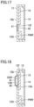
Fig. 17 is an enlarged sectional view of a sensor unit ofFig. 10 inEmbodiment 5. -
Fig. 18 is an enlarged sectional view of a sensor unit ofFig. 19 in Embodiment 7. -
Fig. 19 is a sectional view of a bearing in a plane including an axis of rotation in a first example ofEmbodiment 7. -
Fig. 20 is a sectional view of a bearing in a plane including an axis of rotation in a second example ofEmbodiment 7. - The present embodiment will be described below with reference to the drawings.
-
Fig. 1 is a sectional view of a bearing device ofEmbodiment 1. This corresponds to, for example, a sectional view in a plane including an axis of rotation O inFig. 2 ofEmbodiment 2, which will be described later. The position of each member fixed to a retainingmember 12 inFig. 1 is not necessarily consistent with its actual position. Referring toFig. 1 , abearing device 1 of the present embodiment includes abearing 2 and asensor unit 6. Herein, bearing 2 is a standard bearing having axial dimensions described in a specific standard. The standard bearing is, for example, a bearing having dimensions described in the ISO standard and the JIS standard.Bearing 2 is a radial bearing, and axial dimensions thereof from one end to the other end of bearing 2 are dimensions defined inISO 15 or JISB 1512-1.Bearing 2 will also be referred to asstandard bearing 2 below. -
Bearing 2 includes anouter ring 3, aninner ring 4, a rollingelement 8, aretainer 9, and aseal 10. Inbearing 2, for example,outer ring 3 serves as a stationary ring, andinner ring 4 serves as a rolling ring. Although bearing 2 will be described as a deep-groove ball bearing by way of example, the type ofbearing 2 is not limited to the deep-groove ball bearing.Bearing 2 can be selected from the model number sizes of standard bearings in which a distance W between anend face 11 and rollingelement 8 ofbearing 2 allows accommodation ofsensor unit 6.End face 11 is also the end face ofouter ring 3. - A plurality of rolling
elements 8 are spaced from each other in the circumferential direction of bearing 2 (the depth direction inFig. 1 ). What retains rollingelements 8 isretainer 9.Retainer 9 is a resin member.Retainer 9 is opened on a first end face side (right inFig. 1 ) in the horizontal direction ofFig. 1 , which is the axial direction.Retainer 9 has a shape to be coupled on a second end face side (left inFig. 1 ) in the axial direction. InFig. 1 , thus,retainer 9 is arranged only in approximately the left region relative to the center of rollingelement 8, andretainer 9 is not arranged in the right region relative to the center of rollingelement 8. -
Sensor unit 6 includes a retainingmember 12, acircuit board 13, and alid 14. Retainingmember 12 is a magnetic material and is made of metal. Retainingmember 12 is arranged at a position on the first end face side (right inFig. 1 ) ofretainer 9 relative to rollingelement 8. In other words, retainingmember 12 is arranged, in the axial direction, on the side on whichretainer 9 is opened andretainer 9 is not arranged. Retainingmember 12 is arranged at a position at whichretainer 9 should be originally arranged. - Retaining
member 12 includes aside plate portion 12A.Side plate portion 12A has a width extending fromouter ring 3 toinner ring 4 in the axial direction of bearing 2 (the vertical direction inFig. 1 ).Side plate portion 12A extends in the circumferential direction, that is, so as to draw an annular ring shape. In other words,side plate portion 12A extends continuously (for one round) in the circumferential direction. Retainingmember 12 is formed ofside plate portion 12A, and an outside surface and an inside surface in the radial direction. -
Side plate portion 12A is arranged, at a position (inside in bearing 2) of retainingmember 12 which is axially closest to rollingelement 8, adjacent to rollingelement 8.Side plate portion 12A has aback surface 12b on the side facing rollingelement 8, and afront surface 12f on the side opposite to backsurface 12b (i.e., the side not facing rolling element 8). In other words, backsurface 12b faces the inside of bearing 2, andfront surface 12f faces the outside ofbearing 2. - At least part of a power supply PWR, which can generate electric power, and
circuit board 13 are fixed to retainingmember 12. Power supply PWR ofFig. 1 may be, for example, a power supply in any ofEmbodiments 2 to 4 described later or a power supply of any other type. In other words, power supply PWR ofFig. 1 is a general term for power supplies of every type.Circuit board 13 is fixed tofront surface 12f ofside plate portion 12A of retainingmember 12. - One or more gas sensors SSR that monitor and detect the state of bearing 2 are mounted on
circuit board 13. Gas sensor SSR ofFig. 1 may be of any type. Gas sensor SSR is a general term for sensors that can detect gas. Awireless communication circuit 18 is further mounted oncircuit board 13. - Deterioration (oxidation) of a lubricant used for bearing 2 starts from the reaction that produces an alkyl radical under the influence of light, heat, metal, or the like. An aldehyde, a ketone, a carboxylic acid, an ester, or the like is produced as a primary product and a secondary product. Gas sensor SSR described above may be a sensor of any type that can detect the above-mentioned product. For example, gas sensor SSR may be a gas sensor that can detect a minute amount of carbonyl compound (e.g., formaldehyde, acetaldehyde) with high accuracy, which is a main component of the odor caused when the lubricant of
bearing 2 deteriorates. -
Lid 14 is a non-metallic (resin) sealing member coveringcircuit board 13.Lid 14 protectscircuit board 13 fixed to retainingmember 12 and protects the inside ofsensor unit 6.Circuit board 13 may be sealed with a resin sealing member instead oflid 14. Also,lid 14 protects the member (e.g.,wireless communication circuit 18, gas sensor SSR, or the like) fixed tofront surface 12f ofside plate portion 12A, in addition tocircuit board 13. - The radially-outward outside surface of retaining
member 12 is fitted into, and thus fixed to, a first cut-awayportion 3a formed inouter ring 3. Particularly wheninner ring 4 is a stationary ring, retainingmember 12 may be fixed toinner ring 4. Retainingmember 12 is press-fitted or bonded so as not to extend axially outward beyond end face 11 ofouter ring 3. Retainingmember 12 may be fixed by press-fitting and bonding, or may be fixed by any other method. When retainingmember 12 is fixed to first cut-awayportion 3a, a certain gap is left between rollingelement 8 and retainingmember 12. This can avoid rollingelement 8 and retainingmember 12 from contacting each other owing to the gap also when a displacement occurs axially. - As retaining
member 12 is arranged so as not to extend axially outward beyond end face 11 ofouter ring 3,circuit board 13 and power supply PWR fixed to retainingmember 12 are also arranged so as not to extend axially outward beyond end face 11 ofouter ring 3. Retainingmember 12,circuit board 13, and power supply PWR are preferably arranged so as not to extend axially outward beyond end face 20 ofinner ring 4. -
Bearing device 1 according to the present disclosure includesbearing 2 and retainingmember 12.Bearing 2 includesouter ring 3,inner ring 4, and rollingelement 8. Retainingmember 12 is fixed to any one ring ofouter ring 3 andinner ring 4. Retainingmember 12 includesside plate portion 12A having a width in the radial direction and extending in the circumferential direction. At least part of power supply PWR that can generate electric power andcircuit board 13 are fixed to retainingmember 12.Circuit board 13 is fixed to, in the axial direction, a surface (front surface 12f) ofside plate portion 12A not facing rollingelement 8. At least one gas sensor SSR that detects a state of bearing 2 andwireless communication circuit 18 that wirelessly transmits an output of gas sensor SSR to outside are mounted oncircuit board 13. - Since
circuit board 13 is fixed tofront surface 12f,circuit board 13 is fixed onto retainingmember 12 so as to face the outside ofbearing 2. Thus, even when retainingmember 12 made of a metal having rigidity higher than that of a resin is used, the following problem can be suppressed, for example, a problem of failing to transmit radio waves fromwireless communication circuit 18 or the like mounted oncircuit board 13 to outside of bearing 2 because the radio waves are blocked. In other words, wireless transmission of radio waves to outside of bearing 2 can be performed stably. - Wireless transmission of radio waves to outside of bearing 2 can be performed stably by
wireless communication circuit 18 that receives an output signal of gas sensor SSR and wirelessly transmits the output signal to outside. - According to the present disclosure, thus,
bearing device 1 can be provided that can prevent a decrease in detection sensitivity of gas sensor SSR and can stably perform wireless transmission of radio waves to outside of bearing 2, irrespective of the quality of material of retainingmember 12. - In bearing
device 1 described above, bearing 2 includesretainer 9 includingrolling elements 8 spaced from each other in the circumferential direction.Retainer 9 has a shape to be opened on the first end face side and coupled on the second end face side in the axial direction. Retainingmember 12 is arranged at a position on the first end face side ofretainer 9 relative to rollingelement 8. - In bearing
device 1 described above, since one axial end face ofretainer 9 is opened, a space for arrangingcircuit board 13, power supply PWR, and the like is provided in the opened portion (the portion in whichretainer 9 is originally arranged). In other words, the space for arrangingcircuit board 13 and power supply PWR can be effectively provided insidebearing 2. Also, gas sensor SSR that detects a state of, for example, deterioration of the lubricant of bearing 2 can be arranged in the space described above. Thus, gas sensor SSR can be arranged at a position very close to bearing 2, enabling highly accurate detection of an abnormality of bearing 2 by gas sensor SSR. - What are more prone to oxidation due to, particularly, heat and metal (abrasion powder) are the parts of the lubricant, which are close to
outer ring 3,inner ring 4, and rollingelement 8 ofbearing 2. Thus, when gas sensor SSR is arranged in the space described above, deterioration due to oxidation of the lubricant can be detected with high accuracy. - In bearing
device 1 described above, retainingmember 12 may be made of metal. - Since retaining
member 12 is made of metal, retainingmember 12 can retaincircuit board 13 and gas sensor SSR placed oncircuit board 13 so as to have high rigidity. Accordingly, if retainingmember 12 is directly fixed to vibratingbearing 2, a malfunction of gas sensor SSR can be suppressed. This allows bearingdevice 1 to stably perform monitoring of deterioration of the lubricant by gas sensor SSR and wireless transmission of data detected by gas sensor SSR, even in a use environment in which vibrations are applied. - In the description of a bearing device in each embodiment below, the same components as those of the bearing device of the embodiment described above have the same reference characters allotted, and description thereof will not be repeated unless there is any difference particularly in structure and function. In
Embodiment 2, an electromagnetic generator is used as power supply PWR included in bearingdevice 1 ofEmbodiment 1.Fig. 2 is a perspective view of the entire bearing device ofEmbodiment 2. Referring toFig. 2 ,bearing device 1 includesbearing 2,sensor unit 6, and amagnetic ring 7. -
Sensor unit 6 includes retainingmember 12,circuit board 13,lid 14, and astator 5.Circuit board 13 is fixed to the radially outer region ofside plate portion 12A of retainingmember 12, andstator 5 is arranged so as to entirely include retainingmember 12. -
Lid 14, which is a non-metallic member made of resin, protects the inside ofsensor unit 6.Lid 14 of the present embodiment may be arranged so as to cover the region other thanstator 5, as shown inFig. 3 . Alternatively,lid 14 may be arranged so as to coverstator 5 as well. In any case,lid 14 coverscircuit board 13. -
Stator 5 includes twomagnetic members bobbin 23, and acoil 24. Retainingmember 12 is used asmagnetic member 21 ofstator 5. -
Magnetic ring 7 is a magnetic member with N poles and S poles magnetized alternately in the circumferential direction.Stator 5 is fixed toouter ring 3, andmagnetic ring 7 is fixed toinner ring 4.Stator 5 andmagnetic ring 7 constitute a generator G. Generator G is a craw-pole-type generator and may be a generator of any other structure. The alternate long and short dash line ofFig. 2 is axis of rotation O ofbearing 2. -
Fig. 3 is a sectional view of the bearing in a plane including the axis of rotation. Referring toFig. 3 , stepped first cut-awayportion 3a is formed in the inner circumferential surface ofouter ring 3 at one end as inEmbodiment 1. In the outer circumferential surface ofinner ring 4 at one end, a stepped second cut-awayportion 4a is formed so as to face first cut-awayportion 3a. In the axial direction of bearing 2, anannular recess 50, which is cut out toward rollingelement 8 by first cut-awayportion 3a and second cut-awayportion 4a, is formed overouter ring 3 andinner ring 4. -
Magnetic ring 7 includes acore metal 7a and amultipolar magnet 7b.Multipolar magnet 7b is obtained by, for example, vulcanization bonding of a magnetic material containing kneaded magnetic powder and rubber tocore metal 7a and alternate magnetization of N poles and S poles in the circumferential direction ofbearing 2.Core metal 7a ofmagnetic ring 7 has aflange portion 7c for increased rigidity.Magnetic ring 7 is fixed tooutside surface 4b ofinner ring 4 by, for example, press fitting.Flange portion 7c is fitted in second cut-awayportion 4a formed ininner ring 4.Magnetic ring 7 is disposed so as not to extend beyond end face 20 ofinner ring 4. -
Magnetic ring 7,stator 5, andcircuit board 13 are arranged insideannular recess 50 so as not to overlap each other in the radial direction ofbearing 2. As a result, each component can be arranged insideannular recess 50, resulting in a reduced axial thickness ofbearing 2. Further, in bearingdevice 1, for example,magnetic ring 7 is fixed toinner ring 4, andstator 5 is fixed toouter ring 3 located at the opposite position. Sinceinner ring 4 andouter ring 3 are smaller thanretainer 9 in vibrations in the axial direction of bearing 2, a stable amount of power generation can be achieved by generator G. -
Fig. 4 is a view for describing a retainer. Referring toFig. 4 ,retainer 9 hasrecesses 93 formed at regular pitches in the circumferential direction of end face 91 in the axial direction of an annular retainer body. A pair ofclaw portions recess 93 facing each other in the circumferential direction.Recess 93 and the pair ofclaw portions pocket 95 in which rollingelement 8 shown inFig. 3 is accommodated. As described above,retainer 9 has a shape to be opened on theend face 91 side and coupled on theend face 92 side.Retainer 9, which is a resin member, is arranged to preventsensor unit 6 andmagnetic ring 7 from extending beyondend face 11 and end face 20 to the opening side. -
Fig. 5 is a view of the bearing device viewed from the sensor unit side. InFig. 5 , part oflid 14 is omitted such that the inside ofsensor unit 6 is visible. Referring toFig. 5 , one or more gas sensors SSR that monitor the state of bearing 2 are mounted oncircuit board 13. In addition, for example, anacceleration sensor 15 and atemperature sensor 16 may be mounted oncircuit board 13. Gas sensor SSR may be inserted through a hole (not shown) provided inside plate portion 12A of retainingmember 12 and mounted on the back surface ofcircuit board 13 so as to be closer to (or be in contact with) the end face of first cut-awayportion 3a ofouter ring 3. This allows gas sensor SSR to approachouter ring 3 and accurately detect deterioration of the lubricant ofbearing 2. - A
power supply circuit 17 and awireless communication circuit 18 are further mounted oncircuit board 13.Power supply circuit 17 rectifies alternate-current (AC) power generated by generator G and converts it into direct-current (DC) power. In other words,power supply circuit 17 is totally different from power supply PWR (seeFig. 1 ), that is, generator G (electromagnetic generator) in the present embodiment. Gas sensor SSR,acceleration sensor 15,temperature sensor 16, andwireless communication circuit 18 use the DC power converted bypower supply circuit 17. A terminal 25 is arranged oncircuit board 13. -
Wireless communication circuit 18 includes anantenna portion 18a.Wireless communication circuit 18 wirelessly transmits an output of gas sensor SSR that monitors the state of, for example, deterioration of the lubricant of bearing 2 to outside usingantenna portion 18a.Circuit board 13 is fixed to retainingmember 12 with a plurality ofscrews 19.Circuit board 13 may be fixed to retainingmember 12 by adhesion.Circuit board 13 withwireless communication circuit 18 mounted thereon is arranged to facelid 14 made of resin. Thus,wireless communication circuit 18 has a structure that is not hermitically sealed with a conductive material such as metal. This enables wireless communication usingantenna portion 18a inwireless communication circuit 18. -
Wireless communication circuit 18 includes anoperation unit 18b.Operation unit 18b is, for example, a typically-known central processing unit (CPU) that analyzes the components of a gas detected by gas sensor SSR. For the sake of clarity,operation unit 18b is arranged adjacent to the body ofwireless communication circuit 18 inFig. 5 . However, the present disclosure is not limited to such a manner.Operation unit 18b may be mounted in the body ofwireless communication circuit 18 so as not to be viewed from outside.Operation unit 18b wirelessly transmits data on the gas analysis result received from gas sensor SSR to outside. -
Fig. 6 is an exploded perspective view of the sensor unit inEmbodiment 2.Fig. 7 is a perspective view of the sensor unit after being assembled inEmbodiment 2. Referring toFigs. 6 and 7 ,circuit board 13 is fixed tofront surface 12f ofside plate portion 12A of retainingmember 12 not facing rollingelement 8.Circuit board 13 is arranged in the relatively axially outer region offront surface 12f.Stator 5 includes astator 5A and astator 5B.Stator 5A corresponds to retainingmember 12 and corresponds tomagnetic member 21.Stator 5B corresponds tomagnetic member 22. In other words,stator 5A, retainingmember 12, andmagnetic member 21 are the same, andstator 5B andmagnetic member 22 are the same. -
Magnetic members Magnetic member 21 occupies the entire retainingmember 12, whereasmagnetic member 22 is arranged in the radially inner region of retainingmember 12. The radial inner region of the U-shaped cross section ofmagnetic member 21 faces the U-shaped cross section ofmagnetic member 22. Betweenmagnetic members coil 24 includingbobbin 23 is attached so as to be surrounded bymagnetic members claw portions 21a are formed in the inner circumferential portion ofmagnetic member 21. A plurality ofclaw portions 22a are formed in the inner circumferential portion ofmagnetic member 22.Coil 24 around which a magnet wire is wound several rounds is arranged in a groove provided inbobbin 23 in the circumferential direction.Bobbin 23 may not be provided. - What corresponds to the perspective view of the sensor unit of
Fig. 7 inEmbodiment 1 described above does not includestator 5,claw portions 21a, and clawportions 22a, but basically has a similar aspect to that ofFig. 7 . - The method of assembling
stator 5 will be described below. First, withbobbin 23 around whichcoil 24 is wound being inserted intomagnetic member 22,claw portions 21a ofmagnetic member 21 andclaw portions 22a ofmagnetic member 22 are assembled so as to be alternately spaced from each other in the circumferential direction with a distance in between. Subsequently, an outercircumferential surface 22b ofmagnetic member 22 is fixed such that an end thereof is in contact withfront surface 12f ofside plate portion 12A ofmagnetic member 21. At this time, openings ofmagnetic member 21 andmagnetic member 22 face each other, such thatbobbin 23 andcoil 24 are accommodated in these openings. -
Claw portions 21a ofmagnetic member 21 andclaw portions 22a ofmagnetic member 22 are arranged to face each other with a distance left betweenmultipolar magnet 7b ofmagnetic ring 7, shown inFig. 3 , and the claw portions.Claw portions 21a ofmagnetic member 21 andclaw portions 22a ofmagnetic member 22 instator 5, andmagnetic ring 7 constitute craw-pole-type generator G. The total number ofclaw portions multipolar magnet 7b (the total number of N poles and S poles). - For example, a magnetic flux from the N pole of
multipolar magnet 7b enters magnetic member 21 (or magnetic member 22) fromclaw portions 21a (or clawportions 22a), which are magnetic poles, goes aroundcoil 24, and returns to the S pole ofmultipolar magnet 7b viaadjacent claw portions 22a (or clawportions 21a). The direction of the magnetic flux is reversed as the positions of the N pole and the S pole ofmultipolar magnet 7b are changed by rotation ofinner ring 4. An alternating magnetic field generated as described above generates AC power at the opposite ends ofcoil 24. - The ends (not shown) of
coil 24 drawn fromstator 5, which are the start and end of winding, are connected to terminal 25 provided oncircuit board 13. The AC power output from generator G by the rotation ofinner ring 4 is converted into DC power bypower supply circuit 17. - The region of
sensor unit 6 of bearingdevice 1 may be divided into two in the radial direction of retainingmember 12 by a partition wall (not shown). Also in this case,circuit board 13 is arranged in the radially outer region, andstator 5 of craw-pole-type generator G is arranged in the radially inner region, similarly to the above.Magnetic ring 7 is arranged on the inner diameterside facing stator 5. -
Bearing device 1 of the present embodiment has the following features in addition to the structure ofEmbodiment 1. Power supply PWR (seeFig. 1 ) is an electromagnetic generator (generator G) includingmagnetic ring 7 fixed to the other ring different from the any one ring ofouter ring 3 andinner ring 4, andcoil 24 attached to retainingmember 12 so as to facemagnetic ring 7 in the radial direction ofbearing 2. A plurality of permanent magnets or a magnetic body having a plurality of magnetic poles may be fixed tomagnetic ring 7 asmultipolar magnet 7b. - In bearing
device 1,stator 5 andmagnetic ring 7 radially arranged constitute craw-pole-type generator G. Thus,stator 5 andmagnetic ring 7 can achieve a stable amount of power generation by generator G. The thus generated electric power can be used inwireless communication circuit 18, enabling stable wireless transmission of radio waves to outside ofbearing 2. - In bearing
device 1 according to the present embodiment, only part of the power supply that can generate electric power is fixed to retainingmember 12. Generator G serving as the power supply, which is an electromagnetic generator, includesmagnetic ring 7 andstator 5.Stator 5 is fixed to retainingmember 12. This is because retainingmember 12 isstator 5A, which is part ofstator 5, andbobbin 23 andcoil 24, which constitutestator 5, are fixed to retainingmember 12. On the other hand,magnetic ring 7 facesstator 5 and is fixed to theinner ring 4, which is a rotating ring, side. In other words,magnetic ring 7 is not fixed to retainingmember 12. Thus, only a member of generator G excludingmagnetic ring 7 is fixed to retainingmember 12. - In bearing
device 1 of the present embodiment,wireless communication circuit 18 includesoperation unit 18b.Wireless communication circuit 18 is mounted oncircuit board 13 fixed to retainingmember 12, and retainingmember 12 is fixed to any one ring ofouter ring 3 andinner ring 4 included inbearing 2. Thus,operation unit 18b is arranged in the opened space ofretainer 9.Operation unit 18b wirelessly transmits data on the gas analysis result received from gas sensor SSR to outside. Since gas sensor SSR andoperation unit 18b are both arranged in the opened space ofretainer 9, the distance between gas sensor SSR andoperation unit 18b decreases. This increases the reliability of the data on the gas analysis result transmitted fromoperation unit 18b (wireless communication circuit 18) to outside. This is because data receiving sensitivity increases inoperation unit 18b. -
Fig. 8 is a perspective view of a sensor unit inEmbodiment 3. Referring toFig. 8 , inEmbodiment 3, astorage battery 31 is used as power supply PWR included in bearingdevice 1 ofEmbodiment 1.Storage battery 31 is fixed tofront surface 12f ofside plate portion 12A of retainingmember 12. In other words,storage battery 31 preferably has, for example, an arc planar shape so as to conform to the shape offront surface 12f.Storage battery 31 may be a plurality of storage elements mounted on a substrate.Storage battery 31 corresponds to electromagnetic generator G inEmbodiment 2. Note that generator G generates AC power, whereasstorage battery 31 generates DC power. For this reason,power supply circuit 17 in the present embodiment does not have the function of rectifying AC power to DC power as described inEmbodiment 2.Power supply circuit 17 of the present embodiment controls a voltage value to a target value by stepping up or down a voltage. -
Fig. 9 is a perspective view of a sensor unit inEmbodiment 4. Referring toFig. 9 , inEmbodiment 4, afeeding device 34 including apower reception circuit 32 and apower transmission circuit 33, which transmits a signal topower reception circuit 32 in a contactless manner, is used as power supply PWR included in bearingdevice 1 ofEmbodiment 1.Power reception circuit 32 is fixed tofront surface 12f ofside plate portion 12A of retainingmember 12. In other words, (the substrate of)power reception circuit 32 preferably has, for example, an arc planar shape so as to conform to the shape offront surface 12f. Feedingdevice 34 corresponds tostorage battery 31 inEmbodiment 3 and functions similarly tostorage battery 31. -
Fig. 10 is a sectional view of a bearing device ofEmbodiment 5. This corresponds to a sectional view in a plane including axis of rotation O inFig. 11 ofEmbodiment 6, which will be described later. InFig. 10 , the position of each member fixed to retainingmember 12 is not necessarily consistent with its actual position. Referring toFig. 10 ,bearing device 1 of the present embodiment basically has a similar structure to that of bearingdevice 1 ofFig. 1 described above, and accordingly, the description of matters overlapping those ofEmbodiment 1 will be omitted as appropriate. -
Side plate portion 12A is arranged, at a position axially closest to rollingelement 8 in retaining member 12 (on the inner side in bearing 2), adjacent to rollingelement 8.Side plate portion 12A has backsurface 12b (first surface) on the side facing rollingelement 8 andfront surface 12f (second surface) on the side opposite to backsurface 12b (i.e., the side not facing rolling element 8). In other words, backsurface 12b faces the inside of bearing 2, andfront surface 12f faces the outside ofbearing 2. -
Side plate portion 12A has a throughhole 42 connecting backsurface 12b tofront surface 12f. Throughhole 42 is contiguous to the space adjacent to rollingelement 8 insidebearing 2. Aporous membrane 41 is attached so as to cover throughhole 42. In particular, herein,porous membrane 41 covers throughhole 42 axially from the rollingelement 8 side (backsurface 12b side), thereby closing throughhole 42. In other words,porous membrane 41 closes throughhole 42 in the axial direction. -
Porous membrane 41 mainly contains a fluororesin. In other words,porous membrane 41 is mostly made of the fluororesin though it may contain a trace amount of material other than the fluororesin. The size (the diameter of a largest part) of a hole included inporous membrane 41 is, for example, preferably 10 nm or more and 100 µm or less, and more preferably, 100 nm or more and 10 µm or less. InFig. 10 ,porous membrane 41 is arranged in throughhole 42 so as to close a cross section intersecting the direction (axial direction) of extension of throughhole 42. - At least part of power supply PWR that can generate electric power and
circuit board 13 are fixed to retainingmember 12. Power supply PWR ofFig. 10 may be the power supply in any ofEmbodiments Fig. 10 is a general term for power supplies of every type.Circuit board 13 is fixed tofront surface 12f ofside plate portion 12A of retainingmember 12. - Gas sensor SSR may be, for example, a sensor employing a micro-electro mechanical systems (MEMS) technique. This gas sensor SSR has a structure in which a sensitive film that reacts to a specific gas is supported by a plurality of detection units. In gas sensor SSR, the sensitive film deforms as gas is adsorbed to the sensitive film. Gas sensor SSR detects a gas based on a distortion (a change in electric resistance) of the detection unit induced by the deformation.
- Gas sensor SSR is preferably a gas sensor that detects at least any of an aldehyde and a carboxylic acid with a carbon number of 8 or less.
-
Bearing device 1 according to the present disclosure includesbearing 2 and retainingmember 12.Bearing 2 includesouter ring 3,inner ring 4, and rollingelement 8. Retainingmember 12 is fixed to any one ring ofouter ring 3 andinner ring 4. Retainingmember 12 includesside plate portion 12A having a width in the radial direction and extending in the circumferential direction. At least part of power supply PWR that can generate electric power andcircuit board 13 are fixed to retainingmember 12.Circuit board 13 is fixed to, in the axial direction, the surface (front surface 12f) ofside plate portion 12A not facing rollingelement 8. At least one gas sensor SSR that detects a state of bearing 2 andwireless communication circuit 18 that wirelessly transmits an output of gas sensor SSR to outside are mounted oncircuit board 13.Side plate portion 12A has throughhole 42 that connects the first surface (backsurface 12b) facing rollingelement 8 to the second surface (front surface 12f) located opposite to the first surface and is contiguous to a space adjacent to rollingelement 8.Porous membrane 41 is attached so as to cover throughhole 42. - In bearing
device 1 described above, throughhole 42 may be formed to connect an internal space formed betweenouter ring 3 andinner ring 4 ofbearing 2 to a space in which gas sensor SSR is arranged. The internal space formed betweenouter ring 3 andinner ring 4 is a space in which rollingelement 8 is arranged. - Since
circuit board 13 is fixed tofront surface 12f,circuit board 13 is fixed onto retainingmember 12 so as to face the outside ofbearing 2. For this reason, even when a metallic retaining member having rigidity higher than that of a resin is used as retainingmember 12, the following problem can be suppressed, for example, a problem of failing to transmit radio waves fromwireless communication circuit 18 or the like mounted oncircuit board 13 to outside of bearing 2 because the radio waves are blocked. In other words, wireless transmission of radio waves to outside of bearing 2 can be performed stably. - Wireless transmission of radio waves to outside of bearing 2 can be performed stably by
wireless communication circuit 18 that receives an output signal of gas sensor SSR and wirelessly transmits the output signal to outside. - Further, for example, a gas generated by oxidation of a lubricant in bearing 2 passes through a hole formed in
porous membrane 41.Porous membrane 41 allows the above-mentioned gas of the product to pass therethrough but prevents intrusion of abrasion powder, dust, and oil content intobearing 2. Asporous membrane 41 is attached to throughhole 42 ofside plate portion 12A, only the gas of the product can pass through from the inside of bearing 2 to thefront surface 12f side ofside plate portion 12A. This allows supply of a gas to, for example, gas sensor SSR mounted oncircuit board 13 on thefront surface 12f side. Thus, gas sensor SSR can detect only the gas generated by the lubricant with high accuracy. - Owing to the function of
porous membrane 41 described above, the present embodiment can suppress the following problem, for example, a problem of short-circuit or deterioration ofwireless communication circuit 18 due to intrusion of a metallic foreign body and a lubricant into (e.g.,wireless communication circuit 18 mounted on)circuit board 13 on thefront surface 12f side. - According to the present disclosure, thus,
bearing device 1 can be provided that can prevent a decrease in detection sensitivity of gas sensor SSR and can stably perform wireless transmission of radio waves to outside of bearing 2, irrespective of the quality of material of retainingmember 12. - In bearing
device 1 described above,circuit board 13 is covered withnon-metallic lid 14. This can suppress accidental escape of the gas generated inside bearing 2 from gas sensor SSR after flowing to gas sensor SSR mounted oncircuit board 13. This is becauselid 14 blocks a flow of the gas. As a result, the gas generated inside bearing 2 can be supplied to gas sensor SSR more reliably. This further increases the gas detection sensitivity in gas sensor SSR. - In bearing
device 1 described above,porous membrane 41 is preferably arranged in throughhole 42 so as to close the cross section intersecting the direction of extension of throughhole 42. Consequently, the gas passing throughporous membrane 41 easily flows through throughhole 42 toward gas sensor SSR. - The axial position of
porous membrane 41 in throughhole 42 may be any position. In other words,porous membrane 41 may be arranged on thefront surface 12f side (right) or arranged at the central portion in throughhole 42 inFig. 10 .Porous membrane 41 is more preferably arranged on theback surface 12b side (left) in throughhole 42. Thus,porous membrane 41 is arranged at a position closer toouter ring 3,inner ring 4, and rollingelement 8 insidebearing 2. Consequently, the gas generated by the lubricant or the like insidebearing 2 reachesporous membrane 41 more easily. This facilitates inflow of the gas fromporous membrane 41 into throughhole 42 and toward gas sensor SSR. - In bearing
device 1 described above, preferably,porous membrane 41 mainly contains a fluororesin. Thus,porous membrane 41 allows only the gas generated by oxidation of the lubricant of bearing 2 to flow therethrough and allows inflow of the gas toward gas sensor SSR mounted oncircuit board 13. In other words,porous membrane 41 prevents intrusion of abrasion powder, dust, and oil content inside bearing 2 to gas sensor SSR andwireless communication circuit 18 oncircuit board 13. - In bearing
device 1 described above, gas sensor SSR detects at least any of an aldehyde and a carboxylic acid with a carbon number of 8 or less. Specifically, what is detected by gas sensor SSR is preferably a gas of each compound shown in Table 1 (chain aliphatic aldehydes) and Table 2 (carboxylic acids) below.[Table 1] Name Molecular formula Boiling point (°C) Formaldehyde CH2O -19.3 Acetaldehyde C2H4O 20.2 Propionaldehyde C3H6O 48 Butylaldehyde C4H8O 85 Valeraldehyde C5H10O 103 Hexanal C6H12O 129 Heptanal C7H14O 153 Octanal C8H16O 171 [Table 2] Name Molecular formula Boiling point (°C) Formic acid CH2O2 101 Acetic acid C2H4O2 141 Propionic acid C3H6O2 141 Butyric acid C4H8O2 163 - Tables 1 and 2 show chain aliphatic aldehydes and carboxylic acids having a low molecular weight. In these compounds, a compound with a smaller carbon number has a lower boiling point (i.e., volatiles more easily). Thus, the gas of the compound with a small carbon number is suitable for a target to be detected by a gas sensor. The temperature conditions on which
bearing 2 is used are varied. A typical material for the rolling bearing is SUJ2, which is carbon steel for bearings. The allowable upper-limit temperature of a bearing produced by a standard heat treatment of SUJ2 is approximately 120°C. However, the bearing can be used at 200°C or higher temperature by being subjected to dimensional stabilization. Considering such operating conditions for typical bearings, an aldehyde and a carboxylic acid with a carbon number of 8 or less are particularly suitable as a target product for detecting oxidation of a lubricant. - In bearing
device 1 described above, bearing 2 includesretainer 9retaining rolling elements 8 at intervals in the circumferential direction.Retainer 9 has a shape to be opened on the first end face side and coupled on the second end face side in the axial direction. Retainingmember 12 is arranged at a position on the first end face side ofretainer 9 relative to rollingelement 8. - In bearing
device 1 described above, since one axial end face ofretainer 9 is opened, a space in whichcircuit board 13, power supply PWR, and the like are arranged is provided in the opened portion (the portion in whichretainer 9 is originally arranged). In other words, the space for arrangingcircuit board 13 and power supply PWR is effectively provided insidebearing 2. Also, gas sensor SSR that detects the state of, for example, deterioration of the lubricant of bearing 2 can be arranged in the space described above. Thus, gas sensor SSR can be arranged at a position very close to bearing 2, enabling highly accurate detection of an abnormality of bearing 2 by gas sensor SSR. - What are more prone to oxidation due to, particularly, heat and metal (abrasion powder) are the parts of the lubricant, which are close to
outer ring 3,inner ring 4, and rollingelement 8 ofbearing 2. Thus, when gas sensor SSR is arranged in the space described above, deterioration due to oxidation of the lubricant can be detected with high accuracy. - In bearing
device 1 described above, retainingmember 12 may be made of metal. - Since retaining
member 12 is made of metal, retainingmember 12 can retaincircuit board 13 and gas sensor SSR placed oncircuit board 13 so as to have high rigidity. Accordingly, if retainingmember 12 is directly fixed to vibratingbearing 2, a malfunction of gas sensor SSR can be suppressed. This allows bearingdevice 1 to stably perform monitoring of deterioration of the lubricant by gas sensor SSR and wireless transmission of data detected by gas sensor SSR, even in a use environment in which vibrations are applied. - In the description of the bearing device in each embodiment described below, the same components as those of the bearing device of the embodiment described above have the same reference characters allotted, and description thereof will not be repeated unless there is any difference particularly in structure and function. In
Embodiment 6, an electromagnetic generator is used as power supply PWR included in bearingdevice 1 ofEmbodiment 5.Fig. 11 is a perspective view of the entire bearing device ofEmbodiment 6. Referring toFig. 11 ,bearing device 1 includesbearing 2,sensor unit 6, andmagnetic ring 7. SinceFig. 11 shows components similar to those ofFig. 2 , description of the matters overlapping those ofFig. 2 will be omitted as appropriate. -
Lid 14, which is a non-metallic member made of resin, protects the inside ofsensor unit 6.Lid 14 of the present embodiment may be arranged so as to cover the region other thanstator 5 as inFig. 12 . Alternatively,lid 14 may be arranged so as to coverstator 5 as well. In any case,lid 14 coverscircuit board 13. In order to increase gas detection sensitivity by gas sensor SSR, the distance between gas sensor SSR and throughhole 42 is preferably smaller. For this reason,Fig. 12 , which will be described next, shows gas sensor SSR at the position ofwireless communication circuit 18 in the other figures. However, the position of each member in retainingmember 12 does not necessarily indicate its actual position inFig. 12 and the following sectional views, similarly toFig. 10 . -
Fig. 12 is a sectional view of a bearing in a plane including an axis of rotation. Referring toFig. 12 , stepped first cut-awayportion 3a is formed in the inner circumferential surface ofouter ring 3 at one end, as inEmbodiment 5. Further, stepped second cut-awayportion 4a is formed in the outer circumferential surface ofinner ring 4 at one end so as to face first cut-awayportion 3a. In the axial direction of bearing 2,annular recess 50, which is cut out toward rollingelement 8 by first cut-awayportion 3a and second cut-awayportion 4a, is formed overouter ring 3 andinner ring 4. SinceFig. 12 basically shows components similar to those ofFig. 3 except thatporous membrane 41 and throughhole 42 are provided, description of the overlapping matters will not be repeated. -
Fig. 13 is a view for describing a retainer.Fig. 13 shows similar components to those ofFig. 4 , and accordingly, description thereof will not be repeated. -
Fig. 14 is a view of a bearing device viewed from the sensor unit side. InFig. 14 , part oflid 14 is omitted such that the inside ofsensor unit 6 is visible. Referring toFig. 14 , one or more gas sensors SSR that monitor the state of bearing 2 are mounted oncircuit board 13. In addition, for example,acceleration sensor 15 andtemperature sensor 16 may be mounted oncircuit board 13. SinceFig. 14 basically shows similar components to those ofFig. 5 except thatporous membrane 41 and throughhole 42 are provided, description of the overlapping matters will not be repeated. -
Fig. 15 is an exploded perspective view of a sensor unit inEmbodiment 6.Fig. 16 is a perspective view of the sensor unit after being assembled inEmbodiment 6. SinceFigs. 15 and 16 basically show similar components to those ofFigs. 6 and 7 except thatporous membrane 41 and throughhole 42 are provided, description thereof will not be repeated. - The method of assembling
stator 5 is similar to that ofEmbodiment 2 described above, and accordingly, description thereof will not be repeated. - Similarly to
Embodiment 5, the present embodiment includesporous membrane 41 and throughhole 42 and exhibits similar functions and effects to those ofEmbodiment 5. In other words,circuit board 13 is covered withnon-metallic lid 14. This can suppress accidental escape of the gas generated inside bearing 2 from gas sensor SSR after flowing to gas sensor SSR mounted oncircuit board 13. This is becauselid 14 blocks a flow of the gas. - In bearing
device 1 of the present embodiment, power supply PWR (seeFig. 10 ) is an electromagnetic generator (generator G) includingmagnetic ring 7 fixed to the other ring different from the any one ring ofouter ring 3 andinner ring 4, andcoil 24 attached to retainingmember 12 so as to facemagnetic ring 7 in the radial direction ofbearing 2. A plurality of permanent magnets or a magnetic body having a plurality of magnetic poles may be fixed tomagnetic ring 7 asmultipolar magnet 7b. -
Stator 5 andmagnetic ring 7 radially arranged in bearingdevice 1 constitute craw-pole-type generator G. Thus,stator 5 andmagnetic ring 7 can achieve a stable amount of power generation by generator G. The thus generated electric power can be used inwireless communication circuit 18, enabling stable wireless transmission of radio waves to outside ofbearing 2. - In bearing
device 1 according to the present embodiment, only part of the power supply that can generate electric power is fixed to retainingmember 12. Generator G serving as the power supply, which is an electromagnetic generator, includesmagnetic ring 7 andstator 5.Stator 5 is fixed to retainingmember 12. This is because retainingmember 12 isstator 5A, which is part ofstator 5, andbobbin 23 andcoil 24, which constitutestator 5, are fixed to retainingmember 12. On the other hand,magnetic ring 7 facesstator 5 and is fixed to theinner ring 4, which is a rotating ring, side. In other words,magnetic ring 7 is not fixed to retainingmember 12. Thus, only a member of generator G excludingmagnetic ring 7 is fixed to retainingmember 12. - In bearing
device 1 of the present embodiment,wireless communication circuit 18 includesoperation unit 18b.Wireless communication circuit 18 is mounted oncircuit board 13 fixed to retainingmember 12, and retainingmember 12 is fixed to any one ring ofouter ring 3 andinner ring 4 included inbearing 2. Thus,operation unit 18b is arranged in the opened space ofretainer 9.Operation unit 18b wirelessly transmits data on the gas analysis result received from gas sensor SSR to outside. Since gas sensor SSR andoperation unit 18b are both arranged in the opened space ofretainer 9, the distance between gas sensor SSR andoperation unit 18b decreases. This increases the reliability of the data on the gas analysis result transmitted fromoperation unit 18b (wireless communication circuit 18) to outside. This is because data receiving sensitivity increases inoperation unit 18b. -
Fig. 17 is an enlarged sectional view of a sensor unit ofFig. 10 inEmbodiment 5.Fig. 18 is an enlarged sectional view a sensor unit ofFig. 19 inEmbodiment 7. Referring toFigs. 17 and 18 ,Embodiment 5 andEmbodiment 7 are similar in that throughhole 42 passing throughside plate portion 12A fromback surface 12b tofront surface 12f is formed and thatporous membrane 41 is attached so as to cover throughhole 42 in the axial direction. However,porous membrane 41 is arranged within throughhole 42 inEmbodiment 5, whereasporous membrane 41 is spaced from throughhole 42 outside of throughhole 42 inEmbodiment 7.Embodiment 7 is different fromEmbodiment 5 in this point. -
Fig. 19 is a sectional view of a bearing in a plane including an axis of rotation in a first example ofEmbodiment 7. Referring toFig. 19 , inEmbodiment 7, gas sensor SSR is arranged in throughhole 42. To that end, gas sensor SSR is mounted on the surface ofcircuit board 13, to whichside plate portion 12A is fixed, on the side facing rolling element 8 (similarly to backsurface 12b). In this respect,Embodiment 7 is different fromEmbodiment 5 in which gas sensor SSR is mounted on the surface ofcircuit board 13 opposite to the side facing rolling element 8 (similarly tofront surface 12f). - In the present embodiment,
porous membrane 41 is formed so as to float relative to throughhole 42. In other words,porous membrane 41 is bonded onto the region ofback surface 12b which is adjacent to throughhole 42. Thisporous membrane 41 covers throughhole 42 from the rollingelement 8 side in the axial direction. Note thatporous membrane 41 has a sectional shape bent with a larger distance fromback surface 12b in the region overlapping throughhole 42 than in the region onback surface 12b adjacent to throughhole 42. Thus,porous membrane 41 is spaced from throughhole 42 in the axial direction so as to cover throughhole 42 at a position at whichporous membrane 41 overlaps throughhole 42 in a planar manner. -
Fig. 20 is a sectional view of a bearing in a plane including an axis of rotation in a second example ofEmbodiment 7. Referring toFig. 20 , power supply PWR similar to that ofFig. 10 is shown in the first example ofFig. 19 , whereas craw-pole-type generator G similar to that ofFig. 12 is used in the second example ofFig. 20 .Porous membrane 41 and gas sensor SSR ofFig. 20 are similar to those ofFig. 19 . - As in each example of the present embodiment, gas sensor SSR may be inserted through through
hole 42 provided inside plate portion 12A of retainingmember 12 and mounted on the back surface (the surface facing rollingelement 8 inside bearing 2) ofcircuit board 13 so as to be close to (or be in contact with) the end face of first cut-awayportion 3a ofouter ring 3. This causes gas sensor SSR to approachouter ring 3, enabling accurate detection of deterioration of the lubricant ofbearing 2. The functions and effects achieved byporous membrane 41 are similar to those ofEmbodiments - The features described in (the examples included in) the respective embodiments described above may be applied in combination as appropriate within the range where there is no technical inconsistency.
- It is to be understood that the embodiments disclosed herein are presented for the purpose of illustration and non-restrictive in every respect. It is therefore intended that the scope of the present invention is defined by claims, not only by the embodiments described above, and encompasses all modifications and variations equivalent in meaning and scope to the claims.
- 1 bearing device; 2 bearing; 3 outer ring; 3a first cut-away portion; 4 inner ring; 4a second cut-away portion; 4b outside surface; 5, 5A, 5B stator; 6 sensor unit; 7 magnetic ring; 7a core metal; 7b multipolar magnet; 7c flange portion; 8 rolling element; 9 retainer; 10 seal; 11, 20, 91, 92 end face; 12 retaining member; 12A side plate portion; 12b back surface; 12f front surface; 13 circuit board; 14 lid; 15 acceleration sensor; 16 temperature sensor; 17 power supply circuit; 18 wireless communication circuit; 18a antenna portion; 18b operation unit; 19 screw; 21, 22 magnetic member; 21a, 22a claw portion; 23 bobbin; 24 coil; 25 terminal; 31 storage battery; 41 porous membrane; 42 through hole; 50 annular recess; 93 recess; 94 claw portion; 95 pocket; PWR power supply; SSR gas sensor.
Claims (15)
- A bearing device comprising:a bearing including an outer ring, an inner ring, and a rolling element; anda retaining member, whereinthe retaining member is fixed to any one ring of the outer ring and the inner ring,the retaining member includes a side plate portion having a width in a radial direction and extending in a circumferential direction,at least part of a power supply that generates electric power and a circuit board are fixed to the retaining member,the circuit board is fixed to, in an axial direction, a surface of the side plate portion not facing the rolling element, andat least one gas sensor and a wireless communication circuit are mounted on the circuit board, the at least one gas sensor detecting a state of the bearing, the wireless communication circuit wirelessly transmitting an output of the at least one gas sensor to outside.
- The bearing device according to claim 1, wherein the wireless communication circuit includes an operation unit.
- The bearing device according to claim 1 or 2, wherein the power supply is an electromagnetic generator includinga magnetic ring fixed to the other ring different from the any one ring of the outer ring and the inner ring, anda coil attached to the retaining member so as to face the magnetic ring in a radial direction of the bearing.
- The bearing device according to claim 1 or 2, wherein the power supply is a storage battery.
- The bearing device according to claim 1 or 2, whereinthe power supply is a feeding device including a power reception circuit and a power transmission circuit that transmits a signal to the power reception circuit in a contactless manner, andthe power reception circuit is mounted on the retaining member.
- The bearing device according to any one of claims 1 to 5, whereinthe bearing further includes a retainer retaining a plurality of the rolling elements at intervals in the circumferential direction,the retainer has a shape to be opened on a first end face side and coupled on a second end face side in the axial direction, andthe retaining member is arranged at a position on the first end face side of the retainer relative to the rolling element.
- The bearing device according to any one of claims 1 to 6, wherein the retaining member is made of metal.
- A bearing device comprising:a bearing including an outer ring, an inner ring, and a rolling element; anda retaining member, whereinthe retaining member is fixed to any one ring of the outer ring and the inner ring,the retaining member includes a side plate portion having a width in a radial direction and extending in a circumferential direction,at least part of a power supply that generates electric power and a circuit board are fixed to the retaining member,the circuit board is fixed to, in an axial direction, a surface of the side plate portion of the retaining member not facing the rolling element,at least one gas sensor and a wireless communication circuit are mounted on the circuit board, the at least one gas sensor detecting a state of the bearing, the wireless communication circuit wirelessly transmitting an output of the at least one gas sensor to outside,the side plate portion has a through hole connecting a first surface facing the rolling element to a second surface located opposite to the first surface, anda porous membrane is attached so as to cover the through hole.
- The bearing device according to claim 8, wherein the circuit board is covered with a non-metallic lid.
- The bearing device according to claim 8 or 9, wherein the porous membrane is arranged in the through hole so as to close a cross section intersecting a direction of extension of the through hole.
- The bearing device according to claim 8 or 9, whereinthe gas sensor is arranged in the through hole, andthe porous membrane is spaced from the through hole so as to cover the through hole at a position at which the porous membrane overlaps the through hole in a planar manner.
- The bearing device according to any one of claims 8 to 11, wherein the porous membrane mainly contains a fluororesin.
- The bearing device according to any one of claims 8 to 12,
wherein the gas sensor detects at least any of an aldehyde and a carboxylic acid with a carbon number of 8 or less. - The bearing device according to any one of claims 8 to 13, whereinthe bearing further includes a retainer retaining a plurality of the rolling elements at intervals in the circumferential direction,the retainer has a shape to be opened on a first end face side and coupled on a second end face side in the axial direction, andthe retaining member is arranged at a position on the first end face side of the retainer relative to the rolling element.
- The bearing device according to any one of claims 8 to 14, wherein the retaining member is made of metal.
Applications Claiming Priority (3)
| Application Number | Priority Date | Filing Date | Title |
|---|---|---|---|
| JP2022055790A JP7814217B2 (en) | 2022-03-30 | 2022-03-30 | Bearing device |
| JP2022055789A JP7814216B2 (en) | 2022-03-30 | 2022-03-30 | Bearing device |
| PCT/JP2023/008532 WO2023189277A1 (en) | 2022-03-30 | 2023-03-07 | Bearing device |
Publications (2)
| Publication Number | Publication Date |
|---|---|
| EP4502407A1 true EP4502407A1 (en) | 2025-02-05 |
| EP4502407A4 EP4502407A4 (en) | 2025-07-09 |
Family
ID=88201347
Family Applications (1)
| Application Number | Title | Priority Date | Filing Date |
|---|---|---|---|
| EP23779304.7A Pending EP4502407A4 (en) | 2022-03-30 | 2023-03-07 | STORAGE DEVICE |
Country Status (3)
| Country | Link |
|---|---|
| US (1) | US20250215934A1 (en) |
| EP (1) | EP4502407A4 (en) |
| WO (1) | WO2023189277A1 (en) |
Family Cites Families (16)
| Publication number | Priority date | Publication date | Assignee | Title |
|---|---|---|---|---|
| JP2002206528A (en) * | 2000-11-06 | 2002-07-26 | Nsk Ltd | Rolling bearing with sensor |
| EP1203960B2 (en) * | 2000-11-06 | 2018-02-07 | Nsk Ltd | Rolling bearing device and ring with sensor for the rolling bearing device |
| JP4029604B2 (en) * | 2001-11-29 | 2008-01-09 | 日本精工株式会社 | Rolling bearing |
| JP4281319B2 (en) * | 2002-10-10 | 2009-06-17 | 株式会社ジェイテクト | Rolling bearing device |
| JP2005030588A (en) * | 2004-05-10 | 2005-02-03 | Ntn Corp | Abnormality checking system for bearing with ic tag sensor in conveyor |
| JP4530888B2 (en) * | 2005-03-18 | 2010-08-25 | Ntn株式会社 | Antenna mounting structure of bearing with antenna |
| JP2009172519A (en) * | 2008-01-24 | 2009-08-06 | Toyota Motor Corp | Filter device, waterproof case in which filter device is installed, and method for removing hematite trapped in porous membrane |
| DE102010021158A1 (en) * | 2010-05-21 | 2011-11-24 | Schaeffler Technologies Gmbh & Co. Kg | Rolling bearing with integrated generator and method for energy management of such a rolling bearing |
| JP2012130885A (en) * | 2010-12-22 | 2012-07-12 | Asahi Glass Co Ltd | Oil-repellent waterproof air-permeable filter and method for producing the same |
| JP2012163506A (en) * | 2011-02-09 | 2012-08-30 | Gunze Ltd | In-oil hydrogen detection sensor |
| DE102012215582A1 (en) * | 2012-09-03 | 2014-03-06 | Schaeffler Technologies AG & Co. KG | Bearing such as wheelset bearings of rail vehicles for guiding mutually movable components has sensor holder that is formed such that detection portion of sensor is arranged in a portion of interior of housing in assembly position of sensor |
| JP6743361B2 (en) | 2015-10-06 | 2020-08-19 | 日本精工株式会社 | Bearing with wireless sensor |
| US10890575B2 (en) * | 2016-04-28 | 2021-01-12 | Nsk Ltd. | Lubricant deterioration detection device and lubricant deterioration state evaluation method |
| JP7155583B2 (en) * | 2018-03-30 | 2022-10-19 | 日本精工株式会社 | Generating units with sensors and bearings with sensors |
| JP7452369B2 (en) * | 2019-10-10 | 2024-03-19 | 日本精工株式会社 | Bearings with sensors and sensor units |
| JP7731204B2 (en) * | 2020-02-14 | 2025-08-29 | Ntn株式会社 | Bearing device, spacer and manufacturing method |
-
2023
- 2023-03-07 US US18/851,228 patent/US20250215934A1/en active Pending
- 2023-03-07 EP EP23779304.7A patent/EP4502407A4/en active Pending
- 2023-03-07 WO PCT/JP2023/008532 patent/WO2023189277A1/en not_active Ceased
Also Published As
| Publication number | Publication date |
|---|---|
| US20250215934A1 (en) | 2025-07-03 |
| WO2023189277A1 (en) | 2023-10-05 |
| EP4502407A4 (en) | 2025-07-09 |
Similar Documents
| Publication | Publication Date | Title |
|---|---|---|
| US6892587B2 (en) | Rotation detecting device and wheel support bearing assembly utilizing the same | |
| US6838794B2 (en) | Bearing assembly with electric power generator | |
| US20170040874A1 (en) | Sensor assembly and motor including the same | |
| WO2015032449A1 (en) | Bearing assembly including a sensor roller | |
| JP2005140320A5 (en) | ||
| US20150093271A1 (en) | Brushless motor and fan using the motor | |
| US20210384796A1 (en) | Motor | |
| US20120013329A1 (en) | Rotation sensor device for wheel | |
| US11441675B2 (en) | Inhibitor integrated actuator shift control device | |
| WO2011027482A1 (en) | Rotation detecting apparatus | |
| US20250215934A1 (en) | Bearing Device | |
| JP2009296718A (en) | Motor equipped with resolver | |
| JP7814217B2 (en) | Bearing device | |
| JP7814216B2 (en) | Bearing device | |
| EP4484778B1 (en) | Bearing device | |
| JP2003262647A (en) | Rotation detector and bearing unit for wheel mounting the same | |
| CN118922643A (en) | Bearing device | |
| US20240159276A1 (en) | Resolver integrated-type bearing device and method for manufacturing same | |
| EP4585820A1 (en) | Bearing device | |
| JP2006349073A (en) | Bearing for electromagnetic clutch | |
| CN223678517U (en) | Probe assembly for a sensor and sensor | |
| JP2025147610A (en) | Bearing device and abnormality detection system | |
| JP7450657B2 (en) | bearing device | |
| US20240063693A1 (en) | Motor | |
| JP2026012858A (en) | Bearing device |
Legal Events
| Date | Code | Title | Description |
|---|---|---|---|
| STAA | Information on the status of an ep patent application or granted ep patent |
Free format text: STATUS: THE INTERNATIONAL PUBLICATION HAS BEEN MADE |
|
| PUAI | Public reference made under article 153(3) epc to a published international application that has entered the european phase |
Free format text: ORIGINAL CODE: 0009012 |
|
| STAA | Information on the status of an ep patent application or granted ep patent |
Free format text: STATUS: REQUEST FOR EXAMINATION WAS MADE |
|
| 17P | Request for examination filed |
Effective date: 20241011 |
|
| AK | Designated contracting states |
Kind code of ref document: A1 Designated state(s): AL AT BE BG CH CY CZ DE DK EE ES FI FR GB GR HR HU IE IS IT LI LT LU LV MC ME MK MT NL NO PL PT RO RS SE SI SK SM TR |
|
| A4 | Supplementary search report drawn up and despatched |
Effective date: 20250612 |
|
| DAV | Request for validation of the european patent (deleted) | ||
| DAX | Request for extension of the european patent (deleted) | ||
| RIC1 | Information provided on ipc code assigned before grant |
Ipc: F16C 19/52 20060101ALI20250605BHEP Ipc: F16C 19/06 20060101AFI20250605BHEP Ipc: G01N 33/28 20060101ALI20250605BHEP Ipc: G01N 33/00 20060101ALI20250605BHEP Ipc: F16N 29/04 20060101ALI20250605BHEP Ipc: F16N 29/00 20060101ALI20250605BHEP Ipc: F16C 33/66 20060101ALI20250605BHEP Ipc: G08C 17/02 20060101ALI20250605BHEP Ipc: G08C 17/00 20060101ALI20250605BHEP Ipc: F16C 41/00 20060101ALI20250605BHEP Ipc: F16C 33/78 20060101ALI20250605BHEP Ipc: F16C 33/41 20060101ALI20250605BHEP |
|
| STAA | Information on the status of an ep patent application or granted ep patent |
Free format text: STATUS: EXAMINATION IS IN PROGRESS |
|
| 17Q | First examination report despatched |
Effective date: 20251208 |