EP4502391A1 - Axial fan - Google Patents
Axial fan Download PDFInfo
- Publication number
- EP4502391A1 EP4502391A1 EP23779542.2A EP23779542A EP4502391A1 EP 4502391 A1 EP4502391 A1 EP 4502391A1 EP 23779542 A EP23779542 A EP 23779542A EP 4502391 A1 EP4502391 A1 EP 4502391A1
- Authority
- EP
- European Patent Office
- Prior art keywords
- section
- edge
- leading edge
- porous part
- rotation direction
- Prior art date
- Legal status (The legal status is an assumption and is not a legal conclusion. Google has not performed a legal analysis and makes no representation as to the accuracy of the status listed.)
- Pending
Links
Images


Classifications
-
- F—MECHANICAL ENGINEERING; LIGHTING; HEATING; WEAPONS; BLASTING
- F04—POSITIVE - DISPLACEMENT MACHINES FOR LIQUIDS; PUMPS FOR LIQUIDS OR ELASTIC FLUIDS
- F04D—NON-POSITIVE-DISPLACEMENT PUMPS
- F04D29/00—Details, component parts, or accessories
- F04D29/66—Combating cavitation, whirls, noise, vibration or the like; Balancing
- F04D29/661—Combating cavitation, whirls, noise, vibration or the like; Balancing especially adapted for elastic fluid pumps
- F04D29/666—Combating cavitation, whirls, noise, vibration or the like; Balancing especially adapted for elastic fluid pumps by means of rotor construction or layout, e.g. unequal distribution of blades or vanes
-
- F—MECHANICAL ENGINEERING; LIGHTING; HEATING; WEAPONS; BLASTING
- F04—POSITIVE - DISPLACEMENT MACHINES FOR LIQUIDS; PUMPS FOR LIQUIDS OR ELASTIC FLUIDS
- F04D—NON-POSITIVE-DISPLACEMENT PUMPS
- F04D19/00—Axial-flow pumps
- F04D19/002—Axial flow fans
-
- F—MECHANICAL ENGINEERING; LIGHTING; HEATING; WEAPONS; BLASTING
- F04—POSITIVE - DISPLACEMENT MACHINES FOR LIQUIDS; PUMPS FOR LIQUIDS OR ELASTIC FLUIDS
- F04D—NON-POSITIVE-DISPLACEMENT PUMPS
- F04D29/00—Details, component parts, or accessories
- F04D29/02—Selection of particular materials
- F04D29/023—Selection of particular materials especially adapted for elastic fluid pumps
-
- F—MECHANICAL ENGINEERING; LIGHTING; HEATING; WEAPONS; BLASTING
- F04—POSITIVE - DISPLACEMENT MACHINES FOR LIQUIDS; PUMPS FOR LIQUIDS OR ELASTIC FLUIDS
- F04D—NON-POSITIVE-DISPLACEMENT PUMPS
- F04D29/00—Details, component parts, or accessories
- F04D29/26—Rotors specially for elastic fluids
- F04D29/32—Rotors specially for elastic fluids for axial flow pumps
- F04D29/38—Blades
-
- F—MECHANICAL ENGINEERING; LIGHTING; HEATING; WEAPONS; BLASTING
- F04—POSITIVE - DISPLACEMENT MACHINES FOR LIQUIDS; PUMPS FOR LIQUIDS OR ELASTIC FLUIDS
- F04D—NON-POSITIVE-DISPLACEMENT PUMPS
- F04D29/00—Details, component parts, or accessories
- F04D29/26—Rotors specially for elastic fluids
- F04D29/32—Rotors specially for elastic fluids for axial flow pumps
- F04D29/38—Blades
- F04D29/384—Blades characterised by form
-
- F—MECHANICAL ENGINEERING; LIGHTING; HEATING; WEAPONS; BLASTING
- F04—POSITIVE - DISPLACEMENT MACHINES FOR LIQUIDS; PUMPS FOR LIQUIDS OR ELASTIC FLUIDS
- F04D—NON-POSITIVE-DISPLACEMENT PUMPS
- F04D29/00—Details, component parts, or accessories
- F04D29/26—Rotors specially for elastic fluids
- F04D29/32—Rotors specially for elastic fluids for axial flow pumps
- F04D29/38—Blades
- F04D29/388—Blades characterised by construction
-
- F—MECHANICAL ENGINEERING; LIGHTING; HEATING; WEAPONS; BLASTING
- F04—POSITIVE - DISPLACEMENT MACHINES FOR LIQUIDS; PUMPS FOR LIQUIDS OR ELASTIC FLUIDS
- F04D—NON-POSITIVE-DISPLACEMENT PUMPS
- F04D29/00—Details, component parts, or accessories
- F04D29/66—Combating cavitation, whirls, noise, vibration or the like; Balancing
- F04D29/661—Combating cavitation, whirls, noise, vibration or the like; Balancing especially adapted for elastic fluid pumps
- F04D29/663—Sound attenuation
- F04D29/664—Sound attenuation by means of sound absorbing material
-
- F—MECHANICAL ENGINEERING; LIGHTING; HEATING; WEAPONS; BLASTING
- F04—POSITIVE - DISPLACEMENT MACHINES FOR LIQUIDS; PUMPS FOR LIQUIDS OR ELASTIC FLUIDS
- F04D—NON-POSITIVE-DISPLACEMENT PUMPS
- F04D29/00—Details, component parts, or accessories
- F04D29/66—Combating cavitation, whirls, noise, vibration or the like; Balancing
- F04D29/68—Combating cavitation, whirls, noise, vibration or the like; Balancing by influencing boundary layers
- F04D29/681—Combating cavitation, whirls, noise, vibration or the like; Balancing by influencing boundary layers especially adapted for elastic fluid pumps
- F04D29/682—Combating cavitation, whirls, noise, vibration or the like; Balancing by influencing boundary layers especially adapted for elastic fluid pumps by fluid extraction
-
- F—MECHANICAL ENGINEERING; LIGHTING; HEATING; WEAPONS; BLASTING
- F04—POSITIVE - DISPLACEMENT MACHINES FOR LIQUIDS; PUMPS FOR LIQUIDS OR ELASTIC FLUIDS
- F04D—NON-POSITIVE-DISPLACEMENT PUMPS
- F04D29/00—Details, component parts, or accessories
- F04D29/66—Combating cavitation, whirls, noise, vibration or the like; Balancing
- F04D29/68—Combating cavitation, whirls, noise, vibration or the like; Balancing by influencing boundary layers
- F04D29/681—Combating cavitation, whirls, noise, vibration or the like; Balancing by influencing boundary layers especially adapted for elastic fluid pumps
- F04D29/684—Combating cavitation, whirls, noise, vibration or the like; Balancing by influencing boundary layers especially adapted for elastic fluid pumps by fluid injection
-
- F—MECHANICAL ENGINEERING; LIGHTING; HEATING; WEAPONS; BLASTING
- F24—HEATING; RANGES; VENTILATING
- F24F—AIR-CONDITIONING; AIR-HUMIDIFICATION; VENTILATION; USE OF AIR CURRENTS FOR SCREENING
- F24F1/00—Room units for air-conditioning, e.g. separate or self-contained units or units receiving primary air from a central station
- F24F1/06—Separate outdoor units, e.g. outdoor unit to be linked to a separate room comprising a compressor and a heat exchanger
- F24F1/38—Fan details of outdoor units, e.g. bell-mouth shaped inlets or fan mountings
-
- F—MECHANICAL ENGINEERING; LIGHTING; HEATING; WEAPONS; BLASTING
- F05—INDEXING SCHEMES RELATING TO ENGINES OR PUMPS IN VARIOUS SUBCLASSES OF CLASSES F01-F04
- F05D—INDEXING SCHEME FOR ASPECTS RELATING TO NON-POSITIVE-DISPLACEMENT MACHINES OR ENGINES, GAS-TURBINES OR JET-PROPULSION PLANTS
- F05D2240/00—Components
- F05D2240/20—Rotors
- F05D2240/30—Characteristics of rotor blades, i.e. of any element transforming dynamic fluid energy to or from rotational energy and being attached to a rotor
- F05D2240/305—Characteristics of rotor blades, i.e. of any element transforming dynamic fluid energy to or from rotational energy and being attached to a rotor related to the pressure side of a rotor blade
-
- F—MECHANICAL ENGINEERING; LIGHTING; HEATING; WEAPONS; BLASTING
- F05—INDEXING SCHEMES RELATING TO ENGINES OR PUMPS IN VARIOUS SUBCLASSES OF CLASSES F01-F04
- F05D—INDEXING SCHEME FOR ASPECTS RELATING TO NON-POSITIVE-DISPLACEMENT MACHINES OR ENGINES, GAS-TURBINES OR JET-PROPULSION PLANTS
- F05D2240/00—Components
- F05D2240/20—Rotors
- F05D2240/30—Characteristics of rotor blades, i.e. of any element transforming dynamic fluid energy to or from rotational energy and being attached to a rotor
- F05D2240/306—Characteristics of rotor blades, i.e. of any element transforming dynamic fluid energy to or from rotational energy and being attached to a rotor related to the suction side of a rotor blade
-
- F—MECHANICAL ENGINEERING; LIGHTING; HEATING; WEAPONS; BLASTING
- F05—INDEXING SCHEMES RELATING TO ENGINES OR PUMPS IN VARIOUS SUBCLASSES OF CLASSES F01-F04
- F05D—INDEXING SCHEME FOR ASPECTS RELATING TO NON-POSITIVE-DISPLACEMENT MACHINES OR ENGINES, GAS-TURBINES OR JET-PROPULSION PLANTS
- F05D2240/00—Components
- F05D2240/20—Rotors
- F05D2240/30—Characteristics of rotor blades, i.e. of any element transforming dynamic fluid energy to or from rotational energy and being attached to a rotor
- F05D2240/31—Characteristics of rotor blades, i.e. of any element transforming dynamic fluid energy to or from rotational energy and being attached to a rotor with roughened surfaces
-
- F—MECHANICAL ENGINEERING; LIGHTING; HEATING; WEAPONS; BLASTING
- F05—INDEXING SCHEMES RELATING TO ENGINES OR PUMPS IN VARIOUS SUBCLASSES OF CLASSES F01-F04
- F05D—INDEXING SCHEME FOR ASPECTS RELATING TO NON-POSITIVE-DISPLACEMENT MACHINES OR ENGINES, GAS-TURBINES OR JET-PROPULSION PLANTS
- F05D2300/00—Materials; Properties thereof
- F05D2300/50—Intrinsic material properties or characteristics
- F05D2300/514—Porosity
-
- F—MECHANICAL ENGINEERING; LIGHTING; HEATING; WEAPONS; BLASTING
- F05—INDEXING SCHEMES RELATING TO ENGINES OR PUMPS IN VARIOUS SUBCLASSES OF CLASSES F01-F04
- F05D—INDEXING SCHEME FOR ASPECTS RELATING TO NON-POSITIVE-DISPLACEMENT MACHINES OR ENGINES, GAS-TURBINES OR JET-PROPULSION PLANTS
- F05D2300/00—Materials; Properties thereof
- F05D2300/60—Properties or characteristics given to material by treatment or manufacturing
- F05D2300/612—Foam
Definitions
- the present disclosure relates to an axial fan.
- An axial fan includes a hub and blades arranged on the hub.
- the hub is attached to a rotary shaft.
- the blades and the hub rotate as the rotary shaft rotates.
- the rotation of the blades may cause pressure fluctuations, which generate noise.
- Patent Literature 1 discloses a blade that includes a porous portion. The porous portion reduces the pressure difference between the side of a positive pressure surface and the side of a negative pressure surface of the blade. This mitigates the pressure fluctuations, thereby reducing noise.
- Patent Literature 1 Japanese Patent No. 2754862
- the porous portion arranged in the blade may decrease the strength of the blade.
- An axial fan that solves the above problem includes a hub and five or less blades.
- the hub is for attachment to a rotary shaft.
- the blades are arranged on the hub.
- the blades each include a leading edge located forward in a rotation direction of the rotary shaft, a trailing edge located rearward in the rotation direction of the rotary shaft, and a porous part.
- a dimension from the leading edge to the trailing edge is referred to as a blade chord length
- the porous part is arranged at a position located rearward from the leading edge by 40% or more of the blade chord length.
- the porous part When the number of blades is five or less, noise is likely to be generated at the trailing edge side of the blade. Thus, the porous part being located rearward from the leading edge by 40% or more of the blade chord length reduces the noise generated at the trailing edge side of the blade. When the porous part is arranged adjacent to a location where noise is generated, the porous part may be reduced in size as compared to when the porous part is arranged over the entire blade. This limits decreases in the strength of the blade.
- the blades may each include an inner peripheral edge joined to the hub, and an outer peripheral edge extending between the leading edge and the trailing edge in the rotation direction of the rotary shaft.
- the trailing edge may include an inner peripheral connecting part connected to the inner peripheral edge, an outer peripheral connecting part connected to the outer peripheral edge, a first section extending from the inner peripheral connecting part toward the leading edge, a second section extending from the outer peripheral connecting part toward the leading edge, and a third section curved and connecting the first section and the second section.
- the first distance may be 95% or less of the second distance.
- a range obtained by extending, in the rotation direction a circular range centered on the center position of the third section and having a radius that is 5 mm greater than a radius of the third section is referred to as a non-arrangement range
- the porous part may be located at a position outside the non-arrangement range.
- the strength of the blade may decrease.
- the porous part is located outside the non-arrangement range obtained by extending, in the rotation direction, the circular range centered on the center position of the third section and having the radius that is 5 mm greater than the radius of the third section, decreases in the strength of the blade are limited as compared to when the porous part is located inside the non-arrangement range.
- the blades may each include an inner peripheral edge joined to the hub, and an outer peripheral edge extending between the leading edge and the trailing edge in the rotation direction of the rotary shaft.
- the porous part may be shifted from a center position, between the inner peripheral edge and the outer peripheral edge, toward the outer peripheral edge.
- the relative velocity of an airflow becomes higher toward the outer peripheral edge. Further, an airflow having a higher relative velocity is more likely to generate noise. Thus, the porous part shifted from the center position, between the inner peripheral edge and the outer peripheral edge, toward the outer peripheral edge reduces noise.
- the porous part may have an area that is 30% or less of an entire area of a positive pressure surface of a corresponding one of the blades.
- An axial fan that solves the above problem includes a hub and a blade.
- the hub is for attachment to a rotary shaft.
- the blade is arranged on the hub.
- the blade includes a leading edge located forward in a rotation direction of the rotary shaft, a trailing edge located rearward in the rotation direction of the rotary shaft, an inner peripheral edge joined to the hub, an outer peripheral edge extending between the leading edge and the trailing edge in the rotation direction of the rotary shaft, and a porous part.
- the trailing edge includes an inner peripheral connecting part connected to the inner peripheral edge, an outer peripheral connecting part connected to the outer peripheral edge, a first section extending from the inner peripheral connecting part toward the leading edge, a second section extending from the outer peripheral connecting part toward the leading edge, and a third section curved and connecting the first section and the second section.
- a first distance a length of a trajectory in the rotation direction from the leading edge to a center position of the third section
- a second distance a length of the trajectory in the rotation direction from the leading edge to an intersection at which the trajectory intersects an imaginary line segment connecting the first section and the second section
- the porous part is located at a position outside the non-arrangement range.
- An axial fan that solves the above problem includes a hub and six or more blades.
- the hub is for attachment to a rotary shaft.
- the blades are arranged on the hub.
- the blades each include a leading edge located forward in a rotation direction of the rotary shaft, a trailing edge located rearward in the rotation direction of the rotary shaft, and a porous part.
- a dimension from the leading edge to the trailing edge is referred to as a blade chord length
- the porous part is arranged at a position located forward from the trailing edge by 60% or more of the blade chord length.
- the porous part arranged at a position located forward from the trailing edge by 60% or more of the blade chord length reduces the noise generated at the leading edge side of the blade.
- the porous part may be reduced in size as compared to when the porous part is arranged over the entire blade. This limits decreases in the strength of the blade.
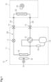
- an air conditioner 10 includes an outdoor unit 11, an indoor unit 21, and pipes 24 and 25.
- the outdoor unit 11 includes shutoff valves 12 and 13, a compressor 14, a four-way valve 15, an outdoor heat exchanger 16, an expansion valve 17, an accumulator 18, an axial fan 30, and a fan motor 19.
- the indoor unit 21 includes an indoor heat exchanger 22 and an indoor fan 23.
- the pipes 24 and 25 connect the outdoor unit 11 and the indoor unit 21.
- the pipes 24 and 25 are connected to the shutoff valves 12 and 13, respectively.
- the indoor unit 21 and the outdoor unit 11 are connected by the pipes 24 and 25 so that the air conditioner 10 includes a refrigerant circuit 26.
- the refrigerant circuit 26 is a circuit through which a refrigerant flows.
- the refrigerant circuit 26 includes the compressor 14, the four-way valve 15, the outdoor heat exchanger 16, the expansion valve 17, the accumulator 18, and the indoor heat exchanger 22.
- the four-way valve 15 is switched so that the refrigerant discharged from the compressor 14 is directed to the outdoor heat exchanger 16.
- the outdoor heat exchanger 16 transfers heat between the outdoor air and the refrigerant.
- the refrigerant, whose heat is dissipated in the outdoor heat exchanger 16, is depressurized by the expansion valve 17.
- the refrigerant depressurized by the expansion valve 17 flows into the indoor heat exchanger 22.
- the indoor heat exchanger 22 transfers heat between the indoor air and the refrigerant.
- the refrigerant that obtained heat from the indoor air in the indoor heat exchanger 22 is drawn back into the compressor 14 through the four-way valve 15 and the accumulator 18.
- the indoor air, whose heat is dissipated through the heat exchange in the indoor heat exchanger 22, cools the room.
- the axial fan 30 supplies the outdoor air to the outdoor heat exchanger 16.
- the indoor fan 23 supplies the indoor air to the indoor heat exchanger 22.
- the four-way valve 15 is switched so that the refrigerant discharged from the compressor 14 is directed to the indoor heat exchanger 22.
- the indoor heat exchanger 22 transfers heat between the indoor air and the refrigerant.
- the refrigerant that dissipated heat in the indoor heat exchanger 22 is depressurized by the expansion valve 17.
- the refrigerant depressurized by the expansion valve 17 flows into the outdoor heat exchanger 16.
- the outdoor heat exchanger 16 transfers heat between the outdoor air and the refrigerant.
- the refrigerant that obtained heat from the outdoor air in the outdoor heat exchanger 16 is drawn back into the compressor 14 through the four-way valve 15 and the accumulator 18.
- the indoor air that obtained heat through the heat exchange in the indoor heat exchanger 22 warms the room.
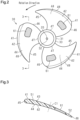
- the axial fan 30 includes a hub 31 and five or less blades 41.
- the hub 31 is cylindrical.
- the hub 31 is formed from, for example, resin.
- the hub 31 includes an insertion hole 32 and an outer circumferential surface 33.
- the insertion hole 32 is located at the center of the hub 31 in a radial direction.
- the insertion hole 32 receives a rotary shaft 20 of the fan motor 19. Rotation of the rotary shaft 20 rotates the axial fan 30.
- the rotary shaft 20 is rotated in a single direction.
- a rotation direction refers to a direction in which the rotary shaft 20 rotates.
- the number of blades 41 is three.
- the number of blades 41 may be five, four, or two.
- the blades 41 are arranged on the outer circumferential surface 33 of the hub 31.
- the blades 41 each extend from the outer circumferential surface 33 in the radial direction of the hub 31.
- the radial direction of the hub 31 is a direction orthogonal to the rotary shaft 20.
- the blades 41 are arranged at intervals in the rotation direction.
- the three blades 41 are identical in shape. In the description hereafter, a radial direction refers to the radial direction of the hub 31.
- the blade 41 includes a positive pressure surface 42 and a negative pressure surface 43.
- the positive pressure surface 42 is a blade surface located at a positive pressure side of an airflow generated by rotation of the axial fan 30.
- the negative pressure surface 43 is a blade surface located at a negative pressure side of an airflow generated by rotation of the axial fan 30.
- the positive pressure surface 42 is a surface from which air flows out when the axial fan 30 is rotated.
- the negative pressure surface 43 is a surface into which air flows when the axial fan 30 is rotated.
- the blades 41 each include a main body 44 and a porous part 61.
- the main body 44 is formed from, for example, resin.
- the hub 31 and the main body 44 are integrated with each other.
- the hub 31 and the main body 44 are integrally formed by, for example, injection molding.
- the main body 44 includes a leading edge 45, a trailing edge 46, an inner peripheral edge 47, and an outer peripheral edge 48.
- the leading edge 45 is an edge located forward in the rotation direction.
- the trailing edge 46 is an edge located rearward in the rotation direction.
- the leading edge 45 is curved.
- the leading edge 45 is curved in an arcuate manner so as to be recessed toward the trailing edge 46.
- the trailing edge 46 is curved.
- the trailing edge 46 is curved in an arcuate manner so as to extend away from the leading edge 45.
- the inner peripheral edge 47 is joined to the hub 31.
- the inner peripheral edge 47 extends between the leading edge 45 and the trailing edge 46.
- the outer peripheral edge 48 extends between the leading edge 45 and the trailing edge 46.
- a radial distance from the rotary shaft 20 to the inner peripheral edge 47 is less than a radial distance from the rotary shaft 20 to the outer peripheral edge 48.
- the outer peripheral edge 48 is curved.
- the outer peripheral edge 48 is curved in an arcuate manner so as to project in the radial direction.
- a dimension from the leading edge 45 to the trailing edge 46 will be referred to as a blade chord length L1. More specifically, the blade chord length L1 corresponds to a dimension of an imaginary line that connects multiple points located at the same radial distance from the rotary shaft 20 between the leading edge 45 and the trailing edge 46. In other words, the blade chord length L1 corresponds to a length of an arc extending between the leading edge 45 and the trailing edge 46 of the blade 41 when an imaginary circle is drawn about the rotary shaft 20.
- Fig. 4 shows three blade chord lengths L1 as an example. The blade chord length L1 may vary depending on its position on the blade 41 in the radial direction.
- a portion between a center position C1 of the blade chord length L1 and the leading edge 45 is defined as a leading edge portion 51
- a portion between the center position C1 of the blade chord length L1 and the trailing edge 46 is defined as a trailing edge portion 52.
- the leading edge portion 51 is heavier than the trailing edge portion 52.
- the main body 44 is gradually increased in thickness from the trailing edge 46 toward the leading edge 45 such that the leading edge portion 51 is heavier than the trailing edge portion 52.
- part of the leading edge portion 51 may be greater in thickness than the trailing edge portion 52 such that the leading edge portion 51 is heavier than the trailing edge portion 52.
- the porous part 61 is formed from a synthetic resin or ceramic.
- the porous part 61 has a lower strength than the main body 44.
- the porous part 61 is arranged in a region surrounded by the leading edge 45, the trailing edge 46, the inner peripheral edge 47, and the outer peripheral edge 48.
- the porous part 61 is entirely surrounded by the main body 44 that has a higher strength than the porous part 61.
- the porous part 61 includes pores extending between the positive pressure surface 42 and the negative pressure surface 43.
- the porous part 61 has an average pore diameter of, for example, 700 ⁇ m or less.
- the porous part 61 has a thickness of, for example, 5 mm or less.
- the porous part 61 is integrated with the main body 44.
- the porous part 61 and the main body 44 are integrated with each other by, for example, insert molding, adhesion, or fitting.
- the porous part 61 is quadrangular. More specifically, the porous part 61 has the form of a rounded quadrangle in which the four corners are curved.
- a distance from the leading edge 45 to the porous part 61 will be referred to as an arrangement distance L2. More specifically, the arrangement distance L2 corresponds to a dimension of an imaginary line that connects multiple points located at the same radial distance from the rotary shaft 20 between the leading edge 45 and the porous part 61. At the locations where the radial distance from the rotary shaft 20 is the same, "arrangement distance L2/blade chord length L1 ⁇ 40%" is satisfied. In other words, the porous part 61 is arranged at a position located rearward from the leading edge 45 by 40% or more of the blade chord length L1. Fig.
- a borderline L11 that lies along multiple points located rearward from the leading edge 45 by 40% of the blade chord length L1.
- a first region 53 is defined between the leading edge 45 and the borderline L11.
- a second region 54 is defined between the first region 53 and the trailing edge 46.
- the second region 54 includes the borderline L11.
- the porous part 61 is arranged only in the second region 54.
- the porous part 61 is not arranged in the first region 53. In other words, the porous part 61 is shifted toward the trailing edge 46.
- the portion of the porous part 61 included in the trailing edge portion 52 is larger than the portion of the porous part 61 included in the leading edge portion 51.
- the arrangement distance L2 and the blade chord length L1 both vary in accordance with the position from the rotary shaft 20 in the radial direction.
- the porous part 61 of the present embodiment is arranged such that "arrangement distance L2/blade chord length L1 ⁇ 40%" is satisfied regardless of the position from the rotary shaft 20 in the radial direction.
- the porous part 61 is arranged to reduce noise generated by the rotation of the axial fan 30.
- the noise reduction effect of the porous part 61 changes depending on the position where the porous part 61 is arranged.
- Fig. 5 indicates that a sound pressure level (dBA) of the noise generated by the axial fan 30 decreases as "arrangement distance L2/blade chord length L1 (%)" is increased.
- “arrangement distance L2/blade chord length L1" is set to 40% or more, the sound pressure level decreases significantly.
- a radial distance from the inner peripheral edge 47 to the outer peripheral edge 48 will be referred to as a first blade length R1.
- a radial distance from the inner peripheral edge 47 to a center position C2 of the porous part 61 will be referred to as a second blade length R2.
- the center position C2 of the porous part 61 is located at the center of the porous part 61 in the radial direction.
- the second blade length R2 and the first blade length R1 satisfy "second blade length R2/first blade length R1 > 50%".
- the porous part 61 is shifted from the center position, between the inner peripheral edge 47 and the outer peripheral edge 48, toward the outer peripheral edge 48.
- the main body 44 has a larger area than the porous part 61 on the positive pressure surface 42.
- the porous part 61 has an area that is 30% or less of the entire area of the positive pressure surface 42.
- the blade chord length L1 As the blade chord length L1 is increased, noise is more likely to be generated at the side of the blade 41 near the trailing edge 46.
- the blade chord length L1 may be increased in order to secure a desired workload. Accordingly, when the number of blades 41 is five or less, noise is likely to be generated at the side of each blade 41 near the trailing edge 46.
- a pressure fluctuation may cause generation of noise.
- the air moves between the side of the positive pressure surface 42 and the side of the negative pressure surface 43 through the porous part 61 so as to mitigate the pressure fluctuation.
- the porous part 61 located rearward from the leading edge 45 by 40% or more of the blade chord length L1 mitigates pressure fluctuations in the vicinity of the trailing edge 46 of the blade 41.
- Fig. 6 shows the sound generated by the rotation of the axial fan 30, the sound being broken down by frequency, and the sound pressure level corresponding to each frequency.
- Fig. 6 indicates that the axial fan 30 of the present embodiment reduces the sound pressure level compared to an axial fan without the porous part 61. In particular, the reduction in the sound pressure level is outstanding at a frequency at which the sound pressure level is relatively high.
- the first embodiment has the following advantages.
- the porous part 61 is located rearward from the leading edge 45 by 40% or more of the blade chord length L1.
- the porous part 61 may be reduced in size as compared to when the porous part 61 is arranged over the entire blade 41. This limits decreases in the strength of the blade 41.
- the porous part 61 Even when the porous part 61 is reduced in size, the porous part 61 arranged at a location where noise is likely to be generated reduces the noise generated by the rotation of the axial fan 30. Thus, the noise reduction effect of the porous part 61 can be obtained while limiting decreases in the strength of the blade 41.
- the porous part 61 is shifted toward the outer peripheral edge 48.
- the relative velocity of an airflow increases toward the outer peripheral edge 48. Further, an airflow having a higher relative velocity is more likely to generate noise. Thus, the porous part 61 shifted toward the outer peripheral edge 48 reduces noise.
- the area of the main body 44 is greater than the area of the porous part 61 on the positive pressure surface 42.
- the majority of the blade 41 is the main body 44 and the porous part 61 is included locally.
- the porous part 61 having a lower strength than the main body 44 is locally included, thereby limiting decreases in the strength of the blade 41.
- the area of the porous part 61 is set to 30% or less of the entire area of the positive pressure surface 42. This appropriately limits decreases in the strength of the blade 41.
- the leading edge portion 51 is heavier than the trailing edge portion 52 such that stress of the rotation of the axial fan 30 tends to concentrate in the leading edge portion 51. If the porous part 61 is arranged in the leading edge portion 51, where stress tends to concentrate, the strength of the leading edge portion 51 may become insufficient. When the porous part 61 is arranged within the second region 54, the porous part 61 is less likely to be located in the leading edge portion 51. Thus, the strength of the leading edge portion 51 will not be insufficient.
- the axial fan 30 is used in the air conditioner 10.
- the air conditioner 10 may have a large air capacity for better energy saving performances.
- the number of rotations of the axial fan 30 or the size of the axial fan 30 may be increased.
- the axial fan 30 needs to have a higher strength.
- the porous part 61 is reduced in size so as to increase the strength of the axial fan 30, noise may increase.
- the porous part 61 of the present embodiment arranged at a location where noise is likely to be generated reduces noise with a relatively small amount of porous part 61. This achieves compatibility between the strength of the axial fan 30 and the noise reduction effect.
- a trailing edge 71 of an axial fan 70 includes an inner peripheral connecting part 72, an outer peripheral connecting part 73, and a notch defining part 74.
- the inner peripheral connecting part 72 is connected to the inner peripheral edge 47.
- the inner peripheral connecting part 72 extends between the inner peripheral edge 47 and the notch defining part 74.
- the inner peripheral connecting part 72 is inclined rearward from the inner peripheral edge 47 toward the notch defining part 74.
- the outer peripheral connecting part 73 is connected to the outer peripheral edge 48.
- the outer peripheral connecting part 73 extends between the outer peripheral edge 48 and the notch defining part 74.
- the outer peripheral connecting part 73 is inclined rearward from the outer peripheral edge 48 toward the notch defining part 74.
- the notch defining part 74 is located between the inner peripheral connecting part 72 and the outer peripheral connecting part 73.
- the notch defining part 74 connects the inner peripheral connecting part 72 and the outer peripheral connecting part 73.
- the notch defining part 74 includes a first section 75, a second section 76, and a third section 77.
- the first section 75 is connected to the inner peripheral connecting part 72.
- the first section 75 extends from the inner peripheral connecting part 72 toward the leading edge 45.
- the first section 75 is inclined so as to approach the outer peripheral edge 48 as the first section 75 becomes farther away from the inner peripheral connecting part 72.
- the second section 76 is connected to the outer peripheral connecting part 73.
- the second section 76 extends from the outer peripheral connecting part 73 toward the leading edge 45.
- the second section 76 is inclined so as to approach the inner peripheral edge 47 as the second section 76 becomes farther away from the outer peripheral connecting part 73.
- the distance between the first section 75 and the second section 76 decreases as the first section 75 and the second section 76 approach the leading edge 45.
- the third section 77 connects the first section 75 and the second section 76.
- the third section 77 is curved so as to be recessed toward the leading edge 45.
- a notch 78 is formed in a region surrounded by the first section 75, the second section 76, and the third section 77.
- the notch defining part 74 defines the notch 78.
- the notch 78 is arranged to increase the air flow rate and reduce noise.
- the notch 78 extends between the positive pressure surface 42 and the negative pressure surface 43.
- the notch 78 is recessed toward the leading edge 45.
- an imaginary line extending in the rotation direction through a center position P1 of the third section 77 will be referred to as a trajectory L12.
- a length of the trajectory L12 from the leading edge 45 to the center position P1 of the third section 77 will be referred to as a first distance L3.
- the center position P1 of the third section 77 corresponds to a point of the notch defining part 74 located closest to the leading edge 45.
- a point at which the trajectory L12 intersects an imaginary line segment L13 connecting the first section 75 and the second section 76 will be referred to as an intersection P2.
- a length of the trajectory L12 from the leading edge 45 to the intersection P2 will be referred to as a second distance L4.
- the line segment L13 connects a point P3 of the first section 75 located closest to the inner peripheral edge 47 and a point P4 of the second section 76 located closest to the outer peripheral edge 48.
- the first distance L3 is 95% or less of the second distance.
- the notch 78 is recessed such that the center position P1 is located forward from the intersection P2 by 5% or more of the second distance L4.
- the blade 41 includes a non-arrangement range A1.
- the non-arrangement range A1 includes the trajectory L12 and is included in a range obtained by extending the notch 78 in the rotation direction.
- the non-arrangement range A1 of the present embodiment is a range obtained by extending, in the rotation direction, a circular range C3 centered on the center position P1 of the third section 77 and having a radius R4 that is 5 mm greater than a radius R3 of the third section 77.
- the non-arrangement range A1 extends from the trajectory L12 as a centerline toward both the inner peripheral edge 47 and the outer peripheral edge 48.
- the porous part 61 is located at a position outside the non-arrangement range A1. In the present embodiment, the porous part 61 is located between the non-arrangement range A1 and the inner peripheral edge 47. The porous part 61 may be located between the non-arrangement range A1 and the outer peripheral edge 48. The porous part 61 is arranged so as to not overlap the trajectory L12.
- the porous part 61 is separated from the center position P1 by a predetermined distance or more. Stress tends to concentrate in the notch defining part 74. In particular, stress tends to concentrate at the center position P1. Accordingly, the porous part 61 is separated from the center position P1 by a predetermined distance or more.
- the porous part 61 includes a cutout 62.
- the cutout 62 is formed at one of the four corners of the porous part 61 that is closest to the center position P1.
- the cutout 62 is a part where the corner is cut out.
- the cutout 62 is arranged such that the porous part 61 is located outside a predetermined distance from the center position P1.
- the cutout 62 is arranged to be parallel to the first section 75.
- the predetermined distance may be, for example, greater than the radius R4. However, there is no limit to such a configuration, and the predetermined distance may be changed in any manner.
- a third embodiment of the axial fan will now be described.
- the differences from the first embodiment will be described.
- the same reference names are given to those elements that are the same as the corresponding elements of the first embodiment, and such elements will not be described in detail.
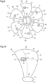
- an axial fan 80 includes six or more blades 81.
- the number of blades 81 shown in Fig. 9 is six.
- the number of blades 81 may be seven or more.
- the six blades 81 are identical in shape.
- Each of the blades 81 includes a main body 82 and a porous part 91.
- the main body 82 includes a leading edge 83, a trailing edge 84, an inner peripheral edge 85, and an outer peripheral edge 86.
- a first region 87 is defined between the leading edge 83 and the borderline L14.
- a second region 88 is defined between the first region 87 and the trailing edge 84.
- the porous part 91 is arranged only in the first region 87. In other words, the porous part 91 is shifted from a center position of the blade chord length L5 toward the leading edge 83.
- a center position between the inner peripheral edge 85 and the outer peripheral edge 86 may vary in accordance with its position in the rotation direction.
- the porous part 91 of the present embodiment is shifted from the center position, between the inner peripheral edge 85 and the outer peripheral edge 86, toward the outer peripheral edge 48 regardless of the position in the rotation direction.
- the blade chord length L5 As the blade chord length L5 is decreased, noise is more likely to be generated at the side of the blade 81 near the leading edge 83.
- the blade chord length L5 may be decreased in order to ensure formability of the axial fan 80 and secure flow paths between the blades 81. Accordingly, when the number of blades 81 is six or more, noise is likely to be generated at the side of each blade 81 near the leading edge 83.
- the porous part 91 is located forward from the trailing edge 84 by 60% or more of the blade chord length L5. This arranges the porous part 91 at a location where noise is likely to be generated. Consequently, noise is reduced at the side of the blade 81 near the leading edge 83.
- the third embodiment has the following advantages.
- the second embodiment has the following advantage.
- the porous part 91 is arranged at a location where noise is likely to be generated.
- the porous part 91 may be reduced in size as compared to when the porous part 91 is arranged over the entire blade 81. This limits decreases in the strength of the blade 81.
- the porous part 91 Even when the porous part 91 is reduced in size, the porous part 91 arranged at a location where noise is likely to be generated reduces the noise generated by the rotation of the axial fan 80. Thus, the noise reduction effect of the porous part 91 can be obtained while limiting decreases in the strength of the blade 81.
- the axial fan of the present disclosure is applicable to, for example, the following modifications and combinations of at least two of the modifications that do not contradict each other.
- the porous part 61 may be located forward from a position separated from the leading edge 45 by 40% of the blade chord length L1.
- the number of blades 41 may be six or more.
- the trailing edge 84 may include a notch defining part.
Landscapes
- Engineering & Computer Science (AREA)
- Mechanical Engineering (AREA)
- General Engineering & Computer Science (AREA)
- Chemical & Material Sciences (AREA)
- Combustion & Propulsion (AREA)
- Structures Of Non-Positive Displacement Pumps (AREA)
Abstract
Description
- The present disclosure relates to an axial fan.
- An axial fan includes a hub and blades arranged on the hub. The hub is attached to a rotary shaft. The blades and the hub rotate as the rotary shaft rotates. The rotation of the blades may cause pressure fluctuations, which generate noise. Patent Literature 1 discloses a blade that includes a porous portion. The porous portion reduces the pressure difference between the side of a positive pressure surface and the side of a negative pressure surface of the blade. This mitigates the pressure fluctuations, thereby reducing noise.
- Patent Literature 1:
Japanese Patent No. 2754862 - The porous portion arranged in the blade may decrease the strength of the blade.
- An axial fan that solves the above problem includes a hub and five or less blades. The hub is for attachment to a rotary shaft. The blades are arranged on the hub. The blades each include a leading edge located forward in a rotation direction of the rotary shaft, a trailing edge located rearward in the rotation direction of the rotary shaft, and a porous part. When a dimension from the leading edge to the trailing edge is referred to as a blade chord length, the porous part is arranged at a position located rearward from the leading edge by 40% or more of the blade chord length.
- When the number of blades is five or less, noise is likely to be generated at the trailing edge side of the blade. Thus, the porous part being located rearward from the leading edge by 40% or more of the blade chord length reduces the noise generated at the trailing edge side of the blade. When the porous part is arranged adjacent to a location where noise is generated, the porous part may be reduced in size as compared to when the porous part is arranged over the entire blade. This limits decreases in the strength of the blade.
- In the above axial fan, the blades may each include an inner peripheral edge joined to the hub, and an outer peripheral edge extending between the leading edge and the trailing edge in the rotation direction of the rotary shaft. The trailing edge may include an inner peripheral connecting part connected to the inner peripheral edge, an outer peripheral connecting part connected to the outer peripheral edge, a first section extending from the inner peripheral connecting part toward the leading edge, a second section extending from the outer peripheral connecting part toward the leading edge, and a third section curved and connecting the first section and the second section. When a length of a trajectory in the rotation direction from the leading edge to a center position of the third section is referred to as a first distance, and a length of the trajectory in the rotation direction from the leading edge to an intersection at which the trajectory intersects an imaginary line segment connecting the first section and the second section is referred to as a second distance, the first distance may be 95% or less of the second distance. When a range obtained by extending, in the rotation direction, a circular range centered on the center position of the third section and having a radius that is 5 mm greater than a radius of the third section is referred to as a non-arrangement range, the porous part may be located at a position outside the non-arrangement range.
- Stress tends to concentrate in the third section. Thus, if the distance between the third section and the porous part is excessively short, the strength of the blade may decrease. When the porous part is located outside the non-arrangement range obtained by extending, in the rotation direction, the circular range centered on the center position of the third section and having the radius that is 5 mm greater than the radius of the third section, decreases in the strength of the blade are limited as compared to when the porous part is located inside the non-arrangement range.
- In the above axial fan, the blades may each include an inner peripheral edge joined to the hub, and an outer peripheral edge extending between the leading edge and the trailing edge in the rotation direction of the rotary shaft. The porous part may be shifted from a center position, between the inner peripheral edge and the outer peripheral edge, toward the outer peripheral edge.
- The relative velocity of an airflow becomes higher toward the outer peripheral edge. Further, an airflow having a higher relative velocity is more likely to generate noise. Thus, the porous part shifted from the center position, between the inner peripheral edge and the outer peripheral edge, toward the outer peripheral edge reduces noise.
- In the above axial fan, the porous part may have an area that is 30% or less of an entire area of a positive pressure surface of a corresponding one of the blades.
- An axial fan that solves the above problem includes a hub and a blade. The hub is for attachment to a rotary shaft. The blade is arranged on the hub. The blade includes a leading edge located forward in a rotation direction of the rotary shaft, a trailing edge located rearward in the rotation direction of the rotary shaft, an inner peripheral edge joined to the hub, an outer peripheral edge extending between the leading edge and the trailing edge in the rotation direction of the rotary shaft, and a porous part. The trailing edge includes an inner peripheral connecting part connected to the inner peripheral edge, an outer peripheral connecting part connected to the outer peripheral edge, a first section extending from the inner peripheral connecting part toward the leading edge, a second section extending from the outer peripheral connecting part toward the leading edge, and a third section curved and connecting the first section and the second section. When a length of a trajectory in the rotation direction from the leading edge to a center position of the third section is referred to as a first distance, and a length of the trajectory in the rotation direction from the leading edge to an intersection at which the trajectory intersects an imaginary line segment connecting the first section and the second section is referred to as a second distance, the first distance is 95% or less of the second distance. When a range obtained by extending, in the rotation direction, a circular range centered on the center position of the third section and having a radius that is 5 mm greater than a radius of the third section is referred to as a non-arrangement range, the porous part is located at a position outside the non-arrangement range.
- Stress tends to concentrate in the third section. Thus, if the distance between the third section and the porous part is excessively short, the strength of the blade may decrease. When the porous part is arranged at a position outside the non-arrangement range, decreases in the strength of the blade are limited as compared to when the porous part is arranged inside the non-arrangement range.
- An axial fan that solves the above problem includes a hub and six or more blades. The hub is for attachment to a rotary shaft. The blades are arranged on the hub. The blades each include a leading edge located forward in a rotation direction of the rotary shaft, a trailing edge located rearward in the rotation direction of the rotary shaft, and a porous part. When a dimension from the leading edge to the trailing edge is referred to as a blade chord length, the porous part is arranged at a position located forward from the trailing edge by 60% or more of the blade chord length.
- When the number of blades is six or more, noise is likely to be generated at the leading edge side of the blade. Thus, the porous part arranged at a position located forward from the trailing edge by 60% or more of the blade chord length reduces the noise generated at the leading edge side of the blade. When the porous part is arranged adjacent to a location where noise is generated, the porous part may be reduced in size as compared to when the porous part is arranged over the entire blade. This limits decreases in the strength of the blade.
-
-
Fig. 1 is a schematic diagram showing the configuration of an air conditioner. -
Fig. 2 is a front view of an axial fan in accordance with a first embodiment as viewed from the side of a positive pressure surface. -
Fig. 3 is a cross-sectional view of a blade in accordance with the first embodiment taken along line 3-3 shown inFig. 2 . -
Fig. 4 is an enlarged view of the blade in accordance with the first embodiment. -
Fig. 5 is a diagram showing the relationship between a sound pressure level of noise generated by rotation of the axial fan and the position of a porous part. -
Fig. 6 is a diagram showing the sound pressure level of each frequency in an axial fan without the porous part and the axial fan in accordance with the first embodiment. -
Fig. 7 is a front view of an axial fan in accordance with a second embodiment as viewed from the side of a positive pressure surface. -
Fig. 8 is an enlarged view of a blade in accordance with the second embodiment. -
Fig. 9 is a front view of an axial fan in accordance with a third embodiment as viewed from the side of a positive pressure surface. -
Fig. 10 is an enlarged view of a blade in accordance with the third embodiment. - A first embodiment of an axial fan will now be described.
- As shown in
Fig. 1 , anair conditioner 10 includes anoutdoor unit 11, anindoor unit 21, andpipes outdoor unit 11 includesshutoff valves compressor 14, a four-way valve 15, anoutdoor heat exchanger 16, anexpansion valve 17, an accumulator 18, anaxial fan 30, and afan motor 19. Theindoor unit 21 includes anindoor heat exchanger 22 and anindoor fan 23. - The
pipes outdoor unit 11 and theindoor unit 21. Thepipes shutoff valves indoor unit 21 and theoutdoor unit 11 are connected by thepipes air conditioner 10 includes arefrigerant circuit 26. Therefrigerant circuit 26 is a circuit through which a refrigerant flows. Therefrigerant circuit 26 includes thecompressor 14, the four-way valve 15, theoutdoor heat exchanger 16, theexpansion valve 17, the accumulator 18, and theindoor heat exchanger 22. - During a cooling operation of the
air conditioner 10, the four-way valve 15 is switched so that the refrigerant discharged from thecompressor 14 is directed to theoutdoor heat exchanger 16. Theoutdoor heat exchanger 16 transfers heat between the outdoor air and the refrigerant. The refrigerant, whose heat is dissipated in theoutdoor heat exchanger 16, is depressurized by theexpansion valve 17. The refrigerant depressurized by theexpansion valve 17 flows into theindoor heat exchanger 22. Theindoor heat exchanger 22 transfers heat between the indoor air and the refrigerant. The refrigerant that obtained heat from the indoor air in theindoor heat exchanger 22 is drawn back into thecompressor 14 through the four-way valve 15 and the accumulator 18. The indoor air, whose heat is dissipated through the heat exchange in theindoor heat exchanger 22, cools the room. Theaxial fan 30 supplies the outdoor air to theoutdoor heat exchanger 16. Theindoor fan 23 supplies the indoor air to theindoor heat exchanger 22. - During a heating operation of the
air conditioner 10, the four-way valve 15 is switched so that the refrigerant discharged from thecompressor 14 is directed to theindoor heat exchanger 22. Theindoor heat exchanger 22 transfers heat between the indoor air and the refrigerant. The refrigerant that dissipated heat in theindoor heat exchanger 22 is depressurized by theexpansion valve 17. The refrigerant depressurized by theexpansion valve 17 flows into theoutdoor heat exchanger 16. Theoutdoor heat exchanger 16 transfers heat between the outdoor air and the refrigerant. The refrigerant that obtained heat from the outdoor air in theoutdoor heat exchanger 16 is drawn back into thecompressor 14 through the four-way valve 15 and the accumulator 18. The indoor air that obtained heat through the heat exchange in theindoor heat exchanger 22 warms the room. - As shown in
Fig. 2 , theaxial fan 30 includes ahub 31 and five orless blades 41. - The
hub 31 is cylindrical. Thehub 31 is formed from, for example, resin. Thehub 31 includes aninsertion hole 32 and an outercircumferential surface 33. Theinsertion hole 32 is located at the center of thehub 31 in a radial direction. Theinsertion hole 32 receives arotary shaft 20 of thefan motor 19. Rotation of therotary shaft 20 rotates theaxial fan 30. Therotary shaft 20 is rotated in a single direction. In the description hereafter, a rotation direction refers to a direction in which therotary shaft 20 rotates. - The number of
blades 41 is three. The number ofblades 41 may be five, four, or two. Theblades 41 are arranged on the outercircumferential surface 33 of thehub 31. Theblades 41 each extend from the outercircumferential surface 33 in the radial direction of thehub 31. The radial direction of thehub 31 is a direction orthogonal to therotary shaft 20. Theblades 41 are arranged at intervals in the rotation direction. The threeblades 41 are identical in shape. In the description hereafter, a radial direction refers to the radial direction of thehub 31. - As shown in
Fig. 3 , theblade 41 includes apositive pressure surface 42 and anegative pressure surface 43. Thepositive pressure surface 42 is a blade surface located at a positive pressure side of an airflow generated by rotation of theaxial fan 30. Thenegative pressure surface 43 is a blade surface located at a negative pressure side of an airflow generated by rotation of theaxial fan 30. Thepositive pressure surface 42 is a surface from which air flows out when theaxial fan 30 is rotated. Thenegative pressure surface 43 is a surface into which air flows when theaxial fan 30 is rotated. - As shown in
Fig. 2 , theblades 41 each include amain body 44 and aporous part 61. Themain body 44 is formed from, for example, resin. Thehub 31 and themain body 44 are integrated with each other. Thehub 31 and themain body 44 are integrally formed by, for example, injection molding. - The
main body 44 includes aleading edge 45, a trailingedge 46, an innerperipheral edge 47, and an outerperipheral edge 48. The leadingedge 45 is an edge located forward in the rotation direction. The trailingedge 46 is an edge located rearward in the rotation direction. The leadingedge 45 is curved. The leadingedge 45 is curved in an arcuate manner so as to be recessed toward the trailingedge 46. The trailingedge 46 is curved. The trailingedge 46 is curved in an arcuate manner so as to extend away from the leadingedge 45. The innerperipheral edge 47 is joined to thehub 31. The innerperipheral edge 47 extends between theleading edge 45 and the trailingedge 46. The outerperipheral edge 48 extends between theleading edge 45 and the trailingedge 46. A radial distance from therotary shaft 20 to the innerperipheral edge 47 is less than a radial distance from therotary shaft 20 to the outerperipheral edge 48. The outerperipheral edge 48 is curved. The outerperipheral edge 48 is curved in an arcuate manner so as to project in the radial direction. - As shown in
Fig. 4 , a dimension from the leadingedge 45 to the trailingedge 46 will be referred to as a blade chord length L1. More specifically, the blade chord length L1 corresponds to a dimension of an imaginary line that connects multiple points located at the same radial distance from therotary shaft 20 between theleading edge 45 and the trailingedge 46. In other words, the blade chord length L1 corresponds to a length of an arc extending between theleading edge 45 and the trailingedge 46 of theblade 41 when an imaginary circle is drawn about therotary shaft 20.Fig. 4 shows three blade chord lengths L1 as an example. The blade chord length L1 may vary depending on its position on theblade 41 in the radial direction. - As shown in
Fig. 3 , a portion between a center position C1 of the blade chord length L1 and the leadingedge 45 is defined as aleading edge portion 51, and a portion between the center position C1 of the blade chord length L1 and the trailingedge 46 is defined as a trailingedge portion 52. Theleading edge portion 51 is heavier than the trailingedge portion 52. For example, as shown inFig. 3 , themain body 44 is gradually increased in thickness from the trailingedge 46 toward the leadingedge 45 such that theleading edge portion 51 is heavier than the trailingedge portion 52. Alternatively, part of theleading edge portion 51 may be greater in thickness than the trailingedge portion 52 such that theleading edge portion 51 is heavier than the trailingedge portion 52. - The
porous part 61 is formed from a synthetic resin or ceramic. Theporous part 61 has a lower strength than themain body 44. Theporous part 61 is arranged in a region surrounded by the leadingedge 45, the trailingedge 46, the innerperipheral edge 47, and the outerperipheral edge 48. Theporous part 61 is entirely surrounded by themain body 44 that has a higher strength than theporous part 61. Theporous part 61 includes pores extending between thepositive pressure surface 42 and thenegative pressure surface 43. Theporous part 61 has an average pore diameter of, for example, 700 µm or less. Theporous part 61 has a thickness of, for example, 5 mm or less. Theporous part 61 is integrated with themain body 44. Theporous part 61 and themain body 44 are integrated with each other by, for example, insert molding, adhesion, or fitting. - The
porous part 61 is quadrangular. More specifically, theporous part 61 has the form of a rounded quadrangle in which the four corners are curved. - As shown in
Fig. 4 , a distance from the leadingedge 45 to theporous part 61 will be referred to as an arrangement distance L2. More specifically, the arrangement distance L2 corresponds to a dimension of an imaginary line that connects multiple points located at the same radial distance from therotary shaft 20 between theleading edge 45 and theporous part 61. At the locations where the radial distance from therotary shaft 20 is the same, "arrangement distance L2/blade chord length L1 ≥ 40%" is satisfied. In other words, theporous part 61 is arranged at a position located rearward from the leadingedge 45 by 40% or more of the blade chord length L1.Fig. 4 shows a borderline L11 that lies along multiple points located rearward from the leadingedge 45 by 40% of the blade chord length L1. Afirst region 53 is defined between theleading edge 45 and the borderline L11. Asecond region 54 is defined between thefirst region 53 and the trailingedge 46. Thesecond region 54 includes the borderline L11. Theporous part 61 is arranged only in thesecond region 54. Theporous part 61 is not arranged in thefirst region 53. In other words, theporous part 61 is shifted toward the trailingedge 46. The portion of theporous part 61 included in the trailingedge portion 52 is larger than the portion of theporous part 61 included in theleading edge portion 51. - In the present embodiment, the arrangement distance L2 and the blade chord length L1 both vary in accordance with the position from the
rotary shaft 20 in the radial direction. In this case, theporous part 61 of the present embodiment is arranged such that "arrangement distance L2/blade chord length L1 ≥ 40%" is satisfied regardless of the position from therotary shaft 20 in the radial direction. - The
porous part 61 is arranged to reduce noise generated by the rotation of theaxial fan 30. The noise reduction effect of theporous part 61 changes depending on the position where theporous part 61 is arranged. -
Fig. 5 indicates that a sound pressure level (dBA) of the noise generated by theaxial fan 30 decreases as "arrangement distance L2/blade chord length L1 (%)" is increased. In particular, when "arrangement distance L2/blade chord length L1" is set to 40% or more, the sound pressure level decreases significantly. - As shown in
Fig. 4 , a radial distance from the innerperipheral edge 47 to the outerperipheral edge 48 will be referred to as a first blade length R1. A radial distance from the innerperipheral edge 47 to a center position C2 of theporous part 61 will be referred to as a second blade length R2. The center position C2 of theporous part 61 is located at the center of theporous part 61 in the radial direction. The second blade length R2 and the first blade length R1 satisfy "second blade length R2/first blade length R1 > 50%". Theporous part 61 is shifted from the center position, between the innerperipheral edge 47 and the outerperipheral edge 48, toward the outerperipheral edge 48. Theblade 41 may be divided into an innerperipheral region 55 and an outerperipheral region 56 by a boundary that extends along the center position of theblade 41 in the radial direction. The innerperipheral region 55 is located closer to thehub 31 than the outerperipheral region 56 is to thehub 31. In this case, portion of theporous part 61 included in the outerperipheral region 56 is larger than portion of theporous part 61 included in the innerperipheral region 55. - The
main body 44 has a larger area than theporous part 61 on thepositive pressure surface 42. In the present embodiment, theporous part 61 has an area that is 30% or less of the entire area of thepositive pressure surface 42. - As the blade chord length L1 is increased, noise is more likely to be generated at the side of the
blade 41 near the trailingedge 46. When the number ofblades 41 is five or less, the blade chord length L1 may be increased in order to secure a desired workload. Accordingly, when the number ofblades 41 is five or less, noise is likely to be generated at the side of eachblade 41 near the trailingedge 46. A pressure fluctuation may cause generation of noise. When a pressure fluctuation occurs, the air moves between the side of thepositive pressure surface 42 and the side of thenegative pressure surface 43 through theporous part 61 so as to mitigate the pressure fluctuation. In particular, theporous part 61 located rearward from the leadingedge 45 by 40% or more of the blade chord length L1 mitigates pressure fluctuations in the vicinity of the trailingedge 46 of theblade 41. -
Fig. 6 shows the sound generated by the rotation of theaxial fan 30, the sound being broken down by frequency, and the sound pressure level corresponding to each frequency.Fig. 6 indicates that theaxial fan 30 of the present embodiment reduces the sound pressure level compared to an axial fan without theporous part 61. In particular, the reduction in the sound pressure level is outstanding at a frequency at which the sound pressure level is relatively high. - The first embodiment has the following advantages.
- (1-1) The
porous part 61 is located rearward from the leadingedge 45 by 40% or more of the blade chord length L1. When theporous part 61 is arranged at a location where noise is likely to be generated, theporous part 61 may be reduced in size as compared to when theporous part 61 is arranged over theentire blade 41. This limits decreases in the strength of theblade 41. - Even when the
porous part 61 is reduced in size, theporous part 61 arranged at a location where noise is likely to be generated reduces the noise generated by the rotation of theaxial fan 30. Thus, the noise reduction effect of theporous part 61 can be obtained while limiting decreases in the strength of theblade 41. - (1-2) The
porous part 61 is shifted toward the outerperipheral edge 48. The relative velocity of an airflow increases toward the outerperipheral edge 48. Further, an airflow having a higher relative velocity is more likely to generate noise. Thus, theporous part 61 shifted toward the outerperipheral edge 48 reduces noise. - (1-3) The area of the
main body 44 is greater than the area of theporous part 61 on thepositive pressure surface 42. The majority of theblade 41 is themain body 44 and theporous part 61 is included locally. Theporous part 61 having a lower strength than themain body 44 is locally included, thereby limiting decreases in the strength of theblade 41. In particular, the area of theporous part 61 is set to 30% or less of the entire area of thepositive pressure surface 42. This appropriately limits decreases in the strength of theblade 41. - (1-4) The
leading edge portion 51 is heavier than the trailingedge portion 52 such that stress of the rotation of theaxial fan 30 tends to concentrate in theleading edge portion 51. If theporous part 61 is arranged in theleading edge portion 51, where stress tends to concentrate, the strength of theleading edge portion 51 may become insufficient. When theporous part 61 is arranged within thesecond region 54, theporous part 61 is less likely to be located in theleading edge portion 51. Thus, the strength of theleading edge portion 51 will not be insufficient. - (1-5) The
axial fan 30 is used in theair conditioner 10. Theair conditioner 10 may have a large air capacity for better energy saving performances. In order to obtain a larger air capacity, the number of rotations of theaxial fan 30 or the size of theaxial fan 30 may be increased. In this case, theaxial fan 30 needs to have a higher strength. Nonetheless, if theporous part 61 is reduced in size so as to increase the strength of theaxial fan 30, noise may increase. In this respect, theporous part 61 of the present embodiment arranged at a location where noise is likely to be generated reduces noise with a relatively small amount ofporous part 61. This achieves compatibility between the strength of theaxial fan 30 and the noise reduction effect. - A second embodiment of the axial fan will now be described. In the second embodiment, the differences from the first embodiment will be described. The same reference names are given to those elements that are the same as the corresponding elements of the first embodiment, and such elements will not be described in detail.
- As shown in
Fig. 7 , a trailingedge 71 of anaxial fan 70 includes an inner peripheral connectingpart 72, an outer peripheral connectingpart 73, and anotch defining part 74. - The inner peripheral connecting
part 72 is connected to the innerperipheral edge 47. The inner peripheral connectingpart 72 extends between the innerperipheral edge 47 and thenotch defining part 74. The inner peripheral connectingpart 72 is inclined rearward from the innerperipheral edge 47 toward thenotch defining part 74. - The outer peripheral connecting
part 73 is connected to the outerperipheral edge 48. The outer peripheral connectingpart 73 extends between the outerperipheral edge 48 and thenotch defining part 74. The outer peripheral connectingpart 73 is inclined rearward from the outerperipheral edge 48 toward thenotch defining part 74. - The
notch defining part 74 is located between the inner peripheral connectingpart 72 and the outer peripheral connectingpart 73. Thenotch defining part 74 connects the inner peripheral connectingpart 72 and the outer peripheral connectingpart 73. Thenotch defining part 74 includes afirst section 75, asecond section 76, and athird section 77. - The
first section 75 is connected to the inner peripheral connectingpart 72. Thefirst section 75 extends from the inner peripheral connectingpart 72 toward the leadingedge 45. Thefirst section 75 is inclined so as to approach the outerperipheral edge 48 as thefirst section 75 becomes farther away from the inner peripheral connectingpart 72. - The
second section 76 is connected to the outer peripheral connectingpart 73. Thesecond section 76 extends from the outer peripheral connectingpart 73 toward the leadingedge 45. Thesecond section 76 is inclined so as to approach the innerperipheral edge 47 as thesecond section 76 becomes farther away from the outer peripheral connectingpart 73. The distance between thefirst section 75 and thesecond section 76 decreases as thefirst section 75 and thesecond section 76 approach the leadingedge 45. - The
third section 77 connects thefirst section 75 and thesecond section 76. Thethird section 77 is curved so as to be recessed toward the leadingedge 45. Anotch 78 is formed in a region surrounded by thefirst section 75, thesecond section 76, and thethird section 77. Thenotch defining part 74 defines thenotch 78. Thenotch 78 is arranged to increase the air flow rate and reduce noise. Thenotch 78 extends between thepositive pressure surface 42 and thenegative pressure surface 43. Thenotch 78 is recessed toward the leadingedge 45. - As shown in
Fig. 8 , an imaginary line extending in the rotation direction through a center position P1 of thethird section 77 will be referred to as a trajectory L12. A length of the trajectory L12 from the leadingedge 45 to the center position P1 of thethird section 77 will be referred to as a first distance L3. The center position P1 of thethird section 77 corresponds to a point of thenotch defining part 74 located closest to the leadingedge 45. - A point at which the trajectory L12 intersects an imaginary line segment L13 connecting the
first section 75 and thesecond section 76 will be referred to as an intersection P2. A length of the trajectory L12 from the leadingedge 45 to the intersection P2 will be referred to as a second distance L4. The line segment L13 connects a point P3 of thefirst section 75 located closest to the innerperipheral edge 47 and a point P4 of thesecond section 76 located closest to the outerperipheral edge 48. The first distance L3 is 95% or less of the second distance. In other words, thenotch 78 is recessed such that the center position P1 is located forward from the intersection P2 by 5% or more of the second distance L4. - The
blade 41 includes a non-arrangement range A1. The non-arrangement range A1 includes the trajectory L12 and is included in a range obtained by extending thenotch 78 in the rotation direction. The non-arrangement range A1 of the present embodiment is a range obtained by extending, in the rotation direction, a circular range C3 centered on the center position P1 of thethird section 77 and having a radius R4 that is 5 mm greater than a radius R3 of thethird section 77. The non-arrangement range A1 extends from the trajectory L12 as a centerline toward both the innerperipheral edge 47 and the outerperipheral edge 48. - The
porous part 61 is located at a position outside the non-arrangement range A1. In the present embodiment, theporous part 61 is located between the non-arrangement range A1 and the innerperipheral edge 47. Theporous part 61 may be located between the non-arrangement range A1 and the outerperipheral edge 48. Theporous part 61 is arranged so as to not overlap the trajectory L12. - The
porous part 61 is separated from the center position P1 by a predetermined distance or more. Stress tends to concentrate in thenotch defining part 74. In particular, stress tends to concentrate at the center position P1. Accordingly, theporous part 61 is separated from the center position P1 by a predetermined distance or more. In the present embodiment, theporous part 61 includes acutout 62. Thecutout 62 is formed at one of the four corners of theporous part 61 that is closest to the center position P1. Thecutout 62 is a part where the corner is cut out. Thecutout 62 is arranged such that theporous part 61 is located outside a predetermined distance from the center position P1. This allows theporous part 61 to be adjacent to the trailingedge 71 without becoming excessively close to the center position P1. Thecutout 62 is arranged to be parallel to thefirst section 75. The predetermined distance may be, for example, greater than the radius R4. However, there is no limit to such a configuration, and the predetermined distance may be changed in any manner. - The second embodiment has the following advantages in addition to the advantages of the first embodiment.
- (2-1) Stress tends to concentrate in the
third section 77. Thus, if the distance between thethird section 77 and theporous part 61 is excessively short, the strength of theblade 41 may decrease. When theporous part 61 is arranged at a position outside the non-arrangement range A1, decreases in the strength of theblade 41 are limited as compared to when theporous part 61 is arranged inside the non-arrangement range A1. - A third embodiment of the axial fan will now be described. In the third embodiment, the differences from the first embodiment will be described. The same reference names are given to those elements that are the same as the corresponding elements of the first embodiment, and such elements will not be described in detail.
- As shown in
Fig. 9 , anaxial fan 80 includes six ormore blades 81. The number ofblades 81 shown inFig. 9 is six. The number ofblades 81 may be seven or more. The sixblades 81 are identical in shape. - Each of the
blades 81 includes amain body 82 and aporous part 91. Themain body 82 includes aleading edge 83, a trailingedge 84, an innerperipheral edge 85, and an outerperipheral edge 86. - As shown in
Fig. 10 , a dimension from the leadingedge 83 to the trailingedge 84 will be referred to as a blade chord length L5. A distance from the trailingedge 84 to theporous part 91 will be referred to as an arrangement distance L6. At locations where the radial distance from therotary shaft 20 is the same, "arrangement distance L6/blade chord length L5 ≥ 60%" is satisfied. In other words, theporous part 91 is arranged at a position located forward from the trailingedge 84 by 60% or more of the blade chord length L5.Fig. 10 shows an imaginary borderline L14 that connects multiple points separated from the trailingedge 84 by 60% of the blade chord length L5. Afirst region 87 is defined between theleading edge 83 and the borderline L14. Asecond region 88 is defined between thefirst region 87 and the trailingedge 84. Theporous part 91 is arranged only in thefirst region 87. In other words, theporous part 91 is shifted from a center position of the blade chord length L5 toward the leadingedge 83. - In the present embodiment, a center position between the inner
peripheral edge 85 and the outerperipheral edge 86 may vary in accordance with its position in the rotation direction. Theporous part 91 of the present embodiment is shifted from the center position, between the innerperipheral edge 85 and the outerperipheral edge 86, toward the outerperipheral edge 48 regardless of the position in the rotation direction. - As the blade chord length L5 is decreased, noise is more likely to be generated at the side of the
blade 81 near the leadingedge 83. When the number ofblades 81 is six or more, the blade chord length L5 may be decreased in order to ensure formability of theaxial fan 80 and secure flow paths between theblades 81. Accordingly, when the number ofblades 81 is six or more, noise is likely to be generated at the side of eachblade 81 near the leadingedge 83. Theporous part 91 is located forward from the trailingedge 84 by 60% or more of the blade chord length L5. This arranges theporous part 91 at a location where noise is likely to be generated. Consequently, noise is reduced at the side of theblade 81 near the leadingedge 83. - The third embodiment has the following advantages. In addition to the advantages (1-2), (1-3), and (1-5) of the first embodiment, the second embodiment has the following advantage.
- (3-1) The
porous part 91 is arranged at a location where noise is likely to be generated. Thus, theporous part 91 may be reduced in size as compared to when theporous part 91 is arranged over theentire blade 81. This limits decreases in the strength of theblade 81. - Even when the
porous part 91 is reduced in size, theporous part 91 arranged at a location where noise is likely to be generated reduces the noise generated by the rotation of theaxial fan 80. Thus, the noise reduction effect of theporous part 91 can be obtained while limiting decreases in the strength of theblade 81. - In addition to the above embodiments, the axial fan of the present disclosure is applicable to, for example, the following modifications and combinations of at least two of the modifications that do not contradict each other.
- In the second embodiment, the
porous part 61 may be located forward from a position separated from the leadingedge 45 by 40% of the blade chord length L1. - In the second embodiment, the number of
blades 41 may be six or more. - In the third embodiment, the trailing
edge 84 may include a notch defining part. - It should be understood that the above-described disclosure may be embodied in many other specific forms within the scope and equivalence of the axial fan described in the appended claims.
- Technical concepts obtained from the above embodiments and the modified examples will now be described.
- (1) An axial fan including a hub and a blade. The hub is for attachment to a rotary shaft. The blade is arranged on the hub. The blade includes a leading edge, a trailing edge, an inner peripheral edge, an outer peripheral edge, and a porous part. The leading edge is located forward in a rotation direction of the rotary shaft. The trailing edge is located rearward in the rotation direction of the rotary shaft. The inner peripheral edge is joined to the hub. The outer peripheral edge extends between the leading edge and the trailing edge in the rotation direction of the rotary shaft. The leading edge includes a notch defining part that forms a notch recessed toward the leading edge. The porous part is arranged so as to not overlap a trajectory that extends in the rotation direction through a point of the notch defining part located closest to the leading edge.
- (2) An axial fan including a hub and six or more blades. The hub is for attachment to a rotary shaft. The blades are arranged on the hub. The blades each include a leading edge, a trailing edge, and a porous part. The leading edge is located forward in a rotation direction of the rotary shaft. The trailing edge is located rearward in the rotation direction of the rotary shaft. When a dimension from the leading edge to the trailing edge is referred to as a blade chord length, the porous part is shifted from a center position of the blade chord length toward the leading edge.
Claims (6)
- An axial fan, comprising:a hub (31) for attachment to a rotary shaft (20); andfive or less blades (41) arranged on the hub (31), wherein:the blades (41) each includea leading edge (45) located forward in a rotation direction of the rotary shaft (20),a trailing edge (46, 71) located rearward in the rotation direction of the rotary shaft (20), anda porous part (61); andwhen a dimension from the leading edge (45) to the trailing edge (46, 71) is referred to as a blade chord length (L1), the porous part (61) is arranged at a position located rearward from the leading edge (45) by 40% or more of the blade chord length (L1).
- The axial fan according to claim 1, wherein:the blades (41) each includean inner peripheral edge (47) joined to the hub (31), andan outer peripheral edge (48) extending between the leading edge (45) and the trailing edge (71) in the rotation direction of the rotary shaft (20);the trailing edge (71) includesan inner peripheral connecting part (72) connected to the inner peripheral edge (47),an outer peripheral connecting part (73) connected to the outer peripheral edge (48),a first section (75) extending from the inner peripheral connecting part (72) toward the leading edge (45),a second section (76) extending from the outer peripheral connecting part (73) toward the leading edge (45), anda third section (77) curved and connecting the first section (75) and the second section (76);when a length of a trajectory (L12) in the rotation direction from the leading edge (45) to a center position (P1) of the third section (77) is referred to as a first distance (L3), and a length of the trajectory (L12) in the rotation direction from the leading edge (45) to an intersection (P2) at which the trajectory (L12) intersects an imaginary line segment (L13) connecting the first section (75) and the second section (76) is referred to as a second distance (L4), the first distance (L3) is 95% or less of the second distance (L4); andwhen a range obtained by extending, in the rotation direction, a circular range (C3) centered on the center position (P1) of the third section (77) and having a radius (R4) that is 5 mm greater than a radius (R3) of the third section (77) is referred to as a non-arrangement range (A1), the porous part (61) is located at a position outside the non-arrangement range (A1).
- The axial fan according to claim 1 or 2, wherein:the blades (41) each includean inner peripheral edge (47) joined to the hub (31), andan outer peripheral edge (48) extending between the leading edge (45) and the trailing edge (46, 71) in the rotation direction of the rotary shaft (20); andthe porous part (61) is shifted from a center position, between the inner peripheral edge (47) and the outer peripheral edge (48), toward the outer peripheral edge (48).
- The axial fan according to any one of claims 1 to 3, wherein the porous part (61) has an area that is 30% or less of an entire area of a positive pressure surface of a corresponding one of the blades (41).
- An axial fan, comprising:a hub (31) for attachment to a rotary shaft (20); anda blade (41) arranged on the hub (31), wherein:the blade (41) includesa leading edge (45) located forward in a rotation direction of the rotary shaft (20),a trailing edge (71) located rearward in the rotation direction of the rotary shaft (20),an inner peripheral edge (47) joined to the hub (31),an outer peripheral edge (48) extending between the leading edge (45) and the trailing edge (71) in the rotation direction of the rotary shaft (20), anda porous part (61); andthe trailing edge (71) includesan inner peripheral connecting part (72) connected to the inner peripheral edge (47),an outer peripheral connecting part (73) connected to the outer peripheral edge (48),a first section (75) extending from the inner peripheral connecting part (72) toward the leading edge (45),a second section (76) extending from the outer peripheral connecting part (73) toward the leading edge (45), anda third section (77) curved and connecting the first section (75) and the second section (76);when a length of a trajectory (L12) in the rotation direction from the leading edge (45) to a center position (P1) of the third section (77) is referred to as a first distance (L3), and a length of the trajectory (L12) in the rotation direction from the leading edge (45) to an intersection (P2) at which the trajectory (L12) intersects an imaginary line segment (L13) connecting the first section (75) and the second section (76) is referred to as a second distance (L4), the first distance (L3) is 95% or less of the second distance (L4); andwhen a range obtained by extending, in the rotation direction, a circular range (C3) centered on the center position (P1) of the third section (77) and having a radius (R4) that is 5 mm greater than a radius (R3) of the third section (77) is referred to as a non-arrangement range (A1), the porous part (61) is located at a position outside the non-arrangement range (A1).
- An axial fan, comprising:a hub (31) for attachment to a rotary shaft (20); andsix or more blades (81) arranged on the hub (31), wherein:the blades (81) each includea leading edge (83) located forward in a rotation direction of the rotary shaft (20),a trailing edge (84) located rearward in the rotation direction of the rotary shaft (20), anda porous part (91); andwhen a dimension from the leading edge (83) to the trailing edge (84) is referred to as a blade chord length (L5), the porous part (91) is arranged at a position located forward from the trailing edge (84) by 60% or more of the blade chord length (L5).
Applications Claiming Priority (2)
| Application Number | Priority Date | Filing Date | Title |
|---|---|---|---|
| JP2022060652A JP7393682B2 (en) | 2022-03-31 | 2022-03-31 | axial fan |
| PCT/JP2023/009786 WO2023189522A1 (en) | 2022-03-31 | 2023-03-14 | Axial fan |
Publications (2)
| Publication Number | Publication Date |
|---|---|
| EP4502391A1 true EP4502391A1 (en) | 2025-02-05 |
| EP4502391A4 EP4502391A4 (en) | 2025-11-05 |
Family
ID=88200963
Family Applications (1)
| Application Number | Title | Priority Date | Filing Date |
|---|---|---|---|
| EP23779542.2A Pending EP4502391A4 (en) | 2022-03-31 | 2023-03-14 | AXIAL FAN |
Country Status (5)
| Country | Link |
|---|---|
| US (1) | US20250243880A1 (en) |
| EP (1) | EP4502391A4 (en) |
| JP (1) | JP7393682B2 (en) |
| CN (1) | CN118922634B (en) |
| WO (1) | WO2023189522A1 (en) |
Families Citing this family (2)
| Publication number | Priority date | Publication date | Assignee | Title |
|---|---|---|---|---|
| JP7832524B1 (en) | 2024-09-03 | 2026-03-18 | ダイキン工業株式会社 | Fans and air conditioning systems |
| CN120798874B (en) * | 2025-09-09 | 2025-11-21 | 中国航发商用航空发动机有限责任公司 | Pneumatic layout structure of open rotor blade, open rotor and engine thereof |
Family Cites Families (17)
| Publication number | Priority date | Publication date | Assignee | Title |
|---|---|---|---|---|
| JPS6245395U (en) * | 1985-09-06 | 1987-03-19 | ||
| JPH06100192B2 (en) * | 1988-03-17 | 1994-12-12 | 松下電器産業株式会社 | Blower impeller |
| JPH03237298A (en) * | 1990-02-09 | 1991-10-23 | Matsushita Electric Ind Co Ltd | Blower impeller and its manufacturing method |
| JP2754862B2 (en) | 1990-04-27 | 1998-05-20 | 松下電器産業株式会社 | Blower impeller |
| JPH04272499A (en) * | 1991-02-27 | 1992-09-29 | Matsushita Electric Ind Co Ltd | Blower and manufacture of its impeller |
| JP3071287B2 (en) * | 1992-01-22 | 2000-07-31 | 松下電器産業株式会社 | Blower impeller |
| JP4003541B2 (en) * | 2002-05-30 | 2007-11-07 | 三菱電機株式会社 | Blower |
| US6994522B1 (en) * | 2002-07-17 | 2006-02-07 | Chang Chin-Chih | Fan blade |
| KR100484828B1 (en) * | 2002-11-27 | 2005-04-22 | 엘지전자 주식회사 | Refrigerator's cool air circulation axial flow fan |
| JP4305176B2 (en) * | 2003-12-25 | 2009-07-29 | 三菱電機株式会社 | Impeller and its manufacturing method |
| JP2005240749A (en) * | 2004-02-27 | 2005-09-08 | Mitsubishi Electric Corp | Blower |
| JP2005240748A (en) * | 2004-02-27 | 2005-09-08 | Mitsubishi Electric Corp | Blower |
| JP5252070B2 (en) * | 2011-12-28 | 2013-07-31 | ダイキン工業株式会社 | Axial fan |
| CN102644623A (en) * | 2012-04-16 | 2012-08-22 | 广东美的制冷设备有限公司 | Axial-flow wind wheel |
| JP6926428B2 (en) * | 2016-09-27 | 2021-08-25 | 株式会社富士通ゼネラル | Axial fan and outdoor unit using it |
| CN107355425B (en) * | 2017-07-26 | 2023-04-25 | 奥克斯空调股份有限公司 | High noise elimination degree axial fan blade |
| JP2021032137A (en) * | 2019-08-23 | 2021-03-01 | ダイキン工業株式会社 | Fan and refrigeration cycle equipment |
-
2022
- 2022-03-31 JP JP2022060652A patent/JP7393682B2/en active Active
-
2023
- 2023-03-14 CN CN202380030022.XA patent/CN118922634B/en active Active
- 2023-03-14 US US18/851,032 patent/US20250243880A1/en active Pending
- 2023-03-14 EP EP23779542.2A patent/EP4502391A4/en active Pending
- 2023-03-14 WO PCT/JP2023/009786 patent/WO2023189522A1/en not_active Ceased
Also Published As
| Publication number | Publication date |
|---|---|
| CN118922634B (en) | 2025-07-18 |
| JP2023151184A (en) | 2023-10-16 |
| EP4502391A4 (en) | 2025-11-05 |
| JP7393682B2 (en) | 2023-12-07 |
| WO2023189522A1 (en) | 2023-10-05 |
| US20250243880A1 (en) | 2025-07-31 |
| CN118922634A (en) | 2024-11-08 |
Similar Documents
| Publication | Publication Date | Title |
|---|---|---|
| US6994523B2 (en) | Air blower apparatus having blades with outer peripheral bends | |
| EP2902639B1 (en) | Propeller fan and air conditioner equipped with same | |
| US20250243880A1 (en) | Axial fan | |
| CN109312758B (en) | Axial flow blower | |
| EP3916240B1 (en) | Air-sending device, and refrigeration cycle device | |
| JP3756079B2 (en) | Impeller, blower, and refrigerator-freezer | |
| EP0877167A1 (en) | Axial fan | |
| US12584486B2 (en) | Centrifugal fan | |
| JP3677214B2 (en) | Axial fan | |
| JPWO2018092262A1 (en) | Propeller fan and refrigeration cycle device | |
| CN220539938U (en) | Fan and electronic equipment | |
| WO2008082428A1 (en) | Reduced tip clearance losses in axial flow fans | |
| US12025148B2 (en) | Turbofan | |
| EP4283134B1 (en) | Propeller fan and air conditioner | |
| JPWO2020110967A1 (en) | Propeller fan | |
| JP7591654B2 (en) | Propeller fans and air conditioners | |
| EP4737739A1 (en) | Fan and air conditioner | |
| CN110914550A (en) | Indoor unit of air conditioner | |
| JPH09287595A (en) | fan | |
| EP4461967A1 (en) | Fan unit and outdoor unit | |
| JP3048438B2 (en) | Mixed flow fan | |
| AU2019387842B2 (en) | Propeller fan | |
| JP2006105156A (en) | Impeller, blower, and refrigerator | |
| JP2025007093A (en) | Fans and Air Handling Equipment | |
| CN121854476A (en) | Axial flow fan blade, outdoor unit and air conditioner |
Legal Events
| Date | Code | Title | Description |
|---|---|---|---|
| STAA | Information on the status of an ep patent application or granted ep patent |
Free format text: STATUS: THE INTERNATIONAL PUBLICATION HAS BEEN MADE |
|
| PUAI | Public reference made under article 153(3) epc to a published international application that has entered the european phase |
Free format text: ORIGINAL CODE: 0009012 |
|
| STAA | Information on the status of an ep patent application or granted ep patent |
Free format text: STATUS: REQUEST FOR EXAMINATION WAS MADE |
|
| 17P | Request for examination filed |
Effective date: 20241022 |
|
| AK | Designated contracting states |
Kind code of ref document: A1 Designated state(s): AL AT BE BG CH CY CZ DE DK EE ES FI FR GB GR HR HU IE IS IT LI LT LU LV MC ME MK MT NL NO PL PT RO RS SE SI SK SM TR |
|
| DAV | Request for validation of the european patent (deleted) | ||
| DAX | Request for extension of the european patent (deleted) | ||
| P01 | Opt-out of the competence of the unified patent court (upc) registered |
Free format text: CASE NUMBER: UPC_APP_3799_4502391/2025 Effective date: 20250820 |
|
| A4 | Supplementary search report drawn up and despatched |
Effective date: 20251006 |
|
| RIC1 | Information provided on ipc code assigned before grant |
Ipc: F04D 29/38 20060101AFI20250929BHEP Ipc: F04D 29/32 20060101ALI20250929BHEP Ipc: F04D 29/66 20060101ALI20250929BHEP Ipc: F24F 1/38 20110101ALI20250929BHEP Ipc: F04D 29/68 20060101ALI20250929BHEP Ipc: F04D 19/00 20060101ALN20250929BHEP Ipc: F04D 29/02 20060101ALN20250929BHEP |