EP4502382A1 - Electric pump system - Google Patents
Electric pump system Download PDFInfo
- Publication number
- EP4502382A1 EP4502382A1 EP23778716.3A EP23778716A EP4502382A1 EP 4502382 A1 EP4502382 A1 EP 4502382A1 EP 23778716 A EP23778716 A EP 23778716A EP 4502382 A1 EP4502382 A1 EP 4502382A1
- Authority
- EP
- European Patent Office
- Prior art keywords
- pump
- electric motor
- vibration
- solenoid valve
- electric
- Prior art date
- Legal status (The legal status is an assumption and is not a legal conclusion. Google has not performed a legal analysis and makes no representation as to the accuracy of the status listed.)
- Pending
Links
Images





Classifications
-
- F—MECHANICAL ENGINEERING; LIGHTING; HEATING; WEAPONS; BLASTING
- F04—POSITIVE - DISPLACEMENT MACHINES FOR LIQUIDS; PUMPS FOR LIQUIDS OR ELASTIC FLUIDS
- F04B—POSITIVE-DISPLACEMENT MACHINES FOR LIQUIDS; PUMPS
- F04B49/00—Control, e.g. of pump delivery, or pump pressure of, or safety measures for, machines, pumps, or pumping installations, not otherwise provided for, or of interest apart from, groups F04B1/00 - F04B47/00
- F04B49/10—Other safety measures
-
- F—MECHANICAL ENGINEERING; LIGHTING; HEATING; WEAPONS; BLASTING
- F04—POSITIVE - DISPLACEMENT MACHINES FOR LIQUIDS; PUMPS FOR LIQUIDS OR ELASTIC FLUIDS
- F04B—POSITIVE-DISPLACEMENT MACHINES FOR LIQUIDS; PUMPS
- F04B49/00—Control, e.g. of pump delivery, or pump pressure of, or safety measures for, machines, pumps, or pumping installations, not otherwise provided for, or of interest apart from, groups F04B1/00 - F04B47/00
- F04B49/22—Control, e.g. of pump delivery, or pump pressure of, or safety measures for, machines, pumps, or pumping installations, not otherwise provided for, or of interest apart from, groups F04B1/00 - F04B47/00 by means of valves
- F04B49/225—Control, e.g. of pump delivery, or pump pressure of, or safety measures for, machines, pumps, or pumping installations, not otherwise provided for, or of interest apart from, groups F04B1/00 - F04B47/00 by means of valves with throttling valves or valves varying the pump inlet opening or the outlet opening
-
- F—MECHANICAL ENGINEERING; LIGHTING; HEATING; WEAPONS; BLASTING
- F04—POSITIVE - DISPLACEMENT MACHINES FOR LIQUIDS; PUMPS FOR LIQUIDS OR ELASTIC FLUIDS
- F04B—POSITIVE-DISPLACEMENT MACHINES FOR LIQUIDS; PUMPS
- F04B17/00—Pumps characterised by combination with, or adaptation to, specific driving engines or motors
- F04B17/03—Pumps characterised by combination with, or adaptation to, specific driving engines or motors driven by electric motors
-
- F—MECHANICAL ENGINEERING; LIGHTING; HEATING; WEAPONS; BLASTING
- F04—POSITIVE - DISPLACEMENT MACHINES FOR LIQUIDS; PUMPS FOR LIQUIDS OR ELASTIC FLUIDS
- F04B—POSITIVE-DISPLACEMENT MACHINES FOR LIQUIDS; PUMPS
- F04B49/00—Control, e.g. of pump delivery, or pump pressure of, or safety measures for, machines, pumps, or pumping installations, not otherwise provided for, or of interest apart from, groups F04B1/00 - F04B47/00
- F04B49/20—Control, e.g. of pump delivery, or pump pressure of, or safety measures for, machines, pumps, or pumping installations, not otherwise provided for, or of interest apart from, groups F04B1/00 - F04B47/00 by changing the driving speed
-
- F—MECHANICAL ENGINEERING; LIGHTING; HEATING; WEAPONS; BLASTING
- F04—POSITIVE - DISPLACEMENT MACHINES FOR LIQUIDS; PUMPS FOR LIQUIDS OR ELASTIC FLUIDS
- F04C—ROTARY-PISTON, OR OSCILLATING-PISTON, POSITIVE-DISPLACEMENT MACHINES FOR LIQUIDS; ROTARY-PISTON, OR OSCILLATING-PISTON, POSITIVE-DISPLACEMENT PUMPS
- F04C14/00—Control of, monitoring of, or safety arrangements for, machines, pumps or pumping installations
- F04C14/08—Control of, monitoring of, or safety arrangements for, machines, pumps or pumping installations characterised by varying the rotational speed
-
- F—MECHANICAL ENGINEERING; LIGHTING; HEATING; WEAPONS; BLASTING
- F04—POSITIVE - DISPLACEMENT MACHINES FOR LIQUIDS; PUMPS FOR LIQUIDS OR ELASTIC FLUIDS
- F04C—ROTARY-PISTON, OR OSCILLATING-PISTON, POSITIVE-DISPLACEMENT MACHINES FOR LIQUIDS; ROTARY-PISTON, OR OSCILLATING-PISTON, POSITIVE-DISPLACEMENT PUMPS
- F04C2/00—Rotary-piston machines or pumps
- F04C2/30—Rotary-piston machines or pumps having the characteristics covered by two or more groups F04C2/02, F04C2/08, F04C2/22, F04C2/24 or having the characteristics covered by one of these groups together with some other type of movement between co-operating members
- F04C2/34—Rotary-piston machines or pumps having the characteristics covered by two or more groups F04C2/02, F04C2/08, F04C2/22, F04C2/24 or having the characteristics covered by one of these groups together with some other type of movement between co-operating members having the movement defined in groups F04C2/08 or F04C2/22 and relative reciprocation between the co-operating members
- F04C2/344—Rotary-piston machines or pumps having the characteristics covered by two or more groups F04C2/02, F04C2/08, F04C2/22, F04C2/24 or having the characteristics covered by one of these groups together with some other type of movement between co-operating members having the movement defined in groups F04C2/08 or F04C2/22 and relative reciprocation between the co-operating members with vanes reciprocating with respect to the inner member
-
- F—MECHANICAL ENGINEERING; LIGHTING; HEATING; WEAPONS; BLASTING
- F04—POSITIVE - DISPLACEMENT MACHINES FOR LIQUIDS; PUMPS FOR LIQUIDS OR ELASTIC FLUIDS
- F04B—POSITIVE-DISPLACEMENT MACHINES FOR LIQUIDS; PUMPS
- F04B2203/00—Motor parameters
- F04B2203/02—Motor parameters of rotating electric motors
- F04B2203/0206—Vibration
-
- F—MECHANICAL ENGINEERING; LIGHTING; HEATING; WEAPONS; BLASTING
- F04—POSITIVE - DISPLACEMENT MACHINES FOR LIQUIDS; PUMPS FOR LIQUIDS OR ELASTIC FLUIDS
- F04B—POSITIVE-DISPLACEMENT MACHINES FOR LIQUIDS; PUMPS
- F04B2203/00—Motor parameters
- F04B2203/02—Motor parameters of rotating electric motors
- F04B2203/0209—Rotational speed
-
- F—MECHANICAL ENGINEERING; LIGHTING; HEATING; WEAPONS; BLASTING
- F04—POSITIVE - DISPLACEMENT MACHINES FOR LIQUIDS; PUMPS FOR LIQUIDS OR ELASTIC FLUIDS
- F04B—POSITIVE-DISPLACEMENT MACHINES FOR LIQUIDS; PUMPS
- F04B2205/00—Fluid parameters
- F04B2205/09—Flow through the pump
-
- F—MECHANICAL ENGINEERING; LIGHTING; HEATING; WEAPONS; BLASTING
- F04—POSITIVE - DISPLACEMENT MACHINES FOR LIQUIDS; PUMPS FOR LIQUIDS OR ELASTIC FLUIDS
- F04C—ROTARY-PISTON, OR OSCILLATING-PISTON, POSITIVE-DISPLACEMENT MACHINES FOR LIQUIDS; ROTARY-PISTON, OR OSCILLATING-PISTON, POSITIVE-DISPLACEMENT PUMPS
- F04C2240/00—Components
- F04C2240/80—Other components
- F04C2240/81—Sensor, e.g. electronic sensor for control or monitoring
-
- F—MECHANICAL ENGINEERING; LIGHTING; HEATING; WEAPONS; BLASTING
- F04—POSITIVE - DISPLACEMENT MACHINES FOR LIQUIDS; PUMPS FOR LIQUIDS OR ELASTIC FLUIDS
- F04C—ROTARY-PISTON, OR OSCILLATING-PISTON, POSITIVE-DISPLACEMENT MACHINES FOR LIQUIDS; ROTARY-PISTON, OR OSCILLATING-PISTON, POSITIVE-DISPLACEMENT PUMPS
- F04C2270/00—Control; Monitoring or safety arrangements
- F04C2270/12—Vibration
-
- F—MECHANICAL ENGINEERING; LIGHTING; HEATING; WEAPONS; BLASTING
- F04—POSITIVE - DISPLACEMENT MACHINES FOR LIQUIDS; PUMPS FOR LIQUIDS OR ELASTIC FLUIDS
- F04C—ROTARY-PISTON, OR OSCILLATING-PISTON, POSITIVE-DISPLACEMENT MACHINES FOR LIQUIDS; ROTARY-PISTON, OR OSCILLATING-PISTON, POSITIVE-DISPLACEMENT PUMPS
- F04C2270/00—Control; Monitoring or safety arrangements
- F04C2270/20—Flow
- F04C2270/205—Controlled or regulated
Definitions
- the present invention relates to an electric pump system.
- JP1997-68172A discloses an electric motor driven type pump device in which a variable displacement pump is driven by an electric motor.
- the pump is a variable displacement vane pump, and a switching valve for moving and displacing a cam ring is provided. By controlling operation of the switching valve, the pump discharge capacity is controlled.
- the operation is controlled such that working fluid is supplied at the flow amount or pressure required to a driving target object.
- this electric pump device it is also required not only to supply the required working fluid to the driving target object, but also to suppress vibration and noise thereof.
- As object of the present invention is to provide an electric pump system capable of suppressing vibration.
- an electric pump system for supplying working fluid to a driving target object, and the electric pump system comprising: a pump configured such that a discharge flow rate is controlled in accordance with an opening degree of a solenoid valve, operation of the solenoid valve being controlled by energization; an electric motor configured to drive the pump; and a control device configured to control operations of the solenoid valve of the pump and the electric motor based on a command signal indicating a required discharge flow rate or a required discharge pressure of the pump, wherein the control device is configured to adjust the operation of at least one of the solenoid valve and the electric motor when a determination condition is satisfied, the determination condition being set based on vibration generated in the electric pump system or the driving target object.
- the electric pump system 100 is a device that supplies working fluid (working oil in this embodiment) to a driving target object (a fluid pressure apparatus) that is operated by the working fluid.
- a driving target object a fluid pressure apparatus
- a transmission which includes a belt-driven type continuously variable transmission mechanism (hereinafter, referred to as "CVT 2"), serving as the driving target object
- CVT 2 belt-driven type continuously variable transmission mechanism
- the driving target object may also be a fluid pressure control device of a construction machine, an automatic transmission of a vehicle, or the like.
- the electric pump system 100 receives a command signal for controlling operation of a CVT 2 from an ECU 3 of the vehicle V, and supplies the working oil to the CVT 2 in accordance with the command signal.
- the electric pump system 100 includes: a pump 10 of a variable displacement type; an electric motor 50 that drives the pump 10; an acceleration sensor 61 serving as a vibration detection unit that detects vibration of an electric pump 1 that is configured with the pump 10 and the electric motor 50; and a control device 60 that controls operations of the pump 10 and the electric motor 50.
- the pump 10 is a variable displacement vane pump.
- the pump 10 is an unbalanced vane pump.
- the pump 10 includes: a rotor 11 that is rotationally driven; a plurality of vanes 12 that are provided in the rotor 11 so as to be reciprocatable in the radial direction; and a cam ring 13 that accommodates the rotor 11 and the vanes 12.
- the rotor 11 is linked to a rotation shaft 51 of the electric motor 50 and is rotated together with the rotation shaft 51 of the electric motor 50.
- the vanes 12 are biased radially outward by a back pressure applied to the vanes 12 and a centrifugal force caused by the rotation of the rotor 11, and tip end portions of the vanes 12 slide along an inner circumferential surface 13a of the cam ring 13.
- the rotor 11 and the cam ring 13 are provided between a pump body (not shown) and a pump cover (not shown), and a plurality of pump chambers 14 are formed between the rotor 11 and the cam ring 13 by being partitioned by the respective vanes 12.
- the cam ring 13 is decentered relative to the center of the rotor 11. Therefore, the vanes 12 reciprocate along with the rotation of the rotor 11, and thereby, the pump chambers 14 are expanded and contracted.
- the pump chambers 14 expand, the working oil in a tank T is sucked into the pump chambers 14 through a suction passage 5a and a suction port (not shown).
- the pump chambers 14 contract, the working oil is discharged from the pump chambers 14 through a discharge port (not shown).
- the discharged working oil is supplied to the CVT 2 by being guided by a discharge passage 5b.
- a displacement volume (a discharge capacity) of the pump 10 changes in response to an amount of eccentricity of the cam ring 13. Specifically, as the amount of eccentricity is reduced, the displacement volume is reduced. As the amount of eccentricity is increased, the displacement volume is increased.
- the displacement volume corresponds to discharge amount of the working oil per rotation of the rotor 11.
- FIG. 2 shows a state in which the cam ring 13 is decentered to the maximum extent, and the displacement volume of the pump 10 is the maximum.
- the pump 10 includes an annular adapter ring 20 that surrounds the cam ring 13; a control valve 30 that controls the pressure between the cam ring 13 and the adapter ring 20; and a solenoid valve 40 that controls the operating characteristics of the control valve 30.
- the adapter ring 20 supports the cam ring 13 so as to be swingable via a support pin 21. As the cam ring 13 swings relative to the adapter ring 20, the amount of eccentricity with respect to the center of the rotor 11 is changed.
- a space between the cam ring 13 and the adapter ring 20 is divided into a first fluid pressure chamber 20a and a second fluid pressure chamber 20b by the support pin 21 and a seal member 22 that is provided on an inner circumference of the adapter ring 20.
- the swing of the cam ring 13 is caused by a pressure difference between the first fluid pressure chamber 20a and the second fluid pressure chamber 20b.
- the first fluid pressure chamber 20a and the second fluid pressure chamber 20b are connected to the tank T via the control valve 30, and the pressure in each of the first fluid pressure chamber 20a and the second fluid pressure chamber 20b is controlled by using the control valve 30.
- the second fluid pressure chamber 20b is connected to the discharge passage 5b at the upstream side of the solenoid valve 40 via a fixed restrictor 5c.
- the control valve 30 is selectively switched between a first position 30a or a second position 30b in response to the pressure difference between the upstream side and the downstream side of the solenoid valve 40.
- the control valve 30 allows the communication between the first fluid pressure chamber 20a and the tank T, and on the other hand, shuts off the communication between the second fluid pressure chamber 20b and the tank T.
- the control valve 30 shuts off the communication between the first fluid pressure chamber 20a and the tank T, and on the other hand, allows the communication between the second fluid pressure chamber 20b and the tank T via a variable restrictor 31.
- the variable restrictor 31 is formed such that an opening area is increased as the pressure difference between the upstream side and the downstream side of the solenoid valve 40 is increased.
- the solenoid valve 40 adjusts an opening degree of the discharge passage 5b in accordance with the current supplied from the control device 60. By adjusting the opening degree of the discharge passage 5b, the pressure difference between the upstream side and the downstream side of the solenoid valve 40 is adjusted.
- the solenoid valve 40 has a solenoid 41 that biases a valve body (not shown) in the direction in which the discharge passage 5b is closed and a spring 42 that biases the valve body against the solenoid 41.
- control valve 30 When the pressure difference between the upstream side and the downstream side of the solenoid valve 40 is smaller than a predetermined value, the control valve 30 is maintained at the first position 30a by a biasing force exerted by a return spring 32.
- the first fluid pressure chamber 20a communicates with the tank T via the control valve 30, and the pressure in the first fluid pressure chamber 20a becomes equal to the tank pressure.
- the communication between the second fluid pressure chamber 20b and the tank T is shut off by the control valve 30. Because the working oil in the discharge passage 5b is guided to the second fluid pressure chamber 20b, the cam ring 13 is biased in the left direction in FIG. 2 by the pressure in the second fluid pressure chamber 20b and is held at the position where the cam ring 13 is decentered to the maximum extent. As a result, the displacement volume of the pump 10 is maximized.
- the control valve 30 When the pressure difference between the upstream side and the downstream side of the solenoid valve 40 reaches a predetermined value due to an increase in the rotation rate of the rotor 11 or an increase in the amount of current supplied the solenoid 41, the control valve 30 is switched to the second position 30b.
- the control valve 30 shuts off the communication between the first fluid pressure chamber 20a and the tank T, and on the other hand, allows the communication between the first fluid pressure chamber 20a and the discharge passage 5b. Therefore, the pressure in the first fluid pressure chamber 20a is increased.
- the control valve 30 allows the communication between the second fluid pressure chamber 20b and the tank T via the variable restrictor 31. Therefore, the pressure in the second fluid pressure chamber 20b is reduced, and the cam ring 13 swings to the right direction in FIG. 1 by the pressure in the first fluid pressure chamber 20a. As a result, the amount of eccentricity is reduced, and the displacement volume of the pump 10 is reduced.
- the electric pump system 100 by controlling the rotation rate of the rotor 11 (the rotation rate of the electric motor 50) and the amount of current supplied to the solenoid valve 40, it is possible to adjust the displacement volume of the pump 10 to adjust the discharge flow rate of the pump 10.
- the acceleration sensor 61 is attached to a position where vibration generated in the electric pump 1 can be measured.
- the acceleration sensor 61 is provided on a bracket portion (not shown) with which the electric motor 50 is attached to the vehicle V.
- the position to which the acceleration sensor 61 is attached is not limited thereto, and it may be set arbitrarily. However, it is desirable to detect the vibration at a position as close to the vehicle V (a mother unit) as possible.
- the acceleration sensor 61 may be attached to both of the electric motor 50 and the pump 10.
- a detection result (the amplitude) from the acceleration sensor 61 is input to the control device 60.
- the acceleration sensor 61 may be provided on the side of the vehicle V such as the CVT 2, etc., which is the driving target object.
- the control device 60 is an ECU configured with a microcomputer including a CPU (a central processing unit), a ROM (a read-only memory), a RAM (a random-access memory), and an I/O interface (an input/output interface).
- the RAM stores data for processing executed by the CPU
- the ROM pre-stores a control program, etc. for the CPU
- the I/O interface is used for input/output of information to/from a device connected to the control device 60.
- the control device 60 is programmed to be capable of executing at least a process necessary for executing the control according to this embodiment and modifications.
- the control device 60 may be configured as a single device, or may be configured to be divided into a plurality of devices such that controls are respectively executed by the plurality of devices in a distributed processing.
- the control device 60 controls the operations of the electric motor 50 and the pump 10 so as to be capable of executing the control method of the electric pump 1 described in this description.
- FIG. 3 is a flowchart showing the control method of the electric pump 1 executed by the control device 60.
- the control device 60 executes the processing shown in FIG. 3 at predetermined time intervals.
- step S10 the rotation rate of the electric motor 50 and the opening degree of the solenoid valve 40 are adjusted so as to achieve the flow amount and the pressure in accordance with the command signal.
- step S11 it is determined whether or not the determination condition, which is set on the basis of the vibration generated in the electric pump 1, is satisfied.
- the determination condition is whether the vibration detected by the acceleration sensor 61 is equal to or greater than a predetermined vibration threshold value.
- the vibration threshold value corresponds to a value of the amplitude of the vibration when resonance is caused in the electric pump 1. If the vibration detected by the acceleration sensor 61 is equal to or greater than the vibration threshold value, it is determined that the determination condition is satisfied, and the process proceeds to step S12.
- the case in which the determination condition is satisfied is a case in which the electric pump 1 is operated at the resonance frequency. If the vibration detected by the acceleration sensor 61 is less than the threshold value, the process is terminated.
- step S12 the operation of the electric pump 1 is controlled such that the rotation rate of the electric motor 50 is reduced (in other words, the amount of current supplied to the electric motor 50 is reduced) and such that the opening degree of the solenoid valve 40 is increased (in other words, the amount of current supplied to the solenoid valve 40 is increased). Subsequently, steps S11 and S12 are repeatedly executed until it is determined as NO in step S11.
- step S12 the rotation rate of the electric motor 50 is reduced and the opening degree of the solenoid valve 40 is increased such that the flow amount of the working oil discharged by the pump 10 is maintained at (or does not fall below) the flow amount according to the command signal.
- step S12 the rotation rate of the electric motor 50 may be increased, and the opening degree of the solenoid valve 40 may be reduced. Even in such a case, it is possible to change the frequency of the vibration generated in the electric motor 50 and to suppress occurrence of the resonance while ensuring the required flow amount for the flow amount of the working oil discharged by the electric pump 1.
- the rotation rate of the electric motor 50 is adjusted while maintaining a supply flow amount to the CVT 2. As a result, because the operation of the electric motor 50 in the resonance region in which resonance is caused can be avoided, it is possible to suppress the vibration in the electric pump 1.
- the vibration is more likely to be generated. Even in such a case, the electric pump system 100 according to this embodiment is particularly useful because the vibration can be suppressed by adjusting the the operation condition.
- FIGs. 4 to 6 an electric pump system 200 according to a second embodiment of the present invention will be described with reference to FIGs. 4 to 6 .
- differences from the above-described first embodiment will be mainly described, and the configurations that are the same as those in the above-described first embodiment are assigned the same reference numerals and descriptions thereof will be omitted.
- the electric pump system 100 has the acceleration sensor 61 that detects the vibration of the electric pump 1.
- the control device 60 controls the operation of the electric pump 1 by determining, as the determination condition, whether the vibration detected by the acceleration sensor 61 is equal to or greater than the vibration threshold value.
- the electric pump system 200 it is determined whether it is the operation condition (the determination condition) under which the vibration is likely to be generated by comparing the vibration generated in the pump 10, the electric motor 50, or the CVT 2.
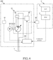
- the electric pump system 200 according to the second embodiment has: a resolver 52 serving as a rotation detection unit that acquires the rotation rate of the electric motor 50; the first acceleration sensor 61 serving as a first vibration detection unit that detects the vibration of the pump 10; and a second acceleration sensor 62 serving as a second vibration detection unit that detects the vibration of the CVT 2.
- the control device 60 compares the vibration of the electric pump 1 with the vibration of the CVT 2, and, when the frequency bands in which the amplitude is increased are overlapped, adjusts the operation of the electric pump 1 by determining that the determination condition is satisfied. A description will be given specifically below.
- the first acceleration sensor 61 has a similar configuration to that of the acceleration sensor 61 of the above-described first embodiment, the same reference numerals are assigned to the components, and detailed descriptions thereof will be omitted.
- the second acceleration sensor 62 is, for example, attached to the vehicle V on which the electric pump system 100 is mounted, and detects the vibration of the CVT 2. The detection result from the second acceleration sensor 62 is input to the control device 60.
- the resolver 52 is attached to the electric motor 50 and detects the rotation rate (rotation speed) of the electric motor 50. The detection result from the resolver 52 is input to the control device 60.
- the rotation rate of the pump 10 can be calculated from the rotation rate of the electric motor 50. In this embodiment, the rotation rate of the pump 10 is the same as the rotation rate of the electric motor 50.
- control device 60 executes the processing shown in FIG. 5 .
- step S20 the rotation rate of the electric motor 50 is acquired.
- step S21 a frequency analysis of the vibration generated in the pump 10 is performed on the basis of the detection result from the first acceleration sensor 61, and the relationship between the frequency band and the amplitude is acquired on the basis of the rotation rate of the electric motor 50 (see FIG. 6(A) ).
- the frequency analysis is performed by fast Fourier transform of the detection result from the first acceleration sensor 61.
- step S22 as shown in FIG. 6(A) , from the relationship between the frequency band and the amplitude acquired in step S21, the frequency band in which the amplitude is equal to or greater than a predetermined first amplitude threshold value (hereinafter, referred to as "a first frequency band”) is acquired.
- a predetermined first amplitude threshold value hereinafter, referred to as "a first frequency band
- step S23 similarly to step S21, the frequency analysis of the vibration generated in the CVT 2 is performed on the basis of the detection result from the second acceleration sensor 62, and the relationship between the frequency band and the amplitude is acquired on the basis of the rotation rate of the electric motor 50.
- step S24 similarly to step S22, as shown in FIG. 6(B) , from the relationship between the frequency band and the amplitude acquired in step S23, the frequency band in which the amplitude is equal to or greater than a predetermined second amplitude threshold value (hereinafter, referred to as "a second frequency band”) is acquired.
- a second frequency band a predetermined second amplitude threshold value
- step S25 it is determined whether the first frequency band acquired in step S22 overlaps with the second frequency band acquired in step S24.
- the first frequency band in which the amplitude of the vibration of the pump 10 is increased
- a region (the second frequency band), in which the amplitude of the vibration of the CVT 2 is increased are overlapped, it is considered that resonance is caused in the overlapped frequency band, and as a result, the amplitude is increased.
- the increase in the amplitude is caused in both of the pump 10 and the CVT 2 in the common frequency band, it is considered that the resonance is caused.
- the vibration is amplified as it is transmitted to the CVT 2 side, and only the CVT 2 side is subjected to a high vibration having a large amplitude.
- step S26 If it is determined that the determination condition is not satisfied, the process is terminated.
- Step S26 is the similar to step S12 in the first embodiment.
- step S26 is executed, the first embodiment is terminated. As described above, by changing the operation condition of the electric pump 1, it is possible to suppress the cause of the resonance.
- the electric pump system 200 when the amplitudes of the electric pump 1 and the CVT 2 are high in the common frequency band, it is determined that the resonance is caused and the operation of the electric pump 1 is adjusted. As a result, the operation of the electric pump 1 in the resonance region in which resonance is caused can be avoided, and so, it is possible to suppress the vibration of the electric pump 1 and the CVT 2.
- the operation of the electric pump 1 is controlled to suppress the vibration.
- the vibration may be reduced by controlling the operation of the electric pump 1 such that the order component of the vibration of the pump 10 and the order component of the vibration of the electric motor 50 do not overlap.
- the control device 60 calculates the frequency f of the order component for the first order to a predetermined order (for example, sixth order) for each of the pump 10 and the electric motor 50.
- the frequency of the order component may be calculated up to an arbitrarily predetermined order as described above, or the frequency of the order component may be calculated up to a predetermined frequency (for example, 3000 Hz).
- the control device 60 compares each frequency of the order component of the vibration of the pump 10 with each frequency of the order component of the vibration of the electric motor 50, and when they are overlapped, the control device 60 determines that the determination condition is satisfied and controls the operations of the pump 10 and the electric motor 50. Specifically, the control device 60 controls the rotation rate of the electric motor 50. By changing the rotation rate of the electric motor 50, the frequency of the pump 10 and the frequency of the electric motor 50, which were overlapped, for the order component will diverge. As a result, it is possible to reduce the vibration of the electric pump 1.
- the meaning of the phrase “the frequencies overlap with each other” is not limited to a case in which the frequencies coincide with each other, and also includes a case in which the difference of the frequencies is equal to or less than a predetermined value or in which the ratio of the frequencies falls within a predetermined range.
- the phrase "two frequencies are overlapped” means that a predetermined frequency regions, which are each set to have a numerical range including each of the frequencies, are overlapped with each other.
- the control device 60 may determine whether the determination condition is satisfied by comparing the resonance frequency region of the CVT 2 (the driving target object) with the respective order component(s) of the frequency(ies) of the pump 10 and/or the electric motor 50 described above. In this case, when the resonance frequency region of the CVT 2 overlaps with the respective order component(s) of the frequency(ies) of the pump 10 and/or the electric motor 50, the control device 60 determines that the determination condition is satisfied and controls the operations of the pump 10 and the electric motor 50.
- the resonance frequency region is set on the basis of the natural frequency of the CVT 2, and this is stored in advance in the control device 60.
- the acceleration sensor is first provided on the CVT 2 that is the driving target object, and the vibration data is acquired by sweeping the rotation rate of the pump 10 or the electric motor 50. Then, the vibration data is subjected to the frequency analysis, and from the frequencyamplitude-time (the rotation rate) graph, a certain frequency component (for example, 500 Hz) in which the vibration is always large even when the rotation rate is swept is specified as the resonance frequency region. If the resonance is to be suppressed for the electric pump system 200 instead of the driving target object, such as the CVT 2, etc., this can be achieved by applying the method described above to the electric pump system 200 instead of the CVT 2.
- FIGs. 7 and 8 an electric pump system 300 according to a third embodiment of the present invention will be described with reference to FIGs. 7 and 8 .
- differences from the above-described first embodiment will be mainly described, and the configurations that are the same as those in the above-described first embodiment are assigned the same reference numerals and descriptions thereof will be omitted.
- the electric pump system 300 according to the third embodiment does not includes the acceleration sensor 61 in the above-described first embodiment, and the first acceleration sensor 61 and the second acceleration sensor 62 in the second embodiment. Other configurations are the similar to those in the above-described first embodiment. In other words, the electric pump system 300 according to the third embodiment has a structure in which the configuration of the acceleration sensor 61 is removed from the structure shown in FIG. 1 .
- a control map (see FIG. 8 ) that indicates a combination of the rotation rate of the electric motor 50 and the opening degree of the solenoid valve 40 that causes the resonance is stored in the control device 60 in advance.
- control device 60 executes the processing shown in FIG. 7 .
- step S30 is similar to step S10 in the first embodiment (see FIG. 5 ), the description thereof will be omitted.
- step S31 the combination of the rotation rate of the electric motor 50 and the opening degree of the solenoid valve 40 (hereinafter, referred to as a "current operation condition") is compared with the control map.
- the control map includes a usage allowed condition that is the operation condition under which it is possible to use of the electric pump 1 without generating the vibration with the amplitude equal to or greater than a predetermined level to the electric pump 1 or the CVT 2 (the vehicle V) and a usage limited condition under which the vibration with the amplitude equal to or greater than a predetermined level is generated and the use the electric pump 1 is limited.
- Step S32 is similar to step S26 in the above-described first embodiment (see FIG. 5 ). Thereafter, steps S31 and S32 are repeatedly executed until it is determined as "NO" in step S31.
- the process is terminated.
- the vibration detection unit in the above-described first embodiment, the first vibration detection unit and the second vibration detection unit in the second embodiment are each the acceleration sensor.
- the vibration detection unit, the first vibration detection unit, and the second vibration detection unit may be any devices as long as they can detect vibration, and for example, it may be possible to employ a sound wave meter that detects sound waves generated by vibration.
- both of the opening degree of the solenoid valve 40 and the rotation rate of the electric motor 50 are adjusted when the determination condition is satisfied, only one of them may be adjusted. If only the adjustment of the opening degree of the solenoid valve 40 is to be performed, the control, in which the opening degree of the solenoid valve 40 is reduced to reduce the discharge capacity of the pump 10, is executed within a range in which the required flow amount is supplied to the CVT 2. Similarly, when only the adjustment of the rotation rate of the electric motor 50 is to be performed, the control, in which the rotation rate of the electric motor 50 is reduced, is executed within a range in which the flow amount required for the CVT 2 is supplied.
- first embodiment, the second embodiment, and the third embodiment are not mutually exclusive configurations and may be combined with each other. Two embodiments selected from three embodiments may be combined, or all of the embodiments may be combined.
- the electric pump system 100, 200, 300 includes: the pump 10 configured such that the discharge flow rate is controlled in accordance with the opening degree of the solenoid valve 40, the operation of the solenoid valve 40 being controlled by energization; the electric motor 50 configured to drive the pump 10; and the control device 60 configured to control the operations of the solenoid valve 40 of the pump 10 and the electric motor 50 based on the command signal indicating the required discharge flow rate or the required discharge pressure of the pump 10, wherein the control device 60 is configured to adjust the operation of at least one of the solenoid valve 40 and the electric motor 50 when the determination condition, which is for determination of whether a predetermined vibration is generated in the electric pump system 100, 200, 300 or the CVT 2, is satisfied.
- the operation condition includes two parameters, i.e., the opening degree of the solenoid valve 40 and the rotation rate of the electric motor 50, compared with a case in which only one parameter is included, it becomes easier to operate the electric pump system 100 under the operation condition capable of suppressing the vibration, while ensuring the required flow amount of the working oil.
- the electric pump system 100 is attached with the pump 10, the electric motor 50, and the pump 10 and has the acceleration sensor 61 configured to detect the vibration of any of the target objects to which the working fluid discharged from the pump 10 is supplied, wherein the control device 60 is configured to adjust the operation of at least one of the solenoid valve 40 and the electric motor 50 by determining that the determination condition is satisfied when the detection result from the acceleration sensor 61 exceeds a predetermined threshold value.
- the electric pump system 200 includes: the first acceleration sensor 61 configured to detect the vibration of the pump 10 or the electric motor 50; and the second acceleration sensor 62 configured to detect the vibration of the CVT 2 attached to the pump 10 to which the working oil discharged from the pump 10 is supplied, wherein the control device 60 is configured to: acquire the first frequency band in which the amplitude is equal to or greater than a predetermined first amplitude threshold value based on the detection result from the first vibration detection unit; acquire the second frequency band in which the amplitude is equal to or greater than a predetermined second amplitude threshold value based on the detection result from the second vibration detection unit; and adjust the operation of at least one of the solenoid valve 40 and the electric motor 50 by determining that the determination condition is satisfied when the first frequency band and the second frequency band are at least partially overlapped.
- control device 60 performs the frequency analysis on each of the results from the first acceleration sensor 61 and the second acceleration sensor 62 and compares the first frequency band and the second frequency band so as to determine whether they are overlapped.
- control map indicating the usage allowed condition under which the vibration equal to or greater than a predetermined level is not generated and the usage limited condition under which the vibration equal to or greater than a predetermined level is generated for the combination of the rotation rate of the electric motor 50 and the opening degree of the solenoid valve 40 is stored in the control device 60, and the control device 60 is configured to adjust the operation of at least one of the solenoid valve 40 and the electric motor 50 by determining that the determination condition is satisfied when the solenoid valve 40 and the electric motor 50 are operated under the operation condition under which the usage is limited.
- the electric pump system 200 further includes the resolver 52 configured to detect the rotation rate of the electric motor 50, wherein the pump 10 is a vane pump, and the control device 60 is configured to: calculate the frequency of the order component of the vibration of the pump 10 based on the number of vanes of the pump 10 and the detection result from the resolver 52; calculate the frequency of the order component of the vibration of the electric motor 50 based on any of the number of slots, the number of poles, and the least common multiple of the number of slots and the number of poles of the electric motor 50 and the detection result from the resolver 52; and adjust the operation of at least one of the solenoid valve 40 and the electric motor 50 by determining that the determination condition is satisfied when the frequency of the order component of the vibration of the pump 10 and the frequency of the order component of the vibration of the electric motor 50 are overlapped.
- the control device 60 is configured to: calculate the frequency of the order component of the vibration of the pump 10 based on the number of vanes of the pump 10 and the detection result from the resolver 52; calculate the frequency of
- the resonance frequency region which is the natural frequency of the CVT 2
- the control device 60 is configured to adjust the operation of at least one of the solenoid valve 40 and the electric motor 50 by determining that the determination condition is satisfied when at least one of the frequency of the order component of the vibration of the pump 10 and the frequency of the order component of the vibration of the electric motor 50 overlaps with the resonance frequency region.
- control device 60 is configured to, when the determination condition is satisfied, in order to ensure the required discharge flow rate of the pump 10, reduce the opening degree of the solenoid valve 40 and increase the rotation rate of the electric motor 50, or to increase the opening degree of the solenoid valve 40 and reduce the rotation rate of the electric motor 50.
Landscapes
- Engineering & Computer Science (AREA)
- Mechanical Engineering (AREA)
- General Engineering & Computer Science (AREA)
- Control Of Positive-Displacement Pumps (AREA)
Abstract
Description
- The present invention relates to an electric pump system.
-
JP1997-68172A - In the electric pump device as described in
JP1997-68172A - As object of the present invention is to provide an electric pump system capable of suppressing vibration.
- According to one aspect of the present invention, an electric pump system for supplying working fluid to a driving target object, and the electric pump system comprising: a pump configured such that a discharge flow rate is controlled in accordance with an opening degree of a solenoid valve, operation of the solenoid valve being controlled by energization; an electric motor configured to drive the pump; and a control device configured to control operations of the solenoid valve of the pump and the electric motor based on a command signal indicating a required discharge flow rate or a required discharge pressure of the pump, wherein the control device is configured to adjust the operation of at least one of the solenoid valve and the electric motor when a determination condition is satisfied, the determination condition being set based on vibration generated in the electric pump system or the driving target object.
-
- [
FIG. 1] FIG. 1 is a block diagram showing a configuration of an electric pump system according to a first embodiment of the present invention. - [
FIG. 2] FIG. 2 is a block diagram showing a configuration of a pump according to the first embodiment of the present invention. - [
FIG. 3] FIG. 3 is a flowchart showing a control method according to the first embodiment of the present invention. - [
FIG. 4] FIG. 4 is a block diagram showing the configuration of the electric pump system according to a second embodiment of the present invention. - [
FIG. 5] FIG. 5 is a flowchart showing the control method according to the second embodiment of the present invention. - [
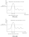
FIG. 6A] FIG. 6A is a graph showing vibration plotted with frequency on the horizontal axis and amplitude on the vertical axis, and is a diagram showing vibration generated in the pump. - [
FIG. 6B] FIG. 6B is a graph showing vibration plotted with frequency on the horizontal axis and amplitude on the vertical axis, and is a diagram showing vibration generated in a CVT. - [
FIG. 7] FIG. 7 is a flowchart showing the control method according to a third embodiment of the present invention. - [
FIG. 8] FIG. 8 is a diagram showing a control map according to the third embodiment of the present invention. - In the following, an
electric pump system 100 according to an embodiment of the present invention will be described with reference to the drawings. - The
electric pump system 100 is a device that supplies working fluid (working oil in this embodiment) to a driving target object (a fluid pressure apparatus) that is operated by the working fluid. In the following, a case in which theelectric pump system 100 is mounted on a vehicle V, and the working oil is supplied to a transmission, which includes a belt-driven type continuously variable transmission mechanism (hereinafter, referred to as "CVT 2"), serving as the driving target object will be described as an example. The driving target object may also be a fluid pressure control device of a construction machine, an automatic transmission of a vehicle, or the like. - As shown in
FIG. 1 , theelectric pump system 100 receives a command signal for controlling operation of aCVT 2 from an ECU 3 of the vehicle V, and supplies the working oil to theCVT 2 in accordance with the command signal. Theelectric pump system 100 includes: apump 10 of a variable displacement type; anelectric motor 50 that drives thepump 10; anacceleration sensor 61 serving as a vibration detection unit that detects vibration of an electric pump 1 that is configured with thepump 10 and theelectric motor 50; and acontrol device 60 that controls operations of thepump 10 and theelectric motor 50. - The
pump 10 is a variable displacement vane pump. In addition, thepump 10 is an unbalanced vane pump. As shown inFIG. 2 , thepump 10 includes: arotor 11 that is rotationally driven; a plurality ofvanes 12 that are provided in therotor 11 so as to be reciprocatable in the radial direction; and acam ring 13 that accommodates therotor 11 and thevanes 12. Therotor 11 is linked to arotation shaft 51 of theelectric motor 50 and is rotated together with therotation shaft 51 of theelectric motor 50. - The
vanes 12 are biased radially outward by a back pressure applied to thevanes 12 and a centrifugal force caused by the rotation of therotor 11, and tip end portions of thevanes 12 slide along an innercircumferential surface 13a of thecam ring 13. Therotor 11 and thecam ring 13 are provided between a pump body (not shown) and a pump cover (not shown), and a plurality ofpump chambers 14 are formed between therotor 11 and thecam ring 13 by being partitioned by therespective vanes 12. - The
cam ring 13 is decentered relative to the center of therotor 11. Therefore, thevanes 12 reciprocate along with the rotation of therotor 11, and thereby, thepump chambers 14 are expanded and contracted. As thepump chambers 14 expand, the working oil in a tank T is sucked into thepump chambers 14 through asuction passage 5a and a suction port (not shown). As thepump chambers 14 contract, the working oil is discharged from thepump chambers 14 through a discharge port (not shown). The discharged working oil is supplied to the CVT 2 by being guided by adischarge passage 5b. - A displacement volume (a discharge capacity) of the
pump 10 changes in response to an amount of eccentricity of thecam ring 13. Specifically, as the amount of eccentricity is reduced, the displacement volume is reduced. As the amount of eccentricity is increased, the displacement volume is increased. The displacement volume corresponds to discharge amount of the working oil per rotation of therotor 11.FIG. 2 shows a state in which thecam ring 13 is decentered to the maximum extent, and the displacement volume of thepump 10 is the maximum. - The
pump 10 includes anannular adapter ring 20 that surrounds thecam ring 13; acontrol valve 30 that controls the pressure between thecam ring 13 and theadapter ring 20; and asolenoid valve 40 that controls the operating characteristics of thecontrol valve 30. - The
adapter ring 20 supports thecam ring 13 so as to be swingable via asupport pin 21. As thecam ring 13 swings relative to theadapter ring 20, the amount of eccentricity with respect to the center of therotor 11 is changed. - A space between the
cam ring 13 and theadapter ring 20 is divided into a firstfluid pressure chamber 20a and a secondfluid pressure chamber 20b by thesupport pin 21 and aseal member 22 that is provided on an inner circumference of theadapter ring 20. When thecam ring 13 swings in the direction in which the firstfluid pressure chamber 20a is expanded and the secondfluid pressure chamber 20b becomes smaller (the right direction inFIG. 2 ), the amount of eccentricity is reduced. When thecam ring 13 swings in the direction in which the firstfluid pressure chamber 20a becomes smaller and the secondfluid pressure chamber 20b is expanded (the left direction inFIG. 2 ), the amount of eccentricity is increased. - The swing of the
cam ring 13 is caused by a pressure difference between the firstfluid pressure chamber 20a and the secondfluid pressure chamber 20b. The firstfluid pressure chamber 20a and the secondfluid pressure chamber 20b are connected to the tank T via thecontrol valve 30, and the pressure in each of the firstfluid pressure chamber 20a and the secondfluid pressure chamber 20b is controlled by using thecontrol valve 30. The secondfluid pressure chamber 20b is connected to thedischarge passage 5b at the upstream side of thesolenoid valve 40 via afixed restrictor 5c. - The
control valve 30 is selectively switched between afirst position 30a or asecond position 30b in response to the pressure difference between the upstream side and the downstream side of thesolenoid valve 40. At thefirst position 30a, thecontrol valve 30 allows the communication between the firstfluid pressure chamber 20a and the tank T, and on the other hand, shuts off the communication between the secondfluid pressure chamber 20b and the tank T. At thesecond position 30b, thecontrol valve 30 shuts off the communication between the firstfluid pressure chamber 20a and the tank T, and on the other hand, allows the communication between the secondfluid pressure chamber 20b and the tank T via avariable restrictor 31. Thevariable restrictor 31 is formed such that an opening area is increased as the pressure difference between the upstream side and the downstream side of thesolenoid valve 40 is increased. - The
solenoid valve 40 adjusts an opening degree of thedischarge passage 5b in accordance with the current supplied from thecontrol device 60. By adjusting the opening degree of thedischarge passage 5b, the pressure difference between the upstream side and the downstream side of thesolenoid valve 40 is adjusted. Thesolenoid valve 40 has asolenoid 41 that biases a valve body (not shown) in the direction in which thedischarge passage 5b is closed and aspring 42 that biases the valve body against thesolenoid 41. - When the pressure difference between the upstream side and the downstream side of the
solenoid valve 40 is smaller than a predetermined value, thecontrol valve 30 is maintained at thefirst position 30a by a biasing force exerted by areturn spring 32. - At this time, the first
fluid pressure chamber 20a communicates with the tank T via thecontrol valve 30, and the pressure in the firstfluid pressure chamber 20a becomes equal to the tank pressure. On the other hand, the communication between the secondfluid pressure chamber 20b and the tank T is shut off by thecontrol valve 30. Because the working oil in thedischarge passage 5b is guided to the secondfluid pressure chamber 20b, thecam ring 13 is biased in the left direction inFIG. 2 by the pressure in the secondfluid pressure chamber 20b and is held at the position where thecam ring 13 is decentered to the maximum extent. As a result, the displacement volume of thepump 10 is maximized. - When the pressure difference between the upstream side and the downstream side of the
solenoid valve 40 reaches a predetermined value due to an increase in the rotation rate of therotor 11 or an increase in the amount of current supplied thesolenoid 41, thecontrol valve 30 is switched to thesecond position 30b. Thus, thecontrol valve 30 shuts off the communication between the firstfluid pressure chamber 20a and the tank T, and on the other hand, allows the communication between the firstfluid pressure chamber 20a and thedischarge passage 5b. Therefore, the pressure in the firstfluid pressure chamber 20a is increased. In addition, thecontrol valve 30 allows the communication between the secondfluid pressure chamber 20b and the tank T via thevariable restrictor 31. Therefore, the pressure in the secondfluid pressure chamber 20b is reduced, and thecam ring 13 swings to the right direction inFIG. 1 by the pressure in the firstfluid pressure chamber 20a. As a result, the amount of eccentricity is reduced, and the displacement volume of thepump 10 is reduced. - As described above, in the
electric pump system 100, by controlling the rotation rate of the rotor 11 (the rotation rate of the electric motor 50) and the amount of current supplied to thesolenoid valve 40, it is possible to adjust the displacement volume of thepump 10 to adjust the discharge flow rate of thepump 10. - The
acceleration sensor 61 is attached to a position where vibration generated in the electric pump 1 can be measured. For example, theacceleration sensor 61 is provided on a bracket portion (not shown) with which theelectric motor 50 is attached to the vehicle V. The position to which theacceleration sensor 61 is attached is not limited thereto, and it may be set arbitrarily. However, it is desirable to detect the vibration at a position as close to the vehicle V (a mother unit) as possible. In addition, theacceleration sensor 61 may be attached to both of theelectric motor 50 and thepump 10. A detection result (the amplitude) from theacceleration sensor 61 is input to thecontrol device 60. Theacceleration sensor 61 may be provided on the side of the vehicle V such as theCVT 2, etc., which is the driving target object. - The
control device 60 is an ECU configured with a microcomputer including a CPU (a central processing unit), a ROM (a read-only memory), a RAM (a random-access memory), and an I/O interface (an input/output interface). The RAM stores data for processing executed by the CPU, the ROM pre-stores a control program, etc. for the CPU, and the I/O interface is used for input/output of information to/from a device connected to thecontrol device 60. Thecontrol device 60 is programmed to be capable of executing at least a process necessary for executing the control according to this embodiment and modifications. Thecontrol device 60 may be configured as a single device, or may be configured to be divided into a plurality of devices such that controls are respectively executed by the plurality of devices in a distributed processing. - The
control device 60 controls the operations of theelectric motor 50 and thepump 10 so as to be capable of executing the control method of the electric pump 1 described in this description. -
FIG. 3 is a flowchart showing the control method of the electric pump 1 executed by thecontrol device 60. When, for example, an ignition switch of the vehicle V is turned ON, and theelectric pump system 100 is activated, thecontrol device 60 executes the processing shown inFIG. 3 at predetermined time intervals. - In step S10, the rotation rate of the
electric motor 50 and the opening degree of thesolenoid valve 40 are adjusted so as to achieve the flow amount and the pressure in accordance with the command signal. - In step S11, it is determined whether or not the determination condition, which is set on the basis of the vibration generated in the electric pump 1, is satisfied. Specifically, the determination condition is whether the vibration detected by the
acceleration sensor 61 is equal to or greater than a predetermined vibration threshold value. For example, the vibration threshold value corresponds to a value of the amplitude of the vibration when resonance is caused in the electric pump 1. If the vibration detected by theacceleration sensor 61 is equal to or greater than the vibration threshold value, it is determined that the determination condition is satisfied, and the process proceeds to step S12. In other words, the case in which the determination condition is satisfied is a case in which the electric pump 1 is operated at the resonance frequency. If the vibration detected by theacceleration sensor 61 is less than the threshold value, the process is terminated. - In step S12, the operation of the electric pump 1 is controlled such that the rotation rate of the
electric motor 50 is reduced (in other words, the amount of current supplied to theelectric motor 50 is reduced) and such that the opening degree of thesolenoid valve 40 is increased (in other words, the amount of current supplied to thesolenoid valve 40 is increased). Subsequently, steps S11 and S12 are repeatedly executed until it is determined as NO in step S11. - By increasing the opening degree of the
solenoid valve 40, the displacement volume of thepump 10 is increased to increase the discharge amount per rotation. Therefore, even if the rotation rate of theelectric motor 50 is reduced, the supply of the working oil at the flow amount and the pressure according to the command signal is maintained without reducing the flow amount of the working oil discharged by thepump 10. In other words, in step S12, the rotation rate of theelectric motor 50 is reduced and the opening degree of thesolenoid valve 40 is increased such that the flow amount of the working oil discharged by thepump 10 is maintained at (or does not fall below) the flow amount according to the command signal. - In addition, because the rotation rate of the
electric motor 50 is reduced, it is possible to change the frequency of the vibration generated in theelectric motor 50. By changing the frequency of the vibration of theelectric motor 50, it is possible to suppress the vibration of the electric pump 1. - In step S12, the rotation rate of the
electric motor 50 may be increased, and the opening degree of thesolenoid valve 40 may be reduced. Even in such a case, it is possible to change the frequency of the vibration generated in theelectric motor 50 and to suppress occurrence of the resonance while ensuring the required flow amount for the flow amount of the working oil discharged by the electric pump 1. - According to the above-described embodiment, the advantages described below are afforded.
- With the
electric pump system 100, when the vibration generated in the electric pump 1 becomes equal to or greater than the vibration threshold value, the rotation rate of theelectric motor 50 is adjusted while maintaining a supply flow amount to theCVT 2. As a result, because the operation of theelectric motor 50 in the resonance region in which resonance is caused can be avoided, it is possible to suppress the vibration in the electric pump 1. - Especially, in a case in which the pump is an unbalanced variable displacement vane pump, compared with a case in which the pump is a balanced pump, the vibration is more likely to be generated. Even in such a case, the
electric pump system 100 according to this embodiment is particularly useful because the vibration can be suppressed by adjusting the the operation condition. - Next, an
electric pump system 200 according to a second embodiment of the present invention will be described with reference toFIGs. 4 to 6 . In the following, differences from the above-described first embodiment will be mainly described, and the configurations that are the same as those in the above-described first embodiment are assigned the same reference numerals and descriptions thereof will be omitted. - In the above-described first embodiment, the
electric pump system 100 has theacceleration sensor 61 that detects the vibration of the electric pump 1. Thecontrol device 60 controls the operation of the electric pump 1 by determining, as the determination condition, whether the vibration detected by theacceleration sensor 61 is equal to or greater than the vibration threshold value. - In contrast, in the
electric pump system 200 according to the second embodiment, it is determined whether it is the operation condition (the determination condition) under which the vibration is likely to be generated by comparing the vibration generated in thepump 10, theelectric motor 50, or theCVT 2. Specifically, as shown inFIG. 4 , theelectric pump system 200 according to the second embodiment has: aresolver 52 serving as a rotation detection unit that acquires the rotation rate of theelectric motor 50; thefirst acceleration sensor 61 serving as a first vibration detection unit that detects the vibration of thepump 10; and a second acceleration sensor 62 serving as a second vibration detection unit that detects the vibration of theCVT 2. Thecontrol device 60 compares the vibration of the electric pump 1 with the vibration of theCVT 2, and, when the frequency bands in which the amplitude is increased are overlapped, adjusts the operation of the electric pump 1 by determining that the determination condition is satisfied. A description will be given specifically below. - Because the
first acceleration sensor 61 has a similar configuration to that of theacceleration sensor 61 of the above-described first embodiment, the same reference numerals are assigned to the components, and detailed descriptions thereof will be omitted. - The second acceleration sensor 62 is, for example, attached to the vehicle V on which the
electric pump system 100 is mounted, and detects the vibration of theCVT 2. The detection result from the second acceleration sensor 62 is input to thecontrol device 60. - The
resolver 52 is attached to theelectric motor 50 and detects the rotation rate (rotation speed) of theelectric motor 50. The detection result from theresolver 52 is input to thecontrol device 60. In addition, because thepump 10 is connected to theelectric motor 50, the rotation rate of thepump 10 can be calculated from the rotation rate of theelectric motor 50. In this embodiment, the rotation rate of thepump 10 is the same as the rotation rate of theelectric motor 50. - In the following, the control method of the electric pump 1 according to the second embodiment will be described.
- In the second embodiment, the
control device 60 executes the processing shown inFIG. 5 . - In step S20, the rotation rate of the
electric motor 50 is acquired. - In step S21, a frequency analysis of the vibration generated in the
pump 10 is performed on the basis of the detection result from thefirst acceleration sensor 61, and the relationship between the frequency band and the amplitude is acquired on the basis of the rotation rate of the electric motor 50 (seeFIG. 6(A) ). The frequency analysis is performed by fast Fourier transform of the detection result from thefirst acceleration sensor 61. - In step S22, as shown in
FIG. 6(A) , from the relationship between the frequency band and the amplitude acquired in step S21, the frequency band in which the amplitude is equal to or greater than a predetermined first amplitude threshold value (hereinafter, referred to as "a first frequency band") is acquired. - In step S23, similarly to step S21, the frequency analysis of the vibration generated in the
CVT 2 is performed on the basis of the detection result from the second acceleration sensor 62, and the relationship between the frequency band and the amplitude is acquired on the basis of the rotation rate of theelectric motor 50. - In step S24, similarly to step S22, as shown in
FIG. 6(B) , from the relationship between the frequency band and the amplitude acquired in step S23, the frequency band in which the amplitude is equal to or greater than a predetermined second amplitude threshold value (hereinafter, referred to as "a second frequency band") is acquired. - In step S25, it is determined whether the first frequency band acquired in step S22 overlaps with the second frequency band acquired in step S24.
- Here, when a region (the first frequency band), in which the amplitude of the vibration of the
pump 10 is increased, and a region (the second frequency band), in which the amplitude of the vibration of theCVT 2 is increased, are overlapped, it is considered that resonance is caused in the overlapped frequency band, and as a result, the amplitude is increased. In other words, when the increase in the amplitude is caused in both of thepump 10 and theCVT 2 in the common frequency band, it is considered that the resonance is caused. Thus, by determining whether the first frequency band and the second frequency band are overlapped, it is possible to determine whether is increased resonance is caused. - Although when low vibration having a small amplitude is generated on the
pump 10 side, depending on the natural frequency of theCVT 2, there may be a case in which the vibration is amplified as it is transmitted to theCVT 2 side, and only theCVT 2 side is subjected to a high vibration having a large amplitude. In such a case, it is preferable to provide theacceleration sensor 61 on the side of the vehicle V, such as theCVT 2, etc., which is the driving target object, and to perform the determination by using the control as in the first embodiment. - When the first frequency band and the second frequency band are at least partially overlapped, it is determined that the determination condition is satisfied, and the process proceeds to step S26. If it is determined that the determination condition is not satisfied, the process is terminated.
- Step S26 is the similar to step S12 in the first embodiment. When step S26 is executed, the first embodiment is terminated. As described above, by changing the operation condition of the electric pump 1, it is possible to suppress the cause of the resonance.
- According to the above-described embodiment, the advantages described below are afforded.
- In the
electric pump system 200, when the amplitudes of the electric pump 1 and theCVT 2 are high in the common frequency band, it is determined that the resonance is caused and the operation of the electric pump 1 is adjusted. As a result, the operation of the electric pump 1 in the resonance region in which resonance is caused can be avoided, and so, it is possible to suppress the vibration of the electric pump 1 and theCVT 2. - Next, a modification of the second embodiment will be described.
- In the above-described second embodiment, when the region (the first frequency band), in which the amplitude of the vibration of the
pump 10 is increased, and the region (the second frequency band), in which the amplitude of the vibration of theCVT 2 is increased, are overlapped, the operation of the electric pump 1 is controlled to suppress the vibration. In contrast, the vibration may be reduced by controlling the operation of the electric pump 1 such that the order component of the vibration of thepump 10 and the order component of the vibration of theelectric motor 50 do not overlap. A description will be given specifically below. - The frequency f of the order component is represented by f = n × z × N/60 [Hz], wherein: n is an order; z is the number of vanes for the
pump 10, or z is any of the number of slots, the number of poles, and the least common multiple of the number of slots and the number of poles for theelectric motor 50; N is the rotation rate; and f is the frequency of the order component. The rotation rates of thepump 10 and theelectric motor 50 can be acquired from the detection result from theresolver 52. For example, when the rotation rate is 600 [rpm] and the number of vanes of thepump 10 is 10, the frequency of a first order component (the order component) of thepump 10 is f = 1 × 10 × 600/60 = 100 [Hz]. - The
control device 60 calculates the frequency f of the order component for the first order to a predetermined order (for example, sixth order) for each of thepump 10 and theelectric motor 50. The frequency of the order component may be calculated up to an arbitrarily predetermined order as described above, or the frequency of the order component may be calculated up to a predetermined frequency (for example, 3000 Hz). Thecontrol device 60 then compares each frequency of the order component of the vibration of thepump 10 with each frequency of the order component of the vibration of theelectric motor 50, and when they are overlapped, thecontrol device 60 determines that the determination condition is satisfied and controls the operations of thepump 10 and theelectric motor 50. Specifically, thecontrol device 60 controls the rotation rate of theelectric motor 50. By changing the rotation rate of theelectric motor 50, the frequency of thepump 10 and the frequency of theelectric motor 50, which were overlapped, for the order component will diverge. As a result, it is possible to reduce the vibration of the electric pump 1. - In the comparison of the respective order components, not only the determination of whether the order components coincide with each other, but also the determination of whether the difference or the ratio of the order components is equal to or less than a predetermined value may be performed. In other words, the meaning of the phrase "the frequencies overlap with each other" is not limited to a case in which the frequencies coincide with each other, and also includes a case in which the difference of the frequencies is equal to or less than a predetermined value or in which the ratio of the frequencies falls within a predetermined range. From another point of view, in this description, the phrase "two frequencies are overlapped" means that a predetermined frequency regions, which are each set to have a numerical range including each of the frequencies, are overlapped with each other.
- In addition, instead of or in addition to the comparison of the order components of the frequencies of the
pump 10 and theelectric motor 50, thecontrol device 60 may determine whether the determination condition is satisfied by comparing the resonance frequency region of the CVT 2 (the driving target object) with the respective order component(s) of the frequency(ies) of thepump 10 and/or theelectric motor 50 described above. In this case, when the resonance frequency region of theCVT 2 overlaps with the respective order component(s) of the frequency(ies) of thepump 10 and/or theelectric motor 50, thecontrol device 60 determines that the determination condition is satisfied and controls the operations of thepump 10 and theelectric motor 50. The resonance frequency region is set on the basis of the natural frequency of theCVT 2, and this is stored in advance in thecontrol device 60. As a result, because the overlap between the resonance frequency region of theCVT 2, etc. and the order component(s) of thepump 10 and/or theelectric motor 50 can be avoided, it is possible to suppress the vibration due to the resonance. - In the following, a method of setting the resonance frequency region will be described specifically. The acceleration sensor is first provided on the
CVT 2 that is the driving target object, and the vibration data is acquired by sweeping the rotation rate of thepump 10 or theelectric motor 50. Then, the vibration data is subjected to the frequency analysis, and from the frequencyamplitude-time (the rotation rate) graph, a certain frequency component (for example, 500 Hz) in which the vibration is always large even when the rotation rate is swept is specified as the resonance frequency region. If the resonance is to be suppressed for theelectric pump system 200 instead of the driving target object, such as theCVT 2, etc., this can be achieved by applying the method described above to theelectric pump system 200 instead of theCVT 2. - Next, an electric pump system 300 according to a third embodiment of the present invention will be described with reference to
FIGs. 7 and8 . In the following, differences from the above-described first embodiment will be mainly described, and the configurations that are the same as those in the above-described first embodiment are assigned the same reference numerals and descriptions thereof will be omitted. - The electric pump system 300 according to the third embodiment does not includes the
acceleration sensor 61 in the above-described first embodiment, and thefirst acceleration sensor 61 and the second acceleration sensor 62 in the second embodiment. Other configurations are the similar to those in the above-described first embodiment. In other words, the electric pump system 300 according to the third embodiment has a structure in which the configuration of theacceleration sensor 61 is removed from the structure shown inFIG. 1 . - In the electric pump system 300, a control map (see
FIG. 8 ) that indicates a combination of the rotation rate of theelectric motor 50 and the opening degree of thesolenoid valve 40 that causes the resonance is stored in thecontrol device 60 in advance. When the electric pump 1 is operated under the operation condition that causes the resonance included in the control map, it is determined that the determination condition is satisfied and the operation of the electric pump 1 is adjusted. A description will be given specifically below. - In the following, the control method of the electric pump 1 according to the third embodiment will be described.
- In the third embodiment, the
control device 60 executes the processing shown inFIG. 7 . - Because step S30 is similar to step S10 in the first embodiment (see
FIG. 5 ), the description thereof will be omitted. - In step S31, the combination of the rotation rate of the
electric motor 50 and the opening degree of the solenoid valve 40 (hereinafter, referred to as a "current operation condition") is compared with the control map. As shown inFIG. 8 , the control map includes a usage allowed condition that is the operation condition under which it is possible to use of the electric pump 1 without generating the vibration with the amplitude equal to or greater than a predetermined level to the electric pump 1 or the CVT 2 (the vehicle V) and a usage limited condition under which the vibration with the amplitude equal to or greater than a predetermined level is generated and the use the electric pump 1 is limited. When the current operation condition matches the usage limited condition included in the control map, it is determined that the determination condition is satisfied and the process proceeds to step S32, and thereby, the operation of the electric pump 1 is controlled. Step S32 is similar to step S26 in the above-described first embodiment (seeFIG. 5 ). Thereafter, steps S31 and S32 are repeatedly executed until it is determined as "NO" in step S31. When the current operation condition matches the usage allowed condition included in the control map, the process is terminated. - It is possible to create the control map by conducting experiments in advance to investigate the combination of the rotation rate of the
electric motor 50 and the opening degree of thesolenoid valve 40 with which the resonance is caused and the vibration is increased. - Also with the third embodiment described above, because the operation of the electric pump 1 under the operation condition that causes the resonance is avoided, it is possible to suppress the generation of the vibration.
- Next, modifications of present embodiments will be described. The following modifications also fall within the scope of the present invention, and it is also possible to combine the configurations shown in the modifications with the configurations described in the above embodiments, or to combine the configurations described in the following different modifications with each other.
- The vibration detection unit in the above-described first embodiment, the first vibration detection unit and the second vibration detection unit in the second embodiment are each the acceleration sensor. In contrast, the vibration detection unit, the first vibration detection unit, and the second vibration detection unit may be any devices as long as they can detect vibration, and for example, it may be possible to employ a sound wave meter that detects sound waves generated by vibration.
- In addition, in each of the embodiments described above, although both of the opening degree of the
solenoid valve 40 and the rotation rate of theelectric motor 50 are adjusted when the determination condition is satisfied, only one of them may be adjusted. If only the adjustment of the opening degree of thesolenoid valve 40 is to be performed, the control, in which the opening degree of thesolenoid valve 40 is reduced to reduce the discharge capacity of thepump 10, is executed within a range in which the required flow amount is supplied to theCVT 2. Similarly, when only the adjustment of the rotation rate of theelectric motor 50 is to be performed, the control, in which the rotation rate of theelectric motor 50 is reduced, is executed within a range in which the flow amount required for theCVT 2 is supplied. - The above-described first embodiment, the second embodiment, and the third embodiment are not mutually exclusive configurations and may be combined with each other. Two embodiments selected from three embodiments may be combined, or all of the embodiments may be combined.
- The configurations, operations, and effects of the embodiment of the present invention will be collectively described below.
- The
electric pump system pump 10 configured such that the discharge flow rate is controlled in accordance with the opening degree of thesolenoid valve 40, the operation of thesolenoid valve 40 being controlled by energization; theelectric motor 50 configured to drive thepump 10; and thecontrol device 60 configured to control the operations of thesolenoid valve 40 of thepump 10 and theelectric motor 50 based on the command signal indicating the required discharge flow rate or the required discharge pressure of thepump 10, wherein thecontrol device 60 is configured to adjust the operation of at least one of thesolenoid valve 40 and theelectric motor 50 when the determination condition, which is for determination of whether a predetermined vibration is generated in theelectric pump system CVT 2, is satisfied. - With this configuration, when the
solenoid valve 40 and theelectric motor 50 are operated under the operation condition under which a predetermined vibration is generated, the operation of at least one of thesolenoid valve 40 and theelectric motor 50 is adjusted. As a result, it is possible to suppress the generation of the vibration of theelectric pump system 100. In addition, because the operation condition includes two parameters, i.e., the opening degree of thesolenoid valve 40 and the rotation rate of theelectric motor 50, compared with a case in which only one parameter is included, it becomes easier to operate theelectric pump system 100 under the operation condition capable of suppressing the vibration, while ensuring the required flow amount of the working oil. - In addition, the
electric pump system 100 is attached with thepump 10, theelectric motor 50, and thepump 10 and has theacceleration sensor 61 configured to detect the vibration of any of the target objects to which the working fluid discharged from thepump 10 is supplied, wherein thecontrol device 60 is configured to adjust the operation of at least one of thesolenoid valve 40 and theelectric motor 50 by determining that the determination condition is satisfied when the detection result from theacceleration sensor 61 exceeds a predetermined threshold value. - With this configuration, because the operations of the
solenoid valve 40 and theelectric motor 50 is adjusted on the basis of the detected vibration, it is possible to suppress the vibration more reliably. - In addition, the
electric pump system 200 includes: thefirst acceleration sensor 61 configured to detect the vibration of thepump 10 or theelectric motor 50; and the second acceleration sensor 62 configured to detect the vibration of theCVT 2 attached to thepump 10 to which the working oil discharged from thepump 10 is supplied, wherein thecontrol device 60 is configured to: acquire the first frequency band in which the amplitude is equal to or greater than a predetermined first amplitude threshold value based on the detection result from the first vibration detection unit; acquire the second frequency band in which the amplitude is equal to or greater than a predetermined second amplitude threshold value based on the detection result from the second vibration detection unit; and adjust the operation of at least one of thesolenoid valve 40 and theelectric motor 50 by determining that the determination condition is satisfied when the first frequency band and the second frequency band are at least partially overlapped. - In addition, in the
electric pump system 200, thecontrol device 60 performs the frequency analysis on each of the results from thefirst acceleration sensor 61 and the second acceleration sensor 62 and compares the first frequency band and the second frequency band so as to determine whether they are overlapped. - With these configurations, by performing the determination on the basis of the vibrations of both of the
electric pump system 200 and theCVT 2, it is possible to determine the resonances of theelectric pump system 200 and theCVT 2, and to suppress the vibrations of theelectric pump system 200 and the vehicle V as a whole. - In addition, with the electric pump system 300, the control map indicating the usage allowed condition under which the vibration equal to or greater than a predetermined level is not generated and the usage limited condition under which the vibration equal to or greater than a predetermined level is generated for the combination of the rotation rate of the
electric motor 50 and the opening degree of thesolenoid valve 40 is stored in thecontrol device 60, and thecontrol device 60 is configured to adjust the operation of at least one of thesolenoid valve 40 and theelectric motor 50 by determining that the determination condition is satisfied when thesolenoid valve 40 and theelectric motor 50 are operated under the operation condition under which the usage is limited. - With this configuration, even if the sensor, etc. for detecting the vibration is not used, it is possible to avoid the operation of the electric pump 1 under the operation condition that is likely to generate the vibration.
- In addition, the
electric pump system 200 further includes theresolver 52 configured to detect the rotation rate of theelectric motor 50, wherein thepump 10 is a vane pump, and thecontrol device 60 is configured to: calculate the frequency of the order component of the vibration of thepump 10 based on the number of vanes of thepump 10 and the detection result from theresolver 52; calculate the frequency of the order component of the vibration of theelectric motor 50 based on any of the number of slots, the number of poles, and the least common multiple of the number of slots and the number of poles of theelectric motor 50 and the detection result from theresolver 52; and adjust the operation of at least one of thesolenoid valve 40 and theelectric motor 50 by determining that the determination condition is satisfied when the frequency of the order component of the vibration of thepump 10 and the frequency of the order component of the vibration of theelectric motor 50 are overlapped. - With this configuration, it is possible to suppress the vibration which is amplified by the overlap of the frequencies of the order components of the
pump 10 and theelectric motor 50. - In addition, in the
electric pump system 200, the resonance frequency region, which is the natural frequency of theCVT 2, is stored in advance in thecontrol device 60, and thecontrol device 60 is configured to adjust the operation of at least one of thesolenoid valve 40 and theelectric motor 50 by determining that the determination condition is satisfied when at least one of the frequency of the order component of the vibration of thepump 10 and the frequency of the order component of the vibration of theelectric motor 50 overlaps with the resonance frequency region. - With this configuration, it is possible to suppress the amplification of the resonance vibration of the
electric pump system 200 and theCVT 2. - In addition, in the
electric pump system control device 60 is configured to, when the determination condition is satisfied, in order to ensure the required discharge flow rate of thepump 10, reduce the opening degree of thesolenoid valve 40 and increase the rotation rate of theelectric motor 50, or to increase the opening degree of thesolenoid valve 40 and reduce the rotation rate of theelectric motor 50. - With this configuration, it is possible to suppress the generation of the vibration by changing the frequencies of the vibrations of both of the
pump 10 and theelectric motor 50 while supplying the required flow amount to theCVT 2. - Embodiments of this invention were described above, but the above embodiments are merely examples of applications of this invention, and the technical scope of this invention is not limited to the specific constitutions of the above embodiments.
- This application claims priority based on
Japanese Patent Application No.2022-59450 filed with the Japan Patent Office on March 31, 2022
Claims (7)
- An electric pump system for supplying working fluid to a driving target object, and the electric pump system comprising:a pump configured such that a discharge flow rate is controlled in accordance with an opening degree of a solenoid valve, operation of the solenoid valve being controlled by energization;an electric motor configured to drive the pump; anda control device configured to control operations of the solenoid valve of the pump and the electric motor based on a command signal indicating a required discharge flow rate or a required discharge pressure of the pump, whereinthe control device is configured to adjust the operation of at least one of the solenoid valve and the electric motor when a determination condition is satisfied, the determination condition being set based on vibration generated in the electric pump system or the driving target object.
- The electric pump system according to Claim 1, further comprisinga vibration detection unit configured to detect vibration of any of the pump, the electric motor, and the driving target object, whereinthe control device is configured to adjust the operations of at least one of the solenoid valve and the electric motor by determining that the determination condition is satisfied when a detection result from the vibration detection unit exceeds a predetermined threshold value.
- The electric pump system according to Claim 1, further comprising:a first vibration detection unit configured to detect vibration of the pump or the electric motor; anda second vibration detection unit configured to detect vibration of the driving target object, whereinthe control device is configured to:acquire a first frequency band in which amplitude is equal to or greater than a predetermined first amplitude threshold value based on a detection result from the first vibration detection unit;acquire a second frequency band in which amplitude is equal to or greater than a predetermined second amplitude threshold value based on a detection result from the second vibration detection unit; andadjust the operations of at least one of the solenoid valve and the electric motor by determining that the determination condition is satisfied when the first frequency band and the second frequency band are at least partially overlapped.
- The electric pump system according to Claim 1, further comprisinga rotation detection unit configured to detect a rotation rate of the electric motor, whereinthe pump is a vane pump, andthe control device is configured to:calculate a frequency of an order component of the vibration of the pump based on a number of vanes of the pump and a detection result from the rotation detection unit;calculate a frequency of an order component of the vibration of the electric motor based on any of a number of slots, a number of poles, and a least common multiple of the number of slots and the number of poles of the electric motor, and on the detection result from the rotation detection unit; andadjust the operations of at least one of the solenoid valve and the electric motor by determining that the determination condition is satisfied when the frequency of the order component of the vibration of the pump and the frequency of the order component of the vibration of the electric motor are overlapped.
- The electric pump system according to Claim 4, whereina resonance frequency region, which is a natural frequency of the driving target object, is stored in advance in the control device, andthe control device is configured to adjust the operations of at least one of the solenoid valve and the electric motor by determining that the determination condition is satisfied when at least one of the frequency of the order component of the vibration of the pump and the frequency of the order component of the vibration of the electric motor overlaps with the resonance frequency region.
- The electric pump system according to Claim 1, whereina control map indicating a usage limited condition under which vibration equal to or greater than a predetermined level is generated for a combination of the rotation rate of the electric motor and the opening degree of the solenoid valve is stored in the control device, andthe control device is configured to adjust the operations of at least one of the solenoid valve and the electric motor by determining that the determination condition is satisfied when the solenoid valve and the electric motor are operated under the usage limited condition.
- The electric pump system according to Claim 1, wherein
the control device is configured to, when the determination condition is satisfied, in order to ensure the required discharge flow rate of the pump, reduce the opening degree of the solenoid valve and increase the rotation rate of the electric motor, or to increase the opening degree of the solenoid valve and reduce the rotation rate of the electric motor.
Applications Claiming Priority (2)
| Application Number | Priority Date | Filing Date | Title |
|---|---|---|---|
| JP2022059450A JP7826096B2 (en) | 2022-03-31 | 2022-03-31 | Electric Pump System |
| PCT/JP2023/000324 WO2023188676A1 (en) | 2022-03-31 | 2023-01-10 | Electric pump system |
Publications (2)
| Publication Number | Publication Date |
|---|---|
| EP4502382A1 true EP4502382A1 (en) | 2025-02-05 |
| EP4502382A4 EP4502382A4 (en) | 2026-04-01 |
Family
ID=88200100
Family Applications (1)
| Application Number | Title | Priority Date | Filing Date |
|---|---|---|---|
| EP23778716.3A Pending EP4502382A4 (en) | 2022-03-31 | 2023-01-10 | ELECTRIC PUMP SYSTEM |
Country Status (5)
| Country | Link |
|---|---|
| US (1) | US20250215872A1 (en) |
| EP (1) | EP4502382A4 (en) |
| JP (1) | JP7826096B2 (en) |
| CN (1) | CN118922625A (en) |
| WO (1) | WO2023188676A1 (en) |
Families Citing this family (1)
| Publication number | Priority date | Publication date | Assignee | Title |
|---|---|---|---|---|
| JP7831704B2 (en) | 2023-09-15 | 2026-03-17 | 株式会社レゾナック | Image processing device, image processing method, and program |
Family Cites Families (11)
| Publication number | Priority date | Publication date | Assignee | Title |
|---|---|---|---|---|
| US4953109A (en) * | 1989-10-16 | 1990-08-28 | Design-Rite, Inc. | Automated trash compactor system |
| JP2675730B2 (en) * | 1992-12-25 | 1997-11-12 | 株式会社日立製作所 | Variable capacity compressor |
| SE9303824L (en) * | 1993-11-18 | 1994-10-10 | Pressmaster Tool Ab | Process for operating a hydraulic working tool and device for carrying out the process |
| US7621123B2 (en) * | 2006-01-20 | 2009-11-24 | Jacobs Michael H | Actuator control system and method |
| DE202007012542U1 (en) * | 2007-09-06 | 2007-11-08 | Alfons Haar Maschinenbau Gmbh & Co. Kg | Device for conveying liquids |
| WO2012114794A1 (en) * | 2011-02-21 | 2012-08-30 | 日立建機株式会社 | Electric construction machine |
| JP6510796B2 (en) * | 2014-11-07 | 2019-05-08 | Kyb株式会社 | Suspension device and suspension control device |
| JP6700735B2 (en) * | 2015-11-19 | 2020-05-27 | Kyb株式会社 | Suspension device |
| JP2020026832A (en) * | 2018-08-10 | 2020-02-20 | Kyb株式会社 | Vibration suppressor |
| US11713237B2 (en) * | 2020-07-14 | 2023-08-01 | Paragon Tank Truck Equipment, Llc | Liquid discharge system including liquid product pump having vibration sensor |
| JP7606310B2 (en) | 2020-10-01 | 2024-12-25 | キヤノン株式会社 | Display device, photoelectric conversion device, electronic device, lighting device, mobile object, and wearable device |
-
2022
- 2022-03-31 JP JP2022059450A patent/JP7826096B2/en active Active
-
2023
- 2023-01-10 EP EP23778716.3A patent/EP4502382A4/en active Pending
- 2023-01-10 US US18/852,447 patent/US20250215872A1/en active Pending
- 2023-01-10 WO PCT/JP2023/000324 patent/WO2023188676A1/en not_active Ceased
- 2023-01-10 CN CN202380029781.4A patent/CN118922625A/en active Pending
Also Published As
| Publication number | Publication date |
|---|---|
| JP2023150364A (en) | 2023-10-16 |
| EP4502382A4 (en) | 2026-04-01 |
| CN118922625A (en) | 2024-11-08 |
| WO2023188676A1 (en) | 2023-10-05 |
| JP7826096B2 (en) | 2026-03-09 |
| US20250215872A1 (en) | 2025-07-03 |
Similar Documents
| Publication | Publication Date | Title |
|---|---|---|
| US20250215872A1 (en) | Electric pump system | |
| US8869836B2 (en) | Hydraulic damping apparatus | |
| US9638189B2 (en) | Oil pump structure | |
| US10639649B2 (en) | Feedback control method for the operation of a centrifuge | |
| KR20170013919A (en) | Control device for continuously variable transmission | |
| US11614080B2 (en) | Subassembly for a compressor | |
| JP2021008020A (en) | Machine tool | |
| KR20170012465A (en) | Control device for continuously variable transmission | |
| JP7037759B2 (en) | Engine oil viscosity detector | |
| JP6947627B2 (en) | Pump system | |
| US9903366B2 (en) | Variable displacement vane pump | |
| KR20090120019A (en) | Feed pump | |
| US8562316B2 (en) | Variable capacity vane pump | |
| JP3594366B2 (en) | Engine fuel injection timing control device | |
| JP6426689B2 (en) | Vehicle engine control device | |
| US11008906B2 (en) | Oil supply device for engine mounted in vehicle | |
| KR20120111329A (en) | Control apparatus of oil temperature for turbo-charger | |
| JP2016017450A (en) | Variable displacement vane pump | |
| KR20180068740A (en) | Method for controlling valve timing and valve duration using variable valve timimg apparatus and continuously variable valve dulation apparatus | |
| JP6737696B2 (en) | Oil supply device for vehicle engine | |
| CN111927575A (en) | Control system, control method, electronic device, and computer-readable storage medium | |
| JP6881275B2 (en) | Oil supply device for in-vehicle internal combustion engine | |
| CN110646197B (en) | Rotating machine abnormality processing device and rotating machine system | |
| JP2019112945A (en) | Pulsation damper and fuel supply system | |
| JP2019158696A (en) | Oil viscosity detector of engine |
Legal Events
| Date | Code | Title | Description |
|---|---|---|---|
| STAA | Information on the status of an ep patent application or granted ep patent |
Free format text: STATUS: THE INTERNATIONAL PUBLICATION HAS BEEN MADE |
|
| PUAI | Public reference made under article 153(3) epc to a published international application that has entered the european phase |
Free format text: ORIGINAL CODE: 0009012 |
|
| STAA | Information on the status of an ep patent application or granted ep patent |
Free format text: STATUS: REQUEST FOR EXAMINATION WAS MADE |
|
| 17P | Request for examination filed |
Effective date: 20241014 |
|
| AK | Designated contracting states |
Kind code of ref document: A1 Designated state(s): AL AT BE BG CH CY CZ DE DK EE ES FI FR GB GR HR HU IE IS IT LI LT LU LV MC ME MK MT NL NO PL PT RO RS SE SI SK SM TR |
|
| DAV | Request for validation of the european patent (deleted) | ||
| DAX | Request for extension of the european patent (deleted) | ||
| A4 | Supplementary search report drawn up and despatched |
Effective date: 20260226 |
|
| RIC1 | Information provided on ipc code assigned before grant |
Ipc: F04B 49/10 20060101AFI20260220BHEP Ipc: F04B 49/22 20060101ALI20260220BHEP Ipc: F04C 2/344 20060101ALI20260220BHEP Ipc: F04C 14/08 20060101ALI20260220BHEP |