EP4502355A1 - Internal combustion engine - Google Patents
Internal combustion engine Download PDFInfo
- Publication number
- EP4502355A1 EP4502355A1 EP23779326.0A EP23779326A EP4502355A1 EP 4502355 A1 EP4502355 A1 EP 4502355A1 EP 23779326 A EP23779326 A EP 23779326A EP 4502355 A1 EP4502355 A1 EP 4502355A1
- Authority
- EP
- European Patent Office
- Prior art keywords
- fuel
- delivered
- internal combustion
- supply line
- fuel supply
- Prior art date
- Legal status (The legal status is an assumption and is not a legal conclusion. Google has not performed a legal analysis and makes no representation as to the accuracy of the status listed.)
- Pending
Links
Images




Classifications
-
- F—MECHANICAL ENGINEERING; LIGHTING; HEATING; WEAPONS; BLASTING
- F02—COMBUSTION ENGINES; HOT-GAS OR COMBUSTION-PRODUCT ENGINE PLANTS
- F02D—CONTROLLING COMBUSTION ENGINES
- F02D41/00—Electrical control of supply of combustible mixture or its constituents
- F02D41/22—Safety or indicating devices for abnormal conditions
-
- F—MECHANICAL ENGINEERING; LIGHTING; HEATING; WEAPONS; BLASTING
- F02—COMBUSTION ENGINES; HOT-GAS OR COMBUSTION-PRODUCT ENGINE PLANTS
- F02B—INTERNAL-COMBUSTION PISTON ENGINES; COMBUSTION ENGINES IN GENERAL
- F02B19/00—Engines characterised by precombustion chambers
- F02B19/10—Engines characterised by precombustion chambers with fuel introduced partly into pre-combustion chamber, and partly into cylinder
- F02B19/1019—Engines characterised by precombustion chambers with fuel introduced partly into pre-combustion chamber, and partly into cylinder with only one pre-combustion chamber
- F02B19/108—Engines characterised by precombustion chambers with fuel introduced partly into pre-combustion chamber, and partly into cylinder with only one pre-combustion chamber with fuel injection at least into pre-combustion chamber, i.e. injector mounted directly in the pre-combustion chamber
-
- F—MECHANICAL ENGINEERING; LIGHTING; HEATING; WEAPONS; BLASTING
- F02—COMBUSTION ENGINES; HOT-GAS OR COMBUSTION-PRODUCT ENGINE PLANTS
- F02D—CONTROLLING COMBUSTION ENGINES
- F02D19/00—Controlling engines characterised by their use of non-liquid fuels, pluralities of fuels, or non-fuel substances added to the combustible mixtures
- F02D19/06—Controlling engines characterised by their use of non-liquid fuels, pluralities of fuels, or non-fuel substances added to the combustible mixtures peculiar to engines working with pluralities of fuels, e.g. alternatively with light and heavy fuel oil, other than engines indifferent to the fuel consumed
- F02D19/0623—Failure diagnosis or prevention; Safety measures; Testing
-
- F—MECHANICAL ENGINEERING; LIGHTING; HEATING; WEAPONS; BLASTING
- F02—COMBUSTION ENGINES; HOT-GAS OR COMBUSTION-PRODUCT ENGINE PLANTS
- F02D—CONTROLLING COMBUSTION ENGINES
- F02D19/00—Controlling engines characterised by their use of non-liquid fuels, pluralities of fuels, or non-fuel substances added to the combustible mixtures
- F02D19/06—Controlling engines characterised by their use of non-liquid fuels, pluralities of fuels, or non-fuel substances added to the combustible mixtures peculiar to engines working with pluralities of fuels, e.g. alternatively with light and heavy fuel oil, other than engines indifferent to the fuel consumed
- F02D19/0639—Controlling engines characterised by their use of non-liquid fuels, pluralities of fuels, or non-fuel substances added to the combustible mixtures peculiar to engines working with pluralities of fuels, e.g. alternatively with light and heavy fuel oil, other than engines indifferent to the fuel consumed characterised by the type of fuels
- F02D19/0642—Controlling engines characterised by their use of non-liquid fuels, pluralities of fuels, or non-fuel substances added to the combustible mixtures peculiar to engines working with pluralities of fuels, e.g. alternatively with light and heavy fuel oil, other than engines indifferent to the fuel consumed characterised by the type of fuels at least one fuel being gaseous, the other fuels being gaseous or liquid at standard conditions
- F02D19/0644—Controlling engines characterised by their use of non-liquid fuels, pluralities of fuels, or non-fuel substances added to the combustible mixtures peculiar to engines working with pluralities of fuels, e.g. alternatively with light and heavy fuel oil, other than engines indifferent to the fuel consumed characterised by the type of fuels at least one fuel being gaseous, the other fuels being gaseous or liquid at standard conditions the gaseous fuel being hydrogen, ammonia or carbon monoxide
-
- F—MECHANICAL ENGINEERING; LIGHTING; HEATING; WEAPONS; BLASTING
- F02—COMBUSTION ENGINES; HOT-GAS OR COMBUSTION-PRODUCT ENGINE PLANTS
- F02D—CONTROLLING COMBUSTION ENGINES
- F02D19/00—Controlling engines characterised by their use of non-liquid fuels, pluralities of fuels, or non-fuel substances added to the combustible mixtures
- F02D19/06—Controlling engines characterised by their use of non-liquid fuels, pluralities of fuels, or non-fuel substances added to the combustible mixtures peculiar to engines working with pluralities of fuels, e.g. alternatively with light and heavy fuel oil, other than engines indifferent to the fuel consumed
- F02D19/0663—Details on the fuel supply system, e.g. tanks, valves, pipes, pumps, rails, injectors or mixers
- F02D19/0686—Injectors
- F02D19/0689—Injectors for in-cylinder direct injection
-
- F—MECHANICAL ENGINEERING; LIGHTING; HEATING; WEAPONS; BLASTING
- F02—COMBUSTION ENGINES; HOT-GAS OR COMBUSTION-PRODUCT ENGINE PLANTS
- F02D—CONTROLLING COMBUSTION ENGINES
- F02D19/00—Controlling engines characterised by their use of non-liquid fuels, pluralities of fuels, or non-fuel substances added to the combustible mixtures
- F02D19/06—Controlling engines characterised by their use of non-liquid fuels, pluralities of fuels, or non-fuel substances added to the combustible mixtures peculiar to engines working with pluralities of fuels, e.g. alternatively with light and heavy fuel oil, other than engines indifferent to the fuel consumed
- F02D19/0663—Details on the fuel supply system, e.g. tanks, valves, pipes, pumps, rails, injectors or mixers
- F02D19/0686—Injectors
- F02D19/0692—Arrangement of multiple injectors per combustion chamber
-
- F—MECHANICAL ENGINEERING; LIGHTING; HEATING; WEAPONS; BLASTING
- F02—COMBUSTION ENGINES; HOT-GAS OR COMBUSTION-PRODUCT ENGINE PLANTS
- F02D—CONTROLLING COMBUSTION ENGINES
- F02D19/00—Controlling engines characterised by their use of non-liquid fuels, pluralities of fuels, or non-fuel substances added to the combustible mixtures
- F02D19/06—Controlling engines characterised by their use of non-liquid fuels, pluralities of fuels, or non-fuel substances added to the combustible mixtures peculiar to engines working with pluralities of fuels, e.g. alternatively with light and heavy fuel oil, other than engines indifferent to the fuel consumed
- F02D19/08—Controlling engines characterised by their use of non-liquid fuels, pluralities of fuels, or non-fuel substances added to the combustible mixtures peculiar to engines working with pluralities of fuels, e.g. alternatively with light and heavy fuel oil, other than engines indifferent to the fuel consumed simultaneously using pluralities of fuels
- F02D19/081—Adjusting the fuel composition or mixing ratio; Transitioning from one fuel to the other
-
- F—MECHANICAL ENGINEERING; LIGHTING; HEATING; WEAPONS; BLASTING
- F02—COMBUSTION ENGINES; HOT-GAS OR COMBUSTION-PRODUCT ENGINE PLANTS
- F02D—CONTROLLING COMBUSTION ENGINES
- F02D41/00—Electrical control of supply of combustible mixture or its constituents
- F02D41/0025—Controlling engines characterised by use of non-liquid fuels, pluralities of fuels, or non-fuel substances added to the combustible mixtures
-
- F—MECHANICAL ENGINEERING; LIGHTING; HEATING; WEAPONS; BLASTING
- F02—COMBUSTION ENGINES; HOT-GAS OR COMBUSTION-PRODUCT ENGINE PLANTS
- F02D—CONTROLLING COMBUSTION ENGINES
- F02D41/00—Electrical control of supply of combustible mixture or its constituents
- F02D41/30—Controlling fuel injection
- F02D41/3011—Controlling fuel injection according to or using specific or several modes of combustion
- F02D41/3017—Controlling fuel injection according to or using specific or several modes of combustion characterised by the mode(s) being used
- F02D41/3035—Controlling fuel injection according to or using specific or several modes of combustion characterised by the mode(s) being used a mode being the premixed charge compression-ignition mode
- F02D41/3041—Controlling fuel injection according to or using specific or several modes of combustion characterised by the mode(s) being used a mode being the premixed charge compression-ignition mode with means for triggering compression ignition, e.g. spark plug
- F02D41/3047—Controlling fuel injection according to or using specific or several modes of combustion characterised by the mode(s) being used a mode being the premixed charge compression-ignition mode with means for triggering compression ignition, e.g. spark plug said means being a secondary injection of fuel
-
- F—MECHANICAL ENGINEERING; LIGHTING; HEATING; WEAPONS; BLASTING
- F02—COMBUSTION ENGINES; HOT-GAS OR COMBUSTION-PRODUCT ENGINE PLANTS
- F02D—CONTROLLING COMBUSTION ENGINES
- F02D41/00—Electrical control of supply of combustible mixture or its constituents
- F02D41/30—Controlling fuel injection
- F02D41/3094—Controlling fuel injection the fuel injection being effected by at least two different injectors, e.g. one in the intake manifold and one in the cylinder
-
- F—MECHANICAL ENGINEERING; LIGHTING; HEATING; WEAPONS; BLASTING
- F02—COMBUSTION ENGINES; HOT-GAS OR COMBUSTION-PRODUCT ENGINE PLANTS
- F02D—CONTROLLING COMBUSTION ENGINES
- F02D41/00—Electrical control of supply of combustible mixture or its constituents
- F02D41/30—Controlling fuel injection
- F02D41/38—Controlling fuel injection of the high pressure type
- F02D41/40—Controlling fuel injection of the high pressure type with means for controlling injection timing or duration
- F02D41/402—Multiple injections
- F02D41/403—Multiple injections with pilot injections
-
- F—MECHANICAL ENGINEERING; LIGHTING; HEATING; WEAPONS; BLASTING
- F02—COMBUSTION ENGINES; HOT-GAS OR COMBUSTION-PRODUCT ENGINE PLANTS
- F02M—SUPPLYING COMBUSTION ENGINES IN GENERAL WITH COMBUSTIBLE MIXTURES OR CONSTITUENTS THEREOF
- F02M43/00—Fuel-injection apparatus operating simultaneously on two or more fuels, or on a liquid fuel and another liquid, e.g. the other liquid being an anti-knock additive
-
- F—MECHANICAL ENGINEERING; LIGHTING; HEATING; WEAPONS; BLASTING
- F02—COMBUSTION ENGINES; HOT-GAS OR COMBUSTION-PRODUCT ENGINE PLANTS
- F02D—CONTROLLING COMBUSTION ENGINES
- F02D41/00—Electrical control of supply of combustible mixture or its constituents
- F02D41/22—Safety or indicating devices for abnormal conditions
- F02D2041/224—Diagnosis of the fuel system
-
- F—MECHANICAL ENGINEERING; LIGHTING; HEATING; WEAPONS; BLASTING
- F02—COMBUSTION ENGINES; HOT-GAS OR COMBUSTION-PRODUCT ENGINE PLANTS
- F02D—CONTROLLING COMBUSTION ENGINES
- F02D2200/00—Input parameters for engine control
- F02D2200/02—Input parameters for engine control the parameters being related to the engine
- F02D2200/10—Parameters related to the engine output, e.g. engine torque or engine speed
- F02D2200/1015—Engines misfires
-
- F—MECHANICAL ENGINEERING; LIGHTING; HEATING; WEAPONS; BLASTING
- F02—COMBUSTION ENGINES; HOT-GAS OR COMBUSTION-PRODUCT ENGINE PLANTS
- F02D—CONTROLLING COMBUSTION ENGINES
- F02D35/00—Controlling engines, dependent on conditions exterior or interior to engines, not otherwise provided for
- F02D35/02—Controlling engines, dependent on conditions exterior or interior to engines, not otherwise provided for on interior conditions
- F02D35/027—Controlling engines, dependent on conditions exterior or interior to engines, not otherwise provided for on interior conditions using knock sensors
-
- F—MECHANICAL ENGINEERING; LIGHTING; HEATING; WEAPONS; BLASTING
- F02—COMBUSTION ENGINES; HOT-GAS OR COMBUSTION-PRODUCT ENGINE PLANTS
- F02M—SUPPLYING COMBUSTION ENGINES IN GENERAL WITH COMBUSTIBLE MIXTURES OR CONSTITUENTS THEREOF
- F02M69/00—Low-pressure fuel-injection apparatus ; Apparatus with both continuous and intermittent injection; Apparatus injecting different types of fuel
- F02M69/04—Injectors peculiar thereto
- F02M69/042—Positioning of injectors with respect to engine, e.g. in the air intake conduit
- F02M69/046—Positioning of injectors with respect to engine, e.g. in the air intake conduit for injecting into both the combustion chamber and the intake conduit
-
- Y—GENERAL TAGGING OF NEW TECHNOLOGICAL DEVELOPMENTS; GENERAL TAGGING OF CROSS-SECTIONAL TECHNOLOGIES SPANNING OVER SEVERAL SECTIONS OF THE IPC; TECHNICAL SUBJECTS COVERED BY FORMER USPC CROSS-REFERENCE ART COLLECTIONS [XRACs] AND DIGESTS
- Y02—TECHNOLOGIES OR APPLICATIONS FOR MITIGATION OR ADAPTATION AGAINST CLIMATE CHANGE
- Y02T—CLIMATE CHANGE MITIGATION TECHNOLOGIES RELATED TO TRANSPORTATION
- Y02T10/00—Road transport of goods or passengers
- Y02T10/10—Internal combustion engine [ICE] based vehicles
- Y02T10/12—Improving ICE efficiencies
Definitions
- the present disclosure relates to an internal combustion engine in which more than one type of fuel with different reactivities can be used.
- more than one type of fuel is mixed and delivered as mixed gas to a combustion chamber or an intake port.
- Patent Document 1 JP Laid-open Patent Publication No. 2007-278151
- one aim of the present disclosure is to overcome the above-described problem by providing an internal combustion engine in which more than one type of fuel can be used and which can remedy abnormal combustion without compromising its power output.
- an internal combustion engine includes: a cylinder in which a combustion chamber is defined; a piston which reciprocates in the cylinder; an intake port via which air is introduced into the combustion chamber; a first fuel supply line via which a first fuel is delivered to the combustion chamber or the intake port; a second fuel supply line which is provided separate from the first fuel supply line and via which a second fuel having a lower reactivity than that of the first fuel is delivered to the combustion chamber or the intake port; and a fuel supply controller configured to detect abnormal combustion in the combustion chamber and execute control, in response to detecting the abnormal combustion, such that the amount of the first fuel to be delivered is decreased and the amount of the second fuel to be delivered is increased.
- the present disclosure provides an internal combustion engine in which more than one type of fuel can be used and which can remedy abnormal combustion without compromising its power output.
- Fig. 1 depicts an internal combustion engine 1 in accordance with an embodiment of the present disclosure.
- the internal combustion engine 1 is of a design in which two types of fuel are mixed and burned, and includes: a cylinder 5 in which a combustion chamber 3 is defined; a piston 7 which reciprocates in the cylinder 5; an intake port 9 via which air is introduced into the combustion chamber 3; a so-called direct injection-type, first fuel supply line 11 via which a first fuel F1 is delivered to the combustion chamber 3, and a second fuel supply line 13 via which a second fuel F2 is delivered to the intake port 9.
- the second fuel supply line 13 is provided separate from the first fuel supply line 11.
- the first fuel F1 has a relatively high reactivity.
- hydrogen-containing gas is used as the first fuel F1.
- the term "hydrogen-containing gas" used herein encompasses a fuel partially composed of hydrogen gas as well as a fuel entirely composed of hydrogen gas.
- the second fuel F2 has a lower reactivity than that of the first fuel F1.
- natural gas is used as the second fuel F2.
- Hydrogen-containing gas is only one of the non-limiting examples of the first fuel F1.
- normal heptane can be used for the first fuel F1.
- Natural gas is only one of the non-limiting examples of the second fuel F2.
- ammonia, alcohols such as methanol and ethanol, gasoline, heavy oil, and/or light oil can be used for the second fuel F2.
- the piston 7 reciprocates in the cylinder 5 to drive a crankshaft (not shown) into motion through a connecting rod 15.
- the internal combustion engine 1 includes a cylinder head 17 which is disposed on the cylinder 5 and which is formed with the intake port 9 and an exhaust port 19 that are open to the combustion chamber 3.
- the combustion chamber 3 is delimited by the inner peripheral surface of the cylinder 5, the crown surface of the piston 7, and the underside of the cylinder head 17.
- the cylinder head 17 includes an intake valve 21 which opens and closes a part of the intake port 9 which forms an opening for the combustion chamber 3 and an exhaust valve 23 which opens and closes a part of the exhaust port 19 which forms an opening for the combustion chamber 3.
- the cylinder head 17 also includes an ignition plug 25 which faces towards the combustion chamber 3. It should be noted that, while the ignition plug 25 is used to ignite the fuel(s) in the combustion chamber 3 of the internal combustion engine 1 of the instant embodiment, different ignition methods may alternatively be used as will be discussed later. Depending on the different ignition method used, the ignition plug 25 may be omitted.
- the first fuel F1 delivered via the first fuel supply line 11 is injected into the combustion chamber 3 through a first fuel injector valve 27.
- the second fuel F2 delivered via the second fuel supply line 13 is injected into the combustion chamber 3 through a second fuel injector valve 29.
- the internal combustion engine 1 of the instant embodiment can operate by only using the first fuel F1, using both of the first fuel F1 and the second fuel F2, and only using the second fuel F2. Nevertheless, it is sufficient that the internal combustion engine 1 is operable by using both of the fuels F1 and F2, and using only the fuel F1 or the fuel F2.
- Examples of application of the internal combustion engine 1 can include, in a non-limiting manner, a drive for vehicles, a drive for industrial equipment including unmanned drones, lawn mowers, and chainsaws, and power generation.
- the internal combustion engine 1 also includes a fuel supply controller 30 configured to control the supply of the fuels F1 and F2.
- the fuel supply controller 30 is configured to detect or identify abnormal combustion in the combustion chamber 3 and execute control, in response to detecting the occurrence of abnormal combustion, such that the amount of the first fuel F1 to be delivered is decreased and the amount of the second fuel F2 to be delivered is increased.
- the fuel supply controller 30 includes a fuel amount-delivered controller 31 configured to control the amounts of the fuels F1 and F2 to be delivered and an abnormal combustion detector 33 configured to detect abnormal combustion in the combustion chamber 3.
- the abnormal combustion detector 33 in the instant embodiment is configured to detect the occurrence of abnormal combustion on the basis of sensing the combustion pressure in the combustion chamber 3, an ion current, the vibrations of the internal combustion engine 1, the internal pressure of the intake port 9, and/or the internal pressure of the exhaust port 19, and/or through other measures.
- the combustion pressure is sensed by means of a combustion pressure sensor.
- the combustion pressure sensor comprises a sensor device that receives the combustion pressure on a metal diaphragm to create a compression force on an internal force sensing element which, in turn, generates a voltage signal output proportional to the combustion pressure on the basis of the piezo resistance effect of silicon.
- the ion current is sensed by applying a voltage across an electrode which is positioned to be situated inside a flame within the combustion chamber 3 and determining an ion current generated by the ions present in the flame.
- the vibrations of the internal combustion engine 1 are sensed by means of a knock sensor located at, for example, the cylinder 5 or a crankcase (not shown) of the internal combustion engine 1 and/or by means of a vibration sensor bult in a given component of the internal combustion engine 1 such as the ignition plug 25 and the fuel injector valves 27 and 29. Based on such measure(s), pre-ignition, self-ignition, and/or knocking in the combustion chamber 3 can be identified.
- the internal pressure of the intake port 9 and the internal pressure of the exhaust port 19 are sensed by means of a pressure sensor located in the intake port 9 and a pressure sensor located in the exhaust port 19, respectively.
- the sensed internal pressure of the intake port 9 can be used to detect backfire which is the propagation of a flame back into the intake port 9.
- the sensed internal pressure of the exhaust port 19 can be used to detect afterfire which is the phenomenon of propagation of a flame into and through the exhaust port 19.
- abnormal combustion detector 33 may be configured to detect abnormal combustion through temperature sensing, residual oxygen concentration sensing, and/or other measures, as an alternative to or in addition to the above-described example measures.
- the abnormal combustion detector 33 includes, among others, a sensor device that senses a physical quantity of interest (e.g., pressure, current, and/or vibrations), a variety of circuits that perform required processing such as signal transformation and/or computation on the acquired sensing value, a memory for storing information required for the processing, a power source device such as a battery or a power circuitry through which power is fed and received from an external source, and a transmitter circuit for external transmission of output signals through a cabled or wireless connection.
- a sensor device that senses a physical quantity of interest (e.g., pressure, current, and/or vibrations)
- circuits that perform required processing such as signal transformation and/or computation on the acquired sensing value
- a memory for storing information required for the processing
- a power source device such as a battery or a power circuitry through which power is fed and received from an external source
- a transmitter circuit for external transmission of output signals through a cabled or wireless connection.
- the fuel amount-delivered controller 31 executes control such that the amount of the first fuel F1 to be delivered is decreased and the amount of the second fuel F2 to be delivered is increased.
- the fuel amount-delivered controller 31 controls the amount of the first fuel F1 to be delivered and the amount of the second fuel F2 to be delivered, by adjusting the opening ratios of the first fuel injector valve 27 and the second fuel injector valve 29, respectively. It should be understood that decrease in the amount of the first fuel F1 to be delivered as executed by the fuel amount-delivered controller 31 herein can include interruption of the delivery of the first fuel F1.
- the control of the amounts of the fuels F1 and F2 to be delivered can also be conducted through a measure different from the above-described adjustment of the opening ratios of the fuel injector valves 27 and 29.
- the amounts of the fuels F1 and F2 to be delivered may be controlled by adjusting fuel injection pressures and/or fuel injection durations, and/or by regulating the amounts of the fuels F1 and F2 to be supplied to the respective fuel supply lines 11 and 13 by adjusting the opening ratios of respective supply valves associated with corresponding fuel tanks.
- the amounts of the first fuel F1 and the second fuel F2 to be delivered to the internal combustion engine 1 can be easily controlled independently of each other.
- control can be executed so that the amount of the first fuel F1 to be delivered is decreased and the amount of the second fuel F2 to be delivered is increased. In this way, the abnormal combustion can be remedied without compromising the power output of the internal combustion engine 1.
- the fuel supply controller 30 may execute fuel amount-delivered control differently depending on the mode of abnormal combustion detected, i.e., differently among pre-ignition, self-ignition, knocking, backfire, and afterfire.
- the fuel supply controller 30 includes, among others, a variety of circuits that perform processing required for the above-described control, a memory for storing information required for the processing, a power source device such as a battery or a power circuitry through which power is fed and received from an external source, a receiver circuit for external reception of input signals through a cabled or wireless connection, and a transmitter circuit for external transmission of output signals through a cabled or wireless connection. While the fuel amount-delivered controller 31 and the abnormal combustion detector 33 are provided as separate pieces of hardware in the instant embodiment, they may be integrated into the same piece of hardware which forms the fuel supply controller 30.
- the fuel supply controller 30 is also implemented by a control unit 41, such as an ECU, which is used to control the entire system to which the internal combustion engine 1 is applied.
- the fuel supply controller 30 may be integrated into a piece of hardware which also forms the control unit 41.
- a fuel serving as an ignition source (which will hereinafter be referred to as an "ignition fuel FI") may be injected into the combustion chamber 3 via an ignition fuel supply line 43 and an ignition fuel injector valve 45 to allow ignition to take place through self-ignition of the ignition fuel FI as an alternative to the use of the ignition plug, as shown in a variant of Fig. 3 .
- Fuels with a high ignitability and/or diesel fuels such as, for example, light oil, heavy oil, and/or biodiesel fuels can be used as the ignition fuel FI.
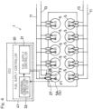
- the internal combustion engine 1 of the instant embodiment may be in the form of a multi-cylinder internal combustion engine with a plurality of cylinders 5 as shown in Fig. 4 , e.g., a ten-cylinder internal combustion engine which is illustrated in Fig. 4 .
- a multi-cylinder internal combustion engine 1 By using a multi-cylinder internal combustion engine 1, a higher power output can be achieved.
- Each of the cylinders 5 in this case has a configuration analogous to that in the embodiment described in connection with Figs. 1 to 3 . As illustrated in Fig.
- the fuel supply controller 30 executes control such that the amount of the first fuel to be delivered is decreased and the amount of the second fuel F2 to be delivered is increased, only for a particular one of the cylinders 5 for which abnormal combustion is detected by the abnormal combustion detector 33, i.e., the upper leftmost cylinder 5A in the example illustrated in the figure. It should be noted that connection lines between the cylinders 5 and the fuel amount-delivered controller 31 and abnormal combustion detector 33 are not shown in Figs. 4 and 5 , except for the cylinder 5A.
- the fuel supply controller 30 may execute the fuel amount-delivered control, at least only for a group of the cylinders 5 which include the cylinder 5A with the abnormal combustion.
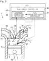
- the internal combustion engine 1 may be a prechamber internal combustion engine, as shown in another embodiment of Fig. 6 .
- the internal combustion engine 1 of the embodiment under discussion includes: a prechamber 37 located adjacent to the combustion chamber 3 and having an orifice 35 via which the prechamber 37 is in communication with the combustion chamber 3 that serves as a primary chamber; and a prechamber fuel supply line 39 via which a prechamber fuel FB is delivered to the prechamber 37.
- the prechamber 37 is located at the cylinder head 17.
- the first fuel F1 in a diluted form is delivered to the combustion chamber 3 which serves as a primary chamber, while the second fuel F2 is delivered to the intake port 9.
- the prechamber fuel FB is delivered to the prechamber 37, so that the prechamber fuel FB is ignited and burned within the prechamber 37 to form torch flame through the orifice 35 towards the combustion chamber 3 and burn the first fuel F1 within the combustion chamber 3.
- the combustion temperature can be lowered to thereby reduce the emission of NOx and suppress the occurrence of abnormal combustion.
- an improved combustion efficiency can be achieved.
- the fuel to be burned by the torch flame may also be the second fuel F2 or a mixed fuel of the first fuel F1 and the second fuel F2.
- the prechamber fuel supply line 39 is provided separate from the first fuel supply line 11 and the second fuel supply line 13.
- the fuel supply controller 30 of the internal combustion engine 1 of the instant variant executes control, upon detecting abnormal combustion, that is, in response to the abnormal combustion being detected by the abnormal combustion detector 33 and the fuel amount-delivered controller 31 receiving an abnormal combustion detection signal output from the abnormal combustion detector 33 according to the present example, such that the amount of the first fuel F1 to be delivered is decreased and the amount of the second fuel F2 to be delivered is increased.
- a third fuel F3 of a type different from the first fuel F1 or the second fuel F2 is used as the prechamber fuel FB.
- Fuels with a higher ignitability than those of the first fuel F1 and the second fuel F2, and/or diesel fuels such as, for example, light oil, heavy oil, and/or biodiesel fuels can be used as the third fuel F3.
- a fuel with a high ignitability as the third fuel, an improved ignition stability can be achieved.
- the first fuel F1, the second fuel F2, or a mixed fuel of the first fuel F1 and the second fuel F2 can also be used as the prechamber fuel FB.
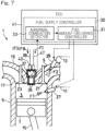
- ignition may alternatively be achieved by self-ignition of the ignition fuel FI injected into the prechamber 3 via a prechamber ignition fuel supply line 47 and a prechamber ignition fuel injector valve 49 as an alternative to the use of the ignition plug, as shown in the variant of Fig. 7 .
- control in the event of the occurrence of abnormal combustion being detected, control can be executed so that the amount of the first fuel F1 to be delivered is decreased and the amount of the second fuel F2 to be delivered is increased. In this way, the abnormal combustion can be remedied without compromising the power output of the internal combustion engines 1.
- the internal combustion engines 1 of the embodiments herein may be multi-cylinder internal combustion engines in which the cylinder comprises a plurality of cylinders 5, the first fuel supply line 11 is provided for each of the plurality of cylinders 5, and the second fuel supply line 13 is provided for each of the plurality of cylinders 5.
- the fuel supply controller 30 in this case may execute control such that the amount of the first fuel to be delivered is decreased and the amount of the second fuel F2 to be delivered is increased, at least for a minimum acceptable number of cylinders 5 including the cylinder 5A for which abnormal combustion is detected. According to this configuration, abnormal combustion can be remedied without compromising the power output of the internal combustion engines 1, including when they are designed as multi-cylinder internal combustion engines that produce a higher power output.
- the internal combustion engines 1 of the embodiments herein may further include the ignition fuel supply line 43 via which the ignition fuel FI different from the first fuel F1 or the second fuel F2 is injected to the combustion chamber 3. According to this configuration, it is possible to use the ignition fuel FI in case of emergency or when the first fuel F1 and the second fuel F2 have been depleted, in order to continue the operation of the internal combustion engines 1.
- the internal combustion engines 1 of the embodiments herein may be prechamber internal combustion engines 1 which further include: the prechamber 37 located adjacent to the combustion chamber 3 and having the orifice 35 via which the prechamber 37 is in communication with the combustion chamber 3; and the prechamber fuel supply line 39 which is provided separate from the first fuel supply line 11 and the second fuel supply line 13 and via which the prechamber fuel FB is delivered to the prechamber 37.
- the combustion temperature can be lowered to thereby reduce the emission of NOx and suppress the occurrence of abnormal combustion.
- an improved combustion efficiency can be achieved.
- the prechamber fuel FB in case of the above-described prechamber internal combustion engines 1 may comprise the third fuel F3 different from the first fuel F1 or the second fuel F2.
- the prechamber ignition fuel supply line 47 may be provided via which the ignition fuel FI different from the first fuel F1 or the second fuel F2 is injected to the prechamber 37. According to this configuration, too, the combustion temperature can be lowered to thereby reduce the emission of NOx and suppress the occurrence of abnormal combustion. In addition, an improved combustion efficiency can be achieved.
- the first fuel F1 may comprise hydrogen-containing gas. According to this configuration, the amount of carbon dioxide emitted from the internal combustion engines 1 can be lowered.
Landscapes
- Engineering & Computer Science (AREA)
- Chemical & Material Sciences (AREA)
- Combustion & Propulsion (AREA)
- Mechanical Engineering (AREA)
- General Engineering & Computer Science (AREA)
- Oil, Petroleum & Natural Gas (AREA)
- Health & Medical Sciences (AREA)
- Biomedical Technology (AREA)
- Output Control And Ontrol Of Special Type Engine (AREA)
- Combustion Methods Of Internal-Combustion Engines (AREA)
- Electrical Control Of Air Or Fuel Supplied To Internal-Combustion Engine (AREA)
Abstract
Description
- This application is based on and claims Convention priority to
Japanese patent application No. 2022-060419, filed March 31, 2022 - The present disclosure relates to an internal combustion engine in which more than one type of fuel with different reactivities can be used.
- An internal combustion engine which uses more than one type of fuel with different reactivities, e.g., hydrogen gas and hydrocarbon-based fuel, as its fuel is proposed in prior art (e.g., see Patent Document 1).
- Typically, in such an internal combustion engine, more than one type of fuel is mixed and delivered as mixed gas to a combustion chamber or an intake port.
- [Patent Document 1]
JP Laid-open Patent Publication No. 2007-278151 - If abnormal combustion such as knocking, pre-ignition, backfire, or afterfire occurs in the combustion chamber of the above-described internal combustion engine, it could only be remedied by either decreasing the amount of the mixed fuel to be delivered or interrupting the delivery of the mixed fuel, thus, making a power drop or discontinued operation of the internal combustion engine inevitable.
- Hence, one aim of the present disclosure is to overcome the above-described problem by providing an internal combustion engine in which more than one type of fuel can be used and which can remedy abnormal combustion without compromising its power output.
- To overcome the above-described problem, an internal combustion engine according to the present disclosure includes: a cylinder in which a combustion chamber is defined; a piston which reciprocates in the cylinder; an intake port via which air is introduced into the combustion chamber; a first fuel supply line via which a first fuel is delivered to the combustion chamber or the intake port; a second fuel supply line which is provided separate from the first fuel supply line and via which a second fuel having a lower reactivity than that of the first fuel is delivered to the combustion chamber or the intake port; and a fuel supply controller configured to detect abnormal combustion in the combustion chamber and execute control, in response to detecting the abnormal combustion, such that the amount of the first fuel to be delivered is decreased and the amount of the second fuel to be delivered is increased.
- Thus, the present disclosure provides an internal combustion engine in which more than one type of fuel can be used and which can remedy abnormal combustion without compromising its power output.
- Any combinations of at least two features disclosed in the claims and/or the specification and/or the drawings should also be construed as encompassed by the present disclosure. Especially, any combinations of two or more of the claims should also be construed as encompassed by the present disclosure.
- The present disclosure will be more clearly understood from the following description of preferred embodiments made with the aid of the accompanying drawings. However, the embodiments and the drawings are given merely for the purpose of illustration and explanation, and should not be used to delimit the scope of the present disclosure, which scope is to be delimited by the appended claims. In the accompanying drawings, alike numerals are assigned to and indicate alike parts throughout the different figures:
-
Fig. 1 shows a schematic, vertical cross-sectional view of the general configuration of an internal combustion engine, in accordance with an embodiment of the present disclosure; -
Fig. 2 shows a vertical cross-sectional view of the internal combustion engine ofFig. 1 , illustrating an example of how it operates in response to abnormal combustion being identified; -
Fig. 3 shows a schematic, vertical cross-sectional view of the general configuration of an internal combustion engine, in accordance with a variant of the embodiment ofFig. 1 ; -
Fig. 4 shows a schematic, block diagram of the general configuration of an internal combustion engine, in accordance with a variant of the embodiment ofFig. 1 ; -
Fig. 5 shows a vertical cross-sectional view of the internal combustion engine ofFig. 4 , illustrating an example of how it operates in response to abnormal combustion being identified; -
Fig. 6 shows a schematic, vertical cross-sectional view of the general configuration of an internal combustion engine, in accordance with another embodiment of the present disclosure; and -
Fig. 7 shows a schematic, vertical cross-sectional view of the general configuration of an internal combustion engine, in accordance with a variant of the embodiment ofFig. 6 . - While embodiments of the present disclosure will be described below in accordance with the drawings, they only represent a few of the embodiments of the present disclosure.
-
Fig. 1 depicts aninternal combustion engine 1 in accordance with an embodiment of the present disclosure. Theinternal combustion engine 1 is of a design in which two types of fuel are mixed and burned, and includes: acylinder 5 in which acombustion chamber 3 is defined; apiston 7 which reciprocates in thecylinder 5; anintake port 9 via which air is introduced into thecombustion chamber 3; a so-called direct injection-type, firstfuel supply line 11 via which a first fuel F1 is delivered to thecombustion chamber 3, and a secondfuel supply line 13 via which a second fuel F2 is delivered to theintake port 9. The secondfuel supply line 13 is provided separate from the firstfuel supply line 11. - The first fuel F1 has a relatively high reactivity. In the instant embodiment, hydrogen-containing gas is used as the first fuel F1. The term "hydrogen-containing gas" used herein encompasses a fuel partially composed of hydrogen gas as well as a fuel entirely composed of hydrogen gas. The second fuel F2 has a lower reactivity than that of the first fuel F1. In the instant embodiment, natural gas is used as the second fuel F2. Hydrogen-containing gas is only one of the non-limiting examples of the first fuel F1. For instance, normal heptane can be used for the first fuel F1. Natural gas is only one of the non-limiting examples of the second fuel F2. For instance, ammonia, alcohols such as methanol and ethanol, gasoline, heavy oil, and/or light oil can be used for the second fuel F2.
- The
piston 7 reciprocates in thecylinder 5 to drive a crankshaft (not shown) into motion through a connectingrod 15. Theinternal combustion engine 1 includes acylinder head 17 which is disposed on thecylinder 5 and which is formed with theintake port 9 and anexhaust port 19 that are open to thecombustion chamber 3. Thecombustion chamber 3 is delimited by the inner peripheral surface of thecylinder 5, the crown surface of thepiston 7, and the underside of thecylinder head 17. - The
cylinder head 17 includes anintake valve 21 which opens and closes a part of theintake port 9 which forms an opening for thecombustion chamber 3 and anexhaust valve 23 which opens and closes a part of theexhaust port 19 which forms an opening for thecombustion chamber 3. Thecylinder head 17 also includes anignition plug 25 which faces towards thecombustion chamber 3. It should be noted that, while theignition plug 25 is used to ignite the fuel(s) in thecombustion chamber 3 of theinternal combustion engine 1 of the instant embodiment, different ignition methods may alternatively be used as will be discussed later. Depending on the different ignition method used, theignition plug 25 may be omitted. - The first fuel F1 delivered via the first
fuel supply line 11 is injected into thecombustion chamber 3 through a firstfuel injector valve 27. The second fuel F2 delivered via the secondfuel supply line 13 is injected into thecombustion chamber 3 through a secondfuel injector valve 29. Theinternal combustion engine 1 of the instant embodiment can operate by only using the first fuel F1, using both of the first fuel F1 and the second fuel F2, and only using the second fuel F2. Nevertheless, it is sufficient that theinternal combustion engine 1 is operable by using both of the fuels F1 and F2, and using only the fuel F1 or the fuel F2. Examples of application of theinternal combustion engine 1 can include, in a non-limiting manner, a drive for vehicles, a drive for industrial equipment including unmanned drones, lawn mowers, and chainsaws, and power generation. - The
internal combustion engine 1 also includes afuel supply controller 30 configured to control the supply of the fuels F1 and F2. Thefuel supply controller 30 is configured to detect or identify abnormal combustion in thecombustion chamber 3 and execute control, in response to detecting the occurrence of abnormal combustion, such that the amount of the first fuel F1 to be delivered is decreased and the amount of the second fuel F2 to be delivered is increased. In the illustrated example, thefuel supply controller 30 includes a fuel amount-deliveredcontroller 31 configured to control the amounts of the fuels F1 and F2 to be delivered and anabnormal combustion detector 33 configured to detect abnormal combustion in thecombustion chamber 3. - For instance, the
abnormal combustion detector 33 in the instant embodiment is configured to detect the occurrence of abnormal combustion on the basis of sensing the combustion pressure in thecombustion chamber 3, an ion current, the vibrations of theinternal combustion engine 1, the internal pressure of theintake port 9, and/or the internal pressure of theexhaust port 19, and/or through other measures. - The combustion pressure is sensed by means of a combustion pressure sensor. The combustion pressure sensor comprises a sensor device that receives the combustion pressure on a metal diaphragm to create a compression force on an internal force sensing element which, in turn, generates a voltage signal output proportional to the combustion pressure on the basis of the piezo resistance effect of silicon. The ion current is sensed by applying a voltage across an electrode which is positioned to be situated inside a flame within the
combustion chamber 3 and determining an ion current generated by the ions present in the flame. The vibrations of theinternal combustion engine 1 are sensed by means of a knock sensor located at, for example, thecylinder 5 or a crankcase (not shown) of theinternal combustion engine 1 and/or by means of a vibration sensor bult in a given component of theinternal combustion engine 1 such as theignition plug 25 and thefuel injector valves combustion chamber 3 can be identified. - The internal pressure of the
intake port 9 and the internal pressure of theexhaust port 19 are sensed by means of a pressure sensor located in theintake port 9 and a pressure sensor located in theexhaust port 19, respectively. The sensed internal pressure of theintake port 9 can be used to detect backfire which is the propagation of a flame back into theintake port 9. The sensed internal pressure of theexhaust port 19 can be used to detect afterfire which is the phenomenon of propagation of a flame into and through theexhaust port 19. - Only one or more than one of these abnormal combustion detection measures may be employed, either alone or in combination. Further, the
abnormal combustion detector 33 may be configured to detect abnormal combustion through temperature sensing, residual oxygen concentration sensing, and/or other measures, as an alternative to or in addition to the above-described example measures. - It should be noted that the
abnormal combustion detector 33 includes, among others, a sensor device that senses a physical quantity of interest (e.g., pressure, current, and/or vibrations), a variety of circuits that perform required processing such as signal transformation and/or computation on the acquired sensing value, a memory for storing information required for the processing, a power source device such as a battery or a power circuitry through which power is fed and received from an external source, and a transmitter circuit for external transmission of output signals through a cabled or wireless connection. - As illustrated in
Fig. 2 , in response to abnormal combustion being detected by theabnormal combustion detector 33 and receiving an abnormal combustion detection signal output from theabnormal combustion detector 33, the fuel amount-deliveredcontroller 31 executes control such that the amount of the first fuel F1 to be delivered is decreased and the amount of the second fuel F2 to be delivered is increased. In particular, by way of example, the fuel amount-deliveredcontroller 31 controls the amount of the first fuel F1 to be delivered and the amount of the second fuel F2 to be delivered, by adjusting the opening ratios of the firstfuel injector valve 27 and the secondfuel injector valve 29, respectively. It should be understood that decrease in the amount of the first fuel F1 to be delivered as executed by the fuel amount-deliveredcontroller 31 herein can include interruption of the delivery of the first fuel F1. The control of the amounts of the fuels F1 and F2 to be delivered can also be conducted through a measure different from the above-described adjustment of the opening ratios of thefuel injector valves fuel supply lines - Since the first
fuel supply line 11 and the secondfuel supply line 13 are formed separate from each other in theinternal combustion engine 1 of the instant embodiment, the amounts of the first fuel F1 and the second fuel F2 to be delivered to theinternal combustion engine 1 can be easily controlled independently of each other. By relying on such a configuration, in the event of the occurrence of abnormal combustion being detected, control can be executed so that the amount of the first fuel F1 to be delivered is decreased and the amount of the second fuel F2 to be delivered is increased. In this way, the abnormal combustion can be remedied without compromising the power output of theinternal combustion engine 1. - In the instant embodiment, the
fuel supply controller 30 may execute fuel amount-delivered control differently depending on the mode of abnormal combustion detected, i.e., differently among pre-ignition, self-ignition, knocking, backfire, and afterfire. - It should be noted that the
fuel supply controller 30 includes, among others, a variety of circuits that perform processing required for the above-described control, a memory for storing information required for the processing, a power source device such as a battery or a power circuitry through which power is fed and received from an external source, a receiver circuit for external reception of input signals through a cabled or wireless connection, and a transmitter circuit for external transmission of output signals through a cabled or wireless connection. While the fuel amount-deliveredcontroller 31 and theabnormal combustion detector 33 are provided as separate pieces of hardware in the instant embodiment, they may be integrated into the same piece of hardware which forms thefuel supply controller 30. By way of example, thefuel supply controller 30 is also implemented by acontrol unit 41, such as an ECU, which is used to control the entire system to which theinternal combustion engine 1 is applied. Here, thefuel supply controller 30 may be integrated into a piece of hardware which also forms thecontrol unit 41. - It should be understood that, while the instant embodiment illustrates an example configuration in which the first fuel F1 is delivered into the
combustion chamber 3 and the second fuel F2 is delivered into theintake port 9, these fuels may be delivered to any one of thecombustion chamber 3 and theintake port 9. - While the instant embodiment also illustrates an example configuration in which the
internal combustion engine 1 includes theignition plug 25 to perform ignition within thecombustion chamber 3, a fuel serving as an ignition source (which will hereinafter be referred to as an "ignition fuel FI") may be injected into thecombustion chamber 3 via an ignitionfuel supply line 43 and an ignitionfuel injector valve 45 to allow ignition to take place through self-ignition of the ignition fuel FI as an alternative to the use of the ignition plug, as shown in a variant ofFig. 3 . Fuels with a high ignitability and/or diesel fuels such as, for example, light oil, heavy oil, and/or biodiesel fuels can be used as the ignition fuel FI. By providing the ignitionfuel supply line 43, it is possible to use the ignition fuel FI in case of emergency or when the first fuel F1 and the second fuel F2 have been depleted, in order to continue the operation of theinternal combustion engine 1. - Further, the
internal combustion engine 1 of the instant embodiment may be in the form of a multi-cylinder internal combustion engine with a plurality ofcylinders 5 as shown inFig. 4 , e.g., a ten-cylinder internal combustion engine which is illustrated inFig. 4 . By using a multi-cylinderinternal combustion engine 1, a higher power output can be achieved. Each of thecylinders 5 in this case has a configuration analogous to that in the embodiment described in connection withFigs. 1 to 3 . As illustrated inFig. 5 , thefuel supply controller 30 executes control such that the amount of the first fuel to be delivered is decreased and the amount of the second fuel F2 to be delivered is increased, only for a particular one of thecylinders 5 for which abnormal combustion is detected by theabnormal combustion detector 33, i.e., the upperleftmost cylinder 5A in the example illustrated in the figure. It should be noted that connection lines between thecylinders 5 and the fuel amount-deliveredcontroller 31 andabnormal combustion detector 33 are not shown inFigs. 4 and5 , except for thecylinder 5A. - It should be understood that, when each of different groups of the
cylinders 5, e.g., belonging to the different banks of the multi-cylinderinternal combustion engine 1, shares its own fuel supply and exhaust systems, thefuel supply controller 30 may execute the fuel amount-delivered control, at least only for a group of thecylinders 5 which include thecylinder 5A with the abnormal combustion. - It should be understood that the
internal combustion engine 1 may be a prechamber internal combustion engine, as shown in another embodiment ofFig. 6 . In addition to the features shown inFig. 1 , theinternal combustion engine 1 of the embodiment under discussion includes: aprechamber 37 located adjacent to thecombustion chamber 3 and having anorifice 35 via which theprechamber 37 is in communication with thecombustion chamber 3 that serves as a primary chamber; and a prechamberfuel supply line 39 via which a prechamber fuel FB is delivered to theprechamber 37. In the illustrated example, theprechamber 37 is located at thecylinder head 17. - In the prechamber
internal combustion engine 1, the first fuel F1 in a diluted form is delivered to thecombustion chamber 3 which serves as a primary chamber, while the second fuel F2 is delivered to theintake port 9. In addition, the prechamber fuel FB is delivered to theprechamber 37, so that the prechamber fuel FB is ignited and burned within theprechamber 37 to form torch flame through theorifice 35 towards thecombustion chamber 3 and burn the first fuel F1 within thecombustion chamber 3. By burning fuel(s) in a diluted form within thecombustion chamber 3, the combustion temperature can be lowered to thereby reduce the emission of NOx and suppress the occurrence of abnormal combustion. In addition, an improved combustion efficiency can be achieved. Note that the fuel to be burned by the torch flame may also be the second fuel F2 or a mixed fuel of the first fuel F1 and the second fuel F2. - The prechamber
fuel supply line 39 is provided separate from the firstfuel supply line 11 and the secondfuel supply line 13. Thefuel supply controller 30 of theinternal combustion engine 1 of the instant variant, too, executes control, upon detecting abnormal combustion, that is, in response to the abnormal combustion being detected by theabnormal combustion detector 33 and the fuel amount-deliveredcontroller 31 receiving an abnormal combustion detection signal output from theabnormal combustion detector 33 according to the present example, such that the amount of the first fuel F1 to be delivered is decreased and the amount of the second fuel F2 to be delivered is increased. - In the instant embodiment, a third fuel F3 of a type different from the first fuel F1 or the second fuel F2 is used as the prechamber fuel FB. Fuels with a higher ignitability than those of the first fuel F1 and the second fuel F2, and/or diesel fuels such as, for example, light oil, heavy oil, and/or biodiesel fuels can be used as the third fuel F3. By using a fuel with a high ignitability as the third fuel, an improved ignition stability can be achieved. Yet, this is only one of the non-limiting examples of the prechamber fuel FB. The first fuel F1, the second fuel F2, or a mixed fuel of the first fuel F1 and the second fuel F2 can also be used as the prechamber fuel FB.
- Furthermore, while the instant embodiment illustrates an example configuration in which the
internal combustion engine 1 includes theignition plug 25 to provide ignition within theprechamber 37, ignition may alternatively be achieved by self-ignition of the ignition fuel FI injected into theprechamber 3 via a prechamber ignitionfuel supply line 47 and a prechamber ignition fuel injector valve 49 as an alternative to the use of the ignition plug, as shown in the variant ofFig. 7 . - According to the
internal combustion engines 1 of the embodiments that are described herein thus far, in the event of the occurrence of abnormal combustion being detected, control can be executed so that the amount of the first fuel F1 to be delivered is decreased and the amount of the second fuel F2 to be delivered is increased. In this way, the abnormal combustion can be remedied without compromising the power output of theinternal combustion engines 1. - The
internal combustion engines 1 of the embodiments herein may be multi-cylinder internal combustion engines in which the cylinder comprises a plurality ofcylinders 5, the firstfuel supply line 11 is provided for each of the plurality ofcylinders 5, and the secondfuel supply line 13 is provided for each of the plurality ofcylinders 5. Thefuel supply controller 30 in this case may execute control such that the amount of the first fuel to be delivered is decreased and the amount of the second fuel F2 to be delivered is increased, at least for a minimum acceptable number ofcylinders 5 including thecylinder 5A for which abnormal combustion is detected. According to this configuration, abnormal combustion can be remedied without compromising the power output of theinternal combustion engines 1, including when they are designed as multi-cylinder internal combustion engines that produce a higher power output. - The
internal combustion engines 1 of the embodiments herein may further include the ignitionfuel supply line 43 via which the ignition fuel FI different from the first fuel F1 or the second fuel F2 is injected to thecombustion chamber 3. According to this configuration, it is possible to use the ignition fuel FI in case of emergency or when the first fuel F1 and the second fuel F2 have been depleted, in order to continue the operation of theinternal combustion engines 1. - The
internal combustion engines 1 of the embodiments herein may be prechamberinternal combustion engines 1 which further include: theprechamber 37 located adjacent to thecombustion chamber 3 and having theorifice 35 via which theprechamber 37 is in communication with thecombustion chamber 3; and the prechamberfuel supply line 39 which is provided separate from the firstfuel supply line 11 and the secondfuel supply line 13 and via which the prechamber fuel FB is delivered to theprechamber 37. According to this configuration, the combustion temperature can be lowered to thereby reduce the emission of NOx and suppress the occurrence of abnormal combustion. In addition, an improved combustion efficiency can be achieved. - The prechamber fuel FB in case of the above-described prechamber
internal combustion engines 1 may comprise the third fuel F3 different from the first fuel F1 or the second fuel F2. Also, the prechamber ignitionfuel supply line 47 may be provided via which the ignition fuel FI different from the first fuel F1 or the second fuel F2 is injected to theprechamber 37. According to this configuration, too, the combustion temperature can be lowered to thereby reduce the emission of NOx and suppress the occurrence of abnormal combustion. In addition, an improved combustion efficiency can be achieved. - In the
internal combustion engines 1 of the embodiments herein, the first fuel F1 may comprise hydrogen-containing gas. According to this configuration, the amount of carbon dioxide emitted from theinternal combustion engines 1 can be lowered. - While preferred embodiments of the present disclosure have been described thus far with reference to the drawings, various additions, modifications, or omissions can be made therein without departing from the principle of the present disclosure and, thus, are also encompassed within the scope of the present disclosure.
-
- 1
- internal combustion engine
- 3
- combustion chamber
- 5
- cylinder
- 7
- piston
- 9
- intake port
- 11
- first fuel supply line
- 13
- second fuel supply line
- 30
- fuel supply controller
- 31
- fuel amount-delivered controller
- 33
- abnormal combustion detector
- 37
- prechamber
- F1
- first fuel
- F2
- second fuel
Claims (7)
- An internal combustion engine comprising:a cylinder in which a combustion chamber is defined;a piston which reciprocates in the cylinder;an intake port via which air is introduced into the combustion chamber;a first fuel supply line via which a first fuel is delivered to the combustion chamber or the intake port;a second fuel supply line which is provided separate from the first fuel supply line and via which a second fuel having a lower reactivity than that of the first fuel is delivered to the combustion chamber or the intake port; anda fuel supply controller configured to detect abnormal combustion in the combustion chamber and execute control, in response to detecting the abnormal combustion, such that an amount of the first fuel to be delivered is decreased and an amount of the second fuel to be delivered is increased.
- The internal combustion engine as claimed in claim 1, whereinthe cylinder comprises a plurality of cylinders,the first fuel supply line is provided for each of the plurality of cylinders,the second fuel supply line is provided for each of the plurality of cylinders, andthe fuel supply controller is configured to execute control such that the amount of the first fuel to be delivered is decreased and the amount of the second fuel to be delivered is increased, at least for one of the cylinders for which the abnormal combustion is detected.
- The internal combustion engine as claimed in claim 1 or 2, further comprising an ignition fuel supply line via which an ignition fuel different from the first fuel or the second fuel is injected to the combustion chamber.
- The internal combustion engine as claimed in any one of claims 1 to 3, further comprising:a prechamber located adjacent to the combustion chamber and having an orifice via which the prechamber is in communication with the combustion chamber; anda prechamber fuel supply line which is provided separate from the first fuel supply line and the second fuel supply line and via which a prechamber fuel is delivered to the prechamber to form torch flame through the orifice.
- The internal combustion engine as claimed in claim 4, wherein the prechamber fuel comprises a third fuel different from the first fuel or the second fuel.
- The internal combustion engine as claimed in claim 4 or 5, further comprising a prechamber ignition fuel supply line via which an ignition fuel different from the first fuel or the second fuel is injected to the prechamber.
- The internal combustion engine as claimed in any one of claims 1 to 6, wherein the first fuel comprises hydrogen-containing gas.
Applications Claiming Priority (2)
| Application Number | Priority Date | Filing Date | Title |
|---|---|---|---|
| JP2022060419A JP2023151028A (en) | 2022-03-31 | 2022-03-31 | internal combustion engine |
| PCT/JP2023/008660 WO2023189299A1 (en) | 2022-03-31 | 2023-03-07 | Internal combustion engine |
Publications (2)
| Publication Number | Publication Date |
|---|---|
| EP4502355A1 true EP4502355A1 (en) | 2025-02-05 |
| EP4502355A4 EP4502355A4 (en) | 2026-04-01 |
Family
ID=88201420
Family Applications (1)
| Application Number | Title | Priority Date | Filing Date |
|---|---|---|---|
| EP23779326.0A Pending EP4502355A4 (en) | 2022-03-31 | 2023-03-07 | COMBUSTION ENGINE |
Country Status (4)
| Country | Link |
|---|---|
| EP (1) | EP4502355A4 (en) |
| JP (1) | JP2023151028A (en) |
| CN (1) | CN118974387A (en) |
| WO (1) | WO2023189299A1 (en) |
Families Citing this family (1)
| Publication number | Priority date | Publication date | Assignee | Title |
|---|---|---|---|---|
| JP7652952B1 (en) | 2024-01-31 | 2025-03-27 | ダイハツディーゼル株式会社 | Internal combustion engine |
Family Cites Families (12)
| Publication number | Priority date | Publication date | Assignee | Title |
|---|---|---|---|---|
| JPH05321670A (en) * | 1992-05-18 | 1993-12-07 | Yanmar Diesel Engine Co Ltd | Sub-chamber type lean burn gas engine |
| JP3814247B2 (en) * | 2002-12-13 | 2006-08-23 | 三菱重工業株式会社 | Premixed forced ignition gas engine |
| JP4193860B2 (en) | 2006-04-05 | 2008-12-10 | トヨタ自動車株式会社 | Internal combustion engine using hydrogen |
| JP4247842B2 (en) * | 2006-03-16 | 2009-04-02 | 三井造船株式会社 | Gas engine knocking control device |
| US8166956B2 (en) * | 2009-07-23 | 2012-05-01 | Ford Global Technologies, Llc | Engine with gaseous and/or liquid fuel injector |
| GB2479567A (en) * | 2010-04-15 | 2011-10-19 | T Baden Hardstaff Ltd | Engine system having first and second fuel type modes |
| US8904994B2 (en) * | 2010-04-26 | 2014-12-09 | Toyota Jidosha Kabushiki Kaisha | Ammonia burning internal combustion engine |
| JP2014047691A (en) * | 2012-08-30 | 2014-03-17 | Daihatsu Motor Co Ltd | Engine system |
| AT516426B1 (en) * | 2014-10-28 | 2019-08-15 | Innio Jenbacher Gmbh & Co Og | Method for controlling a dual-fuel engine |
| JP2016211438A (en) * | 2015-05-08 | 2016-12-15 | 本田技研工業株式会社 | Control device for internal combustion engine |
| AT517963B1 (en) * | 2015-12-29 | 2017-06-15 | Ge Jenbacher Gmbh & Co Og | Dual fuel engine |
| EP3336339A1 (en) * | 2016-12-15 | 2018-06-20 | Caterpillar Motoren GmbH & Co. KG | Controlling a dual-fuel internal combustion engine operated at least partly on gaseous fuel |
-
2022
- 2022-03-31 JP JP2022060419A patent/JP2023151028A/en active Pending
-
2023
- 2023-03-07 CN CN202380031442.XA patent/CN118974387A/en active Pending
- 2023-03-07 EP EP23779326.0A patent/EP4502355A4/en active Pending
- 2023-03-07 WO PCT/JP2023/008660 patent/WO2023189299A1/en not_active Ceased
Also Published As
| Publication number | Publication date |
|---|---|
| JP2023151028A (en) | 2023-10-16 |
| WO2023189299A1 (en) | 2023-10-05 |
| EP4502355A4 (en) | 2026-04-01 |
| CN118974387A (en) | 2024-11-15 |
Similar Documents
| Publication | Publication Date | Title |
|---|---|---|
| US6694960B2 (en) | Method and arrangement for determining cylinder-individual differences of a control variable in a multi-cylinder internal combustion engine | |
| EP1979607B1 (en) | Virtual fuel quality sensor | |
| EP2025903B1 (en) | Internal combustion engine | |
| US5803047A (en) | Method of control system for controlling combustion engines | |
| US20120186225A1 (en) | Methods And Apparatus To Detect And Inhibit Low-Speed Pre-Ignition In An Engine | |
| CN110469413B (en) | Method and system for engine control | |
| JP4873249B2 (en) | Control device for vehicle engine | |
| CN103443430B (en) | Pilot injection time control method during the combustion diagnosis abnormal signal of motor and device | |
| JP2007332939A (en) | Multi-fuel internal combustion engine | |
| US20190120163A1 (en) | Dual-fuel internal combustion engine | |
| US8800532B2 (en) | Method of controlling knocking in an internal combustion engine equipped with a device for controlling the opening of inlet valves | |
| JP2012172657A (en) | Auxiliary-combustion-chamber type spark-ignition gas-engine | |
| US12378937B1 (en) | Pre-ignition prevention using ion sense detection of exhaust stroke heat release for dual spark plug engines | |
| JPWO2011114508A1 (en) | Control device for internal combustion engine | |
| WO2023189299A1 (en) | Internal combustion engine | |
| JP2020094554A (en) | Control device of internal combustion engine with sub-chamber | |
| CN122029350A (en) | Control device for spark ignition type hydrogen engine and control method for spark ignition type hydrogen engine | |
| EP0313550B1 (en) | A system for controlling spark ignition in internal combustion engines | |
| JP2025083070A (en) | Ignition control device for internal combustion engine and ignition control method for internal combustion engine | |
| EP3205861A1 (en) | Method for operating multi-cylinder piston engine and multi-cylinder piston engine | |
| US10570846B2 (en) | Internal combustion engine | |
| JP2023015623A (en) | Accidental fire detection method and accidental fire detection device | |
| US20260036108A1 (en) | Combustion control for preventing knock and pre-ignition during transients in spark ignition internal combustion engines | |
| EP2534345B1 (en) | METHOD AND ARRANGEMENT FOR CONTROLLING PILOT FUEL INJECTION TO LIMIT NOx EMISSIONS OF SUPERCHARGED ENGINE | |
| JPH05321670A (en) | Sub-chamber type lean burn gas engine |
Legal Events
| Date | Code | Title | Description |
|---|---|---|---|
| STAA | Information on the status of an ep patent application or granted ep patent |
Free format text: STATUS: THE INTERNATIONAL PUBLICATION HAS BEEN MADE |
|
| PUAI | Public reference made under article 153(3) epc to a published international application that has entered the european phase |
Free format text: ORIGINAL CODE: 0009012 |
|
| STAA | Information on the status of an ep patent application or granted ep patent |
Free format text: STATUS: REQUEST FOR EXAMINATION WAS MADE |
|
| 17P | Request for examination filed |
Effective date: 20240923 |
|
| AK | Designated contracting states |
Kind code of ref document: A1 Designated state(s): AL AT BE BG CH CY CZ DE DK EE ES FI FR GB GR HR HU IE IS IT LI LT LU LV MC ME MK MT NL NO PL PT RO RS SE SI SK SM TR |
|
| DAV | Request for validation of the european patent (deleted) | ||
| DAX | Request for extension of the european patent (deleted) | ||
| A4 | Supplementary search report drawn up and despatched |
Effective date: 20260227 |
|
| RIC1 | Information provided on ipc code assigned before grant |
Ipc: F02D 19/08 20060101AFI20260223BHEP Ipc: F02B 19/12 20060101ALI20260223BHEP Ipc: F02D 41/22 20060101ALI20260223BHEP Ipc: F02D 45/00 20060101ALI20260223BHEP |