EP4502342A1 - Steam heated flange for thermal gradient control - Google Patents
Steam heated flange for thermal gradient control Download PDFInfo
- Publication number
- EP4502342A1 EP4502342A1 EP24192683.1A EP24192683A EP4502342A1 EP 4502342 A1 EP4502342 A1 EP 4502342A1 EP 24192683 A EP24192683 A EP 24192683A EP 4502342 A1 EP4502342 A1 EP 4502342A1
- Authority
- EP
- European Patent Office
- Prior art keywords
- steam
- flow
- flange
- turbine engine
- connection interface
- Prior art date
- Legal status (The legal status is an assumption and is not a legal conclusion. Google has not performed a legal analysis and makes no representation as to the accuracy of the status listed.)
- Pending
Links
Images


Classifications
-
- F—MECHANICAL ENGINEERING; LIGHTING; HEATING; WEAPONS; BLASTING
- F01—MACHINES OR ENGINES IN GENERAL; ENGINE PLANTS IN GENERAL; STEAM ENGINES
- F01D—NON-POSITIVE DISPLACEMENT MACHINES OR ENGINES, e.g. STEAM TURBINES
- F01D25/00—Component parts, details, or accessories, not provided for in, or of interest apart from, other groups
- F01D25/30—Exhaust heads, chambers, or the like
-
- F—MECHANICAL ENGINEERING; LIGHTING; HEATING; WEAPONS; BLASTING
- F01—MACHINES OR ENGINES IN GENERAL; ENGINE PLANTS IN GENERAL; STEAM ENGINES
- F01D—NON-POSITIVE DISPLACEMENT MACHINES OR ENGINES, e.g. STEAM TURBINES
- F01D25/00—Component parts, details, or accessories, not provided for in, or of interest apart from, other groups
- F01D25/24—Casings; Casing parts, e.g. diaphragms, casing fastenings
- F01D25/243—Flange connections; Bolting arrangements
-
- F—MECHANICAL ENGINEERING; LIGHTING; HEATING; WEAPONS; BLASTING
- F01—MACHINES OR ENGINES IN GENERAL; ENGINE PLANTS IN GENERAL; STEAM ENGINES
- F01D—NON-POSITIVE DISPLACEMENT MACHINES OR ENGINES, e.g. STEAM TURBINES
- F01D25/00—Component parts, details, or accessories, not provided for in, or of interest apart from, other groups
- F01D25/08—Cooling; Heating; Heat-insulation
-
- F—MECHANICAL ENGINEERING; LIGHTING; HEATING; WEAPONS; BLASTING
- F01—MACHINES OR ENGINES IN GENERAL; ENGINE PLANTS IN GENERAL; STEAM ENGINES
- F01D—NON-POSITIVE DISPLACEMENT MACHINES OR ENGINES, e.g. STEAM TURBINES
- F01D25/00—Component parts, details, or accessories, not provided for in, or of interest apart from, other groups
- F01D25/08—Cooling; Heating; Heat-insulation
- F01D25/10—Heating, e.g. warming-up before starting
-
- F—MECHANICAL ENGINEERING; LIGHTING; HEATING; WEAPONS; BLASTING
- F01—MACHINES OR ENGINES IN GENERAL; ENGINE PLANTS IN GENERAL; STEAM ENGINES
- F01D—NON-POSITIVE DISPLACEMENT MACHINES OR ENGINES, e.g. STEAM TURBINES
- F01D25/00—Component parts, details, or accessories, not provided for in, or of interest apart from, other groups
- F01D25/08—Cooling; Heating; Heat-insulation
- F01D25/14—Casings modified therefor
-
- F—MECHANICAL ENGINEERING; LIGHTING; HEATING; WEAPONS; BLASTING
- F01—MACHINES OR ENGINES IN GENERAL; ENGINE PLANTS IN GENERAL; STEAM ENGINES
- F01D—NON-POSITIVE DISPLACEMENT MACHINES OR ENGINES, e.g. STEAM TURBINES
- F01D25/00—Component parts, details, or accessories, not provided for in, or of interest apart from, other groups
- F01D25/30—Exhaust heads, chambers, or the like
- F01D25/305—Exhaust heads, chambers, or the like with fluid, e.g. liquid injection
-
- F—MECHANICAL ENGINEERING; LIGHTING; HEATING; WEAPONS; BLASTING
- F02—COMBUSTION ENGINES; HOT-GAS OR COMBUSTION-PRODUCT ENGINE PLANTS
- F02C—GAS-TURBINE PLANTS; AIR INTAKES FOR JET-PROPULSION PLANTS; CONTROLLING FUEL SUPPLY IN AIR-BREATHING JET-PROPULSION PLANTS
- F02C7/00—Features, components parts, details or accessories, not provided for in, or of interest apart form groups F02C1/00 - F02C6/00; Air intakes for jet-propulsion plants
- F02C7/12—Cooling of plants
-
- F—MECHANICAL ENGINEERING; LIGHTING; HEATING; WEAPONS; BLASTING
- F05—INDEXING SCHEMES RELATING TO ENGINES OR PUMPS IN VARIOUS SUBCLASSES OF CLASSES F01-F04
- F05D—INDEXING SCHEME FOR ASPECTS RELATING TO NON-POSITIVE-DISPLACEMENT MACHINES OR ENGINES, GAS-TURBINES OR JET-PROPULSION PLANTS
- F05D2260/00—Function
- F05D2260/20—Heat transfer, e.g. cooling
- F05D2260/213—Heat transfer, e.g. cooling by the provision of a heat exchanger within the cooling circuit
-
- F—MECHANICAL ENGINEERING; LIGHTING; HEATING; WEAPONS; BLASTING
- F05—INDEXING SCHEMES RELATING TO ENGINES OR PUMPS IN VARIOUS SUBCLASSES OF CLASSES F01-F04
- F05D—INDEXING SCHEME FOR ASPECTS RELATING TO NON-POSITIVE-DISPLACEMENT MACHINES OR ENGINES, GAS-TURBINES OR JET-PROPULSION PLANTS
- F05D2260/00—Function
- F05D2260/20—Heat transfer, e.g. cooling
- F05D2260/232—Heat transfer, e.g. cooling characterized by the cooling medium
- F05D2260/2322—Heat transfer, e.g. cooling characterized by the cooling medium steam
-
- F—MECHANICAL ENGINEERING; LIGHTING; HEATING; WEAPONS; BLASTING
- F05—INDEXING SCHEMES RELATING TO ENGINES OR PUMPS IN VARIOUS SUBCLASSES OF CLASSES F01-F04
- F05D—INDEXING SCHEME FOR ASPECTS RELATING TO NON-POSITIVE-DISPLACEMENT MACHINES OR ENGINES, GAS-TURBINES OR JET-PROPULSION PLANTS
- F05D2270/00—Control
- F05D2270/01—Purpose of the control system
- F05D2270/08—Purpose of the control system to produce clean exhaust gases
-
- F—MECHANICAL ENGINEERING; LIGHTING; HEATING; WEAPONS; BLASTING
- F05—INDEXING SCHEMES RELATING TO ENGINES OR PUMPS IN VARIOUS SUBCLASSES OF CLASSES F01-F04
- F05D—INDEXING SCHEME FOR ASPECTS RELATING TO NON-POSITIVE-DISPLACEMENT MACHINES OR ENGINES, GAS-TURBINES OR JET-PROPULSION PLANTS
- F05D2270/00—Control
- F05D2270/01—Purpose of the control system
- F05D2270/11—Purpose of the control system to prolong engine life
-
- F—MECHANICAL ENGINEERING; LIGHTING; HEATING; WEAPONS; BLASTING
- F05—INDEXING SCHEMES RELATING TO ENGINES OR PUMPS IN VARIOUS SUBCLASSES OF CLASSES F01-F04
- F05D—INDEXING SCHEME FOR ASPECTS RELATING TO NON-POSITIVE-DISPLACEMENT MACHINES OR ENGINES, GAS-TURBINES OR JET-PROPULSION PLANTS
- F05D2270/00—Control
- F05D2270/01—Purpose of the control system
- F05D2270/11—Purpose of the control system to prolong engine life
- F05D2270/112—Purpose of the control system to prolong engine life by limiting temperatures
Definitions
- the present disclosure relates generally to an aircraft propulsion system that includes a steam generation system and utilizes steam to reduce thermal gradients at bolted flanged connections between case structures.
- a turbine engine assembly includes, among other possible things, a compressor section where an inlet airflow is compressed, a combustor section where the compressed inlet airflow is mixed with fuel and ignited to generate an exhaust gas flow that is communicated through a core flow path, a turbine section through which the exhaust gas flow expands to generate a mechanical power output, an evaporator system that generates a flow of steam, a first case structure that includes a first flange, a second case structure that includes a second flange, the second flange is configured for securement to the first flange at a connection interface, and at least one steam conduit that is in thermal communication with the connection interface and configured to receive a portion of the flow of steam to heat the connection interface.
- the at least one steam conduit includes a first steam conduit that is in thermal communication with the first flange and a second steam conduit that is in thermal communication with the second flange.
- the at least one steam conduit is an integral portion of at least one of the first flange and the second flange.
- first case structure and the second case structure circumscribe portions of the combustor section and the turbine section.
- the turbine engine assembly includes a first valve that controls the portion of the flow of steam that is communicated to the at least one steam conduit.
- the turbine engine assembly includes a controller that is programmed to operate the first valve to control a temperature of the connection interface.
- the turbine engine assembly includes at least one sensor that provides information indicative of relative temperatures between an inner surface of each of the first case structure and second the second case structure.
- the steam system includes an evaporator where thermal energy from the exhaust gas flow is utilized to generate the flow of steam and at least a portion of the flow of steam is injected into the core flow path.
- the at least one steam conduit includes an outlet for the portion of the flow of steam that is in communication with an injection location for injecting exhausted steam into the core flow path.
- the turbine engine assembly includes a condenser where water is extracted from the exhaust gas flow and the evaporator is configured to receive a flow of water from the condenser.
- the turbine engine assembly further includes a fuel system that is configured to provide a non-carbon-based fuel to the combustor section.
- the turbine engine assembly further includes an intercooling system where a flow of water is utilized for cooling a portion of the compressed inlet flow.
- An aircraft propulsion system includes, among other possible things, a core engine section that defines a core flow path where an inlet airflow is compressed, mixed with fuel and ignited to generate an exhaust gas flow that is communicated through a core flow path, a condenser where water is extracted from the exhaust gas flow, an evaporator system where thermal energy from the exhaust gas flow is utilized to generate a steam flow for injection into the core flow path, a first case structure that includes a first flange, a second case structure that includes a second flange, the second flange configured for securement to the first flange at a connection interface, and at least one steam conduit that is in thermal communication with the connection interface and configured to receive a steam flow from the evaporator system to heat the connection interface.
- a control valve is configured to control the flow of steam into the at least one steam conduit.
- a controller is programmed to operate the control valve to maintain a temperature differential of the connection interface within a defined range by adjusting a flow of steam through the at least one steam conduit.
- the at least one steam conduit includes a first steam conduit that is in thermal communication with a first outer peripheral surface of the first flange and a second steam conduit that is in thermal communication with the second flange.
- the at least one steam conduit is an integral portion of at least one of the first flange and the second flange.
- first case structure and the second case structure circumscribe portions of the combustor section and the turbine section.
- a method of operating a gas turbine engine includes, among other possible things, generating an exhaust gas flow that is communicated through a core flow path, expanding the gas flow through a turbine section to generate a mechanical power output, extracting water from the exhaust gas flow in a condenser, generating a steam flow by vaporizing the heating flow of water with heat from the exhaust gas flow in the evaporator system, and controlling a temperature of a connection interface between a first flange of a first case and a second flange of a second case by adjusting a flow of steam through at least one steam conduit that is in thermal communication with the connection interface.
- the method further includes controlling the temperature of the connection interface to maintain a temperature differential between connection interface and an inner surface of the case structure that is exposed to the exhaust gas flow.
- the method further includes exhausting the steam flow from the at least one steam conduit into the core flow path.
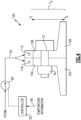
- Figure 1 schematically illustrates an example propulsion system 20 that includes a steam heated flanged connection interface 58 for controlling a thermal gradient generated by the difference in temperature between hot exhaust gases and a relatively cool ambient environment.
- the disclosed example system reduces and controls the thermal gradient to reduce thermal stresses on the connection interface 58.
- the example propulsion system 20 includes a fan section 24 and a core engine section 22.
- the core engine section 22 includes a compressor section 26, a combustor section 28 and the turbine section 30 disposed along an engine longitudinal axis A.
- the fan section 24 drives inlet airflow along a bypass flow path B, while the compressor section 26 draws air in along a core flow path C.
- the inlet airflow is compressed and communicated to the combustor section 28 where the compressed core airflow is mixed with a fuel flow 35 and ignited to generate the exhaust gas flow 82.
- the exhaust gas flow 82 expands through the turbine section 30 where energy is extracted to generate a mechanical power output utilized to drive the fan section 24 and the compressor section 26.
- an example engine architecture is disclosed by way of example, other turbine engine architectures are within the contemplation and scope of this disclosure.
- the disclosed non-limiting embodiment depicts a turbofan turbine engine, it should be understood that the concepts described herein are not limited to use with turbofans as the teachings may be applied to other types of turbine engines.
- the example engine 20 illustrates the engine components and sections disposed along a single common engine axis A, the engine sections and components may be arranged along multiple axes and have different relative orientations. Such alternate engine architectures are within the scope and contemplation of this disclosure. Additionally, the features of this disclosure may be applied to other engine configurations utilized to generate shaft power.
- a fuel system 32 including at least a fuel tank 34 and a fuel pump 36 provides the fuel flow 35 to the combustor 28.
- the example fuel system 32 is configured to provide a hydrogen-based fuel such as a liquid hydrogen (LH 2 ).
- a hydrogen-based fuel such as a liquid hydrogen (LH 2 ).
- LH 2 liquid hydrogen
- hydrogen is disclosed by way of example, other non-carbon-based fuels could be utilized and are within the contemplation of this disclosure.
- the disclosed features may also be beneficial in an engine configured to operate with traditional carbon fuels and/or biofuels, such as sustainable aviation fuel.
- An evaporator system 38 and condenser 40 are disposed downstream of the turbine section 30 and receive the exhaust gas flow 82.
- the evaporator system 38 utilizes thermal energy from the exhaust gas flow 82 to generate a steam flow 52 from a water flow 44 extracted by the condenser 40 and separated from the gas flow in a water separator 50.
- the condenser 40 cools the exhaust gas flow 82 to extract water that is separated from the gas in the water separator 50 and gathered in a tank 42.
- a pump 45 pressurizes water for communication from the water tank 42.
- a portion of the fuel flow 35 is utilized as a heat sink to cool the exhaust gas flow 82 in the condenser 40.
- a cooling ram air flow 88 is used as the cold sink.
- Other cold sink flows may be utilized to cool the exhaust gas flow 82 within the condenser 44 and are within the contemplation and scope of this disclosure.
- Water recovered with the condenser 40 may also be provided as an intercooling water flow 46 to the compressor section 26.
- the water flow 46 is injected into a location 48 within the compressor section 26 to cool the core flow and thereby increase mass flow.
- the increased mass flow improves compressor operating efficiencies.
- the example intercooling water flow 48 is shown schematically and may be injected at any location within the compressor section 26 or upstream of the combustor 28.
- the steam flow 52 from the evaporator 38 is injected into the core flow path C at or upstream of the combustor 28 and increases mass flow through the turbine section 30.
- the propulsion system 20 has an increased power output from the injected steam 52 due to an increasing mass flow through the turbine section 30 without a corresponding increase in work from the compressor section 26.
- the steam flow 52 is shown as being injected into the combustor 28, the steam flow 48 may be injected at other locations along the core flow path C and remain within the contemplation and scope of this disclosure.
- Bolted flanges that connect case structures encounter large thermal gradients due to the high temperatures within the case structures and the relatively low temperatures at outer surfaces.
- the large thermal gradients generate a significant amount of stresses due to the differences in thermal expansions on inner and outer surfaces. Differences in thermal expansion can create prying due to circumferential thermal differences that become focused as stresses at the bolted flanged connection.
- the example propulsion system 20 utilizes a portion of the steam flow to reduce thermal differences by heating portions of the connection interface 58. Raising the temperature of the connection interface 58 reduces the difference in temperature and thereby the thermal gradient.
- the example system routes a portion 54 of the steam flow into thermal contact with the connection interface 58.
- a control valve 60 is operated by a controller 62 to control a flow of the steam 54 to the connection interface 58 and maintain temperatures within a predefined range determined to limit a magnitude of the temperature gradient.
- the controller 62 receives information 90 indicative of a temperature and utilizes that information to control steam flow to the connection interface 58.
- Exhaust steam flow 56 is communicated to the combustor 28 for introduction into the core flow.
- connection interface 58 is schematically shown between a first flange 66 of a first case structure 64 and a second flange 70 of a second case structure 68.
- a bolt 72 and nut 74 secure the first flange 66 to the second flange 70.
- the bolt 72 and nut 74 may be of any configuration utilized to secure case structures together.
- the case structures 64, 68 are full round structures disposed about the engine longitudinal axis A.
- the flanges 66, 70 include a plurality of openings for a corresponding number of bolts 72 and nuts 74 that are disposed about a circumference of the case structures 64, 68.
- first case structure 64 and the second case structure 68 circumscribe portions of the combustor section 28 and the turbine section 30.
- the first case structure 64 may be a diffuser case disposed at least partially around the combustor section 28 and the second case structure 66 may be a turbine case that is disposed at least partially around a portion of the turbine section 30.
- the example connection interface 58 may be utilized at any flanged connection between case structures of a core engine 22.
- the inner surface 80 of the case structures 64, 68 is exposed to the hot exhaust gas flow 82.
- the inner surface 80 of the case structures 64, 68 is therefore of a temperature T 2 that is much higher than a temperature T 1 at an outer periphery 84, 86 of each of the flanges 66, 70 and an outer surface 85 of the case structures 64, 68.
- the temperature between T 1 and T 2 progressively cools in a direction toward the outer peripheries 84, 86.
- a first steam conduit 76 and a second steam conduit 78 are provided about the outer peripheries of the first and second flanges 66, 70.
- Steam flow 54 through the conduits 76, 78 is in thermal communication with the coolest parts of the connection interface 58 and thereby heats the connection interface 58. Heating of the outer peripheral surfaces 84, 86 reduces the temperature difference T D to provide a reduction in thermal expansion differences that in turn reduces stress.
- the steam flow 54 through the connection interface 58 is exhausted as a cooled steam flow 56 that is communicated to the combustor section 28.
- first and second steam conduits 76, 78 may be separate from the flanges 66, 70 and are attached to provide the desired thermal communication of heat energy.
- first and second steam conduits 76, 78 are disclosed by way of example, a single steam conduit that is in thermal contact with the outer peripheries of each of the flanges 66, 70 may also be utilized and is within the contemplation and scope of this disclosure.
- additional conduits may also be utilized and are within the scope and contemplation of this disclosure.
- example steam conduits 76, 78 are shown as circular in cross-section, other conduit shapes that provide for the transfer of heat energy may also be utilized and are within the contemplation of this disclosure.
- the cross-sectional shape of the conduits 76, 78 could be oval, rectangular, square or an irregular shape.
- the example steam conduits 76, 78 are formed from a material determined to transfer thermal energy into the flanges 66, 70.
- additional structures and materials may be included to encourage and direct thermal energy into the flanges 66, 70.
- the control valve 60 is operated to adjust the steam flow 54 into the conduits 76, 78 to control the temperature T 1 .
- the controller 62 adjusts the control valve 60 based on information obtained indicative of the temperature differential T D .
- the controller 62 may obtain information that is utilized to estimate the temperatures based on specific operating conditions.
- the controller 62 may also obtain information from sensors 92 and 94 disposed at locations within the case structures 64, 68 and the flanges 66, 70.
- the sensors 92, 94 may directly measure temperatures at the specific locations or provide information that is utilized to determine or estimate temperatures.
- the controller 62 is disclosed by way of example as programmed to operate the control valve 60 to adjust heating of the flanges 66, 70, the controller 62 may be programmed to operate other components to control steam flow 54 and thereby the amount of heat applied to each of the flanges 66, 70. Although a single control valve 60 is shown by way of example, additional control valves could be utilized to control steam flow individually and separately through each of the conduits 76, 78.
- controller 62 is disclosed by way of example as adjusting operation of the valve 60 based on information from the sensors 92, 94.
- the controller 62 may also utilize information indicative of engine operation, including for example, shaft speeds, pressures and temperatures at other locations in the propulsion system 20 and information indicative of ambient conditions.
- the example controller 62 is a device and system for performing necessary computing or calculation operations and may be specially constructed for this purpose.
- the controller 62 may comprise at least a general-purpose computer selectively activated or reconfigured by a computer program stored in the computer.
- the controller 62 may further be a dedicated controller, or may be a program stored on an engine or aircraft controller.
- the controller 62 may include a computer program directing operation. Such a computer program and also data required for its execution may be stored in a computer readable storage medium, such as, but is not limited to, any type of disk including floppy disks, optical disks, CD-ROMs, magnetic-optical disks, read-only memories (ROMs), random access memories (RAMS), EPROMs, EEPROMs, magnetic or optical cards, application specific integrated circuits (ASICs), or any type of media suitable for storing electronic instructions, and each coupled to a computer system bus.
- the computer referred to may include a single processor or may be architectures employing multiple processor designs for increased computing capability.
- FIG. 3 a partial axial view of the example connection interface 58 is shown with the steam conduits 76, 78 disposed on the outer peripheral surfaces 84, 86 of each of the flanges 66, 70.
- the conduits 76, 78 are arranged to provide a circumferentially directed flow.
- the steam flow 54 cools as it heats the flanges 66, 70 and is exhausted through an outlet 98 as a cooled steam flow 56.
- a single inlet 96 and a single outlet 98 are shown and disclosed by example, additional inlets and outlets could be provided about the circumference of the connection interface to provide a flow of uniform temperature.
- connection interface 100 includes a first case 102 with a first flange 104 and a second case 106 with a second flange 108.
- a first conduit 110 is integrated within the first flange 104 and a second conduit 112 is integrated within the second flange 108.
- the integrated conduits 110, 112 provide an alternate means of heating that may simplify constructions.
- Steam flow 54 is communicated to the integral conduits 110, 112 to provide for the control of the temperature differential T D and thereby a reduction in the amount of stress generated.
- the controller 62 adjusts the control valve 60 to provides the steam flow 54 based on temperature information 90.
- conduits 110 and 112 are shown as circular in cross-section, but may be of any shape. Moreover, although one conduit 110, 112 is shown in each flange 104, 108, other numbers of conduits could be utilized and remain within the contemplation and scope of this disclosure.
- example disclosed systems use thermal energy from steam generated for injection into the core flow to reduce and control the thermal gradient within a bolted flange connection interface to improve performance and durability.
Landscapes
- Engineering & Computer Science (AREA)
- Mechanical Engineering (AREA)
- General Engineering & Computer Science (AREA)
- Chemical & Material Sciences (AREA)
- Combustion & Propulsion (AREA)
- Engine Equipment That Uses Special Cycles (AREA)
- Turbine Rotor Nozzle Sealing (AREA)
Abstract
Description
- The present disclosure relates generally to an aircraft propulsion system that includes a steam generation system and utilizes steam to reduce thermal gradients at bolted flanged connections between case structures.
- Reduction and/or elimination of carbon emissions generated by aircraft operation is a stated goal of aircraft manufacturers and airline operators. Steam generation and injection into the core flow can improve propulsive efficiencies. Higher operating temperatures and pressures also improve engine efficiencies. Such increases in temperatures and pressures can increases stresses on bolted flanged connections between case structures. Thermal gradients across the bolted flanged connections are generated by the extreme temperature differences between high temperature exhaust gases within the case structure and low temperature ambient conditions at the outer surface of the case structure. Increased temperatures may further challenge such bolted flanged connections and present challenges to connection performance and durability.
- A turbine engine assembly according to one aspect of the present invention includes, among other possible things, a compressor section where an inlet airflow is compressed, a combustor section where the compressed inlet airflow is mixed with fuel and ignited to generate an exhaust gas flow that is communicated through a core flow path, a turbine section through which the exhaust gas flow expands to generate a mechanical power output, an evaporator system that generates a flow of steam, a first case structure that includes a first flange, a second case structure that includes a second flange, the second flange is configured for securement to the first flange at a connection interface, and at least one steam conduit that is in thermal communication with the connection interface and configured to receive a portion of the flow of steam to heat the connection interface.
- In a further embodiment of the foregoing turbine engine assembly, the at least one steam conduit includes a first steam conduit that is in thermal communication with the first flange and a second steam conduit that is in thermal communication with the second flange.
- In a further embodiment of any of the foregoing turbine engine assemblies, the at least one steam conduit is an integral portion of at least one of the first flange and the second flange.
- In a further embodiment of any of the foregoing turbine engine assemblies, each of the first flange and the second flange includes an outer peripheral surface and the at least one steam conduit is supported on the outer peripheral surface.
- In a further embodiment of any of the foregoing turbine engine assemblies, the first case structure and the second case structure circumscribe portions of the combustor section and the turbine section.
- In a further embodiment of any of the foregoing, the turbine engine assembly includes a first valve that controls the portion of the flow of steam that is communicated to the at least one steam conduit.
- In a further embodiment of any of the foregoing, the turbine engine assembly includes a controller that is programmed to operate the first valve to control a temperature of the connection interface.
- In a further embodiment of any of the foregoing, the turbine engine assembly includes at least one sensor that provides information indicative of relative temperatures between an inner surface of each of the first case structure and second the second case structure.
- In a further embodiment of any of the foregoing turbine engine assemblies, the steam system includes an evaporator where thermal energy from the exhaust gas flow is utilized to generate the flow of steam and at least a portion of the flow of steam is injected into the core flow path.
- In a further embodiment of any of the foregoing turbine engine assemblies, the at least one steam conduit includes an outlet for the portion of the flow of steam that is in communication with an injection location for injecting exhausted steam into the core flow path.
- In a further embodiment of any of the foregoing, the turbine engine assembly includes a condenser where water is extracted from the exhaust gas flow and the evaporator is configured to receive a flow of water from the condenser.
- In a further embodiment of any of the foregoing, the turbine engine assembly further includes a fuel system that is configured to provide a non-carbon-based fuel to the combustor section.
- In a further embodiment of any of the foregoing, the turbine engine assembly further includes an intercooling system where a flow of water is utilized for cooling a portion of the compressed inlet flow.
- An aircraft propulsion system according to another aspect of the present invention includes, among other possible things, a core engine section that defines a core flow path where an inlet airflow is compressed, mixed with fuel and ignited to generate an exhaust gas flow that is communicated through a core flow path, a condenser where water is extracted from the exhaust gas flow, an evaporator system where thermal energy from the exhaust gas flow is utilized to generate a steam flow for injection into the core flow path, a first case structure that includes a first flange, a second case structure that includes a second flange, the second flange configured for securement to the first flange at a connection interface, and at least one steam conduit that is in thermal communication with the connection interface and configured to receive a steam flow from the evaporator system to heat the connection interface. A control valve is configured to control the flow of steam into the at least one steam conduit. A controller is programmed to operate the control valve to maintain a temperature differential of the connection interface within a defined range by adjusting a flow of steam through the at least one steam conduit.
- In a further embodiment of the foregoing aircraft propulsion system, the at least one steam conduit includes a first steam conduit that is in thermal communication with a first outer peripheral surface of the first flange and a second steam conduit that is in thermal communication with the second flange.
- In a further embodiment of any of the foregoing aircraft propulsion systems, the at least one steam conduit is an integral portion of at least one of the first flange and the second flange.
- In a further embodiment of any of the foregoing aircraft propulsion systems, the first case structure and the second case structure circumscribe portions of the combustor section and the turbine section.
- A method of operating a gas turbine engine, the method, according to another aspect of the present invention includes, among other possible things, generating an exhaust gas flow that is communicated through a core flow path, expanding the gas flow through a turbine section to generate a mechanical power output, extracting water from the exhaust gas flow in a condenser, generating a steam flow by vaporizing the heating flow of water with heat from the exhaust gas flow in the evaporator system, and controlling a temperature of a connection interface between a first flange of a first case and a second flange of a second case by adjusting a flow of steam through at least one steam conduit that is in thermal communication with the connection interface.
- In a further embodiment of the foregoing, the method further includes controlling the temperature of the connection interface to maintain a temperature differential between connection interface and an inner surface of the case structure that is exposed to the exhaust gas flow.
- In a further embodiment of any of the foregoing, the method further includes exhausting the steam flow from the at least one steam conduit into the core flow path.
- Although the different examples have the specific components shown in the illustrations, embodiments of this invention are not limited to those particular combinations. It is possible to use some of the components or features from one of the examples in combination with features or components from another one of the examples.
- These and other features disclosed herein can be best understood from the following specification and drawings, the following of which is a brief description.
-
-
Figure 1 is a schematic view of an example aircraft propulsion system embodiment. -
Figure 2 is a schematic cross-sectional view of an example steam heated connection interface. -
Figure 3 is a schematic axial view of the example steam heated connection interface. -
Figure 4 is a schematic cross-sectional view of another example steam heated connection interface. -
Figure 1 schematically illustrates anexample propulsion system 20 that includes a steam heatedflanged connection interface 58 for controlling a thermal gradient generated by the difference in temperature between hot exhaust gases and a relatively cool ambient environment. The disclosed example system reduces and controls the thermal gradient to reduce thermal stresses on theconnection interface 58. - The
example propulsion system 20 includes afan section 24 and acore engine section 22. Thecore engine section 22 includes acompressor section 26, acombustor section 28 and theturbine section 30 disposed along an engine longitudinal axis A. Thefan section 24 drives inlet airflow along a bypass flow path B, while thecompressor section 26 draws air in along a core flow path C. The inlet airflow is compressed and communicated to thecombustor section 28 where the compressed core airflow is mixed with afuel flow 35 and ignited to generate theexhaust gas flow 82. Theexhaust gas flow 82 expands through theturbine section 30 where energy is extracted to generate a mechanical power output utilized to drive thefan section 24 and thecompressor section 26. - Although an example engine architecture is disclosed by way of example, other turbine engine architectures are within the contemplation and scope of this disclosure. Moreover, although the disclosed non-limiting embodiment depicts a turbofan turbine engine, it should be understood that the concepts described herein are not limited to use with turbofans as the teachings may be applied to other types of turbine engines. Moreover, although the
example engine 20 illustrates the engine components and sections disposed along a single common engine axis A, the engine sections and components may be arranged along multiple axes and have different relative orientations. Such alternate engine architectures are within the scope and contemplation of this disclosure. Additionally, the features of this disclosure may be applied to other engine configurations utilized to generate shaft power. - A
fuel system 32 including at least afuel tank 34 and afuel pump 36 provides thefuel flow 35 to thecombustor 28. Theexample fuel system 32 is configured to provide a hydrogen-based fuel such as a liquid hydrogen (LH2). Although hydrogen is disclosed by way of example, other non-carbon-based fuels could be utilized and are within the contemplation of this disclosure. Moreover, the disclosed features may also be beneficial in an engine configured to operate with traditional carbon fuels and/or biofuels, such as sustainable aviation fuel. - An
evaporator system 38 andcondenser 40 are disposed downstream of theturbine section 30 and receive theexhaust gas flow 82. Theevaporator system 38 utilizes thermal energy from theexhaust gas flow 82 to generate asteam flow 52 from awater flow 44 extracted by thecondenser 40 and separated from the gas flow in awater separator 50. Thecondenser 40 cools theexhaust gas flow 82 to extract water that is separated from the gas in thewater separator 50 and gathered in atank 42. Apump 45 pressurizes water for communication from thewater tank 42. In one disclosed example embodiment, a portion of thefuel flow 35 is utilized as a heat sink to cool theexhaust gas flow 82 in thecondenser 40. In another example embodiment, a coolingram air flow 88 is used as the cold sink. Other cold sink flows may be utilized to cool theexhaust gas flow 82 within thecondenser 44 and are within the contemplation and scope of this disclosure. - Water recovered with the
condenser 40 may also be provided as anintercooling water flow 46 to thecompressor section 26. Thewater flow 46 is injected into alocation 48 within thecompressor section 26 to cool the core flow and thereby increase mass flow. The increased mass flow improves compressor operating efficiencies. The exampleintercooling water flow 48 is shown schematically and may be injected at any location within thecompressor section 26 or upstream of thecombustor 28. - The steam flow 52 from the
evaporator 38 is injected into the core flow path C at or upstream of thecombustor 28 and increases mass flow through theturbine section 30. Thepropulsion system 20 has an increased power output from the injectedsteam 52 due to an increasing mass flow through theturbine section 30 without a corresponding increase in work from thecompressor section 26. Although thesteam flow 52 is shown as being injected into thecombustor 28, thesteam flow 48 may be injected at other locations along the core flow path C and remain within the contemplation and scope of this disclosure. - Bolted flanges that connect case structures encounter large thermal gradients due to the high temperatures within the case structures and the relatively low temperatures at outer surfaces. The large thermal gradients generate a significant amount of stresses due to the differences in thermal expansions on inner and outer surfaces. Differences in thermal expansion can create prying due to circumferential thermal differences that become focused as stresses at the bolted flanged connection. The
example propulsion system 20 utilizes a portion of the steam flow to reduce thermal differences by heating portions of theconnection interface 58. Raising the temperature of theconnection interface 58 reduces the difference in temperature and thereby the thermal gradient. - The example system routes a
portion 54 of the steam flow into thermal contact with theconnection interface 58. Acontrol valve 60 is operated by acontroller 62 to control a flow of thesteam 54 to theconnection interface 58 and maintain temperatures within a predefined range determined to limit a magnitude of the temperature gradient. Thecontroller 62 receivesinformation 90 indicative of a temperature and utilizes that information to control steam flow to theconnection interface 58.Exhaust steam flow 56 is communicated to thecombustor 28 for introduction into the core flow. - Referring to
Figure 2 with continued reference toFigure 1 , theconnection interface 58 is schematically shown between afirst flange 66 of afirst case structure 64 and asecond flange 70 of asecond case structure 68. Abolt 72 andnut 74 secure thefirst flange 66 to thesecond flange 70. Thebolt 72 andnut 74 may be of any configuration utilized to secure case structures together. As should be appreciated, thecase structures flanges bolts 72 andnuts 74 that are disposed about a circumference of thecase structures - In one disclosed example embodiment the
first case structure 64 and thesecond case structure 68 circumscribe portions of thecombustor section 28 and theturbine section 30. Thefirst case structure 64 may be a diffuser case disposed at least partially around thecombustor section 28 and thesecond case structure 66 may be a turbine case that is disposed at least partially around a portion of theturbine section 30. Although specific case structures are disclosed by way of example, theexample connection interface 58 may be utilized at any flanged connection between case structures of acore engine 22. - An
inner surface 80 of thecase structures exhaust gas flow 82. Theinner surface 80 of thecase structures outer periphery flanges outer surface 85 of thecase structures outer peripheries - A
first steam conduit 76 and asecond steam conduit 78 are provided about the outer peripheries of the first andsecond flanges Steam flow 54 through theconduits connection interface 58 and thereby heats theconnection interface 58. Heating of the outerperipheral surfaces steam flow 54 through theconnection interface 58 is exhausted as a cooledsteam flow 56 that is communicated to thecombustor section 28. - The first and
second steam conduits flanges second steam conduits flanges - Moreover, although the
example steam conduits conduits example steam conduits flanges flanges - The
control valve 60 is operated to adjust thesteam flow 54 into theconduits controller 62 adjusts thecontrol valve 60 based on information obtained indicative of the temperature differential TD. Thecontroller 62 may obtain information that is utilized to estimate the temperatures based on specific operating conditions. Thecontroller 62 may also obtain information fromsensors case structures flanges sensors - The
controller 62 is disclosed by way of example as programmed to operate thecontrol valve 60 to adjust heating of theflanges controller 62 may be programmed to operate other components to controlsteam flow 54 and thereby the amount of heat applied to each of theflanges single control valve 60 is shown by way of example, additional control valves could be utilized to control steam flow individually and separately through each of theconduits - Moreover, the
controller 62 is disclosed by way of example as adjusting operation of thevalve 60 based on information from thesensors controller 62 may also utilize information indicative of engine operation, including for example, shaft speeds, pressures and temperatures at other locations in thepropulsion system 20 and information indicative of ambient conditions. - The
example controller 62 is a device and system for performing necessary computing or calculation operations and may be specially constructed for this purpose. Alternatively, thecontroller 62 may comprise at least a general-purpose computer selectively activated or reconfigured by a computer program stored in the computer. Thecontroller 62 may further be a dedicated controller, or may be a program stored on an engine or aircraft controller. - The
controller 62 may include a computer program directing operation. Such a computer program and also data required for its execution may be stored in a computer readable storage medium, such as, but is not limited to, any type of disk including floppy disks, optical disks, CD-ROMs, magnetic-optical disks, read-only memories (ROMs), random access memories (RAMS), EPROMs, EEPROMs, magnetic or optical cards, application specific integrated circuits (ASICs), or any type of media suitable for storing electronic instructions, and each coupled to a computer system bus. Furthermore, the computer referred to may include a single processor or may be architectures employing multiple processor designs for increased computing capability. - Referring to
Figure 3 with continued reference toFigure 2 , a partial axial view of theexample connection interface 58 is shown with thesteam conduits peripheral surfaces flanges conduits steam flow 54 cools as it heats theflanges outlet 98 as a cooledsteam flow 56. Although asingle inlet 96 and asingle outlet 98 are shown and disclosed by example, additional inlets and outlets could be provided about the circumference of the connection interface to provide a flow of uniform temperature. - Referring to
Figure 4 , anotherexample connection interface 100 is schematically shown and includes afirst case 102 with afirst flange 104 and asecond case 106 with asecond flange 108. Afirst conduit 110 is integrated within thefirst flange 104 and asecond conduit 112 is integrated within thesecond flange 108. Theintegrated conduits Steam flow 54 is communicated to theintegral conduits controller 62 adjusts thecontrol valve 60 to provides thesteam flow 54 based ontemperature information 90. - The
conduits conduit flange - Accordingly, example disclosed systems use thermal energy from steam generated for injection into the core flow to reduce and control the thermal gradient within a bolted flange connection interface to improve performance and durability.
- Although an example embodiment has been disclosed, a worker of ordinary skill in this art would recognize that certain modifications would come within the scope of this disclosure. For that reason, the following claims should be studied to determine the scope and content of this disclosure.
Claims (15)
- A turbine engine assembly comprising:a compressor section (26) where an inlet airflow is compressed;a combustor section (28) where the compressed inlet airflow is mixed with fuel and ignited to generate an exhaust gas flow (82) that is communicated through a core flow path (C);a turbine section (30) through which the exhaust gas flow (82) expands to generate a mechanical power output;an evaporator system (38) configured to generate a flow of steam (52);a first case structure (64; 102) including a first flange (66; 104);a second case structure (68; 106) including a second flange (70; 108), the second flange (70; 108) configured for securement to the first flange (66; 104) at a connection interface (58; 100); andat least one steam conduit (76, 78; 110, 112) in thermal communication with the connection interface (58; 100) and configured to receive a portion of the flow of steam (52) to heat the connection interface (58; 100).
- The turbine engine assembly as recited in claim 1, wherein the at least one steam conduit (76... 112) includes a first steam conduit (76; 110) in thermal communication with the first flange (66; 104) and a second steam conduit (78; 112) in thermal communication with the second flange (70; 108).
- The turbine engine assembly as recited in claim 1 or 2, wherein the at least one steam conduit (76...112) is an integral portion of at least one of the first flange (66; 104) and the second flange (70; 108).
- The turbine engine assembly as recited in claim 1, 2 or 3, wherein each of the first flange (66; 104) and the second flange (70; 108) includes an outer peripheral surface (84, 86) and the at least one steam conduit (76... 112) is supported on the outer peripheral surface (84, 86).
- The turbine engine assembly as recited in any preceding claim, wherein the first case structure (64; 102) and the second case structure (68; 106) circumscribe portions of the combustor section (28) and the turbine section (30).
- The turbine engine assembly as recited in any preceding claim, including a first valve (60) configured to control the portion of the flow of steam communicated to the at least one steam conduit (76... 112).
- The turbine engine assembly as recited in claim 6, including a controller (62) programmed to operate the first valve (60) to control a temperature of the connection interface (58; 100).
- The turbine engine assembly as recited in any preceding claim, including at least one sensor (92, 94) providing information indicative of relative temperatures between an inner surface of each of the first case structure (64; 102) and the second case structure (68; 106).
- The turbine engine assembly as recited in any preceding claim, wherein the evaporator system (38) is configured to utilize thermal energy from the exhaust gas flow (82) to generate the flow of steam (52) and at least a portion of the flow of steam (52) is injected into the core flow path (C), optionally wherein the at least one steam conduit (76... 112) includes an outlet (98) for the portion of the flow of steam (52) that is in communication with an injection location for injecting exhausted steam into the core flow path (C).
- The turbine engine assembly as recited in any preceding claim, including a condenser (40) where water is extracted from the exhaust gas flow (82) and the evaporator system (38) is configured to receive a flow of water from the condenser (40).
- The turbine engine assembly as recited in any preceding claim, further including a fuel system (32) configured to provide a non-carbon-based fuel to the combustor section (28), and/or further including an intercooling system where a flow of water (46) is utilized for cooling a portion of the compressed inlet flow.
- An aircraft propulsion system (20) comprising:the turbine engine assembly of any of claims 1 to 5, wherein the evaporator system (38) is configured to utilize thermal energy from the exhaust gas flow (82) to generate the flow of steam (52) for injection into the core flow path (C);a condenser (40) where water is extracted from the exhaust gas flow (82);a control valve (60) configured to control the flow of steam (52) into the at least one steam conduit (76... 112); anda controller (62) programmed to operate the control valve (60) to maintain a temperature differential of the connection interface (58; 100) within a defined range by adjusting a flow of steam through the at least one steam conduit (76... 112).
- A method of operating a gas turbine engine, the method comprising:generating an exhaust gas flow (82) that is communicated through a core flow path (C);expanding the gas flow through a turbine section (30) to generate a mechanical power output;extracting water from the exhaust gas flow (82) in a condenser (40);generating a steam flow (52) by vaporizing the heating flow of water with heat from the exhaust gas flow (82) in an evaporator system (38); andcontrolling a temperature of a connection interface (58; 100) between a first flange (66; 104) of a first case structure (64; 102) and a second flange (70; 108) of a second case structure (68; 106) by adjusting a flow of steam through at least one steam conduit (76, 78; 110, 112) in thermal communication with the connection interface (58; 100).
- The method as recited in claim 13, further comprising controlling the temperature of the connection interface (58; 100) to maintain a temperature differential between connection interface (58; 100) and an inner surface of the first and/or second case structure (64... 106) that is exposed to the exhaust gas flow (82).
- The method as recited in claim 13 or 14, further comprising exhausting the steam flow (52) from the at least one steam conduit (76... 112) into the core flow path (C).
Applications Claiming Priority (1)
| Application Number | Priority Date | Filing Date | Title |
|---|---|---|---|
| US18/363,920 US12221895B1 (en) | 2023-08-02 | 2023-08-02 | Steam heated flange for thermal gradient control |
Publications (1)
| Publication Number | Publication Date |
|---|---|
| EP4502342A1 true EP4502342A1 (en) | 2025-02-05 |
Family
ID=92212585
Family Applications (1)
| Application Number | Title | Priority Date | Filing Date |
|---|---|---|---|
| EP24192683.1A Pending EP4502342A1 (en) | 2023-08-02 | 2024-08-02 | Steam heated flange for thermal gradient control |
Country Status (2)
| Country | Link |
|---|---|
| US (1) | US12221895B1 (en) |
| EP (1) | EP4502342A1 (en) |
Families Citing this family (1)
| Publication number | Priority date | Publication date | Assignee | Title |
|---|---|---|---|---|
| US12338769B2 (en) * | 2023-09-08 | 2025-06-24 | General Electric Company | Turbine engine including a steam system |
Citations (4)
| Publication number | Priority date | Publication date | Assignee | Title |
|---|---|---|---|---|
| US20070214766A1 (en) * | 2006-03-16 | 2007-09-20 | Mitsuru Obana | Gas turbine engine |
| WO2016068858A1 (en) * | 2014-10-28 | 2016-05-06 | Siemens Aktiengesellschaft | Flange cooling system for hot gas path plenums in a turbine engine |
| US20170254225A1 (en) * | 2016-03-07 | 2017-09-07 | Mitsubishi Hitachi Power Systems, Ltd. | Steam Turbine Plant |
| US10337357B2 (en) * | 2017-01-31 | 2019-07-02 | General Electric Company | Steam turbine preheating system with a steam generator |
Family Cites Families (10)
| Publication number | Priority date | Publication date | Assignee | Title |
|---|---|---|---|---|
| JP4015284B2 (en) | 1998-06-09 | 2007-11-28 | 三菱重工業株式会社 | Flange cooling structure of steam turbine casing |
| DE19850470A1 (en) | 1998-11-02 | 2000-02-03 | Siemens Ag | Turbine housing e.g. with internal cooling of part-joined zone sealing bolts of steam turbine |
| US7037065B2 (en) | 2002-03-20 | 2006-05-02 | Alstom Technology Ltd | Flange bolt for turbines |
| US8240988B2 (en) | 2008-03-26 | 2012-08-14 | Siemens Energy, Inc. | Fastener assembly with cyclone cooling |
| US8899051B2 (en) * | 2010-12-30 | 2014-12-02 | Rolls-Royce Corporation | Gas turbine engine flange assembly including flow circuit |
| US20120228862A1 (en) | 2011-03-11 | 2012-09-13 | General Electric Company | Temperature reducing flange for steam turbine inlets |
| US9127558B2 (en) * | 2012-08-01 | 2015-09-08 | General Electric Company | Turbomachine including horizontal joint heating and method of controlling tip clearance in a gas turbomachine |
| EP2824287B1 (en) * | 2013-07-08 | 2020-05-13 | Ansaldo Energia IP UK Limited | Pressure casing of a turbomachine |
| US10774741B2 (en) * | 2016-01-26 | 2020-09-15 | General Electric Company | Hybrid propulsion system for a gas turbine engine including a fuel cell |
| DE102018208026A1 (en) * | 2018-05-22 | 2019-11-28 | MTU Aero Engines AG | An exhaust treatment device, aircraft propulsion system, and method of treating an exhaust flow |
-
2023
- 2023-08-02 US US18/363,920 patent/US12221895B1/en active Active
-
2024
- 2024-08-02 EP EP24192683.1A patent/EP4502342A1/en active Pending
Patent Citations (4)
| Publication number | Priority date | Publication date | Assignee | Title |
|---|---|---|---|---|
| US20070214766A1 (en) * | 2006-03-16 | 2007-09-20 | Mitsuru Obana | Gas turbine engine |
| WO2016068858A1 (en) * | 2014-10-28 | 2016-05-06 | Siemens Aktiengesellschaft | Flange cooling system for hot gas path plenums in a turbine engine |
| US20170254225A1 (en) * | 2016-03-07 | 2017-09-07 | Mitsubishi Hitachi Power Systems, Ltd. | Steam Turbine Plant |
| US10337357B2 (en) * | 2017-01-31 | 2019-07-02 | General Electric Company | Steam turbine preheating system with a steam generator |
Also Published As
| Publication number | Publication date |
|---|---|
| US12221895B1 (en) | 2025-02-11 |
| US20250043700A1 (en) | 2025-02-06 |
Similar Documents
| Publication | Publication Date | Title |
|---|---|---|
| CN114278402B (en) | Heat engine with cooled cooling air heat exchanger system | |
| US11143106B2 (en) | Combustion section heat transfer system for a propulsion system | |
| CN110529256B (en) | Air cycle assembly for a gas turbine engine assembly | |
| EP4455466A1 (en) | Aftercooler exhaust duct protection | |
| JP5036496B2 (en) | Leaching gap control turbine | |
| JP6401581B2 (en) | Surface cooler support mechanism | |
| US20170159568A1 (en) | Intercooling system and method for a gas turbine engine | |
| US20170114721A1 (en) | Method and system for managing heat flow in an engine | |
| EP2375005B1 (en) | Method for controlling turbine blade tip seal clearance | |
| EP2236750B1 (en) | An impingement cooling arrangement for a gas turbine engine | |
| EP3091196B1 (en) | System and method for improving exhaust energy recovery | |
| US12215622B1 (en) | Partial exhaust condensation intercooling | |
| JP2009052552A (en) | Turbine diffuser seal method, system and apparatus | |
| EP4455465B1 (en) | Offset core with side ejector nacelle nozzles | |
| US12221895B1 (en) | Steam heated flange for thermal gradient control | |
| CN115680791B (en) | Gap control components | |
| EP4556697A2 (en) | Fluidic compressor inlet guide vanes | |
| EP4474629A1 (en) | Water cooled exhaust duct | |
| EP4477845A1 (en) | Water active turbine clearance control | |
| US20230117984A1 (en) | Heat engine with heat exchanger | |
| US12331684B2 (en) | Strut microtube counterflow evaporator | |
| US12510023B1 (en) | Fan case mounted evaporator for aircraft turbine engine | |
| US10087767B2 (en) | Pre-diffuser with multiple radii | |
| US12163470B2 (en) | Heat exchanger(s) for recovering water and/or heat energy from turbine engine combustion products | |
| RU2594091C1 (en) | Engine of hypersonic aircraft |
Legal Events
| Date | Code | Title | Description |
|---|---|---|---|
| PUAI | Public reference made under article 153(3) epc to a published international application that has entered the european phase |
Free format text: ORIGINAL CODE: 0009012 |
|
| STAA | Information on the status of an ep patent application or granted ep patent |
Free format text: STATUS: THE APPLICATION HAS BEEN PUBLISHED |
|
| AK | Designated contracting states |
Kind code of ref document: A1 Designated state(s): AL AT BE BG CH CY CZ DE DK EE ES FI FR GB GR HR HU IE IS IT LI LT LU LV MC ME MK MT NL NO PL PT RO RS SE SI SK SM TR |
|
| STAA | Information on the status of an ep patent application or granted ep patent |
Free format text: STATUS: REQUEST FOR EXAMINATION WAS MADE |
|
| 17P | Request for examination filed |
Effective date: 20250728 |
|
| RIC1 | Information provided on ipc code assigned before grant |
Ipc: F01D 25/08 20060101AFI20251119BHEP Ipc: F01D 25/30 20060101ALI20251119BHEP |
|
| GRAP | Despatch of communication of intention to grant a patent |
Free format text: ORIGINAL CODE: EPIDOSNIGR1 |
|
| STAA | Information on the status of an ep patent application or granted ep patent |
Free format text: STATUS: GRANT OF PATENT IS INTENDED |
|
| INTG | Intention to grant announced |
Effective date: 20260120 |