EP4502299A1 - Control device, control method, and work machine - Google Patents
Control device, control method, and work machine Download PDFInfo
- Publication number
- EP4502299A1 EP4502299A1 EP23857096.4A EP23857096A EP4502299A1 EP 4502299 A1 EP4502299 A1 EP 4502299A1 EP 23857096 A EP23857096 A EP 23857096A EP 4502299 A1 EP4502299 A1 EP 4502299A1
- Authority
- EP
- European Patent Office
- Prior art keywords
- detection signal
- tilt amount
- neutral position
- case
- output
- Prior art date
- Legal status (The legal status is an assumption and is not a legal conclusion. Google has not performed a legal analysis and makes no representation as to the accuracy of the status listed.)
- Pending
Links
Images




Classifications
-
- E—FIXED CONSTRUCTIONS
- E02—HYDRAULIC ENGINEERING; FOUNDATIONS; SOIL SHIFTING
- E02F—DREDGING; SOIL-SHIFTING
- E02F9/00—Component parts of dredgers or soil-shifting machines, not restricted to one of the kinds covered by groups E02F3/00 - E02F7/00
- E02F9/20—Drives; Control devices
- E02F9/22—Hydraulic or pneumatic drives
- E02F9/2203—Arrangements for controlling the attitude of actuators, e.g. speed, floating function
-
- E—FIXED CONSTRUCTIONS
- E02—HYDRAULIC ENGINEERING; FOUNDATIONS; SOIL SHIFTING
- E02F—DREDGING; SOIL-SHIFTING
- E02F9/00—Component parts of dredgers or soil-shifting machines, not restricted to one of the kinds covered by groups E02F3/00 - E02F7/00
- E02F9/20—Drives; Control devices
- E02F9/2004—Control mechanisms, e.g. control levers
-
- E—FIXED CONSTRUCTIONS
- E02—HYDRAULIC ENGINEERING; FOUNDATIONS; SOIL SHIFTING
- E02F—DREDGING; SOIL-SHIFTING
- E02F9/00—Component parts of dredgers or soil-shifting machines, not restricted to one of the kinds covered by groups E02F3/00 - E02F7/00
- E02F9/20—Drives; Control devices
- E02F9/2025—Particular purposes of control systems not otherwise provided for
- E02F9/2033—Limiting the movement of frames or implements, e.g. to avoid collision between implements and the cabin
-
- E—FIXED CONSTRUCTIONS
- E02—HYDRAULIC ENGINEERING; FOUNDATIONS; SOIL SHIFTING
- E02F—DREDGING; SOIL-SHIFTING
- E02F9/00—Component parts of dredgers or soil-shifting machines, not restricted to one of the kinds covered by groups E02F3/00 - E02F7/00
- E02F9/20—Drives; Control devices
- E02F9/22—Hydraulic or pneumatic drives
- E02F9/2221—Control of flow rate; Load sensing arrangements
- E02F9/2225—Control of flow rate; Load sensing arrangements using pressure-compensating valves
- E02F9/2228—Control of flow rate; Load sensing arrangements using pressure-compensating valves including an electronic controller
-
- E—FIXED CONSTRUCTIONS
- E02—HYDRAULIC ENGINEERING; FOUNDATIONS; SOIL SHIFTING
- E02F—DREDGING; SOIL-SHIFTING
- E02F9/00—Component parts of dredgers or soil-shifting machines, not restricted to one of the kinds covered by groups E02F3/00 - E02F7/00
- E02F9/26—Indicating devices
-
- E—FIXED CONSTRUCTIONS
- E02—HYDRAULIC ENGINEERING; FOUNDATIONS; SOIL SHIFTING
- E02F—DREDGING; SOIL-SHIFTING
- E02F9/00—Component parts of dredgers or soil-shifting machines, not restricted to one of the kinds covered by groups E02F3/00 - E02F7/00
- E02F9/26—Indicating devices
- E02F9/267—Diagnosing or detecting failure of vehicles
- E02F9/268—Diagnosing or detecting failure of vehicles with failure correction follow-up actions
Definitions
- the present disclosure relates to a control device, a control method, and a work machine.
- Patent Document 1 discloses a control device that detects a tilt angle of an operation lever of work equipment by two detection units, compares the detected tilt angles, determines whether or not there is an abnormality on the basis of a comparison result, and controls the work equipment on the basis of a detection result of a tilt angle that is smaller in a case where there is the abnormality.
- the two detection units disclosed in Patent Document 1 have characteristics in which one detection unit decreases a voltage of a detection signal as an angle increases and the other detection unit increases the voltage of the detection signal as the angle increases.
- the control device determines whether or not there is an abnormality by comparing a total value of the two detection signals with a normal value.
- Patent Document 1 Japanese Unexamined Patent Application, First Publication No. 2006-328759
- the control device disclosed in Patent Document 1 controls the work equipment based on a detection result of the smaller angle between the detection results of the two detection units. Therefore, for example, in a case where one detection unit is normal, there is a problem that the work equipment may not be operated in a case where an abnormality occurs such that only a signal corresponding to a neutral position can be output in an abnormal detection unit.
- the present disclosure has been made in view of the above circumstances, and an object of the present disclosure is to provide a control device, a control method, and a work machine capable of appropriately dealing with a case where an abnormality occurs in the detection of a tilt amount of an operation lever of the work equipment.
- a control device of a work machine including work equipment, the control device including: an acquisition unit configured to acquire a first detection signal output according to a tilt amount of an operation lever by a first tilt amount sensor configured to detect the tilt amount of the operation lever of the work equipment tilted from a neutral position in a first direction or a second direction opposite to the first direction, and a second detection signal output according to the tilt amount by a second tilt amount sensor configured to detect the tilt amount; and a control unit configured to determine whether or not the first detection signal and the second detection signal are a value corresponding to the neutral position at a time of start of the work machine, generate and output a predetermined control signal for controlling the work equipment based on the first detection signal in a case where both of the first detection signal and the second detection signal are the value corresponding to the neutral position, and in a case where any one of the first detection signal or the second detection signal is not the value corresponding to the neutral position, generate and output the control signal based on the other of the first detection
- a control method of a work machine including work equipment including: a step of acquiring a first detection signal output according to a tilt amount of an operation lever by a first tilt amount sensor configured to detect the tilt amount of the operation lever of the work equipment tilted from a neutral position in a first direction or a second direction opposite to the first direction, and a second detection signal output according to the tilt amount by a second tilt amount sensor configured to detect the tilt amount; and a step of determining whether or not the first detection signal and the second detection signal are a value corresponding to the neutral position at a time of start of the work machine, generating and outputting a predetermined control signal for controlling the work equipment based on the first detection signal in a case where both of the first detection signal and the second detection signal are the value corresponding to the neutral position, and in a case where any one of the first detection signal or the second detection signal is not the value corresponding to the neutral position, generating and outputting the control signal based on the other of
- a work machine including: a work equipment; an acquisition unit configured to acquire a first detection signal output according to a tilt amount of an operation lever by a first tilt amount sensor configured to detect the tilt amount of the operation lever of the work equipment tilted from a neutral position in a first direction or a second direction opposite to the first direction, and a second detection signal output according to the tilt amount by a second tilt amount sensor configured to detect the tilt amount; and a control unit configured to determine whether or not the first detection signal and the second detection signal are a value corresponding to the neutral position at a time of start of the work machine, generate and output a predetermined control signal for controlling the work equipment based on the first detection signal in a case where both of the first detection signal and the second detection signal are the value corresponding to the neutral position, and in a case where any one of the first detection signal or the second detection signal is not the value corresponding to the neutral position, generate and output the control signal based on the other of the first detection signal or the second detection signal,
- control device the control method, and the work machine of the present disclosure, it is possible to appropriately cope with a case where an abnormality occurs in detection of a tilt amount of an operation lever of work equipment.
- a local coordinate system is set in a work machine 1, and a positional relationship of each of units will be described with reference to the local coordinate system.
- a first axis extending in a right-left direction (vehicle width direction) of the work machine 1 will be defined as an X-axis
- a second axis extending in a front-rear direction of the work machine 1 will be defined as a Y-axis
- a third axis extending in an up-down direction of the work machine 1 will be defined as a Z-axis.
- the X-axis and the Y-axis are orthogonal to each other.
- the Y-axis and the Z-axis are orthogonal to each other.
- a +X-direction is the right direction, and a -X-direction is the left direction.
- a +Y-direction is the front direction, and a -Y-direction is the rear direction.
- a +Z-direction is the up direction, and a -Z-direction is the down direction.
- FIG. 1 is a side view showing the work machine 1 according to the present embodiment.
- the work machine 1 according to the present embodiment is a wheel loader.
- the work machine 1 will be referred to as a wheel loader 1 as appropriate.
- the wheel loader 1 has a vehicle body 2, a cab 3, a traveling device 4, and work equipment 10.
- the wheel loader 1 travels on a work place by using the traveling device 4.
- the wheel loader 1 carries out work by using the work equipment 10.
- the wheel loader 1 can use the work equipment 10 to carry out the work, such as excavation work, loading work, transport work, and snow removal work.
- the cab 3 is supported by the vehicle body 2. Inside the cab 3, a driver's seat 31 on which an operator sits, an operation device 32 to be described later, a display and input unit 35, and an output unit 36 are disposed.
- the traveling device 4 has rotatable wheels 5.
- the wheels 5 support the vehicle body 2.
- the wheel loader 1 can travel on a road surface (or ground) RS by the traveling device 4. It should be noted that FIG. 1 shows only a front wheel 5F and a rear wheel 5R on a left side.
- the work equipment 10 is supported by vehicle body 2.
- the work equipment 10 is configured by a bucket 12 as an example of a work tool, and a movable support section 17 that changes a position and a posture of the bucket 12.
- the movable support section 17 includes a boom 11, a boom cylinder 13, a bucket cylinder 14, a bell crank 15, and a link 16.
- the boom 11 is rotatably supported with respect to the vehicle body 2, and moves in the up-down direction according to expansion and contraction of the boom cylinder 13.
- the boom cylinder 13 is an actuator that generates power for moving the boom 11, and has one end portion connected to the vehicle body 2 and the other end portion connected to the boom 11.
- the boom cylinder 13 contracts and extends.
- the boom cylinder 13 is, for example, a hydraulic cylinder.
- the bucket 12 has bucket teeth 12T and is a work tool for performing excavation of the object to be excavated such as earth or loading thereof.
- the bucket 12 is rotatably connected to the boom 11, and is rotatably connected to one end portion of the link 16.
- the other end portion of the link 16 is rotatably connected to one end portion of the bell crank 15.
- the bell crank 15 has a central portion connected to the boom 11 to be rotationally movable, and the other end portion rotatably connected to one end portion of the bucket cylinder 14.
- the other end portion of the bucket cylinder 14 is rotatably connected to the vehicle body 2.
- the bucket 12 is operated by power generated by the bucket cylinder 14.
- the bucket cylinder 14 is an actuator that generates power for moving the bucket 12.
- the bucket cylinder 14 is contracted and extended. As a result, the bucket 12 swings.
- the bucket cylinder 14 is, for example, a hydraulic cylinder.
- the bucket teeth 12T has a shape of chevron teeth, flat teeth, or the like, and is attached to an end portion of the bucket 12 to be replaceable.
- FIG. 2 is a block diagram showing a configuration example of the control system of the wheel loader 1 according to the present embodiment.
- the wheel loader 1 includes a power source 201, a power take off (PTO) 202, a hydraulic pump 203, a control valve 200, an operation device 32, a display and input unit 35, an output unit 36, and a controller 100.
- PTO power take off
- the power source 201 generates a driving force for operating the work machine.
- An internal combustion engine and an electric motor are exemplary examples of the power source.
- the PTO 202 transmits at least a part of the driving force of the power source 201 to the hydraulic pump 203.
- the PTO 202 distributes the driving force of the power source 201 to the traveling device 4 and the hydraulic pump 203.
- the hydraulic pump 203 is driven by the power source 201, and discharges a hydraulic oil. At least a part of the hydraulic oil discharged from the hydraulic pump 203 is supplied to each of the boom cylinder 13 and the bucket cylinder 14 via the control valve 200.
- the control valve 200 receives a predetermined control signal from the controller 100 and controls the flow rate, the pressure, and the direction of the hydraulic oil supplied to each of the boom cylinder 13 and the bucket cylinder 14 from the hydraulic pump 203.
- the work equipment 10 is operated by the hydraulic oil from the hydraulic pump 203.
- the operation device 32 is disposed inside the cab 3.
- the operation device 32 is operated by the operator.
- the operator operates the operation device 32 to adjust a traveling direction and a traveling speed of the wheel loader 1, switches between forward and rearward movement, and operates the work equipment 10.
- the operation device 32 includes, for example, a steering, a shift lever, an accelerator pedal, a brake pedal, a boom operation lever 33, and a bucket operation lever 34.
- the boom operation lever 33 is an operation lever for operating the posture of the boom 11.
- the boom operation lever 33 includes a main angle sensor 331 and a sub angle sensor 332, and outputs two detection signals indicating the tilt amount of the operation lever.
- the bucket operation lever 34 is an operation lever for operating the posture of the bucket 12.
- the bucket operation lever 34 includes a main angle sensor 341 and a sub angle sensor 342, and outputs two detection signals indicating the tilt amount of the operation lever.
- the boom operation lever 33 and the bucket operation lever 34 are referred to as operation levers.
- the main angle sensor 331, the sub angle sensor 332, the main angle sensor 341, and the sub angle sensor 342, the main angle sensor 331, the sub angle sensor 332, the main angle sensor 341, and the sub angle sensor 342 are referred to as an angle sensor.
- the main angle sensor 331 and the main angle sensor 341 are collectively referred to, the main angle sensor 331 and the main angle sensor 341 are referred to as a main angle sensor.
- the sub angle sensor 332 and the sub angle sensor 342 are collectively referred to, the sub angle sensor 332 and the sub angle sensor 342 are referred to as a sub angle sensor.
- the angle sensor detects a tilt amount of the operation lever and outputs a detection signal indicating a detection result by an analog voltage value.
- the tilt amount can be represented by a value corresponding to, for example, the tilt angle, a movement amount of a grip portion, and the like.
- the angle sensor can be configured by, for example, a combination of a variable resistor (potentiometer) and a signal processing circuit, a combination of a hall element and a signal processing circuit, or the like.
- each detection signal is set such that a total value of a voltage value of the detection signal of the main angle sensor and a voltage value of the detection signal of the sub angle sensor is a constant value.
- the main angle sensor may be simply referred to as a main
- the sub angle sensor may be simply referred to as a sub.
- the display and input unit 35 is configured by a combination of an input device and a display device, an input display device, such as a touch panel, and the like.
- the operator inputs, for example, a set value or the like in the control of the work equipment 10 using the display and input unit 35.
- the output unit 36 includes a display device, an output device for a synthetic voice, an alarm sound, or a notification sound, a display lamp such as a warning lamp, or the like, and outputs predetermined information.
- the main angle sensor is an example of a first tilt amount sensor according to the present disclosure.
- the sub angle sensor is an example of a second tilt amount sensor according to the present disclosure.
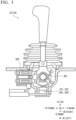
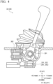
- FIGS. 3 and 4 are cross-sectional views showing the boom operation lever 33 and the bucket operation lever 34 according to the present embodiment.
- the boom operation lever 33 and the bucket operation lever 34 may have the same configuration, and hereinafter, the boom operation lever 33 will be described as an example.
- FIG. 3 shows a case where a tilt position of the boom operation lever 33 is a neutral position
- FIG. 4 shows a case where the tilt position of the boom operation lever 33 is a position reaching a stroke end in a rear direction.
- the boom operation lever 33 is also tilted in the front direction in the same manner.
- the boom operation lever 33 has a mechanism that automatically returns the position of the operation lever to the neutral position in a state where a certain or more operation force is not applied to the operation lever.
- the angle sensor is provided below the operation lever and detects the tilt amount of the operation lever.
- a spring 301 is provided at a tilting center of the operation lever. The spring 301 has a function of automatically returning the position of the operation lever to the neutral position.
- a detent solenoid 302 is provided below the operation lever. The detent solenoid 302 has a function of holding the operation lever at a position where the operation lever is most tilted even in a case where the hand is released from the operation lever when the operation lever is most tilted in a case where the current flows to the detent solenoid 302.
- the operation lever according to the present embodiment is the operation lever of the work equipment 10 that is tilted from the neutral position in the first direction (for example, the front direction) or the second direction (for example, the rear direction) opposite to the first direction.
- FIG. 5 is an output characteristic diagram of the angle sensor according to the embodiment of the present disclosure.
- a horizontal axis is the output voltage
- a vertical axis is the operation lever stroke.
- the operation lever stroke is represented by a percentage in a case where the stroke end is set to "1".
- the neutral position is set to "0%”, and for example, a case where the operation lever is tilted forward is represented by a negative value, and a case where the operation lever is tilted backward is represented by a positive value.
- the positive and negative directions may be reversed.
- a voltage value V1 is, for example, "0 V”
- a voltage value V5 is, for example, "5 V”.
- a range of a signal voltage in the controller 100 is a direct current of 0 to 5 V.
- a voltage value V2 is a determination voltage for a ground failure
- a voltage value V4 is a determination voltage for a power supply failure. In a case where the voltage of the detection signal output by the angle sensor is V2 or less, it can be determined that the ground failure occurs. In a case where the voltage of the detection signal output by the angle sensor is V4 or more, it can be determined that the power supply failure occurs.
- a range of the detection signal of the angle sensor is smaller than a range of the voltage value V2 to the voltage value V4.
- the voltage value V3 is a voltage corresponding to the neutral position, and is, for example, "2.5 V".
- the total value of the voltage value Vm of the detection signal of the main angle sensor and the voltage value Vs of the detection signal of the sub angle sensor is constant, for example, "5 V".
- a solid line indicates a voltage value Vm of the detection signal of the main angle sensor
- a one-dot chain line indicates a voltage value Vs of the detection signal of the sub angle sensor.
- Output characteristics indicated by a two-dot chain line are an example in a case where the output characteristics indicated by the solid line fall due to some kind of problem. For example, in a case where the voltage value of the detection signal of the main angle sensor is decreased to Vm', the sum of Vm' and Vs is less than 5 V
- the controller 100 is configured by using, for example, a field programmable gate array (FPGA) or a microcomputer having a processor, a main storage device, an auxiliary storage device, an input/output device, and the like.
- the controller 100 includes an acquisition unit 101 and a control unit 102 as a functional configuration composed of a combination of hardware, software such as a program, and the like.
- the controller 100 according to the present embodiment drives and controls the boom cylinder 13 and the bucket cylinder 14 by controlling the control valve 200 according to an operation of the operation device 32 and the like.
- the controller 100 is an example of a control device according to the present disclosure.
- the acquisition unit 101 repeatedly acquires each detection signal (first detection signal) output by the main angle sensor according to the tilt amount of the operation lever and each detection signal (second detection signal) output by the sub angle sensor according to the tilt amount of the operation lever, for example, at a predetermined cycle (for example, a cycle of several milliseconds to several hundreds of milliseconds).
- the control unit 102 determines whether or not each detection signal is normal or abnormal based on the detection signal of the main angle sensor and the detection signal of the sub angle sensor, and selects which detection signal of the angle sensor is to be used to control the control valve 200 when the detection signal is abnormal. There are the following two types of determination of whether or not there is an abnormality performed by the control unit 102. One is determination of whether or not each detection signal is a value indicating that the operation lever is in the neutral position, on the premise that the operation lever is not operated at the time of turning on the key (at the time of starting the wheel loader 1) of the wheel loader 1. This determination is referred to as a neutral determination.
- the time when the key is turned on is a time shorter than a time normally required from turning on the key to starting the operation of the operation lever, and is, for example, a time of several seconds to several tens of seconds from turning on the key.
- Another determination is whether or not the total value of the voltage values of the main and sub detection signals is a predetermined constant value. This determination is referred to as a sum determination or an error determination. The sum determination is not limited to the start, and can be performed even during the operation of the operation lever.
- the control unit 102 determines whether or not the detection signal (first detection signal) of the main angle sensor and the detection signal (second detection signal) of the sub angle sensor are a value corresponding to the neutral position, and in a case where both of the first detection signal and the second detection signal are values corresponding to the neutral position, the control unit 102 generates and outputs a predetermined control signal for controlling the work equipment 10 based on the first detection signal.
- the control unit 102 in a case where any one of the first detection signal or the second detection signal does not have the value corresponding to the neutral position, the control unit 102 generates and outputs the control signal based on the other of the first detection signal or the second detection signal, and outputs predetermined information corresponding to a case where one of the first detection signal or the second detection signal from the output unit 36 does not have the value corresponding to the neutral position.
- the value corresponding to the neutral position is a voltage value within V3 ⁇ ⁇ .
- ⁇ is a voltage value in an allowable range of the determination.
- the output of the predetermined information is, for example, display of an error code representing a case where the value does not correspond to the neutral position, notification that the abnormality is detected by a synthetic voice or an electronic sound, lighting or blinking of a predetermined display lamp, and the like.
- the output of the predetermined information is also referred to as error report.
- the control unit 102 in a case where any one of the first detection signal or the second detection signal does not have a value corresponding to the neutral position, the control unit 102 generates and outputs the control signal on the basis of the other of the first detection signal or the second detection signal after limiting the function of the work equipment 10.
- the restriction of the function of the work equipment 10 is a restriction of an action or an operation of the work equipment 10, and is, for example, a restriction of an operation speed of the work equipment 10 to a value lower than a normal value (for example, a normal value of several to several tens of %).
- the control unit 102 determines whether or not the total value of the first detection signal and the second detection signal is a certain value, and in a case where the total value is not the certain value, the control unit 102 generates and outputs a control signal to stop the operation of the predetermined actuator of the work equipment 10.
- the certain value is a voltage value within a range of 2 times the voltage value V3 ⁇ ⁇ described with reference to FIG. 5 .
- ⁇ is a voltage value in an allowable range of the determination.
- the control unit 102 repeatedly determines whether or not the detection signal (first detection signal) of the main angle sensor and the detection signal (second detection signal) of the sub angle sensor correspond to the neutral position from a time of the key-on for a predetermined time.
- the predetermined time can be, for example, about several seconds to several tens of seconds.
- the control unit 102 outputs an alarm of that fact from the output unit 36.
- the control unit 102 stops the output of the alarm, and generates and outputs a control signal for controlling the work equipment 10 based on the first detection signal.
- the output of the alarm is, for example, display of an error code indicating that the operation lever is not in the neutral position, notification that the operation lever is not in the neutral position by synthetic voice or electronic sound, lighting or blinking of a predetermined display lamp indicating that the operation lever is not in the neutral position, or the like.
- FIG. 6 is a state transition diagram showing an operation example of the controller according to the embodiment of the present disclosure.
- FIGS. 7 to 10 are schematic diagrams for describing operation examples of the controller according to the embodiment of the present disclosure.
- FIG. 6 shows a transition of a determination state (states S0 to S8) of whether or not there is an abnormality based on the detection signal of the main angle sensor and the detection signal of the sub angle sensor by the control unit 102.
- the state transition shown in FIG. 6 is started in a case where the key is turned on.
- the initial state is the state S0.
- the initial check is executed by the control unit 102 in order to determine which of the states S 1 to S4 the transition is made to next.
- the state transitions to any one of the states S 1 to S4 from the state S0 on the basis of the result of the initial check.
- the main angle sensor and the sub angle sensor are selected in the state S0.
- FIG. 7 shows the contents of the initial check.
- the control unit 102 performs the neutral determination in the state S0.
- the control unit 102 performs the neutral determination of the main and sub at a T5 time (for example, 0.3 seconds) from the start and at a T6 time (for example, 0.5 seconds) after the elapse of the T5 time.
- the control unit 102 determines that the state is neutral as long as the state is always within the neutral range for the T6 time. In addition, the control unit 102 determines that the state is non-neutral in a case where the state is out of the neutral range even once for the T6 time.
- FIG. 8 shows a list of the conditions 1 to 7.
- the condition 1 is established when the condition 2 is not established, the condition 3 is not established, and the condition 4 is not established.
- the condition 2 is established when the main is neutral, the sub is non-neutral, and both of the main and the sub are out of an error detection range of disconnection, ground fault, or power supply fault.
- the disconnection can be determined by whether or not an output signal line of each sensor is in a high impedance state.
- the condition 3 is established when the main is non-neutral, the sub is neutral, and both of the main and the sub are out of the error detection range of the disconnection, ground fault, or power supply fault.
- the condition 4 is established when the main is non-neutral, the sub is non-neutral, and both of the main and the sub are out of the error detection range of the disconnection, the ground fault, or power supply fault.
- the state S 1 is a state in which both of the main and the sub are normal (usually).
- the selection of the main and the sub is the main.
- the output of the error is in a state in which there is no error (a state in which there is no error report or alarm).
- the condition 7 is established for the T1 time (for example, 0.05 seconds) in the state S 1, the state transitions from the state S1 to a state S6.
- the state S2 is a state in which the sub is abnormal.
- the selection of the main and the sub is the main.
- the output of the error is error report.
- the function of the work equipment 10 is limited.
- the state S2 is maintained until the key is turned off.
- the state S3 is a state in which the main is abnormal. The selection of the main and the sub is the sub. The output of the error is error report. The function of the work equipment 10 is limited. The state S3 is maintained until the key is turned off.
- the state S4 is a state in which both of the main and the sub are abnormal.
- the output of the error is an alarm.
- the state S4 when the condition 5 is established, the state transitions to the state S0, and when the condition 6 is established, the state transitions to the state S5.
- the condition 5 is established when both of the main and the sub are neutral for the T3 time (for example, 0.5 seconds) or more.
- the control unit 102 changes the initial check result to neutral for both of the main and sub.
- the condition 6 is established when the T4 time (for example, 10 seconds) elapses after the state transitions to the state S4.
- the condition 7 is that the total value of the main and sub voltage values is out of the range of 2 ⁇ V3 ⁇ ⁇ and both of the main and sub are out of the error detection range of the disconnection, the ground fault, or power supply fault.
- the state S5 is a state in which both of the sub and the main are abnormal.
- the selection of the main and the sub is the main.
- the output of the error is error report.
- the function of the work equipment 10 is limited.
- the state S5 transitions to the state S7 in a case where the condition 7 is established for the T1 time.
- the state S6 is a state in which one or both of the sub or the main are abnormal.
- the selection of the main and the sub is the main. There is no error output.
- the operation of a predetermined actuator of the work equipment 10 is stopped.
- the state S6 transitions to the state S1 when the condition 7 is not established, and transitions to the state S8 when the condition 7 is established for the T2 time (for example, 1 second).
- the state S7 is a state in which both of the sub state and the main state are abnormal.
- the selection of the main and the sub is the main.
- the output of the error is error report.
- the operation of a predetermined actuator of the work equipment 10 is stopped.
- the state S7 transitions to the state S6 when the condition 7 is not established, and transitions to the state S8 in a case where the condition 7 is further established for the T2 time.
- the state S8 is a state in which one or both of the sub or the main are abnormal.
- the selection of the main and the sub is the main.
- the output of the error is error report.
- the operation of a predetermined actuator of the work equipment 10 is stopped.
- the state S8 is maintained until the key is turned off.
- the emergency operation in the present embodiment means the operation of the work machine 1 in a state where the minimum function is maintained in an emergency such as a failure, and is, for example, the operation in a state where the function necessary for driving the work equipment 10 to a state where the work machine 1 can travel and for moving the work machine 1 to a repairable place or the like is maintained.
- an alarm for example, an erroneous operation alarm (not a failure)
- an erroneous operation alarm (not a failure)
- the failure is determined in a case where the abnormality is determined to be the T4 time or more.
- state S8 in a case of the sum error, safety is secured by the forced stop of the work equipment 10.
- the emergency operation turning the key from OFF to ON will cause a transition to state S2, for example, and when one of the sensors is not failed, the work equipment 10 can be operated.
- FIG. 9 is a table summarizing the operation of the controller 100 described with reference to FIG. 6 .
- "o" represents normality and " ⁇ " represents abnormality.
- "o" represents that the posture of the work equipment 10 is driven to a state where the work equipment 10 can travel and the emergency operation is possible, and " ⁇ " represents that the emergency operation is possible in some cases.
- FIG. 10 is a diagram summarizing the operation in a case where the failure progresses from the normal state (No. 1) shown in FIG. 9 .
- the error determination is abnormal in any case, and the work equipment 10 is stopped. Therefore, even in a case where the neutral determination is in a state of being abnormal, the work equipment 10 is stopped, and thus, the work equipment 10 is not moved in a state where the hand is released from the operation lever. Therefore, safety can be secured ("o").
- the wheel loader 1 may be remotely operable.
- a part or all of the controller 100 and the operation device 32 can be provided, for example, at a place in which the remote operation is performed.
- the work machine (or the work vehicle) is not limited to the wheel loader, and may be a work machine including work equipment driven according to an operation of an operation lever.
- another work machine such as a hydraulic excavator can be used.
- the work tool is not limited to the bucket.
- the work tool may be, for example, a fork, a bale grab, or the like that is attached to the wheel loader to be replaceable, as an attachment.
- the controller 100 (control device) described in the above embodiment is understood as follows, for example.
- control device the control method, and the work machine of the present disclosure, it is possible to appropriately cope with a case where an abnormality occurs in detection of a tilt amount of an operation lever of work equipment.
Landscapes
- Engineering & Computer Science (AREA)
- Mining & Mineral Resources (AREA)
- Civil Engineering (AREA)
- General Engineering & Computer Science (AREA)
- Structural Engineering (AREA)
- Physics & Mathematics (AREA)
- Fluid Mechanics (AREA)
- Operation Control Of Excavators (AREA)
Abstract
Description
- The present disclosure relates to a control device, a control method, and a work machine.
- Priority is claimed on
Japanese Patent Application No. 2022-134211, filed August 25, 2022 -
Patent Document 1 discloses a control device that detects a tilt angle of an operation lever of work equipment by two detection units, compares the detected tilt angles, determines whether or not there is an abnormality on the basis of a comparison result, and controls the work equipment on the basis of a detection result of a tilt angle that is smaller in a case where there is the abnormality. The two detection units disclosed inPatent Document 1 have characteristics in which one detection unit decreases a voltage of a detection signal as an angle increases and the other detection unit increases the voltage of the detection signal as the angle increases. The control device determines whether or not there is an abnormality by comparing a total value of the two detection signals with a normal value. - Patent Document 1:
Japanese Unexamined Patent Application, First Publication No. 2006-328759 - In a case where it is determined that there is an abnormality, the control device disclosed in
Patent Document 1 controls the work equipment based on a detection result of the smaller angle between the detection results of the two detection units. Therefore, for example, in a case where one detection unit is normal, there is a problem that the work equipment may not be operated in a case where an abnormality occurs such that only a signal corresponding to a neutral position can be output in an abnormal detection unit. - The present disclosure has been made in view of the above circumstances, and an object of the present disclosure is to provide a control device, a control method, and a work machine capable of appropriately dealing with a case where an abnormality occurs in the detection of a tilt amount of an operation lever of the work equipment.
- According to an aspect of the present disclosure, there is provided a control device of a work machine including work equipment, the control device including: an acquisition unit configured to acquire a first detection signal output according to a tilt amount of an operation lever by a first tilt amount sensor configured to detect the tilt amount of the operation lever of the work equipment tilted from a neutral position in a first direction or a second direction opposite to the first direction, and a second detection signal output according to the tilt amount by a second tilt amount sensor configured to detect the tilt amount; and a control unit configured to determine whether or not the first detection signal and the second detection signal are a value corresponding to the neutral position at a time of start of the work machine, generate and output a predetermined control signal for controlling the work equipment based on the first detection signal in a case where both of the first detection signal and the second detection signal are the value corresponding to the neutral position, and in a case where any one of the first detection signal or the second detection signal is not the value corresponding to the neutral position, generate and output the control signal based on the other of the first detection signal or the second detection signal, and output predetermined information corresponding to a case where the one is not the value corresponding to the neutral position from a predetermined output unit.
- According to an aspect of the present disclosure, there is provided a control method of a work machine including work equipment, the control method including: a step of acquiring a first detection signal output according to a tilt amount of an operation lever by a first tilt amount sensor configured to detect the tilt amount of the operation lever of the work equipment tilted from a neutral position in a first direction or a second direction opposite to the first direction, and a second detection signal output according to the tilt amount by a second tilt amount sensor configured to detect the tilt amount; and a step of determining whether or not the first detection signal and the second detection signal are a value corresponding to the neutral position at a time of start of the work machine, generating and outputting a predetermined control signal for controlling the work equipment based on the first detection signal in a case where both of the first detection signal and the second detection signal are the value corresponding to the neutral position, and in a case where any one of the first detection signal or the second detection signal is not the value corresponding to the neutral position, generating and outputting the control signal based on the other of the first detection signal or the second detection signal, and outputting predetermined information corresponding to a case where the one is not the value corresponding to the neutral position from a predetermined output unit.
- According to an aspect of the present disclosure, there is provided a work machine including: a work equipment; an acquisition unit configured to acquire a first detection signal output according to a tilt amount of an operation lever by a first tilt amount sensor configured to detect the tilt amount of the operation lever of the work equipment tilted from a neutral position in a first direction or a second direction opposite to the first direction, and a second detection signal output according to the tilt amount by a second tilt amount sensor configured to detect the tilt amount; and a control unit configured to determine whether or not the first detection signal and the second detection signal are a value corresponding to the neutral position at a time of start of the work machine, generate and output a predetermined control signal for controlling the work equipment based on the first detection signal in a case where both of the first detection signal and the second detection signal are the value corresponding to the neutral position, and in a case where any one of the first detection signal or the second detection signal is not the value corresponding to the neutral position, generate and output the control signal based on the other of the first detection signal or the second detection signal, and output predetermined information corresponding to a case where the one is not the value corresponding to the neutral position from a predetermined output unit.
- According to the control device, the control method, and the work machine of the present disclosure, it is possible to appropriately cope with a case where an abnormality occurs in detection of a tilt amount of an operation lever of work equipment.
-
- [
FIG. 1 ] A side view showing a work machine according to an embodiment of the present disclosure. - [
FIG. 2 ] A block diagram showing a configuration example of a control system of the work machine according to the embodiment of the present disclosure. - [
FIG. 3 ] A cross-sectional view showing an operation lever according to the embodiment of the present disclosure. - [
FIG. 4 ] A cross-sectional view showing the operation lever according to the embodiment of the present disclosure. - [
FIG. 5 ] An output characteristic diagram of an angle sensor according to the embodiment of the present disclosure. - [
FIG. 6 ] A state transition diagram showing an operation example of the controller according to the embodiment of the present disclosure. - [
FIG. 7 ] A schematic diagram for describing an operation example of the controller according to the embodiment of the present disclosure. - [
FIG. 8 ] A schematic diagram for describing an operation example of the controller according to the embodiment of the present disclosure. - [
FIG. 9 ] A schematic diagram for describing an operation example of the controller according to the embodiment of the present disclosure. - [
FIG. 10 ] A schematic diagram for describing an operation example of the controller according to the embodiment of the present disclosure. - Embodiments of the present disclosure will be described below with reference to the drawings. In addition, in each drawing, the same reference numerals are used for the same or corresponding components, and the description thereof will be omitted as appropriate.
- In the present embodiment, a local coordinate system is set in a
work machine 1, and a positional relationship of each of units will be described with reference to the local coordinate system. In the local coordinate system, a first axis extending in a right-left direction (vehicle width direction) of thework machine 1 will be defined as an X-axis, a second axis extending in a front-rear direction of thework machine 1 will be defined as a Y-axis, and a third axis extending in an up-down direction of thework machine 1 will be defined as a Z-axis. The X-axis and the Y-axis are orthogonal to each other. The Y-axis and the Z-axis are orthogonal to each other. The Z-axis and the X-axis are orthogonal to each other. A +X-direction is the right direction, and a -X-direction is the left direction. A +Y-direction is the front direction, and a -Y-direction is the rear direction. A +Z-direction is the up direction, and a -Z-direction is the down direction. -
FIG. 1 is a side view showing thework machine 1 according to the present embodiment. For example, thework machine 1 according to the present embodiment is a wheel loader. Hereinafter, thework machine 1 will be referred to as awheel loader 1 as appropriate. - As shown in
FIG. 1 , thewheel loader 1 has avehicle body 2, acab 3, atraveling device 4, andwork equipment 10. Thewheel loader 1 travels on a work place by using thetraveling device 4. In the work place, thewheel loader 1 carries out work by using thework equipment 10. Thewheel loader 1 can use thework equipment 10 to carry out the work, such as excavation work, loading work, transport work, and snow removal work. - The
cab 3 is supported by thevehicle body 2. Inside thecab 3, a driver'sseat 31 on which an operator sits, anoperation device 32 to be described later, a display andinput unit 35, and anoutput unit 36 are disposed. - The
traveling device 4 hasrotatable wheels 5. Thewheels 5 support thevehicle body 2. Thewheel loader 1 can travel on a road surface (or ground) RS by thetraveling device 4. It should be noted thatFIG. 1 shows only afront wheel 5F and arear wheel 5R on a left side. - The
work equipment 10 is supported byvehicle body 2. Thework equipment 10 is configured by abucket 12 as an example of a work tool, and amovable support section 17 that changes a position and a posture of thebucket 12. In the example shown inFIG. 1 , themovable support section 17 includes aboom 11, aboom cylinder 13, abucket cylinder 14, abell crank 15, and alink 16. - The
boom 11 is rotatably supported with respect to thevehicle body 2, and moves in the up-down direction according to expansion and contraction of theboom cylinder 13. Theboom cylinder 13 is an actuator that generates power for moving theboom 11, and has one end portion connected to thevehicle body 2 and the other end portion connected to theboom 11. In a case where the operator operates the boom operation lever 33 (FIG. 2 ) included in theoperation device 32, theboom cylinder 13 contracts and extends. As a result, theboom 11 moves in the up-down direction. Theboom cylinder 13 is, for example, a hydraulic cylinder. - The
bucket 12 hasbucket teeth 12T and is a work tool for performing excavation of the object to be excavated such as earth or loading thereof. Thebucket 12 is rotatably connected to theboom 11, and is rotatably connected to one end portion of thelink 16. The other end portion of thelink 16 is rotatably connected to one end portion of thebell crank 15. Thebell crank 15 has a central portion connected to theboom 11 to be rotationally movable, and the other end portion rotatably connected to one end portion of thebucket cylinder 14. The other end portion of thebucket cylinder 14 is rotatably connected to thevehicle body 2. Thebucket 12 is operated by power generated by thebucket cylinder 14. Thebucket cylinder 14 is an actuator that generates power for moving thebucket 12. In a case where the operator operates the bucket operation lever 34 (FIG. 2 ), thebucket cylinder 14 is contracted and extended. As a result, thebucket 12 swings. Thebucket cylinder 14 is, for example, a hydraulic cylinder. Thebucket teeth 12T has a shape of chevron teeth, flat teeth, or the like, and is attached to an end portion of thebucket 12 to be replaceable. -
FIG. 2 is a block diagram showing a configuration example of the control system of thewheel loader 1 according to the present embodiment. As shown inFIG. 2 , thewheel loader 1 includes apower source 201, a power take off (PTO) 202, ahydraulic pump 203, acontrol valve 200, anoperation device 32, a display andinput unit 35, anoutput unit 36, and acontroller 100. - The
power source 201 generates a driving force for operating the work machine. An internal combustion engine and an electric motor are exemplary examples of the power source. - The
PTO 202 transmits at least a part of the driving force of thepower source 201 to thehydraulic pump 203. ThePTO 202 distributes the driving force of thepower source 201 to the travelingdevice 4 and thehydraulic pump 203. - The
hydraulic pump 203 is driven by thepower source 201, and discharges a hydraulic oil. At least a part of the hydraulic oil discharged from thehydraulic pump 203 is supplied to each of theboom cylinder 13 and thebucket cylinder 14 via thecontrol valve 200. Thecontrol valve 200 receives a predetermined control signal from thecontroller 100 and controls the flow rate, the pressure, and the direction of the hydraulic oil supplied to each of theboom cylinder 13 and thebucket cylinder 14 from thehydraulic pump 203. Thework equipment 10 is operated by the hydraulic oil from thehydraulic pump 203. - The
operation device 32 is disposed inside thecab 3. Theoperation device 32 is operated by the operator. The operator operates theoperation device 32 to adjust a traveling direction and a traveling speed of thewheel loader 1, switches between forward and rearward movement, and operates thework equipment 10. Theoperation device 32 includes, for example, a steering, a shift lever, an accelerator pedal, a brake pedal, aboom operation lever 33, and abucket operation lever 34. Theboom operation lever 33 is an operation lever for operating the posture of theboom 11. Theboom operation lever 33 includes amain angle sensor 331 and asub angle sensor 332, and outputs two detection signals indicating the tilt amount of the operation lever. Thebucket operation lever 34 is an operation lever for operating the posture of thebucket 12. Thebucket operation lever 34 includes amain angle sensor 341 and asub angle sensor 342, and outputs two detection signals indicating the tilt amount of the operation lever. - In a case where the
boom operation lever 33 and thebucket operation lever 34 are collectively referred to, theboom operation lever 33 and thebucket operation lever 34 are referred to as operation levers. In a case of collectively referring to themain angle sensor 331, thesub angle sensor 332, themain angle sensor 341, and thesub angle sensor 342, themain angle sensor 331, thesub angle sensor 332, themain angle sensor 341, and thesub angle sensor 342 are referred to as an angle sensor. In addition, in a case where themain angle sensor 331 and themain angle sensor 341 are collectively referred to, themain angle sensor 331 and themain angle sensor 341 are referred to as a main angle sensor. In addition, in a case where thesub angle sensor 332 and thesub angle sensor 342 are collectively referred to, thesub angle sensor 332 and thesub angle sensor 342 are referred to as a sub angle sensor. The angle sensor detects a tilt amount of the operation lever and outputs a detection signal indicating a detection result by an analog voltage value. The tilt amount can be represented by a value corresponding to, for example, the tilt angle, a movement amount of a grip portion, and the like. The angle sensor can be configured by, for example, a combination of a variable resistor (potentiometer) and a signal processing circuit, a combination of a hall element and a signal processing circuit, or the like. In addition, each detection signal is set such that a total value of a voltage value of the detection signal of the main angle sensor and a voltage value of the detection signal of the sub angle sensor is a constant value. In addition, in the following, the main angle sensor may be simply referred to as a main, and the sub angle sensor may be simply referred to as a sub. - The display and
input unit 35 is configured by a combination of an input device and a display device, an input display device, such as a touch panel, and the like. The operator inputs, for example, a set value or the like in the control of thework equipment 10 using the display andinput unit 35. Theoutput unit 36 includes a display device, an output device for a synthetic voice, an alarm sound, or a notification sound, a display lamp such as a warning lamp, or the like, and outputs predetermined information. - The main angle sensor is an example of a first tilt amount sensor according to the present disclosure. In addition, the sub angle sensor is an example of a second tilt amount sensor according to the present disclosure.
-
FIGS. 3 and4 are cross-sectional views showing theboom operation lever 33 and thebucket operation lever 34 according to the present embodiment. Theboom operation lever 33 and thebucket operation lever 34 may have the same configuration, and hereinafter, theboom operation lever 33 will be described as an example.FIG. 3 shows a case where a tilt position of theboom operation lever 33 is a neutral position, andFIG. 4 shows a case where the tilt position of theboom operation lever 33 is a position reaching a stroke end in a rear direction. Theboom operation lever 33 is also tilted in the front direction in the same manner. Theboom operation lever 33 has a mechanism that automatically returns the position of the operation lever to the neutral position in a state where a certain or more operation force is not applied to the operation lever. In the present embodiment, the angle sensor is provided below the operation lever and detects the tilt amount of the operation lever. Aspring 301 is provided at a tilting center of the operation lever. Thespring 301 has a function of automatically returning the position of the operation lever to the neutral position. Adetent solenoid 302 is provided below the operation lever. Thedetent solenoid 302 has a function of holding the operation lever at a position where the operation lever is most tilted even in a case where the hand is released from the operation lever when the operation lever is most tilted in a case where the current flows to thedetent solenoid 302. The operation lever according to the present embodiment is the operation lever of thework equipment 10 that is tilted from the neutral position in the first direction (for example, the front direction) or the second direction (for example, the rear direction) opposite to the first direction. -
FIG. 5 is an output characteristic diagram of the angle sensor according to the embodiment of the present disclosure. A horizontal axis is the output voltage, and a vertical axis is the operation lever stroke. In this case, the operation lever stroke is represented by a percentage in a case where the stroke end is set to "1". In addition, the neutral position is set to "0%", and for example, a case where the operation lever is tilted forward is represented by a negative value, and a case where the operation lever is tilted backward is represented by a positive value. Here, the positive and negative directions may be reversed. A voltage value V1 is, for example, "0 V", and a voltage value V5 is, for example, "5 V". In the present embodiment, a range of a signal voltage in thecontroller 100 is a direct current of 0 to 5 V. A voltage value V2 is a determination voltage for a ground failure, and a voltage value V4 is a determination voltage for a power supply failure. In a case where the voltage of the detection signal output by the angle sensor is V2 or less, it can be determined that the ground failure occurs. In a case where the voltage of the detection signal output by the angle sensor is V4 or more, it can be determined that the power supply failure occurs. A range of the detection signal of the angle sensor is smaller than a range of the voltage value V2 to the voltage value V4. In addition, the voltage value V3 is a voltage corresponding to the neutral position, and is, for example, "2.5 V". In this example, the total value of the voltage value Vm of the detection signal of the main angle sensor and the voltage value Vs of the detection signal of the sub angle sensor is constant, for example, "5 V". InFIG. 5 , a solid line indicates a voltage value Vm of the detection signal of the main angle sensor, and a one-dot chain line indicates a voltage value Vs of the detection signal of the sub angle sensor. Output characteristics indicated by a two-dot chain line are an example in a case where the output characteristics indicated by the solid line fall due to some kind of problem. For example, in a case where the voltage value of the detection signal of the main angle sensor is decreased to Vm', the sum of Vm' and Vs is less than 5 V - The
controller 100 is configured by using, for example, a field programmable gate array (FPGA) or a microcomputer having a processor, a main storage device, an auxiliary storage device, an input/output device, and the like. Thecontroller 100 includes anacquisition unit 101 and acontrol unit 102 as a functional configuration composed of a combination of hardware, software such as a program, and the like. Thecontroller 100 according to the present embodiment drives and controls theboom cylinder 13 and thebucket cylinder 14 by controlling thecontrol valve 200 according to an operation of theoperation device 32 and the like. Thecontroller 100 is an example of a control device according to the present disclosure. - The
acquisition unit 101 repeatedly acquires each detection signal (first detection signal) output by the main angle sensor according to the tilt amount of the operation lever and each detection signal (second detection signal) output by the sub angle sensor according to the tilt amount of the operation lever, for example, at a predetermined cycle (for example, a cycle of several milliseconds to several hundreds of milliseconds). - For example, the
control unit 102 determines whether or not each detection signal is normal or abnormal based on the detection signal of the main angle sensor and the detection signal of the sub angle sensor, and selects which detection signal of the angle sensor is to be used to control thecontrol valve 200 when the detection signal is abnormal. There are the following two types of determination of whether or not there is an abnormality performed by thecontrol unit 102. One is determination of whether or not each detection signal is a value indicating that the operation lever is in the neutral position, on the premise that the operation lever is not operated at the time of turning on the key (at the time of starting the wheel loader 1) of thewheel loader 1. This determination is referred to as a neutral determination. The time when the key is turned on is a time shorter than a time normally required from turning on the key to starting the operation of the operation lever, and is, for example, a time of several seconds to several tens of seconds from turning on the key. Another determination is whether or not the total value of the voltage values of the main and sub detection signals is a predetermined constant value. This determination is referred to as a sum determination or an error determination. The sum determination is not limited to the start, and can be performed even during the operation of the operation lever. - For example, at the time of turning on the key of (at the time of starting) the
wheel loader 1, thecontrol unit 102 determines whether or not the detection signal (first detection signal) of the main angle sensor and the detection signal (second detection signal) of the sub angle sensor are a value corresponding to the neutral position, and in a case where both of the first detection signal and the second detection signal are values corresponding to the neutral position, thecontrol unit 102 generates and outputs a predetermined control signal for controlling thework equipment 10 based on the first detection signal. In addition, for example, in a case where any one of the first detection signal or the second detection signal does not have the value corresponding to the neutral position, thecontrol unit 102 generates and outputs the control signal based on the other of the first detection signal or the second detection signal, and outputs predetermined information corresponding to a case where one of the first detection signal or the second detection signal from theoutput unit 36 does not have the value corresponding to the neutral position. In the example shown inFIG. 5 , the value corresponding to the neutral position is a voltage value within V3 ± α. Here, α is a voltage value in an allowable range of the determination. In addition, the output of the predetermined information is, for example, display of an error code representing a case where the value does not correspond to the neutral position, notification that the abnormality is detected by a synthetic voice or an electronic sound, lighting or blinking of a predetermined display lamp, and the like. The output of the predetermined information is also referred to as error report. - In addition, for example, in a case where any one of the first detection signal or the second detection signal does not have a value corresponding to the neutral position, the
control unit 102 generates and outputs the control signal on the basis of the other of the first detection signal or the second detection signal after limiting the function of thework equipment 10. The restriction of the function of thework equipment 10 is a restriction of an action or an operation of thework equipment 10, and is, for example, a restriction of an operation speed of thework equipment 10 to a value lower than a normal value (for example, a normal value of several to several tens of %). - In addition, for example, in a case where the
control unit 102 determines that both of the first detection signal and the second detection signal are the value corresponding to the neutral position, thecontrol unit 102 determines whether or not the total value of the first detection signal and the second detection signal is a certain value, and in a case where the total value is not the certain value, thecontrol unit 102 generates and outputs a control signal to stop the operation of the predetermined actuator of thework equipment 10. Here, the certain value is a voltage value within a range of 2 times the voltage value V3 ± β described with reference toFIG. 5 . In addition, β is a voltage value in an allowable range of the determination. - In addition, for example, at the time of turning on the key of (at the time of starting) the
wheel loader 1, thecontrol unit 102 repeatedly determines whether or not the detection signal (first detection signal) of the main angle sensor and the detection signal (second detection signal) of the sub angle sensor correspond to the neutral position from a time of the key-on for a predetermined time. The predetermined time can be, for example, about several seconds to several tens of seconds. In a case where both of the first detection signal and the second detection signal are not values corresponding to the neutral position, thecontrol unit 102 outputs an alarm of that fact from theoutput unit 36. In addition, when both of the first detection signal and the second detection signal have the value corresponding to the neutral position before the predetermined time elapses, thecontrol unit 102 stops the output of the alarm, and generates and outputs a control signal for controlling thework equipment 10 based on the first detection signal. In addition, the output of the alarm is, for example, display of an error code indicating that the operation lever is not in the neutral position, notification that the operation lever is not in the neutral position by synthetic voice or electronic sound, lighting or blinking of a predetermined display lamp indicating that the operation lever is not in the neutral position, or the like. -
FIG. 6 is a state transition diagram showing an operation example of the controller according to the embodiment of the present disclosure.FIGS. 7 to 10 are schematic diagrams for describing operation examples of the controller according to the embodiment of the present disclosure.FIG. 6 shows a transition of a determination state (states S0 to S8) of whether or not there is an abnormality based on the detection signal of the main angle sensor and the detection signal of the sub angle sensor by thecontrol unit 102. The state transition shown inFIG. 6 is started in a case where the key is turned on. The initial state is the state S0. - In the state S0, the initial check is executed by the
control unit 102 in order to determine which of the states S 1 to S4 the transition is made to next. The state transitions to any one of the states S 1 to S4 from the state S0 on the basis of the result of the initial check. The main angle sensor and the sub angle sensor are selected in the state S0.FIG. 7 shows the contents of the initial check. Thecontrol unit 102 performs the neutral determination in the state S0. Thecontrol unit 102 performs the neutral determination of the main and sub at a T5 time (for example, 0.3 seconds) from the start and at a T6 time (for example, 0.5 seconds) after the elapse of the T5 time. Thecontrol unit 102 determines that the state is neutral as long as the state is always within the neutral range for the T6 time. In addition, thecontrol unit 102 determines that the state is non-neutral in a case where the state is out of the neutral range even once for the T6 time. - When the
condition 1 is established in the state S0, the state transitions to the state S1. When thecondition 2 is established in the state S0, the state transitions to the state S2. When thecondition 3 is established in the state S0, the state transitions to the state S3. When thecondition 4 is established in the state S0, the state transitions to the state S4.FIG. 8 shows a list of theconditions 1 to 7. - The
condition 1 is established when thecondition 2 is not established, thecondition 3 is not established, and thecondition 4 is not established. - The
condition 2 is established when the main is neutral, the sub is non-neutral, and both of the main and the sub are out of an error detection range of disconnection, ground fault, or power supply fault. The disconnection can be determined by whether or not an output signal line of each sensor is in a high impedance state. - The
condition 3 is established when the main is non-neutral, the sub is neutral, and both of the main and the sub are out of the error detection range of the disconnection, ground fault, or power supply fault. - The
condition 4 is established when the main is non-neutral, the sub is non-neutral, and both of the main and the sub are out of the error detection range of the disconnection, the ground fault, or power supply fault. - The
state S 1 is a state in which both of the main and the sub are normal (usually). The selection of the main and the sub is the main. The output of the error is in a state in which there is no error (a state in which there is no error report or alarm). When thecondition 7 is established for the T1 time (for example, 0.05 seconds) in thestate S 1, the state transitions from the state S1 to a state S6. - The state S2 is a state in which the sub is abnormal. The selection of the main and the sub is the main. The output of the error is error report. The function of the
work equipment 10 is limited. The state S2 is maintained until the key is turned off. - The state S3 is a state in which the main is abnormal. The selection of the main and the sub is the sub. The output of the error is error report. The function of the
work equipment 10 is limited. The state S3 is maintained until the key is turned off. - The state S4 is a state in which both of the main and the sub are abnormal. The output of the error is an alarm. In the state S4, when the
condition 5 is established, the state transitions to the state S0, and when thecondition 6 is established, the state transitions to the state S5. - The
condition 5 is established when both of the main and the sub are neutral for the T3 time (for example, 0.5 seconds) or more. In a case of performing the transition, thecontrol unit 102 changes the initial check result to neutral for both of the main and sub. - The
condition 6 is established when the T4 time (for example, 10 seconds) elapses after the state transitions to the state S4. - The
condition 7 is that the total value of the main and sub voltage values is out of the range of 2 × V3 ± β and both of the main and sub are out of the error detection range of the disconnection, the ground fault, or power supply fault. - The state S5 is a state in which both of the sub and the main are abnormal. The selection of the main and the sub is the main. The output of the error is error report. The function of the
work equipment 10 is limited. The state S5 transitions to the state S7 in a case where thecondition 7 is established for the T1 time. - The state S6 is a state in which one or both of the sub or the main are abnormal. The selection of the main and the sub is the main. There is no error output. The operation of a predetermined actuator of the
work equipment 10 is stopped. The state S6 transitions to the state S1 when thecondition 7 is not established, and transitions to the state S8 when thecondition 7 is established for the T2 time (for example, 1 second). - The state S7 is a state in which both of the sub state and the main state are abnormal. The selection of the main and the sub is the main. The output of the error is error report. The operation of a predetermined actuator of the
work equipment 10 is stopped. The state S7 transitions to the state S6 when thecondition 7 is not established, and transitions to the state S8 in a case where thecondition 7 is further established for the T2 time. - The state S8 is a state in which one or both of the sub or the main are abnormal. The selection of the main and the sub is the main. The output of the error is error report. The operation of a predetermined actuator of the
work equipment 10 is stopped. The state S8 is maintained until the key is turned off. - In the state transition shown in
FIG. 6 , in the state S2 and the state S3, since thework equipment 10 can be moved when one of the main or the sub is non-neutral and the other is normal, the emergency operation can be performed. In addition, since the error report is performed, the repair is prompted, and it is possible to reduce the possibility that the other angle sensor is also failed (double failure). The emergency operation in the present embodiment means the operation of thework machine 1 in a state where the minimum function is maintained in an emergency such as a failure, and is, for example, the operation in a state where the function necessary for driving thework equipment 10 to a state where thework machine 1 can travel and for moving thework machine 1 to a repairable place or the like is maintained. - In addition, in the state S4, an alarm (for example, an erroneous operation alarm (not a failure)) is activated in a case of an erroneous operation when the key is turned on, and the failure is determined in a case where the abnormality is determined to be the T4 time or more.
- In state S8, in a case of the sum error, safety is secured by the forced stop of the
work equipment 10. In a case where the emergency operation is required, turning the key from OFF to ON will cause a transition to state S2, for example, and when one of the sensors is not failed, thework equipment 10 can be operated. -
FIG. 9 is a table summarizing the operation of thecontroller 100 described with reference toFIG. 6 . In the neutral determination or the error determination, "o" represents normality and "×" represents abnormality. For the emergency operation, "o" represents that the posture of thework equipment 10 is driven to a state where thework equipment 10 can travel and the emergency operation is possible, and "Δ" represents that the emergency operation is possible in some cases. -
FIG. 10 is a diagram summarizing the operation in a case where the failure progresses from the normal state (No. 1) shown inFIG. 9 . In a case where the voltage of one or both of the detection signals of the angle sensors is dropped, the error determination is abnormal in any case, and thework equipment 10 is stopped. Therefore, even in a case where the neutral determination is in a state of being abnormal, thework equipment 10 is stopped, and thus, thework equipment 10 is not moved in a state where the hand is released from the operation lever. Therefore, safety can be secured ("o"). - According to the present embodiment, it is possible to appropriately handle a case where the abnormality occurs in the detection of the tilt amount of the operation lever of the work equipment.
- Although the embodiments of the present invention have been described above in detail with reference to the drawings, the specific configuration is not limited to the above embodiments, and design modifications and the like are included within the scope of the gist of the present invention. Furthermore, some or all of the programs executed by the computer in the above embodiments can be distributed via a computer-readable recording medium or a communication line.
- For example, the
wheel loader 1 may be remotely operable. In this case, a part or all of thecontroller 100 and theoperation device 32 can be provided, for example, at a place in which the remote operation is performed. - In addition, for example, the work machine (or the work vehicle) is not limited to the wheel loader, and may be a work machine including work equipment driven according to an operation of an operation lever. For example, another work machine such as a hydraulic excavator can be used. In addition, the work tool is not limited to the bucket. The work tool may be, for example, a fork, a bale grab, or the like that is attached to the wheel loader to be replaceable, as an attachment.
- The controller 100 (control device) described in the above embodiment is understood as follows, for example.
- (1) A controller 100 (control device) is a control device of a work machine 1 including work equipment 10, and the controller includes: an acquisition unit 101 configured to acquire a first detection signal output according to a tilt amount of an operation lever by a first tilt amount sensor (main angle sensor) configured to detect the tilt amount of the operation lever of the work equipment tilted from a neutral position in a first direction or a second direction opposite to the first direction, and a second detection signal output according to the tilt amount by a second tilt amount sensor (sub angle sensor) configured to detect the tilt amount; and a control unit 102 configured to determine whether or not the first detection signal and the second detection signal are a value corresponding to the neutral position at a time of start of the work machine, generate and output a predetermined control signal for controlling the work equipment based on the first detection signal in a case where both of the first detection signal and the second detection signal are the value corresponding to the neutral position, and in a case where any one of the first detection signal or the second detection signal is not the value corresponding to the neutral position, generate and output the control signal based on the other of the first detection signal or the second detection signal, and output predetermined information corresponding to a case where the one is not the value corresponding to the neutral position from a predetermined output unit 36.
- (2) The control device according to (1), in which, in a case where any one of the first detection signal or the second detection signal is not the value corresponding to the neutral position, the
control unit 102 generates and outputs the control signal based on the other of the first detection signal or the second detection signal after limiting a function of the work equipment. - (3) The control device according to (1) or (2), in which the second tilt amount sensor outputs the second detection signal according to the tilt amount such that a total value of the first detection signal and the second detection signal is a certain value, and in a case where it is determined that both of the first detection signal and the second detection signal are the value corresponding to the neutral position, the
control unit 102 generates and outputs the control signal to determine whether or not the total value of the first detection signal and the second detection signal is the certain value, and stop the work equipment in a case where the total value is not the certain value. - According to the control device, the control method, and the work machine of the present disclosure, it is possible to appropriately cope with a case where an abnormality occurs in detection of a tilt amount of an operation lever of work equipment.
-
- 1 Wheel loader (work machine)
- 2 Vehicle body
- 3 Cab
- 4 Traveling device
- 5 Wheel
- 6 Tire
- 10 Work equipment
- 11 Boom
- 12 Bucket (work tool)
- 12T Bucket teeth
- 13 Boom cylinder
- 14 Bucket cylinder
- 15 Bell crank
- 16 Link
- 17 Movable support section
- 32 Operation device
- 33 Boom operation lever
- 34 Bucket operation lever
- 331, 341 Main angle sensor
- 332, 342 Sub angle sensor
- 100 Controller (control device)
- 101 Acquisition unit
- 102 Control unit
Claims (5)
- A control device of a work machine including work equipment, the control device comprising:an acquisition unit configured to acquire a first detection signal output according to a tilt amount of an operation lever by a first tilt amount sensor configured to detect the tilt amount of the operation lever of the work equipment tilted from a neutral position in a first direction or a second direction opposite to the first direction, and a second detection signal output according to the tilt amount by a second tilt amount sensor configured to detect the tilt amount; anda control unit configured to determine whether or not the first detection signal and the second detection signal are a value corresponding to the neutral position at a time of start of the work machine,generate and output a predetermined control signal for controlling the work equipment based on the first detection signal in a case where both of the first detection signal and the second detection signal are the value corresponding to the neutral position, andin a case where any one of the first detection signal or the second detection signal is not the value corresponding to the neutral position, generate and output the control signal based on the other of the first detection signal or the second detection signal, and output predetermined information corresponding to a case where the one is not the value corresponding to the neutral position from a predetermined output unit.
- The control device according to Claim 1, wherein, in a case where any one of the first detection signal or the second detection signal is not the value corresponding to the neutral position, the control unit generates and outputs the control signal based on the other of the first detection signal or the second detection signal after limiting a function of the work equipment.
- The control device according to Claim 1 or 2, wherein the second tilt amount sensor outputs the second detection signal according to the tilt amount such that a total value of the first detection signal and the second detection signal is a certain value, and
in a case where it is determined that both of the first detection signal and the second detection signal are the value corresponding to the neutral position, the control unit generates and outputs the control signal to determine whether or not the total value of the first detection signal and the second detection signal is the certain value, and stop the work equipment in a case where the total value is not the certain value. - A control method of a work machine including work equipment, the control method comprising:a step of acquiring a first detection signal output according to a tilt amount of an operation lever by a first tilt amount sensor configured to detect the tilt amount of the operation lever of the work equipment tilted from a neutral position in a first direction or a second direction opposite to the first direction, and a second detection signal output according to the tilt amount by a second tilt amount sensor configured to detect the tilt amount; anda step of determining whether or not the first detection signal and the second detection signal are a value corresponding to the neutral position at a time of start of the work machine,generating and outputting a predetermined control signal for controlling the work equipment based on the first detection signal in a case where both of the first detection signal and the second detection signal are the value corresponding to the neutral position, andin a case where any one of the first detection signal or the second detection signal is not the value corresponding to the neutral position, generating and outputting the control signal based on the other of the first detection signal or the second detection signal, and outputting predetermined information corresponding to a case where the one is not the value corresponding to the neutral position from a predetermined output unit.
- A work machine comprising:a work equipment;an acquisition unit configured to acquire a first detection signal output according to a tilt amount of an operation lever by a first tilt amount sensor configured to detect the tilt amount of the operation lever of the work equipment tilted from a neutral position in a first direction or a second direction opposite to the first direction, and a second detection signal output according to the tilt amount by a second tilt amount sensor configured to detect the tilt amount; anda control unit configured to determine whether or not the first detection signal and the second detection signal are a value corresponding to the neutral position at a time of start of the work machine,generate and output a predetermined control signal for controlling the work equipment based on the first detection signal in a case where both of the first detection signal and the second detection signal are the value corresponding to the neutral position, andin a case where any one of the first detection signal or the second detection signal is not the value corresponding to the neutral position, generate and output the control signal based on the other of the first detection signal or the second detection signal, and output predetermined information corresponding to a case where the one is not the value corresponding to the neutral position from a predetermined output unit.
Applications Claiming Priority (2)
| Application Number | Priority Date | Filing Date | Title |
|---|---|---|---|
| JP2022134211A JP2024030953A (en) | 2022-08-25 | 2022-08-25 | Control device, control method and working machine |
| PCT/JP2023/027427 WO2024042980A1 (en) | 2022-08-25 | 2023-07-26 | Control device, control method, and work machine |
Publications (2)
| Publication Number | Publication Date |
|---|---|
| EP4502299A1 true EP4502299A1 (en) | 2025-02-05 |
| EP4502299A4 EP4502299A4 (en) | 2026-03-04 |
Family
ID=90013272
Family Applications (1)
| Application Number | Title | Priority Date | Filing Date |
|---|---|---|---|
| EP23857096.4A Pending EP4502299A4 (en) | 2022-08-25 | 2023-07-26 | CONTROL DEVICE, CONTROL METHOD AND CONSTRUCTION EQUIPMENT |
Country Status (4)
| Country | Link |
|---|---|
| US (1) | US20250297458A1 (en) |
| EP (1) | EP4502299A4 (en) |
| JP (1) | JP2024030953A (en) |
| WO (1) | WO2024042980A1 (en) |
Family Cites Families (4)
| Publication number | Priority date | Publication date | Assignee | Title |
|---|---|---|---|---|
| JPH0712104A (en) * | 1993-06-21 | 1995-01-17 | Hitachi Constr Mach Co Ltd | Drive controller for hydraulic machine |
| JP2000087908A (en) * | 1998-09-14 | 2000-03-28 | Hitachi Constr Mach Co Ltd | Operation system controller for construction machinery |
| JP7042161B2 (en) * | 2018-05-30 | 2022-03-25 | 日立建機株式会社 | Work machine |
| JP7516293B2 (en) | 2021-03-03 | 2024-07-16 | 株式会社東芝 | Heat-resistant components and power generation systems |
-
2022
- 2022-08-25 JP JP2022134211A patent/JP2024030953A/en active Pending
-
2023
- 2023-07-26 US US18/861,820 patent/US20250297458A1/en active Pending
- 2023-07-26 WO PCT/JP2023/027427 patent/WO2024042980A1/en not_active Ceased
- 2023-07-26 EP EP23857096.4A patent/EP4502299A4/en active Pending
Also Published As
| Publication number | Publication date |
|---|---|
| EP4502299A4 (en) | 2026-03-04 |
| JP2024030953A (en) | 2024-03-07 |
| US20250297458A1 (en) | 2025-09-25 |
| WO2024042980A1 (en) | 2024-02-29 |
Similar Documents
| Publication | Publication Date | Title |
|---|---|---|
| KR102091504B1 (en) | Construction machinery | |
| CN116867944B (en) | Control system for construction machine, control method for construction machine, and construction machine | |
| EP2269894B1 (en) | Steering controller and steering control method of working vehicle | |
| EP3686072B1 (en) | Method for operating a brake system of a work machine and brake system for a work machine | |
| CN107949676A (en) | The drive dynamic control device of engineering machinery | |
| KR20150107825A (en) | Construction machine maintenance device | |
| EP4502298A1 (en) | Control device, control method, and working machine | |
| US20220042281A1 (en) | Operator presence system | |
| US10697149B2 (en) | Work vehicle and method of controlling the same | |
| US20250297458A1 (en) | Control device, control method, and work machine | |
| US20250369205A1 (en) | Work machine and control method for work machine | |
| US20250230626A1 (en) | Control device, control method, and work machine | |
| US20240247460A1 (en) | Control system, control method, and work machine | |
| JP7794657B2 (en) | Wheeled work vehicle | |
| EP4549288A1 (en) | Work machine and method for controlling work machine | |
| WO2024075650A1 (en) | Work machine | |
| CN116710619B (en) | Control system and method for loading machinery and loading machinery | |
| US20240337091A1 (en) | Working vehicle | |
| JP4354890B2 (en) | Steering device for work vehicle | |
| JP2024094841A (en) | Excavator | |
| US20220341126A1 (en) | Construction Machine | |
| JP2007247190A (en) | Steering gear for construction equipment | |
| JP2022063943A (en) | Working vehicle |
Legal Events
| Date | Code | Title | Description |
|---|---|---|---|
| STAA | Information on the status of an ep patent application or granted ep patent |
Free format text: STATUS: THE INTERNATIONAL PUBLICATION HAS BEEN MADE |
|
| PUAI | Public reference made under article 153(3) epc to a published international application that has entered the european phase |
Free format text: ORIGINAL CODE: 0009012 |
|
| STAA | Information on the status of an ep patent application or granted ep patent |
Free format text: STATUS: REQUEST FOR EXAMINATION WAS MADE |
|
| 17P | Request for examination filed |
Effective date: 20241025 |
|
| AK | Designated contracting states |
Kind code of ref document: A1 Designated state(s): AL AT BE BG CH CY CZ DE DK EE ES FI FR GB GR HR HU IE IS IT LI LT LU LV MC ME MK MT NL NO PL PT RO RS SE SI SK SM TR |
|
| DAV | Request for validation of the european patent (deleted) | ||
| DAX | Request for extension of the european patent (deleted) | ||
| A4 | Supplementary search report drawn up and despatched |
Effective date: 20260203 |
|
| RIC1 | Information provided on ipc code assigned before grant |
Ipc: E02F 9/20 20060101AFI20260128BHEP |