EP4502265A1 - Panel component and household appliance - Google Patents
Panel component and household appliance Download PDFInfo
- Publication number
- EP4502265A1 EP4502265A1 EP24192063.6A EP24192063A EP4502265A1 EP 4502265 A1 EP4502265 A1 EP 4502265A1 EP 24192063 A EP24192063 A EP 24192063A EP 4502265 A1 EP4502265 A1 EP 4502265A1
- Authority
- EP
- European Patent Office
- Prior art keywords
- panel
- mounting surface
- cut
- panel component
- holding
- Prior art date
- Legal status (The legal status is an assumption and is not a legal conclusion. Google has not performed a legal analysis and makes no representation as to the accuracy of the status listed.)
- Granted
Links
Images






Classifications
-
- D—TEXTILES; PAPER
- D06—TREATMENT OF TEXTILES OR THE LIKE; LAUNDERING; FLEXIBLE MATERIALS NOT OTHERWISE PROVIDED FOR
- D06F—LAUNDERING, DRYING, IRONING, PRESSING OR FOLDING TEXTILE ARTICLES
- D06F39/00—Details of washing machines not specific to a single type of machines covered by groups D06F9/00 - D06F27/00
- D06F39/12—Casings; Tubs
-
- A—HUMAN NECESSITIES
- A47—FURNITURE; DOMESTIC ARTICLES OR APPLIANCES; COFFEE MILLS; SPICE MILLS; SUCTION CLEANERS IN GENERAL
- A47L—DOMESTIC WASHING OR CLEANING; SUCTION CLEANERS IN GENERAL
- A47L15/00—Washing or rinsing machines for crockery or tableware
- A47L15/42—Details
- A47L15/4251—Details of the casing
- A47L15/4257—Details of the loading door
- A47L15/4265—Arrangements of door covering/decoration panels or plinths, e.g. for integrated dishwashers
-
- D—TEXTILES; PAPER
- D06—TREATMENT OF TEXTILES OR THE LIKE; LAUNDERING; FLEXIBLE MATERIALS NOT OTHERWISE PROVIDED FOR
- D06F—LAUNDERING, DRYING, IRONING, PRESSING OR FOLDING TEXTILE ARTICLES
- D06F34/00—Details of control systems for washing machines, washer-dryers or laundry dryers
- D06F34/28—Arrangements for program selection, e.g. control panels therefor; Arrangements for indicating program parameters, e.g. the selected program or its progress
- D06F34/34—Arrangements for program selection, e.g. control panels therefor; Arrangements for indicating program parameters, e.g. the selected program or its progress characterised by mounting or attachment features, e.g. detachable control panels or detachable display panels
-
- D—TEXTILES; PAPER
- D06—TREATMENT OF TEXTILES OR THE LIKE; LAUNDERING; FLEXIBLE MATERIALS NOT OTHERWISE PROVIDED FOR
- D06F—LAUNDERING, DRYING, IRONING, PRESSING OR FOLDING TEXTILE ARTICLES
- D06F39/00—Details of washing machines not specific to a single type of machines covered by groups D06F9/00 - D06F27/00
- D06F39/02—Devices for adding soap or other washing agents
-
- D—TEXTILES; PAPER
- D06—TREATMENT OF TEXTILES OR THE LIKE; LAUNDERING; FLEXIBLE MATERIALS NOT OTHERWISE PROVIDED FOR
- D06F—LAUNDERING, DRYING, IRONING, PRESSING OR FOLDING TEXTILE ARTICLES
- D06F58/00—Domestic laundry dryers
- D06F58/20—General details of domestic laundry dryers
- D06F58/24—Condensing arrangements
Definitions
- Embodiments of the utility model relate to the technical field of household appliances, and in particular, to a panel component and a household appliance.
- panel components For the panel component of a push-pull box body, aesthetics, mold realizability, design space, operating experience, and the like usually need to be considered, and pull grooves and panels need to be properly arranged.
- a technical problem resolved by the utility model is how to optimize arrangement of a panel component with a pull groove.
- the panel component is applied to the household appliance, and includes: a body, having a mounting surface; a panel, connected to the mounting surface.
- the body is provided with a cut-out for forming a pull groove, the cut-out includes a hidden portion located on the mounting surface, and at least part of the hidden portion is covered by the panel.
- the hidden portion of the cut-out forming the pull groove is arranged on the mounting surface, and at least part of the hidden portion is covered by the panel, so as to reduce a possibility of exposure of a rear assembly structure arranged on the body through the cut-out, thereby improving integrality of the panel component.
- the hidden portion is arranged on the mounting surface, so that the cut-out may reuse space of the mounting surface, thereby reducing the space occupied by the cut-out on the body.
- the panel component is easily designed to have a smaller space, to meet functional requirements of different types of household appliances, requirements for design space, and the like.
- a mounting direction of the panel is configured as a direction along a lower edge of the mounting surface to an upper edge of the mounting surface.
- a cut-out direction of the hidden portion is the same as the mounting direction of the panel.
- the hidden portion of the cut-out may be used as a part of a mounting space of the panel, to further increase a space utilization rate.
- the cut-out is of an upward-oriented cut-out type, and can be reused as an ejection space of a mold, so that the mold for manufacturing the body is machinable, and may ensure that a thick space is provided that makes it possible for a steel material of the mold to have a corresponding strength.
- the body further includes an arc-shaped transition surface.
- the arc-shaped transition surface is connected to the mounting surface and is located below the mounting surface.
- the arc-shaped transition surface has a hollowed-out portion in communication with the cut-out, and the hollowed-out portion provides access to the pull groove.
- a back side of the panel is provided with a holding turnup
- the holding turnup is mated with the back side of the panel to form an accommodating groove
- the accommodating groove is open toward an upper edge of the cut-out and configured to accommodate the upper edge of the cut-out
- the back side of the panel faces the mounting surface.
- the holding turnup may provide the user with a holding region, which is convenient for the user to apply a force to pull out the panel component.
- a molded part or an entirety of a pull may be arranged on the panel, which not only may provide a pull-shaped human-computer interaction interface to facilitate operation by a user, but also may cause the upward-oriented cut-out of the body to be covered to a greater extent to ensure appearance integrality.
- a lower edge of the panel is provided with a rib, and the rib extends in a direction of the body and at least partially extends into the cut-out to occlude at least part of the hidden portion, thereby hiding the cut-out from a front side of the panel component.
- the mounting surface has a bent portion close to the lower edge of the mounting surface, the bent portion is bent in a direction close to the panel, and a part of the bent portion is accommodated in the accommodating groove.
- the bent portion may further enable a region where the body contacts the holding turnup to have better transition while ensuring that the upper edge of the cut-out is accommodated in the holding turnup, so that the user has a better holding feel thereby improving operating experience of the user.
- the holding turnup does not exceed the back side of the mounting surface, and the back side of the mounting surface is away from the panel. Transition fluency of the region held by the user may be improved, to avoid a sudden change in the region where the holding turnup contacts the body, thereby further improving the operating experience of the user.
- a surface of the holding turnup facing away from the panel is an arc-shaped surface.
- a curvature of the holding turnup is consistent with a curvature of a flexed finger of the user, so that the finger of the user is more closely fitted to the holding turnup, thereby improving the operating experience of the user.
- a size of the holding turnup is less than a size of the cut-out, to facilitate assembly of the panel component.
- the panel component further includes a pair of side walls connected to the body.
- the pair of side walls are arranged along the length direction of the body, and are respectively located at two ends of the holding turnup.
- the utility model further provides a household appliance, including any panel component described above.
- the embodiments of the utility model provide a panel component.
- the panel component may be applied to a household appliance.
- the household appliance may be a washing machine, a clothes dryer, a washing and drying machine, or the like.
- the panel component may be applied to some push-pull box body components in the household appliance.
- the push-pull box body component may be a detergent feeding box component in the washing machine or the washing and drying machine, may be a condensate box component in the clothes dryer or the washing and drying machine, or the like.
- the panel component may also be used as a part of a control panel in the household appliance.
- FIG. 1 is a schematic structural diagram of a panel component according to an embodiment of the utility model.
- FIG. 2 is a cross-sectional view of FIG. 1 along a direction A-A.
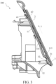
- FIG. 3 is a schematic diagram of a panel component during assembly.
- FIG. 4 is a schematic structural diagram of a body according to an embodiment of the utility model.
- FIG. 5 is a cross-sectional view of FIG. 4 along a direction B-B. A specific structure of the panel component is described below with reference to FIG. 1 to FIG. 5 .
- a panel component 100 includes a body 1 and a panel 2.
- the body 1 has a mounting surface 11.
- the panel 2 is connected to the mounting surface 11.
- the body 1 is provided with a cut-out 13 for forming a pull groove.
- the cut-out 13 includes a hidden portion located on the mounting surface 11, and at least part of the hidden portion is covered by the panel 2.
- the hidden portion of the cut-out 13 forming the pull groove is arranged on the mounting surface 11, and at least part of the hidden portion is covered by the panel 2, so as to reduce a possibility of exposure of a rear assembly structure arranged on the body 1 through the cut-out 13, thereby improving integrality of the panel component 100.
- the hidden portion is arranged on the mounting surface 11, so that the cut-out 13 may reuse space of the mounting surface 11, thereby reducing the space occupied by the cut-out 13 on the body 1, and realizing the reuse of the limited space of the panel component 100.
- the panel component 100 is easily designed to have a smaller space, to meet functional requirements of different types of household appliances, requirements for design space, and the like.
- a mounting direction y of the panel 2 is configured as a direction along a lower edge 112 of the mounting surface 11 to an upper edge 111 of the mounting surface 11.
- a cut-out direction of the hidden portion arranged on the mounting surface 11 is a direction along the lower edge 112 of the mounting surface 11 to the upper edge 111 of the mounting surface 11.
- the cut-out direction of the hidden portion is the same as the mounting direction y of the panel 2.
- the hidden portion of the cut-out 13 may be used as a part of a mounting space of the panel 2, to further increase a space utilization rate.
- the cut-out 13 is of an upward-oriented cut-out type, and can be reused as an ejection space of a mold, so that the mold for manufacturing the body 1 is machinable and realizable, and may further ensure that a thick space is provided that makes it possible for a steel material of the mold to have a corresponding strength.
- the body 1 further includes an arc-shaped transition surface 12.
- the arc-shaped transition surface 12 is connected to the mounting surface 11 and is located below the mounting surface 11.
- the arc-shaped transition surface 12 has a hollowed-out portion 14 in communication with the cut-out 13, and the hollowed-out portion 14 provides access to the pull groove.
- the arc-shaped transition surface 12 is a concave arc-shaped surface, that is, inclined and recessed along a direction of the panel 2 toward the body 1.
- the hollowed-out portion 14 may be provided below the panel 2.
- a back side 21 of the panel 2 is provided with a holding turnup 3.
- the holding turnup 3 is mated with the back side 21 of the panel 2 to form an accommodating groove 4.
- the accommodating groove 4 is open toward an upper edge 131 of the cut-out 13 and configured to accommodate the upper edge 131 of the cut-out 13, and the back side 21 of the panel 2 faces the mounting surface 11.
- the holding turnup 3 may provide the user with a holding region, which is convenient for the user to apply a force to pull out the panel component 100.
- a molded part or an entirety of a pull may be arranged on the panel 2, which not only may provide a pull-shaped human-computer interaction interface to facilitate operation by a user, but also may cause the upward-oriented cut-out 13 of the body 1 to be covered to a greater extent to ensure appearance integrality.
- the holding turnup 3 is arranged in a region of the panel 2 close to a lower edge thereof.
- a size of the holding turnup 3 is less than a size of the panel component 100.
- the mounting surface 11 has a bent portion 113 close to the lower edge 112 of the mounting surface 11.
- the bent portion 113 is bent in a direction close to the panel 2, and a part of the bent portion 113 is accommodated in the accommodating groove 4.
- the bent portion 113 may further enable a region where the body 1 contacts the holding turnup 3 to have better transition while ensuring that the upper edge 131 of the cut-out 13 is accommodated in the holding turnup 3, so that the user has a better holding feel thereby improving operating experience of the user.
- the holding turnup 3 does not exceed the back side 114 of the mounting surface 11.
- the back side 114 of the mounting surface 11 is away from the panel 2.
- a top portion 32 of the holding turnup 3 does not exceed an extension line of a region of the mounting surface 11 close to the bent portion 113. In this way, transition fluency of the region held by the user may be improved, to avoid a sudden change in the region where the holding turnup 3 contacts the body 1, thereby improving the operating experience of the user.
- a surface of the holding turnup 3 facing away from the panel 2 is an arc-shaped surface.
- the size of the holding turnup 3 is less than a size of the cut-out 13, to facilitate assembly of the panel component 100.
- FIG. 11 is a cross-sectional view of another panel according to an embodiment of the utility model.
- FIG. 12 is a schematic structural diagram of another panel component according to an embodiment of the utility model.
- a lower edge of the panel 2 is provided with a rib 7.
- the rib 7 extends in a direction of the body 1.
- the rib 7 and the panel 2 are connected (for example, integrally formed) and are L-shaped. At least part of the rib 7 extends into the cut-out 13 to occlude at least part of the hidden portion.
- FIG. 6 is a partial schematic structural diagram of FIG. 1 from a rear viewing angle.
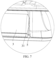
- FIG. 7 is a partial enlarged view of a part C in FIG. 6 .
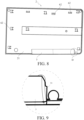
- FIG. 8 is a schematic structural diagram of a panel according to an embodiment of the utility model.
- FIG. 9 is a partial enlarged view of a part D in FIG. 8 .
- two ends of the holding turnup 3 are each provided with a reinforcing rib 31.
- Two ends of the reinforcing rib 31 are respectively connected to the holding turnup 3 and the back side 21 of the panel 2, so as to improve strength of the holding turnup 3 and prolong the service life of the holding turnup 3.
- the panel component 100 further includes a pair of side walls 5 connected to the body 1.
- the pair of side walls 5 are arranged along the length direction x of the body 1, and are respectively located at both ends of the holding turnup 3 as a sealing surface of the cut-out 13.
- the panel 2 illustrated in the foregoing accompanying drawings is a double-layer panel, including an inner layer 23 and an outer layer 22.
- the inner layer 23 and the outer layer 22 may be obtained by injection molding.
- the panel 2 may also be a single-layer panel, which is not limited in the utility model.
- the holding turnup 3 may be arranged on the inner layer 23, or may be arranged on both the inner layer 23 and the outer layer 22.
- the panel 2 and the body 1 may be connected in a snap-fitted manner.
- a snap 61 is arranged on the body 1, and a locking member 62 is arranged on the panel 2.
- the snap 61 may be a single-arm snap, or may be a double-arm snap.
- the double-arm snap may improve reliability of the connection between the panel 2 and the body 1. Arms of the double-arm snap may be configured as a straight line, or one arm may be configured as a straight line and the other arm may be configured as a curved line.
- the utility model further provides a household appliance, including any panel component described above.
- a household appliance including any panel component described above.
Landscapes
- Engineering & Computer Science (AREA)
- Textile Engineering (AREA)
- Detail Structures Of Washing Machines And Dryers (AREA)
- Casings For Electric Apparatus (AREA)
Abstract
Description
- Embodiments of the utility model relate to the technical field of household appliances, and in particular, to a panel component and a household appliance.
- Currently, some household appliances such as washing machines and clothes dryers are usually provided with panel components. For the panel component of a push-pull box body, aesthetics, mold realizability, design space, operating experience, and the like usually need to be considered, and pull grooves and panels need to be properly arranged.
- A technical problem resolved by the utility model is how to optimize arrangement of a panel component with a pull groove.
- To resolve the foregoing technical problem, embodiments of the utility model provide a panel component. The panel component is applied to the household appliance, and includes: a body, having a mounting surface; a panel, connected to the mounting surface. The body is provided with a cut-out for forming a pull groove, the cut-out includes a hidden portion located on the mounting surface, and at least part of the hidden portion is covered by the panel.
- Compared with the prior art, the technical solution in the embodiments of the utility model has the following beneficial effects.
- The hidden portion of the cut-out forming the pull groove is arranged on the mounting surface, and at least part of the hidden portion is covered by the panel, so as to reduce a possibility of exposure of a rear assembly structure arranged on the body through the cut-out, thereby improving integrality of the panel component.
- In addition, the hidden portion is arranged on the mounting surface, so that the cut-out may reuse space of the mounting surface, thereby reducing the space occupied by the cut-out on the body. Through reuse of a limited space of the panel component, the panel component is easily designed to have a smaller space, to meet functional requirements of different types of household appliances, requirements for design space, and the like.
- Optionally, a mounting direction of the panel is configured as a direction along a lower edge of the mounting surface to an upper edge of the mounting surface. In this way, a cut-out direction of the hidden portion is the same as the mounting direction of the panel. The hidden portion of the cut-out may be used as a part of a mounting space of the panel, to further increase a space utilization rate. In addition, the cut-out is of an upward-oriented cut-out type, and can be reused as an ejection space of a mold, so that the mold for manufacturing the body is machinable, and may ensure that a thick space is provided that makes it possible for a steel material of the mold to have a corresponding strength. Optionally, the body further includes an arc-shaped transition surface. The arc-shaped transition surface is connected to the mounting surface and is located below the mounting surface. The arc-shaped transition surface has a hollowed-out portion in communication with the cut-out, and the hollowed-out portion provides access to the pull groove.
- Optionally, a back side of the panel is provided with a holding turnup, the holding turnup is mated with the back side of the panel to form an accommodating groove, the accommodating groove is open toward an upper edge of the cut-out and configured to accommodate the upper edge of the cut-out, and the back side of the panel faces the mounting surface. When a user pushes or pulls the panel component, the holding turnup may provide the user with a holding region, which is convenient for the user to apply a force to pull out the panel component. In addition, a molded part or an entirety of a pull may be arranged on the panel, which not only may provide a pull-shaped human-computer interaction interface to facilitate operation by a user, but also may cause the upward-oriented cut-out of the body to be covered to a greater extent to ensure appearance integrality.
- Optionally, a lower edge of the panel is provided with a rib, and the rib extends in a direction of the body and at least partially extends into the cut-out to occlude at least part of the hidden portion, thereby hiding the cut-out from a front side of the panel component.
- Optionally, the mounting surface has a bent portion close to the lower edge of the mounting surface, the bent portion is bent in a direction close to the panel, and a part of the bent portion is accommodated in the accommodating groove. The bent portion may further enable a region where the body contacts the holding turnup to have better transition while ensuring that the upper edge of the cut-out is accommodated in the holding turnup, so that the user has a better holding feel thereby improving operating experience of the user.
- Optionally, along a direction perpendicular to the mounting surface, the holding turnup does not exceed the back side of the mounting surface, and the back side of the mounting surface is away from the panel. Transition fluency of the region held by the user may be improved, to avoid a sudden change in the region where the holding turnup contacts the body, thereby further improving the operating experience of the user.
- Optionally, a surface of the holding turnup facing away from the panel is an arc-shaped surface. In this way, a curvature of the holding turnup is consistent with a curvature of a flexed finger of the user, so that the finger of the user is more closely fitted to the holding turnup, thereby improving the operating experience of the user.
- Optionally, along a length direction of the body, a size of the holding turnup is less than a size of the cut-out, to facilitate assembly of the panel component.
- Optionally, the panel component further includes a pair of side walls connected to the body. The pair of side walls are arranged along the length direction of the body, and are respectively located at two ends of the holding turnup.
- The utility model further provides a household appliance, including any panel component described above.
-
FIG. 1 is a schematic structural diagram of a panel component according to an embodiment of the utility model. -
FIG. 2 is a cross-sectional view ofFIG. 1 along a direction A-A. -
FIG. 3 is a schematic diagram of a panel component during assembly. -
FIG. 4 is a schematic structural diagram of a body according to an embodiment of the utility model. -
FIG. 5 is a cross-sectional view ofFIG. 4 along a direction B-B. -
FIG. 6 is a partial schematic structural diagram ofFIG. 1 from a rear viewing angle. -
FIG. 7 is a partial enlarged view of a part C inFIG. 6 . -
FIG. 8 is a schematic structural diagram of a panel according to an embodiment of the utility model. -
FIG. 9 is a partial enlarged view of a part D inFIG. 8 . -
FIG. 10 is a cross-sectional view of a panel according to an embodiment of the utility model. -
FIG. 11 is a cross-sectional view of another panel according to an embodiment of the utility model. -
FIG. 12 is a schematic structural diagram of another panel component according to an embodiment of the utility model. - 100-Panel component; 1-Body; 11-Mounting surface; 111-Upper edge of the mounting surface; 112-Lower edge of the mounting surface; 113-Bent portion; 114-Back side of the mounting surface; 12-Arc-shaped transition surface; 13-Cut-out; 131-Upper edge of the cut-out; 14-Hollowed-out portion; 2-Panel; 21-Back side of the panel; 22-Outer layer; 23-Inner layer; 3-Holding turnup; 31-Reinforcing rib; 32-Top portion of the holding turnup; 4-Accommodating groove; 5-Side wall; 61-Snap; 62-Locking member; 7-Rib; x-Length direction x of the body; y-Assembly direction.
- To make the above objectives, features, and beneficial effects of the embodiments of the utility model more apparent and easier to understand, specific embodiments of the utility model are described in detail below with reference to accompanying drawings.
- The embodiments of the utility model provide a panel component. The panel component may be applied to a household appliance. The household appliance may be a washing machine, a clothes dryer, a washing and drying machine, or the like. The panel component may be applied to some push-pull box body components in the household appliance. The push-pull box body component may be a detergent feeding box component in the washing machine or the washing and drying machine, may be a condensate box component in the clothes dryer or the washing and drying machine, or the like. The panel component may also be used as a part of a control panel in the household appliance.
-
FIG. 1 is a schematic structural diagram of a panel component according to an embodiment of the utility model.FIG. 2 is a cross-sectional view ofFIG. 1 along a direction A-A.FIG. 3 is a schematic diagram of a panel component during assembly.FIG. 4 is a schematic structural diagram of a body according to an embodiment of the utility model.FIG. 5 is a cross-sectional view ofFIG. 4 along a direction B-B. A specific structure of the panel component is described below with reference toFIG. 1 to FIG. 5 . - In a specific implementation, a
panel component 100 includes abody 1 and apanel 2. Thebody 1 has amounting surface 11. Thepanel 2 is connected to themounting surface 11. Thebody 1 is provided with a cut-out 13 for forming a pull groove. The cut-out 13 includes a hidden portion located on themounting surface 11, and at least part of the hidden portion is covered by thepanel 2. - It may be learned from the above that the hidden portion of the cut-out 13 forming the pull groove is arranged on the
mounting surface 11, and at least part of the hidden portion is covered by thepanel 2, so as to reduce a possibility of exposure of a rear assembly structure arranged on thebody 1 through the cut-out 13, thereby improving integrality of thepanel component 100. - In addition, the hidden portion is arranged on the mounting
surface 11, so that the cut-out 13 may reuse space of the mountingsurface 11, thereby reducing the space occupied by the cut-out 13 on thebody 1, and realizing the reuse of the limited space of thepanel component 100. Through the reuse of the limited space of thepanel component 100, thepanel component 100 is easily designed to have a smaller space, to meet functional requirements of different types of household appliances, requirements for design space, and the like. - In a specific implementation, a mounting direction y of the
panel 2 is configured as a direction along alower edge 112 of the mountingsurface 11 to anupper edge 111 of the mountingsurface 11. A cut-out direction of the hidden portion arranged on the mountingsurface 11 is a direction along thelower edge 112 of the mountingsurface 11 to theupper edge 111 of the mountingsurface 11. In other words, the cut-out direction of the hidden portion is the same as the mounting direction y of thepanel 2. The hidden portion of the cut-out 13 may be used as a part of a mounting space of thepanel 2, to further increase a space utilization rate. In addition, the cut-out 13 is of an upward-oriented cut-out type, and can be reused as an ejection space of a mold, so that the mold for manufacturing thebody 1 is machinable and realizable, and may further ensure that a thick space is provided that makes it possible for a steel material of the mold to have a corresponding strength. - In a specific implementation, the
body 1 further includes an arc-shapedtransition surface 12. The arc-shapedtransition surface 12 is connected to the mountingsurface 11 and is located below the mountingsurface 11. The arc-shapedtransition surface 12 has a hollowed-out portion 14 in communication with the cut-out 13, and the hollowed-out portion 14 provides access to the pull groove. - In some embodiments, the arc-shaped
transition surface 12 is a concave arc-shaped surface, that is, inclined and recessed along a direction of thepanel 2 toward thebody 1. In this way, the hollowed-out portion 14 may be provided below thepanel 2. When a user looks at thepanel component 100 from a front side, the hollowed-out portion 14 is not easily noticed, thereby hiding the hollowed-out portion 14 as much as possible. - In some embodiments, a
back side 21 of thepanel 2 is provided with a holdingturnup 3. The holdingturnup 3 is mated with theback side 21 of thepanel 2 to form anaccommodating groove 4. Theaccommodating groove 4 is open toward anupper edge 131 of the cut-out 13 and configured to accommodate theupper edge 131 of the cut-out 13, and theback side 21 of thepanel 2 faces the mountingsurface 11. When a user pushes or pulls thepanel component 100, the holdingturnup 3 may provide the user with a holding region, which is convenient for the user to apply a force to pull out thepanel component 100. In addition, a molded part or an entirety of a pull may be arranged on thepanel 2, which not only may provide a pull-shaped human-computer interaction interface to facilitate operation by a user, but also may cause the upward-oriented cut-out 13 of thebody 1 to be covered to a greater extent to ensure appearance integrality. - Further, the holding
turnup 3 is arranged in a region of thepanel 2 close to a lower edge thereof. - In some embodiments, along a length direction x of the
body 1, a size of the holdingturnup 3 is less than a size of thepanel component 100. - The mounting
surface 11 has abent portion 113 close to thelower edge 112 of the mountingsurface 11. Thebent portion 113 is bent in a direction close to thepanel 2, and a part of thebent portion 113 is accommodated in theaccommodating groove 4. Thebent portion 113 may further enable a region where thebody 1 contacts the holdingturnup 3 to have better transition while ensuring that theupper edge 131 of the cut-out 13 is accommodated in the holdingturnup 3, so that the user has a better holding feel thereby improving operating experience of the user. - Further, along a direction perpendicular to the mounting
surface 11, the holdingturnup 3 does not exceed theback side 114 of the mountingsurface 11. Theback side 114 of the mountingsurface 11 is away from thepanel 2. In other words, atop portion 32 of the holdingturnup 3 does not exceed an extension line of a region of the mountingsurface 11 close to thebent portion 113. In this way, transition fluency of the region held by the user may be improved, to avoid a sudden change in the region where the holdingturnup 3 contacts thebody 1, thereby improving the operating experience of the user. - Further, a surface of the holding
turnup 3 facing away from thepanel 2 is an arc-shaped surface. In this way, a curvature of the holdingturnup 3 is consistent with a curvature of a flexed finger of the user, so that the finger of the user is more closely fitted to the holdingturnup 3, thereby improving the operating experience of the user. - Along the length direction x of the
body 1, the size of the holdingturnup 3 is less than a size of the cut-out 13, to facilitate assembly of thepanel component 100. -
FIG. 11 is a cross-sectional view of another panel according to an embodiment of the utility model.FIG. 12 is a schematic structural diagram of another panel component according to an embodiment of the utility model. In some other embodiments, a lower edge of thepanel 2 is provided with arib 7. Therib 7 extends in a direction of thebody 1. In other words, therib 7 and thepanel 2 are connected (for example, integrally formed) and are L-shaped. At least part of therib 7 extends into the cut-out 13 to occlude at least part of the hidden portion. -
FIG. 6 is a partial schematic structural diagram ofFIG. 1 from a rear viewing angle.FIG. 7 is a partial enlarged view of a part C inFIG. 6 .FIG. 8 is a schematic structural diagram of a panel according to an embodiment of the utility model.FIG. 9 is a partial enlarged view of a part D inFIG. 8 . - In some non-limiting embodiments, with reference to
FIG. 1 to FIG. 9 , two ends of the holdingturnup 3 are each provided with a reinforcingrib 31. Two ends of the reinforcingrib 31 are respectively connected to the holdingturnup 3 and theback side 21 of thepanel 2, so as to improve strength of the holdingturnup 3 and prolong the service life of the holdingturnup 3. - With reference to
FIG. 6 andFIG. 7 , thepanel component 100 further includes a pair ofside walls 5 connected to thebody 1. The pair ofside walls 5 are arranged along the length direction x of thebody 1, and are respectively located at both ends of the holdingturnup 3 as a sealing surface of the cut-out 13. - It is to be noted that with reference to
FIG. 10 , a cross-sectional view of a panel according to an embodiment of the utility model is provided. Thepanel 2 illustrated in the foregoing accompanying drawings is a double-layer panel, including aninner layer 23 and anouter layer 22. Theinner layer 23 and theouter layer 22 may be obtained by injection molding. In practice, thepanel 2 may also be a single-layer panel, which is not limited in the utility model. - When the
panel 2 is the double-layer panel, the holdingturnup 3 may be arranged on theinner layer 23, or may be arranged on both theinner layer 23 and theouter layer 22. - The
panel 2 and thebody 1 may be connected in a snap-fitted manner. Asnap 61 is arranged on thebody 1, and a lockingmember 62 is arranged on thepanel 2. Thesnap 61 may be a single-arm snap, or may be a double-arm snap. The double-arm snap may improve reliability of the connection between thepanel 2 and thebody 1. Arms of the double-arm snap may be configured as a straight line, or one arm may be configured as a straight line and the other arm may be configured as a curved line. - The utility model further provides a household appliance, including any panel component described above. For a specific structure of the panel component, reference may be made to the description in the foregoing embodiments, and details are not described herein again.
- Although the specific implementations have been described above, these implementations are not intended to limit the scope disclosed in the utility model, even if the same is true for a case that a single implementation is described only with respect to specific features. The feature examples provided in the utility model are intended for illustration but not limitation, unless otherwise stated. In a specific implementation, the technical features of one or more dependent claims may be combined with the technical features of the independent claims based on actual requirements when technically feasible, and the technical features from the corresponding independent claims may be combined in any appropriate manner, not only through the specific combination listed in the claims.
- Although the utility model is disclosed above, the utility model is not limited thereto. Various alterations and modifications may be made by a person skilled in the art without departing from the spirit and scope of the utility model, and therefore the protection scope of the utility model should be subject to the scope defined by the claims.
Claims (10)
- A panel component, applied to a household appliance, characterized by comprising:a body (1), having a mounting surface (11);a panel (2), connected to the mounting surface (11),whereinthe body (1) is provided with a cut-out (13) for forming a pull groove, the cut-out (13) comprises a hidden portion located on the mounting surface (11), and at least part of the hidden portion is covered by the panel (2).
- The panel component according to claim 1, characterized in that a mounting direction of the panel (2) is configured as a direction along a lower edge (112) of the mounting surface (11) to an upper edge (111) of the mounting surface (11).
- The panel component according to claim 1, characterized in that the body (1) further comprises an arc-shaped transition surface (12), the arc-shaped transition surface (12) is connected to the mounting surface (11) and is located below the mounting surface (11), the arc-shaped transition surface (12) has a hollowed-out portion (14) in communication with the cut-out (13), and the hollowed-out portion (14) provides access to the pull groove.
- The panel component according to any of claims 1 to 3, characterized in that a back side (21) of the panel (2) is provided with a holding turnup (3), the holding turnup (3) is mated with the back side (21) of the panel (2) to form an accommodating groove (4), the accommodating groove (4) is open toward an upper edge (131) of the cut-out (13) and configured to accommodate the upper edge (131) of the cut-out (13), and the back side (21) of the panel (2) faces the mounting surface (11); or
a lower edge of the panel (2) is provided with a rib (7), and the rib (7) extends in a direction of the body (1) and at least partially extends into the cut-out (13) to occlude at least part of the hidden portion. - The panel component according to claim 4, characterized in that the mounting surface (11) has a bent portion (113) close to the lower edge (112) of the mounting surface (11), the bent portion (113) is bent in a direction close to the panel (2), and a part of the bent portion (113) is accommodated in the accommodating groove (4).
- The panel component according to claim 5, characterized in that along a direction perpendicular to the mounting surface (11), the holding turnup (3) does not exceed the back side (114) of the mounting surface (11), and the back side (114) of the mounting surface (11) is away from the panel (2).
- The panel component according to claim 4, characterized in that a surface of the holding turnup (3) facing away from the panel (2) is an arc-shaped surface.
- The panel component according to claim 4, characterized in that along a length direction (x) of the body (1), a size of the holding turnup (3) is less than a size of the cut-out (13).
- The panel component according to claim 4, characterized by further comprising a pair of side walls (5) connected to the body (1), wherein the pair of side walls (5) are arranged along a length direction (x) of the body (1), and are respectively located at two ends of the holding turnup (3).
- A household appliance, characterized by comprising the panel component (100) according to any of claims 1 to 9.
Applications Claiming Priority (1)
| Application Number | Priority Date | Filing Date | Title |
|---|---|---|---|
| CN202322058078.6U CN221052196U (en) | 2023-08-01 | 2023-08-01 | Panel components and household appliances |
Publications (2)
| Publication Number | Publication Date |
|---|---|
| EP4502265A1 true EP4502265A1 (en) | 2025-02-05 |
| EP4502265B1 EP4502265B1 (en) | 2026-05-20 |
Family
ID=91203237
Family Applications (1)
| Application Number | Title | Priority Date | Filing Date |
|---|---|---|---|
| EP24192063.6A Active EP4502265B1 (en) | 2023-08-01 | 2024-07-31 | Panel component and household appliance |
Country Status (2)
| Country | Link |
|---|---|
| EP (1) | EP4502265B1 (en) |
| CN (1) | CN221052196U (en) |
Citations (4)
| Publication number | Priority date | Publication date | Assignee | Title |
|---|---|---|---|---|
| US20150003027A1 (en) * | 2013-06-04 | 2015-01-01 | Lg Electronics Inc. | Laundry treating apparatus |
| WO2017059907A1 (en) * | 2015-10-08 | 2017-04-13 | Arcelik Anonim Sirketi | Drawer assembly for a laundry machine |
| CN106884282A (en) * | 2015-12-16 | 2017-06-23 | 青岛海尔滚筒洗衣机有限公司 | A kind of detergent box and roller washing machine |
| US20210172108A1 (en) * | 2019-12-06 | 2021-06-10 | Samsung Electronics Co., Ltd. | Detergent supply device and washing machine including the same |
-
2023
- 2023-08-01 CN CN202322058078.6U patent/CN221052196U/en active Active
-
2024
- 2024-07-31 EP EP24192063.6A patent/EP4502265B1/en active Active
Patent Citations (4)
| Publication number | Priority date | Publication date | Assignee | Title |
|---|---|---|---|---|
| US20150003027A1 (en) * | 2013-06-04 | 2015-01-01 | Lg Electronics Inc. | Laundry treating apparatus |
| WO2017059907A1 (en) * | 2015-10-08 | 2017-04-13 | Arcelik Anonim Sirketi | Drawer assembly for a laundry machine |
| CN106884282A (en) * | 2015-12-16 | 2017-06-23 | 青岛海尔滚筒洗衣机有限公司 | A kind of detergent box and roller washing machine |
| US20210172108A1 (en) * | 2019-12-06 | 2021-06-10 | Samsung Electronics Co., Ltd. | Detergent supply device and washing machine including the same |
Also Published As
| Publication number | Publication date |
|---|---|
| EP4502265B1 (en) | 2026-05-20 |
| CN221052196U (en) | 2024-05-31 |
Similar Documents
| Publication | Publication Date | Title |
|---|---|---|
| JP5370230B2 (en) | Washing machine lid device and washing machine equipped with the same | |
| US12102280B2 (en) | Dishwasher | |
| EP2594184A1 (en) | Dishwasher | |
| CN101962902B (en) | Drum type washing machine | |
| EP3345527B1 (en) | Front panel for a door for a household appliance | |
| CN104337487B (en) | Door lock and the dish-washing machine for being equipped with door lock | |
| CN210002115U (en) | kinds of detergents put in device and washing machine | |
| CN221052196U (en) | Panel components and household appliances | |
| CN109338676A (en) | A washing machine water box and washing machine | |
| CN107916544A (en) | Tumbling-box washing machine | |
| CN210420595U (en) | Washing liquid box subassembly and washing machine | |
| CN112709492B (en) | Door latch for electrical household appliances and method of installing such a door latch | |
| CN217869585U (en) | Wall-hanging clothing treatment facility and preceding door assembly that seals thereof | |
| AU2020225795A1 (en) | Dishwasher | |
| CN212307768U (en) | Dish washing machine | |
| CN215906431U (en) | Front sealing door of clothes treatment device and clothes treatment device | |
| CN205874758U (en) | Button assembly and washing machine | |
| US20130175149A1 (en) | Button spring | |
| CN218523823U (en) | Household appliance and front cover of box body thereof | |
| CN217471903U (en) | Spraying arm for dish washing machine and dish washing machine with spraying arm | |
| CN216124082U (en) | Goods selling storage box | |
| CN216745130U (en) | Door shell for refrigerator, door body for refrigerator and refrigerator | |
| KR20120008685A (en) | Door for washing machine | |
| CN220099450U (en) | Board and clothing processing device | |
| CN214505331U (en) | Key assembly and electrical equipment |
Legal Events
| Date | Code | Title | Description |
|---|---|---|---|
| PUAI | Public reference made under article 153(3) epc to a published international application that has entered the european phase |
Free format text: ORIGINAL CODE: 0009012 |
|
| STAA | Information on the status of an ep patent application or granted ep patent |
Free format text: STATUS: THE APPLICATION HAS BEEN PUBLISHED |
|
| AK | Designated contracting states |
Kind code of ref document: A1 Designated state(s): AL AT BE BG CH CY CZ DE DK EE ES FI FR GB GR HR HU IE IS IT LI LT LU LV MC ME MK MT NL NO PL PT RO RS SE SI SK SM TR |
|
| STAA | Information on the status of an ep patent application or granted ep patent |
Free format text: STATUS: REQUEST FOR EXAMINATION WAS MADE |
|
| 17P | Request for examination filed |
Effective date: 20250805 |
|
| GRAP | Despatch of communication of intention to grant a patent |
Free format text: ORIGINAL CODE: EPIDOSNIGR1 |
|
| STAA | Information on the status of an ep patent application or granted ep patent |
Free format text: STATUS: GRANT OF PATENT IS INTENDED |
|
| RIC1 | Information provided on ipc code assigned before grant |
Ipc: D06F 39/12 20060101AFI20251219BHEP Ipc: D06F 39/02 20060101ALN20251219BHEP Ipc: D06F 58/24 20060101ALN20251219BHEP Ipc: D06F 34/34 20200101ALN20251219BHEP Ipc: A47L 15/42 20060101ALN20251219BHEP |
|
| RIC1 | Information provided on ipc code assigned before grant |
Ipc: D06F 39/12 20060101AFI20260113BHEP Ipc: D06F 39/02 20060101ALN20260113BHEP Ipc: D06F 58/24 20060101ALN20260113BHEP Ipc: D06F 34/34 20200101ALN20260113BHEP Ipc: A47L 15/42 20060101ALN20260113BHEP |
|
| INTG | Intention to grant announced |
Effective date: 20260127 |
|
| GRAS | Grant fee paid |
Free format text: ORIGINAL CODE: EPIDOSNIGR3 |
|
| GRAA | (expected) grant |
Free format text: ORIGINAL CODE: 0009210 |
|
| STAA | Information on the status of an ep patent application or granted ep patent |
Free format text: STATUS: THE PATENT HAS BEEN GRANTED |