EP4502259A1 - Garment - Google Patents
Garment Download PDFInfo
- Publication number
- EP4502259A1 EP4502259A1 EP23780032.1A EP23780032A EP4502259A1 EP 4502259 A1 EP4502259 A1 EP 4502259A1 EP 23780032 A EP23780032 A EP 23780032A EP 4502259 A1 EP4502259 A1 EP 4502259A1
- Authority
- EP
- European Patent Office
- Prior art keywords
- nonwoven fabric
- cloth
- layered
- tape member
- region
- Prior art date
- Legal status (The legal status is an assumption and is not a legal conclusion. Google has not performed a legal analysis and makes no representation as to the accuracy of the status listed.)
- Pending
Links
Images


Classifications
-
- A—HUMAN NECESSITIES
- A41—WEARING APPAREL
- A41D—OUTERWEAR; PROTECTIVE GARMENTS; ACCESSORIES
- A41D31/00—Materials specially adapted for outerwear
- A41D31/02—Layered materials
-
- A—HUMAN NECESSITIES
- A41—WEARING APPAREL
- A41D—OUTERWEAR; PROTECTIVE GARMENTS; ACCESSORIES
- A41D27/00—Details of garments or of their making
- A41D27/24—Hems; Seams
- A41D27/245—Hems; Seams made by welding or gluing
-
- A—HUMAN NECESSITIES
- A41—WEARING APPAREL
- A41D—OUTERWEAR; PROTECTIVE GARMENTS; ACCESSORIES
- A41D31/00—Materials specially adapted for outerwear
- A41D31/04—Materials specially adapted for outerwear characterised by special function or use
- A41D31/10—Impermeable to liquids, e.g. waterproof; Liquid-repellent
-
- A—HUMAN NECESSITIES
- A41—WEARING APPAREL
- A41D—OUTERWEAR; PROTECTIVE GARMENTS; ACCESSORIES
- A41D31/00—Materials specially adapted for outerwear
- A41D31/04—Materials specially adapted for outerwear characterised by special function or use
- A41D31/26—Electrically protective, e.g. preventing static electricity or electric shock
- A41D31/265—Electrically protective, e.g. preventing static electricity or electric shock using layered materials
-
- B—PERFORMING OPERATIONS; TRANSPORTING
- B32—LAYERED PRODUCTS
- B32B—LAYERED PRODUCTS, i.e. PRODUCTS BUILT-UP OF STRATA OF FLAT OR NON-FLAT, e.g. CELLULAR OR HONEYCOMB, FORM
- B32B27/00—Layered products comprising a layer of synthetic resin
- B32B27/12—Layered products comprising a layer of synthetic resin next to a fibrous or filamentary layer
-
- B—PERFORMING OPERATIONS; TRANSPORTING
- B32—LAYERED PRODUCTS
- B32B—LAYERED PRODUCTS, i.e. PRODUCTS BUILT-UP OF STRATA OF FLAT OR NON-FLAT, e.g. CELLULAR OR HONEYCOMB, FORM
- B32B27/00—Layered products comprising a layer of synthetic resin
- B32B27/32—Layered products comprising a layer of synthetic resin comprising polyolefins
-
- B—PERFORMING OPERATIONS; TRANSPORTING
- B32—LAYERED PRODUCTS
- B32B—LAYERED PRODUCTS, i.e. PRODUCTS BUILT-UP OF STRATA OF FLAT OR NON-FLAT, e.g. CELLULAR OR HONEYCOMB, FORM
- B32B3/00—Layered products comprising a layer with external or internal discontinuities or unevennesses, or a layer of non-planar shape; Layered products comprising a layer having particular features of form
- B32B3/02—Layered products comprising a layer with external or internal discontinuities or unevennesses, or a layer of non-planar shape; Layered products comprising a layer having particular features of form characterised by features of form at particular places, e.g. in edge regions
- B32B3/06—Layered products comprising a layer with external or internal discontinuities or unevennesses, or a layer of non-planar shape; Layered products comprising a layer having particular features of form characterised by features of form at particular places, e.g. in edge regions for securing layers together; for attaching the product to another member, e.g. to a support, or to another product, e.g. groove/tongue, interlocking
-
- B—PERFORMING OPERATIONS; TRANSPORTING
- B32—LAYERED PRODUCTS
- B32B—LAYERED PRODUCTS, i.e. PRODUCTS BUILT-UP OF STRATA OF FLAT OR NON-FLAT, e.g. CELLULAR OR HONEYCOMB, FORM
- B32B3/00—Layered products comprising a layer with external or internal discontinuities or unevennesses, or a layer of non-planar shape; Layered products comprising a layer having particular features of form
- B32B3/02—Layered products comprising a layer with external or internal discontinuities or unevennesses, or a layer of non-planar shape; Layered products comprising a layer having particular features of form characterised by features of form at particular places, e.g. in edge regions
- B32B3/08—Layered products comprising a layer with external or internal discontinuities or unevennesses, or a layer of non-planar shape; Layered products comprising a layer having particular features of form characterised by features of form at particular places, e.g. in edge regions characterised by added members at particular parts
-
- B—PERFORMING OPERATIONS; TRANSPORTING
- B32—LAYERED PRODUCTS
- B32B—LAYERED PRODUCTS, i.e. PRODUCTS BUILT-UP OF STRATA OF FLAT OR NON-FLAT, e.g. CELLULAR OR HONEYCOMB, FORM
- B32B5/00—Layered products characterised by the non- homogeneity or physical structure, i.e. comprising a fibrous, filamentary, particulate or foam layer; Layered products characterised by having a layer differing constitutionally or physically in different parts
- B32B5/02—Layered products characterised by the non- homogeneity or physical structure, i.e. comprising a fibrous, filamentary, particulate or foam layer; Layered products characterised by having a layer differing constitutionally or physically in different parts characterised by structural features of a fibrous or filamentary layer
- B32B5/022—Non-woven fabric
-
- B—PERFORMING OPERATIONS; TRANSPORTING
- B32—LAYERED PRODUCTS
- B32B—LAYERED PRODUCTS, i.e. PRODUCTS BUILT-UP OF STRATA OF FLAT OR NON-FLAT, e.g. CELLULAR OR HONEYCOMB, FORM
- B32B5/00—Layered products characterised by the non- homogeneity or physical structure, i.e. comprising a fibrous, filamentary, particulate or foam layer; Layered products characterised by having a layer differing constitutionally or physically in different parts
- B32B5/02—Layered products characterised by the non- homogeneity or physical structure, i.e. comprising a fibrous, filamentary, particulate or foam layer; Layered products characterised by having a layer differing constitutionally or physically in different parts characterised by structural features of a fibrous or filamentary layer
- B32B5/06—Layered products characterised by the non- homogeneity or physical structure, i.e. comprising a fibrous, filamentary, particulate or foam layer; Layered products characterised by having a layer differing constitutionally or physically in different parts characterised by structural features of a fibrous or filamentary layer characterised by a fibrous or filamentary layer mechanically connected, e.g. by needling to another layer, e.g. of fibres, of paper
-
- B—PERFORMING OPERATIONS; TRANSPORTING
- B32—LAYERED PRODUCTS
- B32B—LAYERED PRODUCTS, i.e. PRODUCTS BUILT-UP OF STRATA OF FLAT OR NON-FLAT, e.g. CELLULAR OR HONEYCOMB, FORM
- B32B5/00—Layered products characterised by the non- homogeneity or physical structure, i.e. comprising a fibrous, filamentary, particulate or foam layer; Layered products characterised by having a layer differing constitutionally or physically in different parts
- B32B5/22—Layered products characterised by the non- homogeneity or physical structure, i.e. comprising a fibrous, filamentary, particulate or foam layer; Layered products characterised by having a layer differing constitutionally or physically in different parts characterised by the presence of two or more layers which are next to each other and are fibrous, filamentary, formed of particles or foamed
- B32B5/24—Layered products characterised by the non- homogeneity or physical structure, i.e. comprising a fibrous, filamentary, particulate or foam layer; Layered products characterised by having a layer differing constitutionally or physically in different parts characterised by the presence of two or more layers which are next to each other and are fibrous, filamentary, formed of particles or foamed one layer being a fibrous or filamentary layer
- B32B5/26—Layered products characterised by the non- homogeneity or physical structure, i.e. comprising a fibrous, filamentary, particulate or foam layer; Layered products characterised by having a layer differing constitutionally or physically in different parts characterised by the presence of two or more layers which are next to each other and are fibrous, filamentary, formed of particles or foamed one layer being a fibrous or filamentary layer another layer next to it also being fibrous or filamentary
- B32B5/265—Layered products characterised by the non- homogeneity or physical structure, i.e. comprising a fibrous, filamentary, particulate or foam layer; Layered products characterised by having a layer differing constitutionally or physically in different parts characterised by the presence of two or more layers which are next to each other and are fibrous, filamentary, formed of particles or foamed one layer being a fibrous or filamentary layer another layer next to it also being fibrous or filamentary characterised by one fibrous or filamentary layer being a non-woven fabric layer
- B32B5/266—Layered products characterised by the non- homogeneity or physical structure, i.e. comprising a fibrous, filamentary, particulate or foam layer; Layered products characterised by having a layer differing constitutionally or physically in different parts characterised by the presence of two or more layers which are next to each other and are fibrous, filamentary, formed of particles or foamed one layer being a fibrous or filamentary layer another layer next to it also being fibrous or filamentary characterised by one fibrous or filamentary layer being a non-woven fabric layer next to one or more non-woven fabric layers
-
- B—PERFORMING OPERATIONS; TRANSPORTING
- B32—LAYERED PRODUCTS
- B32B—LAYERED PRODUCTS, i.e. PRODUCTS BUILT-UP OF STRATA OF FLAT OR NON-FLAT, e.g. CELLULAR OR HONEYCOMB, FORM
- B32B5/00—Layered products characterised by the non- homogeneity or physical structure, i.e. comprising a fibrous, filamentary, particulate or foam layer; Layered products characterised by having a layer differing constitutionally or physically in different parts
- B32B5/22—Layered products characterised by the non- homogeneity or physical structure, i.e. comprising a fibrous, filamentary, particulate or foam layer; Layered products characterised by having a layer differing constitutionally or physically in different parts characterised by the presence of two or more layers which are next to each other and are fibrous, filamentary, formed of particles or foamed
- B32B5/24—Layered products characterised by the non- homogeneity or physical structure, i.e. comprising a fibrous, filamentary, particulate or foam layer; Layered products characterised by having a layer differing constitutionally or physically in different parts characterised by the presence of two or more layers which are next to each other and are fibrous, filamentary, formed of particles or foamed one layer being a fibrous or filamentary layer
- B32B5/26—Layered products characterised by the non- homogeneity or physical structure, i.e. comprising a fibrous, filamentary, particulate or foam layer; Layered products characterised by having a layer differing constitutionally or physically in different parts characterised by the presence of two or more layers which are next to each other and are fibrous, filamentary, formed of particles or foamed one layer being a fibrous or filamentary layer another layer next to it also being fibrous or filamentary
- B32B5/265—Layered products characterised by the non- homogeneity or physical structure, i.e. comprising a fibrous, filamentary, particulate or foam layer; Layered products characterised by having a layer differing constitutionally or physically in different parts characterised by the presence of two or more layers which are next to each other and are fibrous, filamentary, formed of particles or foamed one layer being a fibrous or filamentary layer another layer next to it also being fibrous or filamentary characterised by one fibrous or filamentary layer being a non-woven fabric layer
- B32B5/266—Layered products characterised by the non- homogeneity or physical structure, i.e. comprising a fibrous, filamentary, particulate or foam layer; Layered products characterised by having a layer differing constitutionally or physically in different parts characterised by the presence of two or more layers which are next to each other and are fibrous, filamentary, formed of particles or foamed one layer being a fibrous or filamentary layer another layer next to it also being fibrous or filamentary characterised by one fibrous or filamentary layer being a non-woven fabric layer next to one or more non-woven fabric layers
- B32B5/268—Layered products characterised by the non- homogeneity or physical structure, i.e. comprising a fibrous, filamentary, particulate or foam layer; Layered products characterised by having a layer differing constitutionally or physically in different parts characterised by the presence of two or more layers which are next to each other and are fibrous, filamentary, formed of particles or foamed one layer being a fibrous or filamentary layer another layer next to it also being fibrous or filamentary characterised by one fibrous or filamentary layer being a non-woven fabric layer next to one or more non-woven fabric layers characterised by at least one non-woven fabric layer that is a melt-blown fabric
- B32B5/269—Layered products characterised by the non- homogeneity or physical structure, i.e. comprising a fibrous, filamentary, particulate or foam layer; Layered products characterised by having a layer differing constitutionally or physically in different parts characterised by the presence of two or more layers which are next to each other and are fibrous, filamentary, formed of particles or foamed one layer being a fibrous or filamentary layer another layer next to it also being fibrous or filamentary characterised by one fibrous or filamentary layer being a non-woven fabric layer next to one or more non-woven fabric layers characterised by at least one non-woven fabric layer that is a melt-blown fabric characterised by at least one non-woven fabric layer that is a melt-blown fabric next to a non-woven fabric layer that is a spunbonded fabric
-
- B—PERFORMING OPERATIONS; TRANSPORTING
- B32—LAYERED PRODUCTS
- B32B—LAYERED PRODUCTS, i.e. PRODUCTS BUILT-UP OF STRATA OF FLAT OR NON-FLAT, e.g. CELLULAR OR HONEYCOMB, FORM
- B32B7/00—Layered products characterised by the relation between layers; Layered products characterised by the relative orientation of features between layers, or by the relative values of a measurable parameter between layers, i.e. products comprising layers having different physical, chemical or physicochemical properties; Layered products characterised by the interconnection of layers
- B32B7/04—Interconnection of layers
- B32B7/05—Interconnection of layers the layers not being connected over the whole surface, e.g. discontinuous connection or patterned connection
-
- B—PERFORMING OPERATIONS; TRANSPORTING
- B32—LAYERED PRODUCTS
- B32B—LAYERED PRODUCTS, i.e. PRODUCTS BUILT-UP OF STRATA OF FLAT OR NON-FLAT, e.g. CELLULAR OR HONEYCOMB, FORM
- B32B7/00—Layered products characterised by the relation between layers; Layered products characterised by the relative orientation of features between layers, or by the relative values of a measurable parameter between layers, i.e. products comprising layers having different physical, chemical or physicochemical properties; Layered products characterised by the interconnection of layers
- B32B7/04—Interconnection of layers
- B32B7/08—Interconnection of layers by mechanical means
-
- B—PERFORMING OPERATIONS; TRANSPORTING
- B32—LAYERED PRODUCTS
- B32B—LAYERED PRODUCTS, i.e. PRODUCTS BUILT-UP OF STRATA OF FLAT OR NON-FLAT, e.g. CELLULAR OR HONEYCOMB, FORM
- B32B7/00—Layered products characterised by the relation between layers; Layered products characterised by the relative orientation of features between layers, or by the relative values of a measurable parameter between layers, i.e. products comprising layers having different physical, chemical or physicochemical properties; Layered products characterised by the interconnection of layers
- B32B7/04—Interconnection of layers
- B32B7/12—Interconnection of layers using interposed adhesives or interposed materials with bonding properties
-
- D—TEXTILES; PAPER
- D04—BRAIDING; LACE-MAKING; KNITTING; TRIMMINGS; NON-WOVEN FABRICS
- D04H—MAKING TEXTILE FABRICS, e.g. FROM FIBRES OR FILAMENTARY MATERIAL; FABRICS MADE BY SUCH PROCESSES OR APPARATUS, e.g. FELTS, NON-WOVEN FABRICS; COTTON-WOOL; WADDING ; NON-WOVEN FABRICS FROM STAPLE FIBRES, FILAMENTS OR YARNS, BONDED WITH AT LEAST ONE WEB-LIKE MATERIAL DURING THEIR CONSOLIDATION
- D04H1/00—Non-woven fabrics formed wholly or mainly of staple fibres or like relatively short fibres
- D04H1/40—Non-woven fabrics formed wholly or mainly of staple fibres or like relatively short fibres from fleeces or layers composed of fibres without existing or potential cohesive properties
- D04H1/42—Non-woven fabrics formed wholly or mainly of staple fibres or like relatively short fibres from fleeces or layers composed of fibres without existing or potential cohesive properties characterised by the use of certain kinds of fibres insofar as this use has no preponderant influence on the consolidation of the fleece
- D04H1/4282—Addition polymers
- D04H1/4291—Olefin series
-
- D—TEXTILES; PAPER
- D04—BRAIDING; LACE-MAKING; KNITTING; TRIMMINGS; NON-WOVEN FABRICS
- D04H—MAKING TEXTILE FABRICS, e.g. FROM FIBRES OR FILAMENTARY MATERIAL; FABRICS MADE BY SUCH PROCESSES OR APPARATUS, e.g. FELTS, NON-WOVEN FABRICS; COTTON-WOOL; WADDING ; NON-WOVEN FABRICS FROM STAPLE FIBRES, FILAMENTS OR YARNS, BONDED WITH AT LEAST ONE WEB-LIKE MATERIAL DURING THEIR CONSOLIDATION
- D04H1/00—Non-woven fabrics formed wholly or mainly of staple fibres or like relatively short fibres
- D04H1/40—Non-woven fabrics formed wholly or mainly of staple fibres or like relatively short fibres from fleeces or layers composed of fibres without existing or potential cohesive properties
- D04H1/42—Non-woven fabrics formed wholly or mainly of staple fibres or like relatively short fibres from fleeces or layers composed of fibres without existing or potential cohesive properties characterised by the use of certain kinds of fibres insofar as this use has no preponderant influence on the consolidation of the fleece
- D04H1/4382—Stretched reticular film fibres; Composite fibres; Mixed fibres; Ultrafine fibres; Fibres for artificial leather
- D04H1/43838—Ultrafine fibres, e.g. microfibres
-
- D—TEXTILES; PAPER
- D04—BRAIDING; LACE-MAKING; KNITTING; TRIMMINGS; NON-WOVEN FABRICS
- D04H—MAKING TEXTILE FABRICS, e.g. FROM FIBRES OR FILAMENTARY MATERIAL; FABRICS MADE BY SUCH PROCESSES OR APPARATUS, e.g. FELTS, NON-WOVEN FABRICS; COTTON-WOOL; WADDING ; NON-WOVEN FABRICS FROM STAPLE FIBRES, FILAMENTS OR YARNS, BONDED WITH AT LEAST ONE WEB-LIKE MATERIAL DURING THEIR CONSOLIDATION
- D04H1/00—Non-woven fabrics formed wholly or mainly of staple fibres or like relatively short fibres
- D04H1/40—Non-woven fabrics formed wholly or mainly of staple fibres or like relatively short fibres from fleeces or layers composed of fibres without existing or potential cohesive properties
- D04H1/54—Non-woven fabrics formed wholly or mainly of staple fibres or like relatively short fibres from fleeces or layers composed of fibres without existing or potential cohesive properties by welding together the fibres, e.g. by partially melting or dissolving
- D04H1/555—Non-woven fabrics formed wholly or mainly of staple fibres or like relatively short fibres from fleeces or layers composed of fibres without existing or potential cohesive properties by welding together the fibres, e.g. by partially melting or dissolving by ultrasonic heating
-
- D—TEXTILES; PAPER
- D04—BRAIDING; LACE-MAKING; KNITTING; TRIMMINGS; NON-WOVEN FABRICS
- D04H—MAKING TEXTILE FABRICS, e.g. FROM FIBRES OR FILAMENTARY MATERIAL; FABRICS MADE BY SUCH PROCESSES OR APPARATUS, e.g. FELTS, NON-WOVEN FABRICS; COTTON-WOOL; WADDING ; NON-WOVEN FABRICS FROM STAPLE FIBRES, FILAMENTS OR YARNS, BONDED WITH AT LEAST ONE WEB-LIKE MATERIAL DURING THEIR CONSOLIDATION
- D04H1/00—Non-woven fabrics formed wholly or mainly of staple fibres or like relatively short fibres
- D04H1/40—Non-woven fabrics formed wholly or mainly of staple fibres or like relatively short fibres from fleeces or layers composed of fibres without existing or potential cohesive properties
- D04H1/54—Non-woven fabrics formed wholly or mainly of staple fibres or like relatively short fibres from fleeces or layers composed of fibres without existing or potential cohesive properties by welding together the fibres, e.g. by partially melting or dissolving
- D04H1/559—Non-woven fabrics formed wholly or mainly of staple fibres or like relatively short fibres from fleeces or layers composed of fibres without existing or potential cohesive properties by welding together the fibres, e.g. by partially melting or dissolving the fibres being within layered webs
-
- D—TEXTILES; PAPER
- D04—BRAIDING; LACE-MAKING; KNITTING; TRIMMINGS; NON-WOVEN FABRICS
- D04H—MAKING TEXTILE FABRICS, e.g. FROM FIBRES OR FILAMENTARY MATERIAL; FABRICS MADE BY SUCH PROCESSES OR APPARATUS, e.g. FELTS, NON-WOVEN FABRICS; COTTON-WOOL; WADDING ; NON-WOVEN FABRICS FROM STAPLE FIBRES, FILAMENTS OR YARNS, BONDED WITH AT LEAST ONE WEB-LIKE MATERIAL DURING THEIR CONSOLIDATION
- D04H1/00—Non-woven fabrics formed wholly or mainly of staple fibres or like relatively short fibres
- D04H1/40—Non-woven fabrics formed wholly or mainly of staple fibres or like relatively short fibres from fleeces or layers composed of fibres without existing or potential cohesive properties
- D04H1/54—Non-woven fabrics formed wholly or mainly of staple fibres or like relatively short fibres from fleeces or layers composed of fibres without existing or potential cohesive properties by welding together the fibres, e.g. by partially melting or dissolving
- D04H1/56—Non-woven fabrics formed wholly or mainly of staple fibres or like relatively short fibres from fleeces or layers composed of fibres without existing or potential cohesive properties by welding together the fibres, e.g. by partially melting or dissolving in association with fibre formation, e.g. immediately following extrusion of staple fibres
-
- D—TEXTILES; PAPER
- D04—BRAIDING; LACE-MAKING; KNITTING; TRIMMINGS; NON-WOVEN FABRICS
- D04H—MAKING TEXTILE FABRICS, e.g. FROM FIBRES OR FILAMENTARY MATERIAL; FABRICS MADE BY SUCH PROCESSES OR APPARATUS, e.g. FELTS, NON-WOVEN FABRICS; COTTON-WOOL; WADDING ; NON-WOVEN FABRICS FROM STAPLE FIBRES, FILAMENTS OR YARNS, BONDED WITH AT LEAST ONE WEB-LIKE MATERIAL DURING THEIR CONSOLIDATION
- D04H13/00—Other non-woven fabrics
-
- D—TEXTILES; PAPER
- D04—BRAIDING; LACE-MAKING; KNITTING; TRIMMINGS; NON-WOVEN FABRICS
- D04H—MAKING TEXTILE FABRICS, e.g. FROM FIBRES OR FILAMENTARY MATERIAL; FABRICS MADE BY SUCH PROCESSES OR APPARATUS, e.g. FELTS, NON-WOVEN FABRICS; COTTON-WOOL; WADDING ; NON-WOVEN FABRICS FROM STAPLE FIBRES, FILAMENTS OR YARNS, BONDED WITH AT LEAST ONE WEB-LIKE MATERIAL DURING THEIR CONSOLIDATION
- D04H3/00—Non-woven fabrics formed wholly or mainly of yarns or like filamentary material of substantial length
- D04H3/08—Non-woven fabrics formed wholly or mainly of yarns or like filamentary material of substantial length characterised by the method of strengthening or consolidating
- D04H3/16—Non-woven fabrics formed wholly or mainly of yarns or like filamentary material of substantial length characterised by the method of strengthening or consolidating with bonds between thermoplastic filaments produced in association with filament formation, e.g. immediately following extrusion
-
- A—HUMAN NECESSITIES
- A41—WEARING APPAREL
- A41D—OUTERWEAR; PROTECTIVE GARMENTS; ACCESSORIES
- A41D2300/00—Details of garments
- A41D2300/50—Seams
-
- A—HUMAN NECESSITIES
- A41—WEARING APPAREL
- A41D—OUTERWEAR; PROTECTIVE GARMENTS; ACCESSORIES
- A41D2300/00—Details of garments
- A41D2300/50—Seams
- A41D2300/52—Seams made by welding or gluing
-
- A—HUMAN NECESSITIES
- A41—WEARING APPAREL
- A41D—OUTERWEAR; PROTECTIVE GARMENTS; ACCESSORIES
- A41D2500/00—Materials for garments
- A41D2500/30—Non-woven
-
- B—PERFORMING OPERATIONS; TRANSPORTING
- B32—LAYERED PRODUCTS
- B32B—LAYERED PRODUCTS, i.e. PRODUCTS BUILT-UP OF STRATA OF FLAT OR NON-FLAT, e.g. CELLULAR OR HONEYCOMB, FORM
- B32B2250/00—Layers arrangement
- B32B2250/20—All layers being fibrous or filamentary
-
- B—PERFORMING OPERATIONS; TRANSPORTING
- B32—LAYERED PRODUCTS
- B32B—LAYERED PRODUCTS, i.e. PRODUCTS BUILT-UP OF STRATA OF FLAT OR NON-FLAT, e.g. CELLULAR OR HONEYCOMB, FORM
- B32B2255/00—Coating on the layer surface
- B32B2255/02—Coating on the layer surface on fibrous or filamentary layer
-
- B—PERFORMING OPERATIONS; TRANSPORTING
- B32—LAYERED PRODUCTS
- B32B—LAYERED PRODUCTS, i.e. PRODUCTS BUILT-UP OF STRATA OF FLAT OR NON-FLAT, e.g. CELLULAR OR HONEYCOMB, FORM
- B32B2262/00—Composition or structural features of fibres which form a fibrous or filamentary layer or are present as additives
- B32B2262/02—Synthetic macromolecular fibres
- B32B2262/0253—Polyolefin fibres
-
- B—PERFORMING OPERATIONS; TRANSPORTING
- B32—LAYERED PRODUCTS
- B32B—LAYERED PRODUCTS, i.e. PRODUCTS BUILT-UP OF STRATA OF FLAT OR NON-FLAT, e.g. CELLULAR OR HONEYCOMB, FORM
- B32B2307/00—Properties of the layers or laminate
- B32B2307/20—Properties of the layers or laminate having particular electrical or magnetic properties, e.g. piezoelectric
- B32B2307/21—Anti-static
-
- B—PERFORMING OPERATIONS; TRANSPORTING
- B32—LAYERED PRODUCTS
- B32B—LAYERED PRODUCTS, i.e. PRODUCTS BUILT-UP OF STRATA OF FLAT OR NON-FLAT, e.g. CELLULAR OR HONEYCOMB, FORM
- B32B2307/00—Properties of the layers or laminate
- B32B2307/70—Other properties
- B32B2307/718—Weight, e.g. weight per square meter
-
- B—PERFORMING OPERATIONS; TRANSPORTING
- B32—LAYERED PRODUCTS
- B32B—LAYERED PRODUCTS, i.e. PRODUCTS BUILT-UP OF STRATA OF FLAT OR NON-FLAT, e.g. CELLULAR OR HONEYCOMB, FORM
- B32B2307/00—Properties of the layers or laminate
- B32B2307/70—Other properties
- B32B2307/724—Permeability to gases, adsorption
-
- B—PERFORMING OPERATIONS; TRANSPORTING
- B32—LAYERED PRODUCTS
- B32B—LAYERED PRODUCTS, i.e. PRODUCTS BUILT-UP OF STRATA OF FLAT OR NON-FLAT, e.g. CELLULAR OR HONEYCOMB, FORM
- B32B2307/00—Properties of the layers or laminate
- B32B2307/70—Other properties
- B32B2307/726—Permeability to liquids, absorption
- B32B2307/7265—Non-permeable
-
- B—PERFORMING OPERATIONS; TRANSPORTING
- B32—LAYERED PRODUCTS
- B32B—LAYERED PRODUCTS, i.e. PRODUCTS BUILT-UP OF STRATA OF FLAT OR NON-FLAT, e.g. CELLULAR OR HONEYCOMB, FORM
- B32B2307/00—Properties of the layers or laminate
- B32B2307/70—Other properties
- B32B2307/732—Dimensional properties
- B32B2307/737—Dimensions, e.g. volume or area
- B32B2307/7375—Linear, e.g. length, distance or width
- B32B2307/7376—Thickness
-
- B—PERFORMING OPERATIONS; TRANSPORTING
- B32—LAYERED PRODUCTS
- B32B—LAYERED PRODUCTS, i.e. PRODUCTS BUILT-UP OF STRATA OF FLAT OR NON-FLAT, e.g. CELLULAR OR HONEYCOMB, FORM
- B32B2437/00—Clothing
-
- D—TEXTILES; PAPER
- D10—INDEXING SCHEME ASSOCIATED WITH SUBLASSES OF SECTION D, RELATING TO TEXTILES
- D10B—INDEXING SCHEME ASSOCIATED WITH SUBLASSES OF SECTION D, RELATING TO TEXTILES
- D10B2321/00—Fibres made from polymers obtained by reactions only involving carbon-to-carbon unsaturated bonds
- D10B2321/02—Fibres made from polymers obtained by reactions only involving carbon-to-carbon unsaturated bonds polyolefins
- D10B2321/022—Fibres made from polymers obtained by reactions only involving carbon-to-carbon unsaturated bonds polyolefins polypropylene
-
- D—TEXTILES; PAPER
- D10—INDEXING SCHEME ASSOCIATED WITH SUBLASSES OF SECTION D, RELATING TO TEXTILES
- D10B—INDEXING SCHEME ASSOCIATED WITH SUBLASSES OF SECTION D, RELATING TO TEXTILES
- D10B2401/00—Physical properties
-
- D—TEXTILES; PAPER
- D10—INDEXING SCHEME ASSOCIATED WITH SUBLASSES OF SECTION D, RELATING TO TEXTILES
- D10B—INDEXING SCHEME ASSOCIATED WITH SUBLASSES OF SECTION D, RELATING TO TEXTILES
- D10B2401/00—Physical properties
- D10B2401/02—Moisture-responsive characteristics
-
- D—TEXTILES; PAPER
- D10—INDEXING SCHEME ASSOCIATED WITH SUBLASSES OF SECTION D, RELATING TO TEXTILES
- D10B—INDEXING SCHEME ASSOCIATED WITH SUBLASSES OF SECTION D, RELATING TO TEXTILES
- D10B2401/00—Physical properties
- D10B2401/16—Physical properties antistatic; conductive
-
- D—TEXTILES; PAPER
- D10—INDEXING SCHEME ASSOCIATED WITH SUBLASSES OF SECTION D, RELATING TO TEXTILES
- D10B—INDEXING SCHEME ASSOCIATED WITH SUBLASSES OF SECTION D, RELATING TO TEXTILES
- D10B2501/00—Wearing apparel
- D10B2501/04—Outerwear; Protective garments
Definitions
- the present invention relates to cloth.
- cloth in which liquid protection is imparted to a fabric and a joint region cloth in which fabric pieces are sewn with a sewing machine or fused using a highly water-resistant and moisture-permeable liquid protective fabric obtained by layering a base fabric and a liquid protective film or a moisture-permeable waterproof film and a sealing tape, and then the fabric pieces are covered with the sealing tape to form a joint region (Patent Documents 2, 3, 4, and 5) and the like are disclosed.
- cloth in which washing durability and sterilization treatment durability are imparted to a fabric and a joint region cloth in which a polyester fabric is used for a base fabric of the fabric and a polycarbonatebased polyurethane resin is used for a moisture-permeable waterproof film and an adhesive (Patent Document 6) and the like are disclosed.
- cloth in which liquid protection and fire resistance are imparted to a fabric and a joint region cloth in which a surface of a fabric obtained by blending heat-resistant flame-retardant fibers is treated with aluminum, fabric pieces are sewn with a sewing machine, and then front and back surfaces of the sewn region are sealed with a flame-retardant waterproof tape (Patent Document 7), a raincoat in which a plurality of multilayer nonwoven fabric pieces are sewn, an antistatic agent is applied to an outer surface, and a sealing tape is sealed to the sewn region (Patent Document 8), and the like are disclosed.
- Patent Documents 2 to 6 in which a joint region is formed using a highly water-resistant and moisture-permeable liquid protective fabric obtained by layering a base fabric and a moisture-permeable waterproof film and a sealing tape can easily suppress entry of humidity inside the cloth and water due to moisture permeability and liquid protection.
- a highly water-resistant and moisture-permeable liquid protective fabric obtained by layering a base fabric and a moisture-permeable waterproof film and a sealing tape
- static electricity tends to be charged on the surface of the cloth due to electrostatic induction, and thus dust adhesion tends to occur, that is, dust protection is inferior.
- Patent Document 7 For the cloth in Patent Document 7 in which the surface of a fabric obtained by blending heat-resistant flame-retardant fibers is treated with aluminum, fabric pieces are sewn with a sewing machine, and then front and back surfaces of the sewn region are sealed with a flame-retardant waterproof tape, there was a problem that production efficiency is inferior because the front and back surfaces of the sewn region are sealed with the waterproof tape, and the sealed region becomes hard, resulting in inferior comfort as clothes.
- an object of the present invention is to solve such problems of the related art and to provide cloth excellent in dust protection and liquid protection.
- the cloth of the present invention capable of achieving the above object has the following configuration. That is,
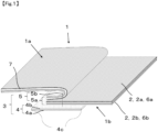
- Fig. 1 is a cross-sectional view of a part including a joint region 3 of cloth 1 according to Embodiment 1 of the present invention.
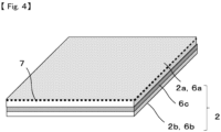
- Fig. 4 is a cross-sectional view of a part of a layered nonwoven fabric 2.
- Fig. 5 is a cross-sectional view of a part of a tape member 4.
- Fig. 6 is a perspective view from an outer side 1a of the cloth 1 shown in Fig. 1 .
- Fig. 7 is an exploded view of the cloth 1 shown in Fig. 6 .
- the cloth 1 according to Embodiment 1 of the present invention includes the layered nonwoven fabric 2, the tape member 4 in a rectangular shape, and the joint region 3.
- an inner side of the cloth means a wearer side when the cloth is worn
- an outer side of the cloth means an opposite side of the inner side of the cloth.
- the layered nonwoven fabric 2 has a first outermost layer 2a and a second outermost layer 2b, the first outermost layer 2a is located on the outer side 1a of the cloth 1, and the second outermost layer 2b is located on an inner side 1b of the cloth 1.
- the layered nonwoven fabric 2 is cut into parts for each part of the cloth 1, and the parts are joined at the joint region 3 to form the cloth 1.
- the joint region 3 includes a seam allowance 5 and the tape member 4. Further, the seam allowance 5 has a layered region 5a in which a part of one or more layered nonwoven fabrics 2 is layered, and this layered region 5a further has at least one of a sewn region and a fused region 5b (in the present application, hereinafter, "at least one of a sewn region and a fused region” may be referred to as a "sewn region and the like").
- the layered region 5a here refers to a minimum distance side from at least one of the sewn region and the fused region 5b (in the present application, hereinafter, "at least one of the sewn region and the fused region” may be referred to as the "sewn region and the like") to a cut edge in a region where one or more layered nonwoven fabrics 2 are overlapped.
- examples of the form of the layered region include the following.
- a part of the layered nonwoven fabric is both end portions of the layered nonwoven fabric in a longitudinal direction, and both end portions overlap to form a layered region.
- the layered nonwoven fabric has a tubular shape.
- one end portion of one layered nonwoven fabric and one end portion of the other layered nonwoven fabric overlap to form a layered region.
- a means for forming the sewn region there is sewing with a sewing machine or sewing by hand, but sewing with a sewing machine is preferable from a viewpoint of productivity.
- a method of sewing with a sewing machine a method such as lock stitch, overlock, catch stitch, double chain stitch, or flat stitch is preferably used, but any of them may be used, and more preferably, as shown in Fig. 1 , the lock stitch is used because it is linear, has a small exposed area and thickness, and is excellent in texture and strength.
- fusion by any process of ultrasonic heating, high frequency heating, and resistance heating is preferably used, but any of them may be used, and more preferably, an ultrasonic processing method is used because of its excellent quality stability and productivity.
- the first outermost layer 2a of the layered nonwoven fabric 2 located on the outer side 1a of the cloth 1 contains 0.02 to 0.50% by mass of an antistatic agent 7 relative to the entire layer.
- the first outermost layer 2a is located on the outer side 1a of the cloth 1, electrostatic charge of the surface of the outer side 1a of the cloth 1 is suppressed. Accordingly, adhesion of dust in an outside air environment to the outer side 1a of the cloth 1 is suppressed, and as a result, the dust protection of the cloth 1 is excellent.
- the content of the antistatic agent in the first outermost layer is based on the entire first outermost layer.
- the dust protection of the cloth 1 is not improved even if electrostatic charge of the surface of the inner side 1b of the cloth 1 is suppressed and adhesion of dust to the surface of the inner side 1b of the cloth 1 is suppressed.
- the content of the antistatic agent in the second outermost layer is 0.01% by mass, and the second outermost layer does not contain an antistatic agent or contains an extremely small amount of the antistatic agent because the cloth is excellent in liquid protection. Note that, the content of the antistatic agent in the second outermost layer is based on the entire second outermost layer.
- Dust floating in the air is usually charged with positive or negative static electricity and is in a charged state. Due to the electrostatic charge of the dust approaching the cloth 1, electricity of opposite polarity is attracted to the surface of the cloth 1, and electrostatic induction occurs. When electrostatic induction occurs, a Coulomb force acts between the dust and the cloth 1, and the dust is attracted and adhered to the cloth 1.
- the antistatic agent 7 in order to suppress adhesion of charged dust to the surface of the cloth 1 due to electrostatic induction, it is preferable to apply the antistatic agent 7 to the first outermost layer 2a of the layered nonwoven fabric 2 located on a side where the dust and the cloth 1 are in contact with each other, that is, on the outer side 1a of the cloth 1 within the above preferable range.
- the content of the antistatic agent 7 is less than 0.02% by mass, there is a problem that an antistatic effect cannot be sufficiently obtained and the dust protection is inferior, and on the contrary, when the content is 0.50% by mass or more, hydrophilicity of a fiber surface increases and the water pressure resistance decreases. More preferably, the content is in the range of 0.20 to 0.50% by mass.
- the antistatic effect that is, the dust protection of such a layered nonwoven fabric 2 can be measured using the first outermost layer 2a of the layered nonwoven fabric 2 as a measurement surface based on the EN 1149-1-2006 surface resistance.
- a preferable range of the surface resistance in the cloth 1 of the present invention is 2.5 ⁇ 10 9 ⁇ or less. When the surface resistance exceeds 2.5 ⁇ 10 9 ⁇ , the antistatic effect is not sufficiently obtained, and the dust protection is inferior. More preferably, the surface electric resistance value is in the range of 1.5 ⁇ 10 9 or less.
- Examples of the type of the antistatic agent 7 include a cationic antistatic agent, an amphoteric antistatic agent, and an anionic antistatic agent. Then, a quaternary ammonium salt compound and an acetate compound of an aliphatic amine correspond to the cationic antistatic agent, a betaine compound, a carboxymethyl amine compound, and an imidazolium compound correspond to the amphoteric antistatic agent, and a sulfate compound, a sulfonic acid compound, and a phosphate compound correspond to the anionic antistatic agent.
- an anionic antistatic agent is more preferable, and a phosphoric acid ester compound is still more preferable from a viewpoint of being able to lower surface electric resistance, which is an index of antistatic performance.
- a processing method of the antistatic agent 7 may be any of a method of immersing the fibers of the first outermost layer 2a of the layered nonwoven fabric 2 in a treatment liquid containing the antistatic agent 7, a method of kneading the antistatic agent 7 into the fibers of the first outermost layer 2a of the layered nonwoven fabric 2 to perform an antistatic treatment on the fibers themselves, a method coating the fibers of the first outermost layer 2a of the layered nonwoven fabric 2 with a coating agent containing the antistatic agent 7 to perform an antistatic treatment, and the like.
- immersion treatment is preferable because an amount of adhesion is easy to control, providing excellent productivity.
- An agent adhesion rate of the antistatic agent 7 to the layered nonwoven fabric is determined by the following method. That is, as a first procedure, a layer other than the first outermost layer 2a of the layered nonwoven fabric is removed using No. 1000 sandpaper, the obtained first outermost layer 2a of the layered nonwoven fabric is cut out to a size of 15 cm ⁇ 15 cm, and a weight of the obtained first outermost layer 2a of the layered nonwoven fabric is measured to the fifth decimal place in a unit of gram.
- the first outermost layer 2a of the layered nonwoven fabric whose weight has been measured is put into a beaker containing 100 ml of methanol, and extraction with ultrasonic waves is performed for ten minutes.
- the extract obtained by ultrasonic washing is dried at 40°C, concentrated to 1 ml, and then filtered with a 0.45 ⁇ m PTFE disk filter, and the obtained extract filtrate is diluted 10 times, and then measured by LC/MS/MS, LC20A manufactured by SHIMADZU CORPORATION.
- the antistatic agent used is identified from the obtained result, and an area of a peak portion corresponding to the identified antistatic agent is calculated.
- the same composition as the antistatic agent identified from the first outermost layer 2a of the layered nonwoven fabric is newly prepared, a 10 fold diluted solution, a 100 fold diluted solution, and a 1000 fold diluted solution are prepared with methanol, respectively, and measurement is performed in the same manner as in the extraction filtrate.
- a peak area corresponding to the identified antistatic agent is calculated, and a calibration curve of the identified amount of the antistatic agent and the obtained peak area is prepared. The obtained peak area is compared with the calibration curve, and the amount of the antistatic agent adhered to the first outermost layer 2a of the layered nonwoven fabric is calculated.
- a value obtained by dividing the amount of the antistatic agent adhered to the first outermost layer 2a of the layered nonwoven fabric by the weight of the first outermost layer 2a of the layered nonwoven fabric measured in advance is rounded off to the first decimal place to obtain an agent adhesion rate (% by mass) of the antistatic agent 7.
- the joint region 3 of the cloth 1 of the present invention has the seam allowance 5 located on the inner side 1b of the cloth in that the outer side 1a of the cloth 1 has a flat shape and dust adhesion and catching on an object in contact with the cloth 1 are suppressed.
- a method of processing in a state where the surfaces of the outer sides 1a of the cloth 1 of a plurality of parts to be joined are in contact with each other, that is, in a state where the first outermost layers 2a of the layered nonwoven fabric 2 are in contact with each other is preferably used.
- the seam allowance 5 of the joint region 3 is covered with the tape member 4 in terms of liquid protection by blocking an entry path of a liquid material existing in the outside air environment from the seam allowance 5.
- the entry path of the liquid material adhered to the outer side 1a of the cloth 1 to the inner side 1b of the cloth 1 includes a path that first reaches the sewn region and the like 5b of the seam allowance 5 and then reaches the end portion of the seam allowance, or a path that reaches the outermost layer of the layered nonwoven fabric 2 through the sewn region and the like 5b of the seam allowance 5.
- the tape member 4 covers the seam allowance 5 to suppress entry of the liquid material from the path into the cloth 1.
- a method is preferably used in which the tape member 4 is disposed on the seam allowance 5 of the joint region 3 and adhesion processing is performed.
- hot air heating, resistance heating, high frequency heating, ultrasonic heating and the like are mainly preferably used, but any of them may be used, and more preferably, the hot air heating method is used because it is excellent in productivity and followability to the joint region 3 having a curve.
- the seam allowance 5 is located on the inner side of the cloth, and the tape member 4 is also located on the inner side 1b of the cloth 1. Accordingly, the number of members on which dust can accumulate outside the outer side 1a of the cloth 1 is reduced, and as a result, the cloth is excellent in dust protection. Further, when the tape member 4 is located on the inner side 1b of the cloth, an adhesive resin layer 4b of the tape member 4 comes into contact with the second outermost layer of the layered nonwoven fabric that is the fabric of the cloth.
- this second outermost layer does not contain an antistatic agent or contains an extremely small amount of the antistatic agent, the second outermost layer has high affinity with the above-mentioned adhesive resin layer 4b, and the tape member 4 and the layered nonwoven fabric 2 are firmly fixed, as a result, a liquid protection performance of the joint region is selected.
- the antistatic agent contained in the first outermost layer makes it difficult for the tape member 4 to adhere to the layered nonwoven fabric that is the fabric of the cloth, and as a result, the liquid protection of the cloth tends to be inferior.
- a method is preferably used in which the inner side 1b of the cloth 1, that is, the second outermost layer 2b of the layered nonwoven fabric 2 and the tape member 4 are made to face each other and adhesion processing is performed.
- a method is preferably used in which a dimension of the tape member 4 in the short-side direction is designed to exceeds a minimum dimension from the sewn region 5b of the seam allowance 5 to the end portion of the layered region 5a.
- the minimum distance from one end portion of the tape member 4 in the short-side direction to the end portion of the layered region 5a of the seam allowance 5 is defined as a first dimension
- the minimum distance from the other end portion of the tape member 4 in the short-side direction to the sewn region and the like 5b of the seam allowance 5 is defined as a second dimension
- a method is preferable in which the tape member 4 is disposed so that the first dimension and the second dimension are equal to each other. This is because the entry path of the liquid material can be uniformly covered, and a bias of liquid protection is reduced.
- an opening for putting on and taking off the cloth in which the layered nonwoven fabric 2 and a fastener are joined and a pocket for storage can be provided separately from the joint region 3.
- the seam allowance 5 at the position has the layered region 5a of the layered nonwoven fabric 2 and a secondary material, there are a plurality of interlayer boundaries of the seam allowance 5, and the entry path of the liquid material is diverse, therefore, it may be necessary to add the position of the tape member 4 or change the position.
- the content of the antistatic agent 7 in the second outermost layer 2b of the layered nonwoven fabric 2 located on the inner side 1b of the cloth 1 is 0.01% by mass or less relative to the entire second outermost layer from a viewpoint of adhesiveness between the layer and the tape member 4.
- the second outermost layer does not contain an antistatic agent, or contains an extremely small amount of the antistatic agent.
- the content of the antistatic agent exceeds 0.01% by mass, such as when the content of the antistatic agent in the second outermost layer is 0.02% by mass, the adhesiveness between the second outermost layer and the tape member 4 is lowered, and the liquid protection of the cloth is inferior.
- the same means as the processing of the first outermost layer 2a of the layered nonwoven fabric 2 can be used.
- the layered nonwoven fabric 2 constituting the cloth 1 of the present invention has a water pressure resistance in the range of 1,000 mmH 2 O to 1,0000 mmH 2 O as measured according to JIS L 1092 (2009) A method, which is preferable because the cloth 1 has excellent liquid protection.
- the water pressure resistance is less than 1,000 mmH 2 O, the liquid material tends to enter from the layered nonwoven fabric 2 when the cloth 1 is worn, resulting in inferior liquid protection.
- the water pressure resistance exceeds 1,0000 mmH 2 O, a temperature inside the cloth 1 tends to rise due to sealing properties of the layered nonwoven fabric 2, resulting in inferior comfort.
- the water pressure resistance is in the range of 1000 mmH 2 O to 4000 mmH 2 O.
- the ratio of the water pressure resistance (A) of the layered nonwoven fabric 2 to the water pressure resistance (B) of the joint region 3 is preferably 0.4 to 1.0 from a viewpoint that the water pressure resistance of the layered nonwoven fabric 2 and the joint region 3 is balanced and stability of liquid protection as the cloth 1 is excellent.
- the ratio is less than 0.4 or more than 1, the pressure of liquid invasion is concentrated on the side of the layered nonwoven fabric 2 or the joint region 3 where the water pressure resistance is low, and local contamination tends to occur, resulting in inferior liquid protection. More preferably, the ratio is in the range of 0.6 to 1.0.
- the ratio of the water pressure resistance (A) of the layered nonwoven fabric 2 to the water pressure resistance (B) of the joint region 3 there is a method of selecting the tape member 4 having a configuration that has a water pressure resistance equivalent to that of the layered nonwoven fabric 2, or a method of adjusting adhesion of both end portions of the tape member 4 in the short-side direction fixed to the second outermost layer 2b of the layered nonwoven fabric 2 by adhesion conditions. Any one of them may be used, but a combination of these means is more preferable.
- Examples of the material of the fibers constituting the first outermost layer 2a of the layered nonwoven fabric 2 and the second outermost layer 2b of the layered nonwoven fabric 2 include a polyolefin-based resin (for example, polyethylene, polypropylene, a copolymer of ethylene and ⁇ -olefin, a copolymer of propylene and ⁇ -olefin, and the like), a styrene-based resin (for example, polystyrene, acrylonitrile styrene resin, and the like), a polyetherbased resin (for example, polyether ether ketone, polyacetal, modified polyphenylene ether, aromatic polyether ketone, and the like), a polyester-based resin (for example, polyethylene terephthalate, polytrimethylene terephthalate, polybutylene terephthalate, polyethylene naphthalate, polybutylene naphthalate, polycarbonate, polyarylate, aromatic polyester resin, and
- the polyolefin-based resin is preferable from a viewpoint of excellent productivity and texture of the layered nonwoven fabric 2.
- polyethylene and polypropylene are particularly preferable because they have low moisture-absorption properties, are excellent in skin separation of the fabric to the skin surface after sweating, and can provide greater comfort during work.
- the cloth 1 of the present invention can be used by directly layering the fibers of the first outermost layer 2a of the layered nonwoven fabric 2 and the fibers of the second outermost layer 2b of the layered nonwoven fabric 2.
- Examples of the structure of the layered nonwoven fabric 2 include a lamination layer of one or more nonwoven fabrics selected from the group consisting of a spun lace nonwoven, a spunbond nonwoven, a meltblown nonwoven 6c, and a needle punch nonwoven. Among these, it is preferable to layer a spunbond nonwoven having high productivity and high strength and air permeability and a meltblown nonwoven 6c having high water pressure resistance.
- a first spunbond nonwoven 6a, a meltblown nonwoven 6c, and a second spunbond nonwoven 6b are provided in this order, which provides excellent strength, productivity, and cost, and also make it easier to obtain the preferable water pressure resistance of the layered nonwoven fabric 2.
- the first spunbond nonwoven 6a herein corresponds to the first outermost layer 2a of the layered nonwoven fabric 2
- the second spunbond nonwoven 6b corresponds to the second outermost layer 2b of the layered nonwoven fabric 2.
- the basis weight of the first spunbond nonwoven 6a is preferably 20 to 50 g/m 2 because this makes it easier to set the amount of adhesion of the antistatic agent 7 to the first outermost layer 2a of the layered nonwoven fabric 2 within the preferable range. In a case where the basis weight of the first spunbond nonwoven 6a is less than 20 g/m 2 , the antistatic agent 7 in the first outermost layer 2a of the layered nonwoven fabric 2 is less likely to adhere, resulting in inferior dust protection. In a case where the basis weight exceeds 50 g/m 2 , the weight of the cloth 1 increases. More preferably, the basis weight is in the range of 25 to 40 g/m 2 .
- the basis weight of the second spunbond nonwoven 6b is 5 to 30 g/m 2 , which makes it easier to set the amount of adhesion of the antistatic agent 7 to the second outermost layer 2b of the layered nonwoven fabric 2 within the preferable range. In addition, it is preferable because both end portions of the tape member 4 in the short-side direction can easily fixed to the second outermost layer 2b of the layered nonwoven fabric 2. When the basis weight of the second spunbond nonwoven 6b is 5 g/m 2 or more, the strength is excellent.
- the basis weight is 30 g/m 2 or less, the tape member 4 and the second outermost layer 2b of the layered nonwoven fabric 2 can be easily adhered to each other, and the water pressure resistance can be easily obtained at the joint region 3, that is, the liquid protection is excellent. More preferably, the basis weight is in the range of 10 to 25 g/m 2 .
- the basis weight of the second spunbond nonwoven 6b is smaller than the basis weight of the first spunbond nonwoven 6a because both end portions of the tape member 4 in the short-side direction can be easily fixed to the second outermost layer 2b of the layered nonwoven fabric 2, which is a side with a lower basis weight, and the water pressure resistance of the joint region 3 is excellent.
- the antistatic agent 7 in the first outermost layer 2a of the layered nonwoven fabric 2 can be easily adhered, providing excellent dust protection. Furthermore, the adhesion between the tape member 4 and the second outermost layer 2b of the layered nonwoven fabric 2 is increased, and the water pressure resistance of the joint region 3 can be easily obtained, that is, the liquid protection is excellent.
- the tape member 4 is a layered body including a base material layer and an adhesive resin layer, which makes it easier to fix both end portions of the tape member 4 in the short-side direction to the second outermost layer 2b of the layered nonwoven fabric 2 due to impregnation and permeability of the adhesive resin layer 4b of the tape member 4.
- a base material layer 4a of the tape member 4 serves as a waterproof layer, the water pressure resistance, that is, the liquid protection of the joint region 3, can be easily increased.
- the material of the base material layer it is preferable to mainly use a fiber woven or knitted fabric, a nonwoven fabric, a film alone, or a layered body, because they are excellent in flexibility. More preferably, the material is a film or a high-density woven fabric, which makes it difficult for the thickness to be visually recognized and provides excellent appearance quality.
- the thickness of the adhesive resin layer 4b of the tape member 4 is 10 to 200 ⁇ m and the adhesive resin layer is in contact with the second outermost layer, which makes it easier to seal and close a step formed by the seam allowance 5 located on the side of the second outermost layer of the layered nonwoven fabric 2 and the layered region 5a of the layered nonwoven fabric 2 in the joint region 3.
- the joint region 3 has excellent water pressure resistance, that is, excellent liquid protection.
- the thickness of the adhesive resin layer is 10 ⁇ m or more, a gap can be easily filled between the tape member 4 and the seam allowance 5, that is, the step of the layered region 5a of the layered nonwoven fabric 2, and the water pressure resistance can be easily obtained at the joint region 3, that is, the liquid protection is excellent.
- the thickness of the adhesive resin layer is 200 ⁇ m or less, the thickness of the adhesive resin layer is small, the joint region 3 can be easily softened, and the adhesive resin is less likely to protrude around the tape member 4 and the seam allowance 5, that is, the layered region 5a of the layered nonwoven fabric 2, providing excellent appearance quality. More preferably, the thickness is in the range of 30 to 100 ⁇ m.
- the thickness of such a bonded region was measured according to JIS K 7130: 1999 plastic-film and sheetthickness measurement method.
- any method may be used, such as various molding methods such as T-die, injection, and inflation, and coating methods such as knife over coating and gravure.
- T-die molding is preferable in terms of adaptive thickness, shape, and the like.
- a coating method or a lamination method is preferably used as a means for forming the adhesive resin layer.
- the coating method may be any method as long as it is a method for forming a film, such as a method in which a resin is dry-bonded to the base material layer or wetsolidified.
- silica addition, dry foaming by addition of a foaming agent, formation of microporous polyurethane by wet-coagulation, provision of irregularities with an embossing roller, and the like can be used in order to adjust the coefficient of static friction or to reduce the weight.
- Titanium oxide, carbon black, a pigment, an antioxidant, an ultraviolet absorber, a light stabilizer, a flame retardant, and the like may be appropriately contained in the resin film.
- an organic adhesive is mainly used, and the type of the organic adhesive is roughly classified into a natural resin-based adhesive such as natural rubber casein, a semi-synthetic-based adhesive such as cellulose acetate, and a synthetic resin-based adhesive using polyolefin, polyurethane, acrylic, or the like.
- a synthetic resin-based adhesive is preferable in terms of workability and cost.
- Resin components of the synthetic resin-based adhesive is subdivided into a resin-based component using polyurethane, polyester, PVA, vinyl chloride, an acrylic resin, polyethylene, an ethylene-vinyl acetate polymer, a polyamide-based resin, a polyolefin-based resin, and the like, an elastomer-based component using silicone rubber, nitrile rubber, and the like, and a composite-based component such as nylon epoxy, vinyl phenolic, and the like. More preferably, the polyolefin-based component is preferable because it has high workability and has excellent heat resistance, adhesive strength, and durability due to a cross-linking reaction with moisture (moisture) contained in the air.
- Solidification and reaction forms of the synthetic resin-based adhesive includes a dry solidification type such as a water-soluble type, a latex type, and a dispersion type, a chemical reaction type in which a crosslinking reaction occurs by mixing a main agent and a curing agent, and curing is performed, a heat melting type in which the adhesive is solid at room temperature, but melted by heating, and fixed when cooled, a pressure sensitive type in which a high viscosity fluid liquid is pressurized to create an adhesive, and a moisture-curing type in which the adhesive is cured by reacting with moisture in the air.
- a dry solidification type such as a water-soluble type, a latex type, and a dispersion type
- a chemical reaction type in which a crosslinking reaction occurs by mixing a main agent and a curing agent, and curing is performed
- a heat melting type in which the adhesive is solid at room temperature, but melted by heating, and fixed when cooled
- a pressure sensitive type in which a
- the heat melting type thermoplastic hot melt
- the moisture-curing type are preferable because they have excellent adhesive strength at a boundary surface between the adhesive resin layer and the second outermost layer 2b of the layered nonwoven fabric 2.
- the layered nonwoven fabric 2 has an air permeability of 2.0 to 40.0 cm 3 /cm 2 /sec as measured according to JIS L1913 (2010) 6.8 (Frazier type method) because of excellent air permeability of the cloth 1.
- the air permeability is 2.0cm 3 /cm 2 /sec or more, the temperature inside the cloth 1 is less likely to rise when the cloth 1 is worn, providing excellent air permeability, and when the air permeability is 40.0cm 3 /cm 2 /sec or less, mist-like scattered matters is less likely to flow in from the layered nonwoven fabric 2, providing excellent protective properties. More preferably, the air permeability is in the range of 4.0 to 20.0 cm 3 /cm 2 /sec.
- any method may be used, such as a method of adjusting the fiber diameter, basis weight, or density of the layered nonwoven fabric 2, and a method of changing these for each layer of the layered nonwoven fabric 2.
- the method of adjusting the basis weight of the layered nonwoven fabric 2 is preferable from a viewpoint of being able to achieve both the dust protection and the liquid protection. More preferably, the basis weight is set to be within the preferred range of the basis weight of the first spunbond nonwoven 6a and the second spunbond nonwoven 6b described above.
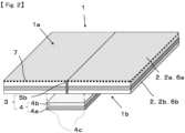
- Fig. 2 is a cross-sectional view of the cloth 1 according to Embodiment 2 of the present invention.
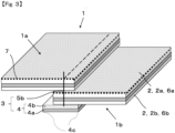
- Fig. 3 is a cross-sectional view of cloth 1 according to a modification of Embodiment 2 of the present invention.
- Fig. 6 is a perspective view from an outer side 1a of the cloth 1 shown in Fig. 1 .
- Fig. 7 is an exploded view of the cloth 1 shown in Fig. 6 .
- the cloth 1 according to Embodiment 2 of the present invention is composed of a layered nonwoven fabric 2 and members including a tape member 4 in a rectangular shape, and further includes a joint region 3.
- a layered nonwoven fabric 2 Similar to Embodiment 1, the cloth 1 according to Embodiment 2 of the present invention is composed of a layered nonwoven fabric 2 and members including a tape member 4 in a rectangular shape, and further includes a joint region 3.
- main differences between the cloth 1 according to the Embodiment 2 and the cloth 1 according to Embodiment 1 will be described.
- the layered nonwoven fabric 2 is cut into parts for each part of the cloth 1, and the parts are joined at the joint region 3 to form the cloth 1.
- This joint region 3 is composed of at least one of a sewn region and a fused region 5b, and the tape member 4.
- the joint region 3 is different from the sewn region included in the cloth of Embodiment 1, in at least one of the sewn region and the fused region described above, surfaces horizontal to the thickness direction at two end portions of at least one layered nonwoven fabric face each other.
- the joint region 3 in the Embodiment 2 does not have a seam allowance 5 having a layered region 5a in which a part of the layered nonwoven fabric 2 is layered, as in the cloth of Embodiment 1.
- both end portions of one layered nonwoven fabric for example, in a case where the layered nonwoven fabric has a rectangular shape, both end portions in the longitudinal direction can be exemplified, and in a state where surfaces horizontal to the thickness direction at the both end portions face each other, this layered nonwoven fabric becomes a tubular shape.
- two end portions of two layered nonwoven fabrics for example, in a case where the two layered nonwoven fabrics are both in a rectangular shape, one end portion of one layered nonwoven fabric and one end portion of the other layered nonwoven fabric can be exemplified, and surfaces horizontal to the thickness direction of these two end portions face each other.
- the surface horizontal to the thickness direction of the layered nonwoven fabric is a concept that includes a surface substantially horizontal to the thickness direction, and is also a concept that includes common sense as a cut surface of the layered nonwoven fabric.
- the joint region 3 is formed by butting the end portions of the parts of the layered nonwoven fabric 2 together, forming a sewn region by stitching or a fused region by fusion on the butted region, and covering the sewn region and the like 5b with the tape member 4.
- the tape member is located on the inner side of the cloth.
- the reason for this is similar to the description of the cloth of Embodiment 1.
- the first outermost layer needs to contain an antistatic agent in a specific content for the reason of making the dust protection of the cloth excellent.
- the second outermost layer does not contain an antistatic agent or contains an extremely small amount of the antistatic agent for the reason that the second outermost layer is excellent in adhesion to the tape member while it is not found necessary to suppress charging. Therefore, when the tape member is located on the inner side of the cloth, the adhesive resin layer of the tape member inevitably comes into contact with the second outermost layer, and the layered nonwoven fabric and the tape member are firmly fixed.
- the entry path of the liquid material into the cloth 1 in the present embodiment includes a path through which the liquid material enters from a sewn region or a fused region between the parts of the layered nonwoven fabric 2 butted with each other.
- the tape member 4 covers the sewn region and the like 5b to suppress entry of the liquid material from the path into the cloth 1.
- the joint region 3 is formed by partially overlapping a part of the parts of the layered nonwoven fabric 2 in parallel, forming a sewn region by stitching or a fused region by fusion in the overlapped region, and covering the sewn region and the like 5b with the tape member 4.
- the entry path of the liquid material into the cloth 1 in the present embodiment includes, as a first path, a path through which the liquid material enters from the sewn region or the fused region on the side of the layered nonwoven fabric 2 located on an upper side of the parts of the layered nonwoven fabric 2 overlapped each other, that is, on an outermost side of the cloth 1, and reaches the sewn region or the fused region on the side of the layered nonwoven fabric 2 located on a lower side of the parts of the layered nonwoven fabric 2, that is, on an innermost side of the cloth 1 through the sewn region or the fused region.
- the tape member 4 covers the sewn region and the like 5b to suppress entry of the liquid material from the path into the cloth 1.
- Embodiment 2 of the cloth of the present invention may be similar to Embodiment 1 except for the above difference.
- test pieces of 200 mm ⁇ 200 mm were collected from each of the first outermost layer 2a of the layered nonwoven fabric and the second outermost layer 2b of the layered nonwoven fabric, the mass of each test piece was measured to determine the mass per unit area, and an average value of each test piece was used.
- the unit was g/m 2 .
- the water pressure resistance of the layered nonwoven fabric 2 and the joint region 3 was measured by applying water pressure to the test piece at a pressure rising rate of 60 cm/min according to JIS L1092-2009 low water pressure resistance method, measuring the water pressure at a point of time when three drops of water were discharged, and using the average value of three measurements.
- the unit was mmH 2 O.
- the ratio of the water pressure resistance (A) of the layered nonwoven fabric to the water pressure resistance (B) of the joint region measured in the previous paragraph was calculated by the following equation (water pressure resistance (B) ⁇ water pressure resistance (A)), and the value was set to two decimal places.
- the content of the antistatic agent with respect to the first outermost layer 2a of the layered nonwoven fabric and the content of the antistatic agent with respect to the second outermost layer 2b of the layered nonwoven fabric were determined for each layer by the following procedure.
- a layer other than the first outermost layer 2a of the layered nonwoven fabric was removed using No. 1000 sandpaper, the obtained first outermost layer 2a of the layered nonwoven fabric was cut out to a size of 15 cm ⁇ 15 cm, and the weight of the obtained first outermost layer 2a of the layered nonwoven fabric was measured to the fifth decimal place in the unit of gram.
- the first outermost layer 2a of the layered nonwoven fabric whose weight had been measured was put into a beaker containing 100 ml of methanol, and extraction with ultrasonic waves was performed for ten minutes.
- the extract obtained by ultrasonic washing was dried at 40°C, concentrated to 1 ml, and then filtered with a 0.45 ⁇ m PTFE disk filter, and the obtained extract filtrate was diluted 10 times, and then measured by LC/MS/MS, LC20A manufactured by SHIMADZU CORPORATION. From the obtained result, the antistatic agent used was identified, and the areas of the peak portion corresponding to the identified antistatic agent was calculated.
- the same composition as the antistatic agent identified from the first outermost layer 2a of the layered nonwoven fabric was newly prepared, a 10 fold diluted solution, a 100 fold diluted solution, and a 1000 fold diluted solution were prepared with methanol, respectively, and measurement was performed in the same manner as in the extraction filtrate.
- a peak area corresponding to the identified antistatic agent was calculated, and a calibration curve of the identified amount of the antistatic agent and the obtained peak area was prepared. The obtained peak area was compared with the calibration curve, and the amount of the antistatic agent adhered to the first outermost layer 2a of the layered nonwoven fabric was calculated.
- a value obtained by dividing the amount of the antistatic agent adhered to the first outermost layer 2a of the layered nonwoven fabric by the weight of the first outermost layer 2a of the layered nonwoven fabric measured in advance was rounded off to the first decimal place, and this was used as the content of the antistatic agent in the first outermost layer 2a of the layered nonwoven fabric.
- the unit was % by mass.
- the content of the antistatic agent was calculated in the same manner as described above.
- the surface electric resistance of an antistatic dust protective fabric was measured using a surface resistance obtained from a test piece having a size of 12 cm ⁇ 12 cm according to EN1149-1-2006, using the first outermost layer 2a of the layered nonwoven fabric as a measurement surface.
- the unit was ⁇ .
- the thickness of the adhesive resin layer 4b of the tape member was determined as follows: a cross section of the tape member 4 was cut out, a platinum-palladium alloy was deposited on the cross section, the entire thickness of the tape member 4 was measured from an image taken by a scanning electron microscope (SEM) (Model S-4000 manufactured by Hitachi, Ltd.), the thickness of the base material layer 4a of the tape member was then measured, the thickness of the base material layer was subtracted from the previously obtained entire thickness of the tape member 4, and the subtracted value was defined as the thickness of the adhesive resin layer 4b of the tape member. The unit was ⁇ m.
- the air permeability of the layered nonwoven fabric 2 was measured as the amount of air passing through a test piece having a size of 15 cm ⁇ 15 cm according to JIS L 1913-2010 Frazier type method. The average value of the obtained three measurements of the amount of air passing through was used. The unit was cm 3 /cm 2 /sec, and was valid up to the first decimal place.
- the liquid protection of a body part of the cloth, that is, the layered nonwoven fabric 2 was evaluated according to criteria in Table 1. The higher the parameter score, the better the liquid protection.
- the liquid protection of a joint position between the parts of the cloth, that is, the joint region 3 was evaluated according to the criteria in Table 1. The higher the parameter score, the better the liquid protection.
- the dust protection of the cloth was evaluated according to the criteria in Table 1. The higher the parameter score, the better the dust protection.
- the cloth shown in Figs. 1 and 4 to 7 that is, as a configuration of the layered nonwoven fabric 2, a polypropylene spunbond nonwoven having a basis weight of 45 g/m 2 was used, a mangle treatment was performed using a solution obtained by mixing an anionic antistatic agent in pure water as the antistatic agent 7, a coating amount of the antistatic agent 7 was adjusted to 0.135 g/m 2 , and coating was performed so that the content of the antistatic agent was 0.3% by mass.
- the polypropylene spunbond nonwoven after the mangle treatment was dried at 135°C for one minute with a pin tenter, and this was used as the second outermost layer 2a of the layered nonwoven fabric 2.
- the content of the antistatic agent was set to 0% by mass, and this was used as the second outermost layer 2b of the layered nonwoven fabric 2.
- a polypropylene meltblown nonwoven 6c having an average fiber diameter of 1.6 ⁇ m and a basis weight of 15 g/m 2 was used as an intermediate layer of the layered nonwoven fabric 2.
- the obtained first outermost layer 2a, the intermediate layer, and the second outermost layer 2b of the layered nonwoven fabric were layered in this order, and layered and integrated in an embossing device under the conditions of a temperature of 120°C, a pressure of 60 kg/m 2 , and a speed of 10 m/min to obtain a layered nonwoven fabric 2.
- a resin mainly composed of a polyolefin-based thermoplastic hot melt resin that is, a polyolefin-based resin having hot melt adhesiveness and a melting point temperature of 85°C was used.
- the resin was discharged and stretched in a sheet shape onto release paper by an extrusion method so as to have a film thickness of 150 ⁇ m, a stress at 50% elongation of 3.4 MPa, and a breaking strength of 26.7 MPa, and then separated from the release paper to obtain an adhesive resin layer, which was used as the adhesive resin layer 4b of the tape member 4.
- a film was obtained in which a resin mainly composed of a polypropylene resin having a softening point of 60°C and a melting point of 115°C was used as a raw material, and the film was discharged and stretched in a sheet shape so as to have a film thickness of 50 ⁇ m, a stress at 50% elongation of 0.5 MPa, and a breaking strength of 26 MPa.
- the adhesive resin layer 4b was layered on the obtained base material layer 4a of the tape member 4 to obtain a tape member 4 consisting of the base material layer 4a and the adhesive resin layer 4b.
- the tape member 4 was formed by slit molding so that a width of the tape member 4, that is, the dimension between the end portions 4c in the short-side direction was 22 mm.
- the layered nonwoven fabric 2 was cut into a part shape of the cloth shown in Figs. 6 to 7 , and the cut parts were sewn together with a sewing machine to form a seam allowance 5 consisting of the sewn region 5b and the layered region 5a. Note that, an exposure direction of the seam allowance 5 was set to the inner side of the cloth 1.
- the tape member 4 was disposed on the inner side of the cloth, the seam allowance 5 was covered with the adhesive resin layer 4b of the tape member 4, and adhesion processing was performed using a hot air heating type heat sealer under the conditions of a roller portion heating temperature of 90°C, a pressure of 0.4 MPa, and a speed of 2 m/min. Both the end portions 4c of the tape member 4 in the short-side direction were fixed in contact with the second outermost layer 2b of the layered nonwoven fabric 2, and the tape member 4 extended along the longitudinal direction of the seam allowance 5 to form the joint region 3 having the tape member 4 in a rectangular shape, thereby obtaining cloth 1.
- the water pressure resistance of the layered nonwoven fabric 2 of the obtained cloth 1, the ratio of the water pressure resistance between the joint region 3 and the layered nonwoven fabric 2, the content of the antistatic agent 7, the surface electric resistance, the air permeability, and the thickness 4d of the adhesive resin layer of the tape member 4 were measured, respectively.
- the coating amount of the antistatic agent 7 on the first outermost layer 2a of the layered nonwoven fabric 2 was 0.135 g/m 2 , so that the content of the antistatic agent was 0.3% by mass, and the coating amount of the antistatic agent 7 on the second outermost layer 2b of the layered nonwoven fabric 2 was 0 g/m 2 , so that the content of the antistatic agent was 0% by mass.
- the adhesive resin layer 4b of the tape member 4 had a film thickness of 40 um.
- the layered nonwoven fabric 2 was cut into a part shape of the cloth shown in Figs. 6 to 7 , and the cut parts were fused together by an ultrasonic fusing machine to form a fused region 5b shown in Fig. 2 .
- the tape member 4 was disposed on the inner side of the cloth, the fused region 5b was covered with the adhesive resin layer 4b of the tape member 4, and the same adhesion processing as in Example 1 was performed. Both the end portions 4c of the tape member 4 in the short-side direction were fixed in contact with the second outermost layer 2b of the layered nonwoven fabric 2, and the tape member 4 extended along the longitudinal direction of the fused region 5b to form the joint region 3 having the tape member 4 in a rectangular shape, thereby obtaining cloth 1. Note that, in the joint region 3, the surfaces horizontal to the thickness direction at two end portions of the two layered nonwoven fabrics faced each other in the fused region.
- the cloth 1 was obtained under the same conditions as in Example 1 except for the configurations of the layered nonwoven fabric 2, the joint region 3, and the tape member 4. Numerical values and evaluation results are shown in Table 3.
- the basis weight of the first outermost layer 2a of the layered nonwoven fabric 2 was 25 g/m 2 and the coating amount of the antistatic agent 7 was 0.05 g/m 2 , so that the content of the antistatic agent was 0.2% by mass, and the basis weight of the second outermost layer 2b of the layered nonwoven fabric 2 was 10 g/m 2 and the coating amount of the antistatic agent 7 was 0 g/m 2 , so that the content of the antistatic agent was 0% by mass.
- a polyester taffeta fabric that is, a polyester woven fabric was used in which a plain woven fabric that uses a polyester filament yarn of 33dtex-26f for both warp and weft fibers, and has a warp yarn density of 207 yarns/inch and a weft yarn density of 147 yarns/inch was woven, then relaxed scoured and circular dyed 130°C, dried, and then calendered at 180°C top and 60°C bottom.
- the adhesive resin layer 4b of the tape member 4 had a film thickness of 40 ⁇ m.
- the cloth 1 was obtained under the same conditions as in Example 1 except for the configurations of the layered nonwoven fabric 2 and the tape member 4. Numerical values and evaluation results are shown in Table 3.
- the basis weight of the first outermost layer 2a of the layered nonwoven fabric 2 was 55 g/m 2 and the coating amount of the antistatic agent 7 was 0.0825 g/m 2 , so that the content of the antistatic agent was 0.15% by mass, and the basis weight of the second outermost layer 2b of the layered nonwoven fabric 2 was 35 g/m 2 and the coating amount of the antistatic agent 7 was 0 g/m 2 , so that the content of the antistatic agent was 0% by mass.
- a polypropylene film was used for the base material layer 4a.
- the adhesive resin layer 4b of the tape member 4 had a film thickness of 150 ⁇ m.
- the cloth 1 was obtained under the same conditions as in Example 1 except for the configurations of the layered nonwoven fabric 2 and the tape member 4. Numerical values and evaluation results are shown in Table 3.
- the basis weight of the first outermost layer 2a of the layered nonwoven fabric 2 was 18 g/m 2 and the coating amount of the antistatic agent 7 was 0.081 g/m 2 , so that the content of the antistatic agent was 0.45% by mass, and the basis weight of the second outermost layer 2b of the layered nonwoven fabric 2 was 4 g/m 2 and the coating amount of the antistatic agent 7 was 0 g/m 2 , so that the content of the antistatic agent was 0% by mass.
- a polypropylene film was used for the base material layer 4a.
- the adhesive resin layer 4b of the tape member 4 had a film thickness of 9 ⁇ m.
- the cloth 1 was obtained under the same conditions as in Example 1 except for the configurations of the layered nonwoven fabric 2 and the tape member 4. Numerical values and evaluation results are shown in Table 3.
- the basis weight of the first outermost layer 2a of the layered nonwoven fabric 2 was 55 g/m 2 and the coating amount of the antistatic agent 7 was 0.0825 g/m 2 , so that the content of the antistatic agent was 0.15% by mass, and the basis weight of the second outermost layer 2b of the layered nonwoven fabric 2 was 4 g/m 2 and the coating amount of the antistatic agent 7 was 0 g/m 2 , so that the content of the antistatic agent was 0% by mass.
- a polyethylene microporous film that is, a film made of a polyethylene resin that has physical properties of a thickness of 14 um, a melting point of 137°C, a microporous pore diameter of 32 ⁇ m, a moisture permeability of 380 g/m 2 ⁇ h, a tensile strength (warp) of 40 N/50 mm, a tensile strength (weft) of 40 N/50 mm, a tensile elongation (warp) of 10%, a tensile elongation (weft) of 8%, a water pressure resistance of 65 kPa, and a puncture strength of 370 N/mm was used.
- the adhesive resin layer 4b of the tape member 4 had a film thickness of 250 ⁇ m.
- the cloth 1 was obtained under the same conditions as in Example 1 except for the configurations of the layered nonwoven fabric 2 and the tape member 4. Numerical values and evaluation results are shown in Table 4.
- the sewn region 5b and the layered region 5a were disposed so that the exposure direction of the seam allowance 5 was on the outer side of the cloth 1.
- the tape member 4 was disposed on the outer side of the cloth, the seam allowance 5 was covered with the adhesive resin layer 4b of the tape member 4, and both the end portions 4c of the tape member 4 in the short-side direction were fixed so as to be in contact with the first outermost layer 2a of the layered nonwoven fabric 2 to form the joint region 3.
- the cloth 1 was obtained under the same conditions as in Example 1 except for the configuration of the joint region 3. Numerical values and evaluation results are shown in Table 4.
- the coating amount of the antistatic agent 7 on the first outermost layer 2a of the layered nonwoven fabric 2 was 0.0045 g/m 2 , so that the content of the antistatic agent was 0.01% by mass, and the coating amount of the antistatic agent 7 on the second outermost layer 2b of the layered nonwoven fabric 2 was 0.075 g/m 2 , so that the content of the antistatic agent was 0.3% by mass.
- the cloth 1 was obtained under the same conditions as in Example 1 except for the configuration of the layered nonwoven fabric 2. Numerical values and evaluation results are shown in Table 4.
- the coating amount of the antistatic agent 7 on the first outermost layer 2a of the layered nonwoven fabric 2 was 0.0045 g/m 2 , so that the content of the antistatic agent was 0.01% by mass, and the coating amount of the antistatic agent 7 on the second outermost layer 2b of the layered nonwoven fabric 2 was 0.075 g/m 2 , so that the content of the antistatic agent was 0.3% by mass.
- the joint region 3 did not include the tape member 4, but is formed by sewing the parts obtained by cutting the layered nonwoven fabric 2 together with a sewing machine, with only the seam allowance 5 consist of the sewn region 5b and the layered region 5a.
- the cloth 1 was obtained under the same conditions as in Example 1 except that the configuration of the layered nonwoven fabric 2 and the joint region 3 and the configuration not using the tape member 4 were used. Numerical values and evaluation results are shown in Table 4.
- Example 1 Example 2
- Example 3 Example 9
- Example 5 Configuration Configuration of first outermost layer of layered nonwoven fabric Spunbond nonwoven Spunbond nonwoven Spunbond nonwoven Spunbond nonwoven Spunbond nonwoven Configuration of intermediate layer of layered nonwoven fabric Meltblown nonwoven Meltblown nonwoven Meltblown nonwoven Meltblown nonwoven Meltblown nonwoven Configuration of second outermost layer of layered nonwoven fabric Spunbond nonwoven Spunbond nonwoven Spunbond nonwoven Spunbond nonwoven Spunbond nonwoven Spunbond nonwoven Spunbond nonwoven Base material layer of tape member Polypropylene film Polypropylene film Polyester taffeta Polypropylene film Polypropylene film Adhesive resin layer of tape member Thermoplastic hot melt Thermoplastic hot melt Thermoplastic hot melt Thermoplastic hot melt Thermoplastic hot melt Exposure direction of seam allowance Inner side None Inner side Inner side Inner side Inner side Arrangement position of tape member Inner side Inner side Inner side Inner side Inner side Fixed layers at both end portions of
- the content of the antistatic agent 7 in each of the first outermost layer 2a and the second outermost layer 2b of the layered nonwoven fabric 2 was set within a preferable range, an arrangement of each layer in the cloth and the joint region 3 were set to a preferable aspect, and the water pressure resistance of the layered nonwoven fabric 2 and the ratio of the water pressure resistance of the layered nonwoven fabric 2 to the water pressure resistance of the joint region 3 were set within preferable ranges, so that the cloth was excellent in dust protection and liquid protection.
- the configuration of the tape member 4 and the thickness 4d of the adhesive resin layer 4b were set within preferable ranges, so that the cloth was more excellent in liquid protection at the joint region.
- the cloth of Examples 1 to 3 was cloth having air permeability in addition to dust protection and liquid protection by setting the nonwoven fabric structure and basis weight of each layer of the layered nonwoven fabric 2 within preferred ranges.
- the seam allowance 5 of the joint region 3 and the tape member 4 were disposed on the first outermost layer 2a of the layered nonwoven fabric 2 having a high content of the antistatic agent, that is, on the outer side of the cloth 1, so that the cloth was inferior in liquid protection at the joint region.
- the content of the antistatic agent 7 in the first outermost layer 2a and the second outermost layer 2b of the layered nonwoven fabric 2 and the ratio of the water pressure resistance between the joint region 3 and the layered nonwoven fabric 2 were set to ranges different from the preferable ranges, so that the cloth was inferior in dust protection and liquid protection at the joint region.
- the cloth of Comparative Example 3 further had an aspect in which the tape member was not used for the joint region 3, so that the cloth was inferior in dust protection and liquid protection at the joint region.
- the cloth of Comparative Example 4 further had an aspect in which a single-layer nonwoven fabric was used instead of the layered nonwoven fabric 2, and a tape member was not used, so that the cloth was inferior in all of dust protection, liquid protection of the layered nonwoven fabric, and liquid protection at the joint region.
- the present invention can be used as cloth having dust protection and liquid protection.
Landscapes
- Engineering & Computer Science (AREA)
- Textile Engineering (AREA)
- Mechanical Engineering (AREA)
- Laminated Bodies (AREA)
- Manufacturing Of Multi-Layer Textile Fabrics (AREA)
Abstract
Description
- The present invention relates to cloth.
- Conventionally, various cloth in which a plurality of fabric pieces are joined to each other are commercially available, and as a method of joining these cloth, stitching by sewing with a sewing machine or a method of melting and solidifying overlapped fabric pieces to bond or fuse the fabric pieces are mainly used.
- As cloth in patent documents, cloth in which a hot melt adhesive made of a urethane-based resin, an acrylicbased resin, a silicon-based resin or the like is inserted between overlapped fabric pieces, and the hot melt adhesive is melted and solidified by superheating and pressure bonding to join a plurality of fabric pieces (Patent Document 1) and the like are disclosed.
- As cloth in which liquid protection is imparted to a fabric and a joint region, cloth in which fabric pieces are sewn with a sewing machine or fused using a highly water-resistant and moisture-permeable liquid protective fabric obtained by layering a base fabric and a liquid protective film or a moisture-permeable waterproof film and a sealing tape, and then the fabric pieces are covered with the sealing tape to form a joint region (
Patent Documents - As cloth in which washing durability and sterilization treatment durability are imparted to a fabric and a joint region, cloth in which a polyester fabric is used for a base fabric of the fabric and a polycarbonatebased polyurethane resin is used for a moisture-permeable waterproof film and an adhesive (Patent Document 6) and the like are disclosed.
- As cloth in which liquid protection and fire resistance are imparted to a fabric and a joint region, cloth in which a surface of a fabric obtained by blending heat-resistant flame-retardant fibers is treated with aluminum, fabric pieces are sewn with a sewing machine, and then front and back surfaces of the sewn region are sealed with a flame-retardant waterproof tape (Patent Document 7), a raincoat in which a plurality of multilayer nonwoven fabric pieces are sewn, an antistatic agent is applied to an outer surface, and a sealing tape is sealed to the sewn region (Patent Document 8), and the like are disclosed.
-
- Patent Document 1:
Japanese Patent Laid-open Publication No. 2017-186695 - Patent Document 2: International Publication No.
2007/034837 - Patent Document 3:
Japanese Patent Laid-open Publication No. 2009-183849 - Patent Document 4: International Publication No.
2016/006418 - Patent Document 5: National Publication of International Patent Application No.
2007-508870 - Patent Document 6:
Japanese Patent Laid-open Publication No. 2013-047397 - Patent Document 7:
Japanese Patent Laid-open Publication No. 2015-168889 - Patent Document 8:
Japanese Patent Laid-open Publication No. 2014-009954 - However, for the cloth in
Patent Document 1 in which an adhesive is inserted between overlapped fabric pieces to join the fabric pieces, there was a problem that in a case where one of the surfaces of the fabric pieces to be overlapped is a fabric front surface and the other is a fabric back surface, and compositions of the front surface and the back surface of the fabric pieces are different, the liquid protection of the joint region is inferior. - The cloth in
Patent Documents 2 to 6 in which a joint region is formed using a highly water-resistant and moisture-permeable liquid protective fabric obtained by layering a base fabric and a moisture-permeable waterproof film and a sealing tape can easily suppress entry of humidity inside the cloth and water due to moisture permeability and liquid protection. However, there was a problem that when the surface of the cloth is charged due to friction or when dust charged by static electricity approaches the surface of the cloth, static electricity tends to be charged on the surface of the cloth due to electrostatic induction, and thus dust adhesion tends to occur, that is, dust protection is inferior. - For the cloth in
Patent Document 7 in which the surface of a fabric obtained by blending heat-resistant flame-retardant fibers is treated with aluminum, fabric pieces are sewn with a sewing machine, and then front and back surfaces of the sewn region are sealed with a flame-retardant waterproof tape, there was a problem that production efficiency is inferior because the front and back surfaces of the sewn region are sealed with the waterproof tape, and the sealed region becomes hard, resulting in inferior comfort as clothes. - For the cloth in Patent Document 8 in which an antistatic agent is applied to the outer surface of the cloth and a sealing tape is sealed to the sewn region, in terms of water pressure resistance of the cloth in examples, no antistatic agent was applied, and there is no disclosure about a decrease in water pressure resistance after application of the antistatic agent. In addition, there was a problem that detailed aspects of a seam allowance and the tape in the sewn region are not disclosed, and in addition, the water pressure resistance of SMS nonwoven fabric is low at just under 500 mmH2O, resulting in inferior liquid protection.
- As described above, none of the conventional cloth can achieve both liquid protection and dust protection, and thus cannot satisfy sufficient performance.
- Therefore, an object of the present invention is to solve such problems of the related art and to provide cloth excellent in dust protection and liquid protection.
- The cloth of the present invention capable of achieving the above object has the following configuration. That is,
- 1) Cloth that is composed of a layered nonwoven fabric and members including a tape member in a rectangular shape, and includes a joint region,
- in which a first outermost layer of the layered nonwoven fabric is a nonwoven fabric containing 0.02 to 0.50% by mass of an antistatic agent relative to the entire layer, and is located on an outer side of the cloth,
- a second outermost layer of the layered nonwoven fabric is a nonwoven fabric containing 0.01% by mass or less of an antistatic agent relative to the entire layer, and is located on an inner side of the cloth,
- the joint region includes a seam allowance located on the inner side of the cloth and the tape member,
- the seam allowance includes a layered region formed by layering a part of one or more of the layered nonwoven fabrics,
- the layered region includes at least one of a sewn region and a fused region,
- the seam allowance is covered with the tape member,
- the tape member is located on the inner side of the cloth,
- at least both end portions of the tape member in a short-side direction are fixed to the second outermost layer,
- water pressure resistance (A) of the layered nonwoven fabric measured according to JIS L 1092 (2009) A method is in a range of 1000 to 10000 mmH2O, and
- a ratio of water pressure resistance (B) of the joint region measured according to JIS L 1092 (2009) A method to the water pressure resistance (A) (water pressure resistance (B)/water pressure resistance (A)) is 0.4 to 1.0.
- 2) Cloth that is composed of a layered nonwoven fabric and members including a tape member in a rectangular shape, and includes a joint region,
- in which a first outermost layer of the layered nonwoven fabric is a nonwoven fabric containing 0.02 to 0.50% by mass of an antistatic agent relative to the entire layer, and is located on an outer side of the cloth,
- a second outermost layer of the layered nonwoven fabric is a nonwoven fabric containing 0.01% by mass or less of an antistatic agent relative to the entire layer, and is located on an inner side of the cloth,
- the joint region includes at least one of a sewn region and a fused region, and the tape member,
- in at least one of the sewn region and the fused region, surfaces horizontal to a thickness direction at two end portions of at least one of the layered nonwoven fabrics face each other,
- at least one of the sewn region and the fused region is covered with the tape member,
- the tape member is located on the inner side of the cloth,
- at least both end portions of the tape member in a short-side direction are fixed to the second outermost layer,
- water pressure resistance (A) of the layered nonwoven fabric measured according to JIS L 1092 (2009) A method is in a range of 1000 mmH2O to 10000 mmH2O, and
- a ratio of water pressure resistance (B) of the joint region measured according to JIS L 1092 (2009) A method to the water pressure resistance (A) (water pressure resistance (B)/water pressure resistance (A)) is 0.4 to 1.0.
- 3) More preferably, the layered nonwoven fabric includes a first spunbond nonwoven, a meltblown nonwoven, and a second spunbond nonwoven in this order,
- a basis weight of the first spunbond nonwoven is 20 to 50 g/m2, and a basis weight of the second spunbond nonwoven is 5 to 30 g/m2, and
- the basis weight of the second spunbond nonwoven is smaller than the basis weight of the first spunbond nonwoven.
- 4) More preferably, the tape member is a layered body including a base material layer and an adhesive resin layer,
- a thickness of the adhesive resin layer is 10 to 200 um, more preferably100 to 200 µm, and
- the adhesive resin layer is in contact with the second outermost layer.
- 5) More preferably, the layered nonwoven fabric has an air permeability of 2.0 to 40.0 cm3/cm2/sec as measured according to JIS L 1913 (2010) 6.8 (Frazier type method).
- According to the present invention, it is possible to obtain cloth excellent in dust protection and liquid protection.
-
-
Fig. 1 is a cross-sectional view of a part including a joint region of cloth according toEmbodiment 1 of the present invention. -
Fig. 2 is a cross-sectional view of a part including a joint region of cloth according toEmbodiment 2 of the present invention. -
Fig. 3 is a cross-sectional view of a part including a joint region of cloth according to a modification ofEmbodiment 2 of the present invention. -
Fig. 4 is a partial cross-sectional view of a layered nonwoven fabric. -
Fig. 5 is a partial cross-sectional view of a tape member. -
Fig. 6 is a perspective view from an outer side of the cloth shown inFig. 1 . -
Fig. 7 is an exploded view of the cloth shown inFig. 6 . - Hereinafter, the cloth of the present invention will be described in detail with reference to the drawings.
-
Fig. 1 is a cross-sectional view of a part including ajoint region 3 ofcloth 1 according toEmbodiment 1 of the present invention.Fig. 4 is a cross-sectional view of a part of a layerednonwoven fabric 2.Fig. 5 is a cross-sectional view of a part of atape member 4.Fig. 6 is a perspective view from anouter side 1a of thecloth 1 shown inFig. 1 .Fig. 7 is an exploded view of thecloth 1 shown inFig. 6 . - The
cloth 1 according toEmbodiment 1 of the present invention includes the layerednonwoven fabric 2, thetape member 4 in a rectangular shape, and thejoint region 3. Here, an inner side of the cloth means a wearer side when the cloth is worn, and an outer side of the cloth means an opposite side of the inner side of the cloth. - The layered
nonwoven fabric 2 has a firstoutermost layer 2a and a secondoutermost layer 2b, the firstoutermost layer 2a is located on theouter side 1a of thecloth 1, and the secondoutermost layer 2b is located on aninner side 1b of thecloth 1. - The layered
nonwoven fabric 2 is cut into parts for each part of thecloth 1, and the parts are joined at thejoint region 3 to form thecloth 1. - The
joint region 3 includes aseam allowance 5 and thetape member 4. Further, theseam allowance 5 has a layeredregion 5a in which a part of one or more layerednonwoven fabrics 2 is layered, and thislayered region 5a further has at least one of a sewn region and a fusedregion 5b (in the present application, hereinafter, "at least one of a sewn region and a fused region" may be referred to as a "sewn region and the like"). - The
layered region 5a here refers to a minimum distance side from at least one of the sewn region and the fusedregion 5b (in the present application, hereinafter, "at least one of the sewn region and the fused region" may be referred to as the "sewn region and the like") to a cut edge in a region where one or more layerednonwoven fabrics 2 are overlapped. - Here, examples of the form of the layered region include the following. For example, in a case where there is one layered nonwoven fabric having a rectangular shape, a part of the layered nonwoven fabric is both end portions of the layered nonwoven fabric in a longitudinal direction, and both end portions overlap to form a layered region. In this case, the layered nonwoven fabric has a tubular shape. Further, for example, in a case where there are two layered nonwoven fabrics having a rectangular shape, one end portion of one layered nonwoven fabric and one end portion of the other layered nonwoven fabric overlap to form a layered region.
- As a means for forming the sewn region, there is sewing with a sewing machine or sewing by hand, but sewing with a sewing machine is preferable from a viewpoint of productivity. As a method of sewing with a sewing machine, a method such as lock stitch, overlock, catch stitch, double chain stitch, or flat stitch is preferably used, but any of them may be used, and more preferably, as shown in
Fig. 1 , the lock stitch is used because it is linear, has a small exposed area and thickness, and is excellent in texture and strength. Further, as a means for forming the fused region, fusion by any process of ultrasonic heating, high frequency heating, and resistance heating is preferably used, but any of them may be used, and more preferably, an ultrasonic processing method is used because of its excellent quality stability and productivity. - As an aspect of imparting dust protection to the
cloth 1 of the present invention, the firstoutermost layer 2a of the layerednonwoven fabric 2 located on theouter side 1a of thecloth 1 contains 0.02 to 0.50% by mass of anantistatic agent 7 relative to the entire layer. Here, since the firstoutermost layer 2a is located on theouter side 1a of thecloth 1, electrostatic charge of the surface of theouter side 1a of thecloth 1 is suppressed. Accordingly, adhesion of dust in an outside air environment to theouter side 1a of thecloth 1 is suppressed, and as a result, the dust protection of thecloth 1 is excellent. Note that, the content of the antistatic agent in the first outermost layer is based on the entire first outermost layer. - Note that, it goes without saying that the dust protection of the
cloth 1 is not improved even if electrostatic charge of the surface of theinner side 1b of thecloth 1 is suppressed and adhesion of dust to the surface of theinner side 1b of thecloth 1 is suppressed. On the other hand, although details will be described later, in the cloth of the present invention, the content of the antistatic agent in the second outermost layer is 0.01% by mass, and the second outermost layer does not contain an antistatic agent or contains an extremely small amount of the antistatic agent because the cloth is excellent in liquid protection. Note that, the content of the antistatic agent in the second outermost layer is based on the entire second outermost layer. - As factors of adhesion of dust to the
cloth 1, there are electrostatic charge of dust and electrostatic induction to the surface of thecloth 1. - Dust floating in the air is usually charged with positive or negative static electricity and is in a charged state. Due to the electrostatic charge of the dust approaching the
cloth 1, electricity of opposite polarity is attracted to the surface of thecloth 1, and electrostatic induction occurs. When electrostatic induction occurs, a Coulomb force acts between the dust and thecloth 1, and the dust is attracted and adhered to thecloth 1. - In the present invention, in order to suppress adhesion of charged dust to the surface of the
cloth 1 due to electrostatic induction, it is preferable to apply theantistatic agent 7 to the firstoutermost layer 2a of the layerednonwoven fabric 2 located on a side where the dust and thecloth 1 are in contact with each other, that is, on theouter side 1a of thecloth 1 within the above preferable range. - When the content of the
antistatic agent 7 is less than 0.02% by mass, there is a problem that an antistatic effect cannot be sufficiently obtained and the dust protection is inferior, and on the contrary, when the content is 0.50% by mass or more, hydrophilicity of a fiber surface increases and the water pressure resistance decreases. More preferably, the content is in the range of 0.20 to 0.50% by mass. - The antistatic effect, that is, the dust protection of such a layered
nonwoven fabric 2 can be measured using the firstoutermost layer 2a of the layerednonwoven fabric 2 as a measurement surface based on the EN 1149-1-2006 surface resistance. A preferable range of the surface resistance in thecloth 1 of the present invention is 2.5 × 10⁹ Ω or less. When the surface resistance exceeds 2.5 × 10⁹ Ω, the antistatic effect is not sufficiently obtained, and the dust protection is inferior. More preferably, the surface electric resistance value is in the range of 1.5 × 10⁹ or less. - Examples of the type of the
antistatic agent 7 include a cationic antistatic agent, an amphoteric antistatic agent, and an anionic antistatic agent. Then, a quaternary ammonium salt compound and an acetate compound of an aliphatic amine correspond to the cationic antistatic agent, a betaine compound, a carboxymethyl amine compound, and an imidazolium compound correspond to the amphoteric antistatic agent, and a sulfate compound, a sulfonic acid compound, and a phosphate compound correspond to the anionic antistatic agent. Among these, an anionic antistatic agent is more preferable, and a phosphoric acid ester compound is still more preferable from a viewpoint of being able to lower surface electric resistance, which is an index of antistatic performance. - A processing method of the
antistatic agent 7 may be any of a method of immersing the fibers of the firstoutermost layer 2a of the layerednonwoven fabric 2 in a treatment liquid containing theantistatic agent 7, a method of kneading theantistatic agent 7 into the fibers of the firstoutermost layer 2a of the layerednonwoven fabric 2 to perform an antistatic treatment on the fibers themselves, a method coating the fibers of the firstoutermost layer 2a of the layerednonwoven fabric 2 with a coating agent containing theantistatic agent 7 to perform an antistatic treatment, and the like. Among these, immersion treatment is preferable because an amount of adhesion is easy to control, providing excellent productivity. - An agent adhesion rate of the
antistatic agent 7 to the layered nonwoven fabric is determined by the following method. That is, as a first procedure, a layer other than the firstoutermost layer 2a of the layered nonwoven fabric is removed using No. 1000 sandpaper, the obtained firstoutermost layer 2a of the layered nonwoven fabric is cut out to a size of 15 cm × 15 cm, and a weight of the obtained firstoutermost layer 2a of the layered nonwoven fabric is measured to the fifth decimal place in a unit of gram. - As a second procedure, the first
outermost layer 2a of the layered nonwoven fabric whose weight has been measured is put into a beaker containing 100 ml of methanol, and extraction with ultrasonic waves is performed for ten minutes. The extract obtained by ultrasonic washing is dried at 40°C, concentrated to 1 ml, and then filtered with a 0.45 µm PTFE disk filter, and the obtained extract filtrate is diluted 10 times, and then measured by LC/MS/MS, LC20A manufactured by SHIMADZU CORPORATION. The antistatic agent used is identified from the obtained result, and an area of a peak portion corresponding to the identified antistatic agent is calculated. - As a third procedure, in order to calculate the agent adhesion rate, the same composition as the antistatic agent identified from the first
outermost layer 2a of the layered nonwoven fabric is newly prepared, a 10 fold diluted solution, a 100 fold diluted solution, and a 1000 fold diluted solution are prepared with methanol, respectively, and measurement is performed in the same manner as in the extraction filtrate. A peak area corresponding to the identified antistatic agent is calculated, and a calibration curve of the identified amount of the antistatic agent and the obtained peak area is prepared. The obtained peak area is compared with the calibration curve, and the amount of the antistatic agent adhered to the firstoutermost layer 2a of the layered nonwoven fabric is calculated. - As a fourth procedure, a value obtained by dividing the amount of the antistatic agent adhered to the first
outermost layer 2a of the layered nonwoven fabric by the weight of the firstoutermost layer 2a of the layered nonwoven fabric measured in advance is rounded off to the first decimal place to obtain an agent adhesion rate (% by mass) of theantistatic agent 7. - It is important that the
joint region 3 of thecloth 1 of the present invention has theseam allowance 5 located on theinner side 1b of the cloth in that theouter side 1a of thecloth 1 has a flat shape and dust adhesion and catching on an object in contact with thecloth 1 are suppressed. - As a means for disposing the
seam allowance 5 on theinner side 1b of thecloth 1, a method of processing in a state where the surfaces of theouter sides 1a of thecloth 1 of a plurality of parts to be joined are in contact with each other, that is, in a state where the firstoutermost layers 2a of the layerednonwoven fabric 2 are in contact with each other is preferably used. - As a preferable aspect of imparting liquid protection to the
cloth 1 of the present invention, it is necessary that theseam allowance 5 of thejoint region 3 is covered with thetape member 4 in terms of liquid protection by blocking an entry path of a liquid material existing in the outside air environment from theseam allowance 5. - In the example of
Fig. 1 , the entry path of the liquid material adhered to theouter side 1a of thecloth 1 to theinner side 1b of thecloth 1 includes a path that first reaches the sewn region and the like 5b of theseam allowance 5 and then reaches the end portion of the seam allowance, or a path that reaches the outermost layer of the layerednonwoven fabric 2 through the sewn region and the like 5b of theseam allowance 5. In the present invention, thetape member 4 covers theseam allowance 5 to suppress entry of the liquid material from the path into thecloth 1. - In a case where the
tape member 4 does not cover theseam allowance 5, the path is not blocked, and liquid tends to enter from theseam allowance 5, resulting in inferior liquid protection. - As a means for covering the
seam allowance 5 of thejoint region 3 with thetape member 4, a method is preferably used in which thetape member 4 is disposed on theseam allowance 5 of thejoint region 3 and adhesion processing is performed. - As such an adhesion processing method, hot air heating, resistance heating, high frequency heating, ultrasonic heating and the like are mainly preferably used, but any of them may be used, and more preferably, the hot air heating method is used because it is excellent in productivity and followability to the
joint region 3 having a curve. - In the
cloth 1 of the present invention, theseam allowance 5 is located on the inner side of the cloth, and thetape member 4 is also located on theinner side 1b of thecloth 1. Accordingly, the number of members on which dust can accumulate outside theouter side 1a of thecloth 1 is reduced, and as a result, the cloth is excellent in dust protection. Further, when thetape member 4 is located on theinner side 1b of the cloth, anadhesive resin layer 4b of thetape member 4 comes into contact with the second outermost layer of the layered nonwoven fabric that is the fabric of the cloth. Since this second outermost layer does not contain an antistatic agent or contains an extremely small amount of the antistatic agent, the second outermost layer has high affinity with the above-mentionedadhesive resin layer 4b, and thetape member 4 and the layerednonwoven fabric 2 are firmly fixed, as a result, a liquid protection performance of the joint region is selected. On the other hand, in a case where thetape member 4 is located on theouter side 1a of thecloth 1, the antistatic agent contained in the first outermost layer makes it difficult for thetape member 4 to adhere to the layered nonwoven fabric that is the fabric of the cloth, and as a result, the liquid protection of the cloth tends to be inferior. - As a means for disposing the
tape member 4 on theinner side 1b of thecloth 1, a method is preferably used in which theinner side 1b of thecloth 1, that is, the secondoutermost layer 2b of the layerednonwoven fabric 2 and thetape member 4 are made to face each other and adhesion processing is performed. - It is necessary that at least both end portions in the short-side direction of the
tape member 4 are fixed to the secondoutermost layer 2b of the layerednonwoven fabric 2 in terms of liquid protection by blocking the entry path of the liquid material existing in the outside air environment from theseam allowance 5. In a case where both end portions of thetape member 4 in the short-side direction are not fixed to the secondoutermost layer 2b of the layerednonwoven fabric 2, liquid enters from thejoint region 3, resulting in inferior liquid protection. - As a means for fixing both end portions of the
tape member 4 in the short-side direction to the secondoutermost layer 2b of the layerednonwoven fabric 2, a method is preferably used in which a dimension of thetape member 4 in the short-side direction is designed to exceeds a minimum dimension from the sewnregion 5b of theseam allowance 5 to the end portion of the layeredregion 5a. More preferably, in a case where the minimum distance from one end portion of thetape member 4 in the short-side direction to the end portion of the layeredregion 5a of theseam allowance 5 is defined as a first dimension, and the minimum distance from the other end portion of thetape member 4 in the short-side direction to the sewn region and the like 5b of theseam allowance 5 is defined as a second dimension, a method is preferable in which thetape member 4 is disposed so that the first dimension and the second dimension are equal to each other. This is because the entry path of the liquid material can be uniformly covered, and a bias of liquid protection is reduced. - In the
cloth 1 of the present invention, an opening for putting on and taking off the cloth in which the layerednonwoven fabric 2 and a fastener are joined and a pocket for storage can be provided separately from thejoint region 3. At this time, at a part where theseam allowance 5 at the position has the layeredregion 5a of the layerednonwoven fabric 2 and a secondary material, there are a plurality of interlayer boundaries of theseam allowance 5, and the entry path of the liquid material is diverse, therefore, it may be necessary to add the position of thetape member 4 or change the position. As described above, in the part where theseam allowance 5 has the layeredregion 5a of the layerednonwoven fabric 2 and the secondary material, there is no problem in positioning thetape member 4 on theouter side 1a of thecloth 1 or on both the inner side and the outer side. In the examples ofFigs. 6 and7 , an opening for putting on and taking off thecloth 1 in which a fastener is joined is provided in a center of the entire surface of thecloth 1, and thetape members 4 at this position are positioned on both theinner side 1b and the outer side of thecloth 1. For this reason, thetape member 4 provided on theouter side 1a of thecloth 1 is visually recognized. - It is important that the content of the
antistatic agent 7 in the secondoutermost layer 2b of the layerednonwoven fabric 2 located on theinner side 1b of thecloth 1 is 0.01% by mass or less relative to the entire second outermost layer from a viewpoint of adhesiveness between the layer and thetape member 4. In other words, unlike the first outermost layer, the second outermost layer does not contain an antistatic agent, or contains an extremely small amount of the antistatic agent. When the content of the antistatic agent exceeds 0.01% by mass, such as when the content of the antistatic agent in the second outermost layer is 0.02% by mass, the adhesiveness between the second outermost layer and thetape member 4 is lowered, and the liquid protection of the cloth is inferior. - As a means for applying the
antistatic agent 7, the same means as the processing of the firstoutermost layer 2a of the layerednonwoven fabric 2 can be used. - The layered
nonwoven fabric 2 constituting thecloth 1 of the present invention has a water pressure resistance in the range of 1,000 mmH2O to 1,0000 mmH2O as measured according to JIS L 1092 (2009) A method, which is preferable because thecloth 1 has excellent liquid protection. When the water pressure resistance is less than 1,000 mmH2O, the liquid material tends to enter from the layerednonwoven fabric 2 when thecloth 1 is worn, resulting in inferior liquid protection. When the water pressure resistance exceeds 1,0000 mmH2O, a temperature inside thecloth 1 tends to rise due to sealing properties of the layerednonwoven fabric 2, resulting in inferior comfort. More preferably, the water pressure resistance is in the range of 1000 mmH2O to 4000 mmH2O. - The ratio of the water pressure resistance (A) of the layered
nonwoven fabric 2 to the water pressure resistance (B) of the joint region 3 (water pressure resistance (B)/water pressure resistance (A)) is preferably 0.4 to 1.0 from a viewpoint that the water pressure resistance of the layerednonwoven fabric 2 and thejoint region 3 is balanced and stability of liquid protection as thecloth 1 is excellent. - When the ratio is less than 0.4 or more than 1, the pressure of liquid invasion is concentrated on the side of the layered
nonwoven fabric 2 or thejoint region 3 where the water pressure resistance is low, and local contamination tends to occur, resulting in inferior liquid protection. More preferably, the ratio is in the range of 0.6 to 1.0. - As a means for setting the ratio of the water pressure resistance (A) of the layered
nonwoven fabric 2 to the water pressure resistance (B) of thejoint region 3 to be in the above-described preferable range, there is a method of selecting thetape member 4 having a configuration that has a water pressure resistance equivalent to that of the layerednonwoven fabric 2, or a method of adjusting adhesion of both end portions of thetape member 4 in the short-side direction fixed to the secondoutermost layer 2b of the layerednonwoven fabric 2 by adhesion conditions. Any one of them may be used, but a combination of these means is more preferable. - Examples of the material of the fibers constituting the first outermost layer 2a of the layered nonwoven fabric 2 and the second outermost layer 2b of the layered nonwoven fabric 2 include a polyolefin-based resin (for example, polyethylene, polypropylene, a copolymer of ethylene and α-olefin, a copolymer of propylene and α-olefin, and the like), a styrene-based resin (for example, polystyrene, acrylonitrile styrene resin, and the like), a polyetherbased resin (for example, polyether ether ketone, polyacetal, modified polyphenylene ether, aromatic polyether ketone, and the like), a polyester-based resin (for example, polyethylene terephthalate, polytrimethylene terephthalate, polybutylene terephthalate, polyethylene naphthalate, polybutylene naphthalate, polycarbonate, polyarylate, aromatic polyester resin, and the like), a polyimide-based resin, a polyamideimide resin, a polyamide-based resin (for example, an aromatic polyamide resin, an aromatic polyether amide resin, a nylon resin, and the like), a urethane-based resin, an epoxy-based resin, a polysulfone-based resin (for example, polysulfone, polyether sulfone, and the like), a fluorine-based resin (for example, polytetrafluoroethylene, polyvinylidene fluoride, and the like), a cellulose-based resin, a polybenzimidazole resin, and an acryl-based resin (for example, a polyacrylonitrile-based resin obtained by copolymerizing an acrylic acid ester, a methacrylic acid ester, or the like, a modacrylic resin obtained by copolymerizing acrylonitrile and vinyl chloride or vinylidene chloride, or the like).
- Among these, the polyolefin-based resin is preferable from a viewpoint of excellent productivity and texture of the layered
nonwoven fabric 2. Among the polyolefin-based resins, polyethylene and polypropylene are particularly preferable because they have low moisture-absorption properties, are excellent in skin separation of the fabric to the skin surface after sweating, and can provide greater comfort during work. - The
cloth 1 of the present invention can be used by directly layering the fibers of the firstoutermost layer 2a of the layerednonwoven fabric 2 and the fibers of the secondoutermost layer 2b of the layerednonwoven fabric 2. Here, in order to impart strength and a plurality of functionalities, it is preferable to include another nonwoven fabric layer as an intermediate layer between the firstoutermost layer 2a of the layerednonwoven fabric 2 and the secondoutermost layer 2b of the layerednonwoven fabric 2. - Examples of the structure of the layered
nonwoven fabric 2 include a lamination layer of one or more nonwoven fabrics selected from the group consisting of a spun lace nonwoven, a spunbond nonwoven, a meltblown nonwoven 6c, and a needle punch nonwoven. Among these, it is preferable to layer a spunbond nonwoven having high productivity and high strength and air permeability and a meltblown nonwoven 6c having high water pressure resistance. - As a more preferable configuration of the layered
nonwoven fabric 2, afirst spunbond nonwoven 6a, a meltblown nonwoven 6c, and asecond spunbond nonwoven 6b are provided in this order, which provides excellent strength, productivity, and cost, and also make it easier to obtain the preferable water pressure resistance of the layerednonwoven fabric 2. - The
first spunbond nonwoven 6a herein corresponds to the firstoutermost layer 2a of the layerednonwoven fabric 2, and thesecond spunbond nonwoven 6b corresponds to the secondoutermost layer 2b of the layerednonwoven fabric 2. - The basis weight of the
first spunbond nonwoven 6a is preferably 20 to 50 g/m2 because this makes it easier to set the amount of adhesion of theantistatic agent 7 to the firstoutermost layer 2a of the layerednonwoven fabric 2 within the preferable range. In a case where the basis weight of thefirst spunbond nonwoven 6a is less than 20 g/m2, theantistatic agent 7 in the firstoutermost layer 2a of the layerednonwoven fabric 2 is less likely to adhere, resulting in inferior dust protection. In a case where the basis weight exceeds 50 g/m2, the weight of thecloth 1 increases. More preferably, the basis weight is in the range of 25 to 40 g/m2. - The basis weight of the
second spunbond nonwoven 6b is 5 to 30 g/m2, which makes it easier to set the amount of adhesion of theantistatic agent 7 to the secondoutermost layer 2b of the layerednonwoven fabric 2 within the preferable range. In addition, it is preferable because both end portions of thetape member 4 in the short-side direction can easily fixed to the secondoutermost layer 2b of the layerednonwoven fabric 2. When the basis weight of thesecond spunbond nonwoven 6b is 5 g/m2 or more, the strength is excellent. When the basis weight is 30 g/m2 or less, thetape member 4 and the secondoutermost layer 2b of the layerednonwoven fabric 2 can be easily adhered to each other, and the water pressure resistance can be easily obtained at thejoint region 3, that is, the liquid protection is excellent. More preferably, the basis weight is in the range of 10 to 25 g/m2. - Such a basis weight was measured according to JIS L 1096 (2010) 8.3.2-A method, and the mass (g/m2) per 1m2 under a standard state was determined.
- As means for adjusting the basis weight of the
first spunbond nonwoven 6a and thesecond spunbond nonwoven 6b, adjustment of a spinning flow rate or a stretching rate of fibers from a spinneret, adjustment of a collection conveyor speed, a combination thereof, and the like are preferably used. - It is preferable that the basis weight of the
second spunbond nonwoven 6b is smaller than the basis weight of thefirst spunbond nonwoven 6a because both end portions of thetape member 4 in the short-side direction can be easily fixed to the secondoutermost layer 2b of the layerednonwoven fabric 2, which is a side with a lower basis weight, and the water pressure resistance of thejoint region 3 is excellent. - When the basis weight of the
second spunbond nonwoven 6b is lower than the basis weight of thefirst spunbond nonwoven 6a, theantistatic agent 7 in the firstoutermost layer 2a of the layerednonwoven fabric 2 can be easily adhered, providing excellent dust protection. Furthermore, the adhesion between thetape member 4 and the secondoutermost layer 2b of the layerednonwoven fabric 2 is increased, and the water pressure resistance of thejoint region 3 can be easily obtained, that is, the liquid protection is excellent. - As a more preferable form of the
tape member 4, thetape member 4 is a layered body including a base material layer and an adhesive resin layer, which makes it easier to fix both end portions of thetape member 4 in the short-side direction to the secondoutermost layer 2b of the layerednonwoven fabric 2 due to impregnation and permeability of theadhesive resin layer 4b of thetape member 4. In addition, it is preferable because abase material layer 4a of thetape member 4 serves as a waterproof layer, the water pressure resistance, that is, the liquid protection of thejoint region 3, can be easily increased. - As the material of the base material layer, it is preferable to mainly use a fiber woven or knitted fabric, a nonwoven fabric, a film alone, or a layered body, because they are excellent in flexibility. More preferably, the material is a film or a high-density woven fabric, which makes it difficult for the thickness to be visually recognized and provides excellent appearance quality.
- The thickness of the
adhesive resin layer 4b of thetape member 4 is 10 to 200 µm and the adhesive resin layer is in contact with the second outermost layer, which makes it easier to seal and close a step formed by theseam allowance 5 located on the side of the second outermost layer of the layerednonwoven fabric 2 and thelayered region 5a of the layerednonwoven fabric 2 in thejoint region 3. In other words, it is preferable because thejoint region 3 has excellent water pressure resistance, that is, excellent liquid protection. - When the thickness of the adhesive resin layer is 10 µm or more, a gap can be easily filled between the
tape member 4 and theseam allowance 5, that is, the step of the layeredregion 5a of the layerednonwoven fabric 2, and the water pressure resistance can be easily obtained at thejoint region 3, that is, the liquid protection is excellent. When the thickness of the adhesive resin layer is 200 µm or less, the thickness of the adhesive resin layer is small, thejoint region 3 can be easily softened, and the adhesive resin is less likely to protrude around thetape member 4 and theseam allowance 5, that is, thelayered region 5a of the layerednonwoven fabric 2, providing excellent appearance quality. More preferably, the thickness is in the range of 30 to 100 µm. - The thickness of such a bonded region was measured according to JIS K 7130: 1999 plastic-film and sheetthickness measurement method. As a means for adjusting the thickness of the bonded region, depending on a manufacturing method, any method may be used, such as various molding methods such as T-die, injection, and inflation, and coating methods such as knife over coating and gravure. T-die molding is preferable in terms of adaptive thickness, shape, and the like.
- As a means for forming the adhesive resin layer, a coating method or a lamination method is preferably used. The coating method may be any method as long as it is a method for forming a film, such as a method in which a resin is dry-bonded to the base material layer or wetsolidified. Further, silica addition, dry foaming by addition of a foaming agent, formation of microporous polyurethane by wet-coagulation, provision of irregularities with an embossing roller, and the like can be used in order to adjust the coefficient of static friction or to reduce the weight. Titanium oxide, carbon black, a pigment, an antioxidant, an ultraviolet absorber, a light stabilizer, a flame retardant, and the like may be appropriately contained in the resin film.
- As the type of the resin constituting the adhesive resin layer, an organic adhesive is mainly used, and the type of the organic adhesive is roughly classified into a natural resin-based adhesive such as natural rubber casein, a semi-synthetic-based adhesive such as cellulose acetate, and a synthetic resin-based adhesive using polyolefin, polyurethane, acrylic, or the like. Preferably, a synthetic resin-based adhesive is preferable in terms of workability and cost.
- Resin components of the synthetic resin-based adhesive is subdivided into a resin-based component using polyurethane, polyester, PVA, vinyl chloride, an acrylic resin, polyethylene, an ethylene-vinyl acetate polymer, a polyamide-based resin, a polyolefin-based resin, and the like, an elastomer-based component using silicone rubber, nitrile rubber, and the like, and a composite-based component such as nylon epoxy, vinyl phenolic, and the like. More preferably, the polyolefin-based component is preferable because it has high workability and has excellent heat resistance, adhesive strength, and durability due to a cross-linking reaction with moisture (moisture) contained in the air.
- Solidification and reaction forms of the synthetic resin-based adhesive includes a dry solidification type such as a water-soluble type, a latex type, and a dispersion type, a chemical reaction type in which a crosslinking reaction occurs by mixing a main agent and a curing agent, and curing is performed, a heat melting type in which the adhesive is solid at room temperature, but melted by heating, and fixed when cooled, a pressure sensitive type in which a high viscosity fluid liquid is pressurized to create an adhesive, and a moisture-curing type in which the adhesive is cured by reacting with moisture in the air.
- More preferably, the heat melting type (thermoplastic hot melt) and the moisture-curing type are preferable because they have excellent adhesive strength at a boundary surface between the adhesive resin layer and the second
outermost layer 2b of the layerednonwoven fabric 2. - It is preferable that the layered
nonwoven fabric 2 has an air permeability of 2.0 to 40.0 cm3/cm2/sec as measured according to JIS L1913 (2010) 6.8 (Frazier type method) because of excellent air permeability of thecloth 1. - When the air permeability is 2.0cm3/cm2/sec or more, the temperature inside the
cloth 1 is less likely to rise when thecloth 1 is worn, providing excellent air permeability, and when the air permeability is 40.0cm3/cm2/sec or less, mist-like scattered matters is less likely to flow in from the layerednonwoven fabric 2, providing excellent protective properties. More preferably, the air permeability is in the range of 4.0 to 20.0 cm3/cm2/sec. - As a means for imparting air permeability, any method may be used, such as a method of adjusting the fiber diameter, basis weight, or density of the layered
nonwoven fabric 2, and a method of changing these for each layer of the layerednonwoven fabric 2. However, the method of adjusting the basis weight of the layerednonwoven fabric 2 is preferable from a viewpoint of being able to achieve both the dust protection and the liquid protection. More preferably, the basis weight is set to be within the preferred range of the basis weight of thefirst spunbond nonwoven 6a and thesecond spunbond nonwoven 6b described above. - Next,
cloth 1 according toEmbodiment 2 will be described. -
Fig. 2 is a cross-sectional view of thecloth 1 according toEmbodiment 2 of the present invention.Fig. 3 is a cross-sectional view ofcloth 1 according to a modification ofEmbodiment 2 of the present invention.Fig. 6 is a perspective view from anouter side 1a of thecloth 1 shown inFig. 1 .Fig. 7 is an exploded view of thecloth 1 shown inFig. 6 . - Similar to
Embodiment 1, thecloth 1 according toEmbodiment 2 of the present invention is composed of a layerednonwoven fabric 2 and members including atape member 4 in a rectangular shape, and further includes ajoint region 3. Hereinafter, main differences between thecloth 1 according to theEmbodiment 2 and thecloth 1 according toEmbodiment 1 will be described. - The layered
nonwoven fabric 2 is cut into parts for each part of thecloth 1, and the parts are joined at thejoint region 3 to form thecloth 1. Thisjoint region 3 is composed of at least one of a sewn region and a fusedregion 5b, and thetape member 4. - In
Embodiment 2, thejoint region 3 is different from the sewn region included in the cloth ofEmbodiment 1, in at least one of the sewn region and the fused region described above, surfaces horizontal to the thickness direction at two end portions of at least one layered nonwoven fabric face each other. In other words, thejoint region 3 in theEmbodiment 2 does not have aseam allowance 5 having a layeredregion 5a in which a part of the layerednonwoven fabric 2 is layered, as in the cloth ofEmbodiment 1. - Here, as two end portions of one layered nonwoven fabric, for example, in a case where the layered nonwoven fabric has a rectangular shape, both end portions in the longitudinal direction can be exemplified, and in a state where surfaces horizontal to the thickness direction at the both end portions face each other, this layered nonwoven fabric becomes a tubular shape. Further, as two end portions of two layered nonwoven fabrics, for example, in a case where the two layered nonwoven fabrics are both in a rectangular shape, one end portion of one layered nonwoven fabric and one end portion of the other layered nonwoven fabric can be exemplified, and surfaces horizontal to the thickness direction of these two end portions face each other.
- Note that, the surface horizontal to the thickness direction of the layered nonwoven fabric is a concept that includes a surface substantially horizontal to the thickness direction, and is also a concept that includes common sense as a cut surface of the layered nonwoven fabric.
- In the example of
Fig. 2 , thejoint region 3 is formed by butting the end portions of the parts of the layerednonwoven fabric 2 together, forming a sewn region by stitching or a fused region by fusion on the butted region, and covering the sewn region and the like 5b with thetape member 4. - Further, similar to the cloth of
Embodiment 1, also in the cloth ofEmbodiment 2, the tape member is located on the inner side of the cloth. The reason for this is similar to the description of the cloth ofEmbodiment 1. In other words, the first outermost layer needs to contain an antistatic agent in a specific content for the reason of making the dust protection of the cloth excellent. The second outermost layer does not contain an antistatic agent or contains an extremely small amount of the antistatic agent for the reason that the second outermost layer is excellent in adhesion to the tape member while it is not found necessary to suppress charging. Therefore, when the tape member is located on the inner side of the cloth, the adhesive resin layer of the tape member inevitably comes into contact with the second outermost layer, and the layered nonwoven fabric and the tape member are firmly fixed. - The entry path of the liquid material into the
cloth 1 in the present embodiment includes a path through which the liquid material enters from a sewn region or a fused region between the parts of the layerednonwoven fabric 2 butted with each other. In the present invention, thetape member 4 covers the sewn region and the like 5b to suppress entry of the liquid material from the path into thecloth 1. - In the example of
Fig. 3 , thejoint region 3 is formed by partially overlapping a part of the parts of the layerednonwoven fabric 2 in parallel, forming a sewn region by stitching or a fused region by fusion in the overlapped region, and covering the sewn region and the like 5b with thetape member 4. - The entry path of the liquid material into the
cloth 1 in the present embodiment includes, as a first path, a path through which the liquid material enters from the sewn region or the fused region on the side of the layerednonwoven fabric 2 located on an upper side of the parts of the layerednonwoven fabric 2 overlapped each other, that is, on an outermost side of thecloth 1, and reaches the sewn region or the fused region on the side of the layerednonwoven fabric 2 located on a lower side of the parts of the layerednonwoven fabric 2, that is, on an innermost side of thecloth 1 through the sewn region or the fused region. As a second path, there is a path through which the liquid material enters from the sewn region or the fused region on a boundary surface between the parts of the layerednonwoven fabric 2 overlapped each other. In the present invention, thetape member 4 covers the sewn region and the like 5b to suppress entry of the liquid material from the path into thecloth 1. -
Embodiment 2 of the cloth of the present invention may be similar toEmbodiment 1 except for the above difference. - Hereinafter, the present invention will be described more specifically with reference to examples and comparative examples, but the present invention is not limited thereto. Note that, the cloth used in examples and comparative examples was evaluated by the following method.
- According to JIS L1096-2010, two test pieces of 200 mm × 200 mm were collected from each of the first
outermost layer 2a of the layered nonwoven fabric and the secondoutermost layer 2b of the layered nonwoven fabric, the mass of each test piece was measured to determine the mass per unit area, and an average value of each test piece was used. The unit was g/m2. - The water pressure resistance of the layered
nonwoven fabric 2 and thejoint region 3 was measured by applying water pressure to the test piece at a pressure rising rate of 60 cm/min according to JIS L1092-2009 low water pressure resistance method, measuring the water pressure at a point of time when three drops of water were discharged, and using the average value of three measurements. The unit was mmH2O. - The ratio of the water pressure resistance (A) of the layered nonwoven fabric to the water pressure resistance (B) of the joint region measured in the previous paragraph was calculated by the following equation (water pressure resistance (B) ÷ water pressure resistance (A)), and the value was set to two decimal places.
- The content of the antistatic agent with respect to the first
outermost layer 2a of the layered nonwoven fabric and the content of the antistatic agent with respect to the secondoutermost layer 2b of the layered nonwoven fabric were determined for each layer by the following procedure. As the first procedure, a layer other than the firstoutermost layer 2a of the layered nonwoven fabric was removed using No. 1000 sandpaper, the obtained firstoutermost layer 2a of the layered nonwoven fabric was cut out to a size of 15 cm × 15 cm, and the weight of the obtained firstoutermost layer 2a of the layered nonwoven fabric was measured to the fifth decimal place in the unit of gram. As the second procedure, the firstoutermost layer 2a of the layered nonwoven fabric whose weight had been measured was put into a beaker containing 100 ml of methanol, and extraction with ultrasonic waves was performed for ten minutes. The extract obtained by ultrasonic washing was dried at 40°C, concentrated to 1 ml, and then filtered with a 0.45 µm PTFE disk filter, and the obtained extract filtrate was diluted 10 times, and then measured by LC/MS/MS, LC20A manufactured by SHIMADZU CORPORATION. From the obtained result, the antistatic agent used was identified, and the areas of the peak portion corresponding to the identified antistatic agent was calculated. - As the third procedure, in order to calculate the agent adhesion rate, the same composition as the antistatic agent identified from the first
outermost layer 2a of the layered nonwoven fabric was newly prepared, a 10 fold diluted solution, a 100 fold diluted solution, and a 1000 fold diluted solution were prepared with methanol, respectively, and measurement was performed in the same manner as in the extraction filtrate. A peak area corresponding to the identified antistatic agent was calculated, and a calibration curve of the identified amount of the antistatic agent and the obtained peak area was prepared. The obtained peak area was compared with the calibration curve, and the amount of the antistatic agent adhered to the firstoutermost layer 2a of the layered nonwoven fabric was calculated. - As the fourth procedure, a value obtained by dividing the amount of the antistatic agent adhered to the first
outermost layer 2a of the layered nonwoven fabric by the weight of the firstoutermost layer 2a of the layered nonwoven fabric measured in advance was rounded off to the first decimal place, and this was used as the content of the antistatic agent in the firstoutermost layer 2a of the layered nonwoven fabric. The unit was % by mass. Also for the secondoutermost layer 2b of the layered nonwoven fabric, the content of the antistatic agent was calculated in the same manner as described above. - The surface electric resistance of an antistatic dust protective fabric was measured using a surface resistance obtained from a test piece having a size of 12 cm × 12 cm according to EN1149-1-2006, using the first
outermost layer 2a of the layered nonwoven fabric as a measurement surface. The unit was Ω. - The thickness of the
adhesive resin layer 4b of the tape member was determined as follows: a cross section of thetape member 4 was cut out, a platinum-palladium alloy was deposited on the cross section, the entire thickness of thetape member 4 was measured from an image taken by a scanning electron microscope (SEM) (Model S-4000 manufactured by Hitachi, Ltd.), the thickness of thebase material layer 4a of the tape member was then measured, the thickness of the base material layer was subtracted from the previously obtained entire thickness of thetape member 4, and the subtracted value was defined as the thickness of theadhesive resin layer 4b of the tape member. The unit was µm. - The air permeability of the layered
nonwoven fabric 2 was measured as the amount of air passing through a test piece having a size of 15 cm × 15 cm according to JIS L 1913-2010 Frazier type method. The average value of the obtained three measurements of the amount of air passing through was used. The unit was cm3/cm2/sec, and was valid up to the first decimal place. - The liquid protection of a body part of the cloth, that is, the layered
nonwoven fabric 2 was evaluated according to criteria in Table 1. The higher the parameter score, the better the liquid protection. - The liquid protection of a joint position between the parts of the cloth, that is, the
joint region 3 was evaluated according to the criteria in Table 1. The higher the parameter score, the better the liquid protection. - The dust protection of the cloth was evaluated according to the criteria in Table 1. The higher the parameter score, the better the dust protection.
- The sum of the evaluation scores of the liquid protection, dust protection, and air permeability as evaluation items was calculated, and was used as a comprehensive evaluation. The higher the evaluation score, the better the cloth overall, and a case where an evaluation result was 4 points or more was regarded as good cloth. Evaluation criteria are shown in Table 2.
[Table 1] Score Dust protection Liquid protection (layered nonwoven fabric) Liquid protection (joint region) 3 Surface resistance: less than 1.5 × 10⁹ Water pressure resistance of layered nonwoven fabric: 1200 mmH2O or more Ratio of water pressure resistance between joint region and layered nonwoven fabric: 0.8 or more and less than 1.0 2 Surface resistance: 1.5 × 10⁹ or more and less than 2.0 × 10⁹ Water pressure resistance of layered nonwoven fabric: 1100 mmH2O or more and less than 1200 mmH2O Ratio of water pressure resistance between joint region and layered nonwoven fabric: 0.6 or more and less than 0.8 1 Surface resistance: 2.0 × 10⁹ or more and less than 2.6 × 10⁹ Water pressure resistance of layered nonwoven fabric: 1000 mmH2O or more and less than 1100 mmH2O Ratio of water pressure resistance between joint region and layered nonwoven fabric: 0.4 or more and less than 0.6 -1 Surface resistance: 2.6 × 10⁹ or more and less than 1.0 × 10¹⁰ Water pressure resistance of layered nonwoven fabric: 900 mmH2O or more and less than 1000 mmH2O Ratio of water pressure resistance between joint region and layered nonwoven fabric: 0.3 or more and less than 0.4 -2 Surface resistance: 1.0 × 10¹⁰ or more and less than 1.0 × 10¹¹ Water pressure resistance of layered nonwoven fabric: 800 mmH2O or more and less than 900 mmH2O Ratio of water pressure resistance between joint region and layered nonwoven fabric: 0.2 or more and less than 0.3 -3 Surface resistance: 1.0 × 10¹¹ or more Water pressure resistance of layered nonwoven fabric: less than 800 mmH2O Ratio of water pressure resistance between joint region and layered nonwoven fabric: 0.1 or more and less than 0.2 [Table 2] Score Comprehensive evaluation 7 or more Very superior 4 to 6 Superior 0 to 4 Inferior Less than 0 Very inferior - The cloth shown in
Figs. 1 and4 to 7 , that is,
as a configuration of the layerednonwoven fabric 2, a polypropylene spunbond nonwoven having a basis weight of 45 g/m2 was used, a mangle treatment was performed using a solution obtained by mixing an anionic antistatic agent in pure water as theantistatic agent 7, a coating amount of theantistatic agent 7 was adjusted to 0.135 g/m2, and coating was performed so that the content of the antistatic agent was 0.3% by mass. The polypropylene spunbond nonwoven after the mangle treatment was dried at 135°C for one minute with a pin tenter, and this was used as the secondoutermost layer 2a of the layerednonwoven fabric 2. - Next, by using a polypropylene spunbond nonwoven having a basis weight of 25 g/m2 and setting the coating amount of the
antistatic agent 7 to 0 g/m2, the content of the antistatic agent was set to 0% by mass, and this was used as the secondoutermost layer 2b of the layerednonwoven fabric 2. - Next, as an intermediate layer of the layered
nonwoven fabric 2, a polypropylene meltblown nonwoven 6c having an average fiber diameter of 1.6 µm and a basis weight of 15 g/m2 was used. - The obtained first
outermost layer 2a, the intermediate layer, and the secondoutermost layer 2b of the layered nonwoven fabric were layered in this order, and layered and integrated in an embossing device under the conditions of a temperature of 120°C, a pressure of 60 kg/m2, and a speed of 10 m/min to obtain a layerednonwoven fabric 2. - In the configuration of the
tape member 4, a resin mainly composed of a polyolefin-based thermoplastic hot melt resin, that is, a polyolefin-based resin having hot melt adhesiveness and a melting point temperature of 85°C was used. The resin was discharged and stretched in a sheet shape onto release paper by an extrusion method so as to have a film thickness of 150 µm, a stress at 50% elongation of 3.4 MPa, and a breaking strength of 26.7 MPa, and then separated from the release paper to obtain an adhesive resin layer, which was used as theadhesive resin layer 4b of thetape member 4. - Next, as the
base material layer 4a of thetape member 4, a film was obtained in which a resin mainly composed of a polypropylene resin having a softening point of 60°C and a melting point of 115°C was used as a raw material, and the film was discharged and stretched in a sheet shape so as to have a film thickness of 50 µm, a stress at 50% elongation of 0.5 MPa, and a breaking strength of 26 MPa. - The
adhesive resin layer 4b was layered on the obtainedbase material layer 4a of thetape member 4 to obtain atape member 4 consisting of thebase material layer 4a and theadhesive resin layer 4b. Note that, thetape member 4 was formed by slit molding so that a width of thetape member 4, that is, the dimension between theend portions 4c in the short-side direction was 22 mm. - Next, the layered
nonwoven fabric 2 was cut into a part shape of the cloth shown inFigs. 6 to 7 , and the cut parts were sewn together with a sewing machine to form aseam allowance 5 consisting of the sewnregion 5b and thelayered region 5a. Note that, an exposure direction of theseam allowance 5 was set to the inner side of thecloth 1. - Next, the
tape member 4 was disposed on the inner side of the cloth, theseam allowance 5 was covered with theadhesive resin layer 4b of thetape member 4, and adhesion processing was performed using a hot air heating type heat sealer under the conditions of a roller portion heating temperature of 90°C, a pressure of 0.4 MPa, and a speed of 2 m/min. Both theend portions 4c of thetape member 4 in the short-side direction were fixed in contact with the secondoutermost layer 2b of the layerednonwoven fabric 2, and thetape member 4 extended along the longitudinal direction of theseam allowance 5 to form thejoint region 3 having thetape member 4 in a rectangular shape, thereby obtainingcloth 1. - The water pressure resistance of the layered
nonwoven fabric 2 of the obtainedcloth 1, the ratio of the water pressure resistance between thejoint region 3 and the layerednonwoven fabric 2, the content of theantistatic agent 7, the surface electric resistance, the air permeability, and thethickness 4d of the adhesive resin layer of thetape member 4 were measured, respectively. - Next, the dust protection, the liquid protection of the layered nonwoven fabric, and the liquid protection of the joint region were evaluated according to the evaluation criteria in Table 1, and the comprehensive evaluation was evaluated according to the evaluation criteria in Table 2. Numerical values and evaluation results are shown in Table 3.
- In the cloth of Example 1, the coating amount of the
antistatic agent 7 on the firstoutermost layer 2a of the layerednonwoven fabric 2 was 0.135 g/m2, so that the content of the antistatic agent was 0.3% by mass, and the coating amount of theantistatic agent 7 on the secondoutermost layer 2b of the layerednonwoven fabric 2 was 0 g/m2, so that the content of the antistatic agent was 0% by mass. Theadhesive resin layer 4b of thetape member 4 had a film thickness of 40 um. - Next, the layered
nonwoven fabric 2 was cut into a part shape of the cloth shown inFigs. 6 to 7 , and the cut parts were fused together by an ultrasonic fusing machine to form a fusedregion 5b shown inFig. 2 . Next, thetape member 4 was disposed on the inner side of the cloth, the fusedregion 5b was covered with theadhesive resin layer 4b of thetape member 4, and the same adhesion processing as in Example 1 was performed. Both theend portions 4c of thetape member 4 in the short-side direction were fixed in contact with the secondoutermost layer 2b of the layerednonwoven fabric 2, and thetape member 4 extended along the longitudinal direction of the fusedregion 5b to form thejoint region 3 having thetape member 4 in a rectangular shape, thereby obtainingcloth 1. Note that, in thejoint region 3, the surfaces horizontal to the thickness direction at two end portions of the two layered nonwoven fabrics faced each other in the fused region. - The
cloth 1 was obtained under the same conditions as in Example 1 except for the configurations of the layerednonwoven fabric 2, thejoint region 3, and thetape member 4. Numerical values and evaluation results are shown in Table 3. - In the cloth of Example 1, the basis weight of the first
outermost layer 2a of the layerednonwoven fabric 2 was 25 g/m2 and the coating amount of theantistatic agent 7 was 0.05 g/m2, so that the content of the antistatic agent was 0.2% by mass, and the basis weight of the secondoutermost layer 2b of the layerednonwoven fabric 2 was 10 g/m2 and the coating amount of theantistatic agent 7 was 0 g/m2, so that the content of the antistatic agent was 0% by mass. As a configuration of thetape member 4, for thebase material layer 4a, a polyester taffeta fabric, that is, a polyester woven fabric was used in which a plain woven fabric that uses a polyester filament yarn of 33dtex-26f for both warp and weft fibers, and has a warp yarn density of 207 yarns/inch and a weft yarn density of 147 yarns/inch was woven, then relaxed scoured and circular dyed 130°C, dried, and then calendered at 180°C top and 60°C bottom. Theadhesive resin layer 4b of thetape member 4 had a film thickness of 40 µm. - The
cloth 1 was obtained under the same conditions as in Example 1 except for the configurations of the layerednonwoven fabric 2 and thetape member 4. Numerical values and evaluation results are shown in Table 3. - In the cloth of Example 1, the basis weight of the first
outermost layer 2a of the layerednonwoven fabric 2 was 55 g/m2 and the coating amount of theantistatic agent 7 was 0.0825 g/m2, so that the content of the antistatic agent was 0.15% by mass, and the basis weight of the secondoutermost layer 2b of the layerednonwoven fabric 2 was 35 g/m2 and the coating amount of theantistatic agent 7 was 0 g/m2, so that the content of the antistatic agent was 0% by mass. As a configuration of thetape member 4, a polypropylene film was used for thebase material layer 4a. Theadhesive resin layer 4b of thetape member 4 had a film thickness of 150 µm. - The
cloth 1 was obtained under the same conditions as in Example 1 except for the configurations of the layerednonwoven fabric 2 and thetape member 4. Numerical values and evaluation results are shown in Table 3. - In the cloth of Example 1, the basis weight of the first
outermost layer 2a of the layerednonwoven fabric 2 was 18 g/m2 and the coating amount of theantistatic agent 7 was 0.081 g/m2, so that the content of the antistatic agent was 0.45% by mass, and the basis weight of the secondoutermost layer 2b of the layerednonwoven fabric 2 was 4 g/m2 and the coating amount of theantistatic agent 7 was 0 g/m2, so that the content of the antistatic agent was 0% by mass. As a configuration of thetape member 4, a polypropylene film was used for thebase material layer 4a. Theadhesive resin layer 4b of thetape member 4 had a film thickness of 9 µm. - The
cloth 1 was obtained under the same conditions as in Example 1 except for the configurations of the layerednonwoven fabric 2 and thetape member 4. Numerical values and evaluation results are shown in Table 3. - In the cloth of Example 1, the basis weight of the first
outermost layer 2a of the layerednonwoven fabric 2 was 55 g/m2 and the coating amount of theantistatic agent 7 was 0.0825 g/m2, so that the content of the antistatic agent was 0.15% by mass, and the basis weight of the secondoutermost layer 2b of the layerednonwoven fabric 2 was 4 g/m2 and the coating amount of theantistatic agent 7 was 0 g/m2, so that the content of the antistatic agent was 0% by mass. As an intermediate layer of the layerednonwoven fabric 2, a polyethylene microporous film, that is, a film made of a polyethylene resin that has physical properties of a thickness of 14 um, a melting point of 137°C, a microporous pore diameter of 32 µm, a moisture permeability of 380 g/m2 · h, a tensile strength (warp) of 40 N/50 mm, a tensile strength (weft) of 40 N/50 mm, a tensile elongation (warp) of 10%, a tensile elongation (weft) of 8%, a water pressure resistance of 65 kPa, and a puncture strength of 370 N/mm was used. Theadhesive resin layer 4b of thetape member 4 had a film thickness of 250 µm. - The
cloth 1 was obtained under the same conditions as in Example 1 except for the configurations of the layerednonwoven fabric 2 and thetape member 4. Numerical values and evaluation results are shown in Table 4. - In the
joint region 3 of the cloth of Example 1, the sewnregion 5b and thelayered region 5a were disposed so that the exposure direction of theseam allowance 5 was on the outer side of thecloth 1. Thetape member 4 was disposed on the outer side of the cloth, theseam allowance 5 was covered with theadhesive resin layer 4b of thetape member 4, and both theend portions 4c of thetape member 4 in the short-side direction were fixed so as to be in contact with the firstoutermost layer 2a of the layerednonwoven fabric 2 to form thejoint region 3. - The
cloth 1 was obtained under the same conditions as in Example 1 except for the configuration of thejoint region 3. Numerical values and evaluation results are shown in Table 4. - In the cloth of Example 1, the coating amount of the
antistatic agent 7 on the firstoutermost layer 2a of the layerednonwoven fabric 2 was 0.0045 g/m2, so that the content of the antistatic agent was 0.01% by mass, and the coating amount of theantistatic agent 7 on the secondoutermost layer 2b of the layerednonwoven fabric 2 was 0.075 g/m2, so that the content of the antistatic agent was 0.3% by mass. - The
cloth 1 was obtained under the same conditions as in Example 1 except for the configuration of the layerednonwoven fabric 2. Numerical values and evaluation results are shown in Table 4. - In the cloth of Example 1, the coating amount of the
antistatic agent 7 on the firstoutermost layer 2a of the layerednonwoven fabric 2 was 0.0045 g/m2, so that the content of the antistatic agent was 0.01% by mass, and the coating amount of theantistatic agent 7 on the secondoutermost layer 2b of the layerednonwoven fabric 2 was 0.075 g/m2, so that the content of the antistatic agent was 0.3% by mass. Thejoint region 3 did not include thetape member 4, but is formed by sewing the parts obtained by cutting the layerednonwoven fabric 2 together with a sewing machine, with only theseam allowance 5 consist of the sewnregion 5b and thelayered region 5a. - The
cloth 1 was obtained under the same conditions as in Example 1 except that the configuration of the layerednonwoven fabric 2 and thejoint region 3 and the configuration not using thetape member 4 were used. Numerical values and evaluation results are shown in Table 4. - In the cloth of Comparative Example 3, instead of the layered
nonwoven fabric 2, a single layer nonwoven fabric, that is, a spunbond nonwoven was used in which the content of the antistatic agent was 0.01% by mass by setting the basis weight to 45 g/m2 and the coating amount of theantistatic agent 7 to 0.0045 g/m2, and thecloth 1 was obtained under the same conditions as in Comparative Example 3 except for the above-mentioned configuration. Numerical values and evaluation results are shown in Table 4.[Table 3-1] Example 1 Example 2 Example 3 Example 9 Example 5 Configuration Configuration of first outermost layer of layered nonwoven fabric Spunbond nonwoven Spunbond nonwoven Spunbond nonwoven Spunbond nonwoven Spunbond nonwoven Configuration of intermediate layer of layered nonwoven fabric Meltblown nonwoven Meltblown nonwoven Meltblown nonwoven Meltblown nonwoven Meltblown nonwoven Configuration of second outermost layer of layered nonwoven fabric Spunbond nonwoven Spunbond nonwoven Spunbond nonwoven Spunbond nonwoven Spunbond nonwoven Base material layer of tape member Polypropylene film Polypropylene film Polyester taffeta Polypropylene film Polypropylene film Adhesive resin layer of tape member Thermoplastic hot melt Thermoplastic hot melt Thermoplastic hot melt Thermoplastic hot melt Thermoplastic hot melt Exposure direction of seam allowance Inner side None Inner side Inner side Inner side Arrangement position of tape member Inner side Inner side Inner side Inner side Inner side Fixed layers at both end portions of tape member in short-side direction Second outermost layer Second outermost layer Second outermost layer Second outermost layer Second outermost layer Measurement Water pressure resistance of layered nonwoven fabric (mmH2O) 1400 1400 1199 1178 1050 Water pressure resistance of joint region (mmH2O) 1150 1350 800 720 450 Ratio of water pressure resistance between joint region and layered nonwoven fabric 0.82 0.96 0.70 0.61 0.43 Content of antistatic agent: first outermost layer of layered nonwoven fabric (% by mass) 0.30 0.30 0.20 0.15 0.45 Content of antistatic agent: second outermost layer of layered nonwoven fabric (% by mass) 0.00 0.00 0.00 0.00 0.00 Surface resistance (Ω) 1.3 x 10^9 1.3 x 10^9 1.8 x 10^9 2.5 x 10^9 1.6 x 10^9 Basis weight of first outermost layer of layered nonwoven fabric (g/m2) 95 95 25 55 18 Basis weight of second outermost layer of layered nonwoven fabric (g/m2) 25 25 10 35 9 Thickness of adhesive resin layer of tape member (pm) 150 40 40 150 9 Air permeability (cm3/cm2/sec) 7.6 7.6 8.5 1.9 3.0 Evaluation Dust protection 3 3 2 1 2 Liquid protection (layered nonwoven fabric) 3 3 2 2 1 Liquid protection (joint region) 3 3 2 2 1 Comprehensive evaluation 9 9 6 5 4 [Table 4] Example 6 Comparative Example 1 Comparative Example 2 Comparative Example 3 Comparative Example 4 Configuration Configuration of first outermost layer of layered nonwoven fabric Spunbond nonwoven Spunbond nonwoven Spunbond nonwoven Spunbond nonwoven Spunbond nonwoven Configuration of intermediate layer of layered nonwoven fabric Polyethylene Film Meltblown nonwoven Meltblown nonwoven Meltblown nonwoven - Configuration of second outermost layer of layered nonwoven fabric Spunbond nonwoven Spunbond nonwoven Spunbond nonwoven Spunbond nonwoven - Base material layer of tape member Polypropylene film Polypropylene film Polypropylene film - - Adhesive resin layer of tape member Thermoplastic hot melt Thermoplastic hot melt Thermoplastic hot melt - - Exposure direction of seam allowance Inner side Outer side Inner side Inner side Inner side Arrangement position of tape member Inner side Outer side Inner side - - Fixed layers at both end portions of tape member in short-side direction Second outermost layer First outermost layer Second outermost layer - - Measurement Water pressure resistance of layered nonwoven fabric (mmH2O) 9500 1400 1400 1400 150 Water pressure resistance of joint region (mmH2O) 4000 250 400 100 50 Ratio of water pressure resistance between joint region and layered nonwoven fabric 0.42 0.18 0.29 0.07 0.33 Content of antistatic agent: first outermost layer of layered nonwoven fabric (% by mass) 0.15 0.30 0.01 0.01 0.01 Content of antistatic agent: second outermost layer of layered nonwoven fabric (% by mass) 0.00 0.00 0.30 0.30 0.01 Surface resistance (Ω) 2.5 x 10^9 1.3 x 10^9 1.0 x 10^15 1.0 x 10^15 1.0 x 10^17 Basis weight of first outermost layer of layered nonwoven fabric (g/m2) 55 45 95 95 95 Basis weight of second outermost layer of layered nonwoven fabric (g/m2) 9 25 25 25 - Thickness of adhesive resin layer of tape member (pm) 250 150 150 - Air permeability (cm3/cm2/sec) 0.01 7.6 7.6 7.6 50.0 Evaluation Dust protection 1 3 -3 -3 -3 Liquid protection (layered nonwoven fabric) 3 3 3 3 -3 Liquid protection (joint region) 1 -3 -2 -3 -3 Comprehensive evaluation 5 3 -2 -3 -9 - In the cloth of Examples 1 to 6, the content of the
antistatic agent 7 in each of the firstoutermost layer 2a and the secondoutermost layer 2b of the layerednonwoven fabric 2 was set within a preferable range, an arrangement of each layer in the cloth and thejoint region 3 were set to a preferable aspect, and the water pressure resistance of the layerednonwoven fabric 2 and the ratio of the water pressure resistance of the layerednonwoven fabric 2 to the water pressure resistance of thejoint region 3 were set within preferable ranges, so that the cloth was excellent in dust protection and liquid protection. - In the cloth of Examples 1 to 4, the configuration of the
tape member 4 and thethickness 4d of theadhesive resin layer 4b were set within preferable ranges, so that the cloth was more excellent in liquid protection at the joint region. - The cloth of Examples 1 to 3 was cloth having air permeability in addition to dust protection and liquid protection by setting the nonwoven fabric structure and basis weight of each layer of the layered
nonwoven fabric 2 within preferred ranges. - In the cloth of Comparative Example 1, the
seam allowance 5 of thejoint region 3 and thetape member 4 were disposed on the firstoutermost layer 2a of the layerednonwoven fabric 2 having a high content of the antistatic agent, that is, on the outer side of thecloth 1, so that the cloth was inferior in liquid protection at the joint region. - In the cloth of Comparative Example 2, the content of the
antistatic agent 7 in the firstoutermost layer 2a and the secondoutermost layer 2b of the layerednonwoven fabric 2 and the ratio of the water pressure resistance between thejoint region 3 and the layerednonwoven fabric 2 were set to ranges different from the preferable ranges, so that the cloth was inferior in dust protection and liquid protection at the joint region. - The cloth of Comparative Example 3 further had an aspect in which the tape member was not used for the
joint region 3, so that the cloth was inferior in dust protection and liquid protection at the joint region. - The cloth of Comparative Example 4 further had an aspect in which a single-layer nonwoven fabric was used instead of the layered
nonwoven fabric 2, and a tape member was not used, so that the cloth was inferior in all of dust protection, liquid protection of the layered nonwoven fabric, and liquid protection at the joint region. - In other words, the more requirements of the invention are satisfied, the more comprehensively the cloth of the present invention is excellent.
- The present invention can be used as cloth having dust protection and liquid protection.
-
- 1: Cloth
- 1a: Outer side of cloth
- 1b: Inner side of cloth
- 2: Layered nonwoven fabric
- 2a: First outermost layer of layered nonwoven fabric
- 2b: Second outermost layer of layered nonwoven fabric
- 3: Joint region
- 4: Tape member
- 4a: Base material layer of tape member
- 4b: Adhesive resin layer of tape member
- 4c: End portion of tape member in short-side direction
- 4d: Thickness of adhesive resin layer of tape member
- 5: Seam allowance
- 5a: Layered region
- 5b: At least one of sewn region and fused region
- 6a: First spunbond nonwoven
- 6b: Second spunbond nonwoven
- 6c: Meltblown nonwoven
- 7: Antistatic agent
Claims (5)
- Cloth that is composed of a layered nonwoven fabric and members including a tape member in a rectangular shape, and includes a joint region,wherein a first outermost layer of the layered nonwoven fabric is a nonwoven fabric containing 0.02 to 0.50% by mass of an antistatic agent relative to the entire layer, and is located on an outer side of the cloth,a second outermost layer of the layered nonwoven fabric is a nonwoven fabric containing 0.01% by mass or less of an antistatic agent relative to the entire layer, and is located on an inner side of the cloth,the joint region includes a seam allowance located on the inner side of the cloth and the tape member,the seam allowance includes a layered region formed by layering a part of one or more of the layered nonwoven fabrics,the layered region includes at least one of a sewn region and a fused region,the seam allowance is covered with the tape member, the tape member is located on the inner side of the cloth,at least both end portions of the tape member in a short-side direction are fixed to the second outermost layer,water pressure resistance (A) of the layered nonwoven fabric measured according to JIS L 1092 (2009) A method is in a range of 1,000 mmH2O to 1,0000 mmH2O, anda ratio of water pressure resistance (B) of the joint region measured according to JIS L 1092 (2009) A method to the water pressure resistance (A) (water pressure resistance (B)/water pressure resistance (A)) is 0.4 to 1.0.
- Cloth that is composed of a layered nonwoven fabric and members including a tape member in a rectangular shape, and includes a joint region,wherein a first outermost layer of the layered nonwoven fabric is a nonwoven fabric containing 0.02 to 0.50% by mass of an antistatic agent relative to the entire layer, and is located on an outer side of the cloth,a second outermost layer of the layered nonwoven fabric is a nonwoven fabric containing 0.01% by mass or less of an antistatic agent relative to the entire layer, and is located on an inner side of the cloth,the joint region includes at least one of a sewn region and a fused region, and the tape member,in at least one of the sewn region and the fused region, surfaces horizontal to a thickness direction at two end portions of at least one of the layered nonwoven fabrics face each other,at least one of the sewn region and the fused region is covered with the tape member,the tape member is located on the inner side of the cloth,at least both end portions of the tape member in a short-side direction are fixed to the second outermost layer,water pressure resistance (A) of the layered nonwoven fabric measured according to JIS L 1092 (2009) A method is in a range of 1,000 mmH2O to 1,0000 mmH2O, anda ratio of water pressure resistance (B) of the joint region measured according to JIS L 1092 (2009) A method to the water pressure resistance (A) (water pressure resistance (B)/water pressure resistance (A)) is 0.4 to 1.0.
- The cloth according to claim 1 or 2, whereinthe layered nonwoven fabric includes a first spunbond nonwoven, a meltblown nonwoven, and a second spunbond nonwoven in this order,a basis weight of the first spunbond nonwoven is 20 to 50 g/m2, and a basis weight of the second spunbond nonwoven is 5 to 30 g/m2, andthe basis weight of the second spunbond nonwoven is smaller than the basis weight of the first spunbond nonwoven.
- The cloth according to claim 1 or 2, whereinthe tape member is a layered body including a base material layer and an adhesive resin layer,a thickness of the adhesive resin layer is 100 to 200 um, andthe adhesive resin layer is in contact with the second outermost layer.
- The cloth according to claim 1 or 2, wherein the layered nonwoven fabric has an air permeability of 2.0 to 40.0 cm3/cm2/sec as measured according to JIS L 1913 (2010) 6.8 (Frazier type method).
Applications Claiming Priority (2)
| Application Number | Priority Date | Filing Date | Title |
|---|---|---|---|
| JP2022053117 | 2022-03-29 | ||
| PCT/JP2023/011471 WO2023190021A1 (en) | 2022-03-29 | 2023-03-23 | Garment |
Publications (2)
| Publication Number | Publication Date |
|---|---|
| EP4502259A1 true EP4502259A1 (en) | 2025-02-05 |
| EP4502259A4 EP4502259A4 (en) | 2026-03-18 |
Family
ID=88202029
Family Applications (1)
| Application Number | Title | Priority Date | Filing Date |
|---|---|---|---|
| EP23780032.1A Pending EP4502259A4 (en) | 2022-03-29 | 2023-03-23 | GARMENT |
Country Status (5)
| Country | Link |
|---|---|
| US (1) | US20250204627A1 (en) |
| EP (1) | EP4502259A4 (en) |
| JP (1) | JP7420316B1 (en) |
| CN (1) | CN118871003A (en) |
| WO (1) | WO2023190021A1 (en) |
Family Cites Families (9)
| Publication number | Priority date | Publication date | Assignee | Title |
|---|---|---|---|---|
| JP2000096453A (en) * | 1998-09-29 | 2000-04-04 | Unitika Ltd | Method for producing moisture-permeable waterproof laminated fabric |
| JP4837346B2 (en) | 2005-09-20 | 2011-12-14 | 日本ゴア株式会社 | Seal tape and textiles using the same |
| JP5147439B2 (en) | 2008-02-05 | 2013-02-20 | 地方独立行政法人大阪府立産業技術総合研究所 | Capping sheet for waste coating |
| JP5843386B2 (en) | 2011-08-28 | 2016-01-13 | ユニチカトレーディング株式会社 | Manufacturing method of medical outer garment |
| JP2014009954A (en) | 2012-06-27 | 2014-01-20 | Osao Makino | Rain coat |
| JP2015168889A (en) | 2014-03-05 | 2015-09-28 | エイブル山内株式会社 | Protective clothing |
| WO2016006418A1 (en) | 2014-07-07 | 2016-01-14 | 日本ゴア株式会社 | Bias tape for sealing and method of manufacturing same, and textile product using said bias tape for sealing |
| JP7088624B2 (en) | 2016-04-05 | 2022-06-21 | グンゼ株式会社 | clothing |
| EP3984395A4 (en) * | 2019-06-13 | 2023-07-12 | Toray Industries, Inc. | Protective garment |
-
2023
- 2023-03-23 WO PCT/JP2023/011471 patent/WO2023190021A1/en not_active Ceased
- 2023-03-23 EP EP23780032.1A patent/EP4502259A4/en active Pending
- 2023-03-23 JP JP2023518993A patent/JP7420316B1/en active Active
- 2023-03-23 US US18/846,333 patent/US20250204627A1/en active Pending
- 2023-03-23 CN CN202380023494.2A patent/CN118871003A/en active Pending
Also Published As
| Publication number | Publication date |
|---|---|
| CN118871003A (en) | 2024-10-29 |
| US20250204627A1 (en) | 2025-06-26 |
| JPWO2023190021A1 (en) | 2023-10-05 |
| JP7420316B1 (en) | 2024-01-23 |
| EP4502259A4 (en) | 2026-03-18 |
| WO2023190021A1 (en) | 2023-10-05 |
Similar Documents
| Publication | Publication Date | Title |
|---|---|---|
| CN100508805C (en) | Welded microseam | |
| JP4842803B2 (en) | Seam | |
| RU2388857C2 (en) | Sealing tape and textile product that uses it | |
| US20100215889A1 (en) | Seam fabrication method and article made by the method | |
| JP5326316B2 (en) | Method for stitching conductive fabric and conductive garment using the same | |
| JP2007314927A (en) | Waterproof breathable garment with tape-free seams | |
| US20020056502A1 (en) | Textile laminate and articles made using the laminate | |
| EP0942826B1 (en) | Waterproof, breathable laminate | |
| KR20170068984A (en) | Breathable and waterproof fabric and manufacturing method thereof | |
| US20250204627A1 (en) | Cloth | |
| KR102539863B1 (en) | Virus-blocking protective clothing with breathable comfort and manufacturing method thereof | |
| US20240009960A1 (en) | Waterproof Breathable Textile | |
| WO2016006418A1 (en) | Bias tape for sealing and method of manufacturing same, and textile product using said bias tape for sealing | |
| KR102666278B1 (en) | Method of manufacturing waterproof breathable shoes and waterproof breathable shoes | |
| CN210911530U (en) | Waterproof polyester fabric | |
| WO2025101714A1 (en) | Reinforcing scaffold with flame retardant hydrophilic coating | |
| JPH0643641B2 (en) | Dustless clothes | |
| WO1999016943A1 (en) | Bi-component textile with propellant | |
| US20210094257A1 (en) | Fabric for fusion bonding and multilayer body comprising said fabric for fusion bonding | |
| HK1122591A (en) | Sealing tape and fiber product making use of the same | |
| HK1122591B (en) | Sealing tape and fiber product making use of the same |
Legal Events
| Date | Code | Title | Description |
|---|---|---|---|
| STAA | Information on the status of an ep patent application or granted ep patent |
Free format text: STATUS: THE INTERNATIONAL PUBLICATION HAS BEEN MADE |
|
| PUAI | Public reference made under article 153(3) epc to a published international application that has entered the european phase |
Free format text: ORIGINAL CODE: 0009012 |
|
| STAA | Information on the status of an ep patent application or granted ep patent |
Free format text: STATUS: REQUEST FOR EXAMINATION WAS MADE |
|
| 17P | Request for examination filed |
Effective date: 20240830 |
|
| AK | Designated contracting states |
Kind code of ref document: A1 Designated state(s): AL AT BE BG CH CY CZ DE DK EE ES FI FR GB GR HR HU IE IS IT LI LT LU LV MC ME MK MT NL NO PL PT RO RS SE SI SK SM TR |
|
| DAV | Request for validation of the european patent (deleted) | ||
| DAX | Request for extension of the european patent (deleted) | ||
| A4 | Supplementary search report drawn up and despatched |
Effective date: 20260216 |
|
| RIC1 | Information provided on ipc code assigned before grant |
Ipc: D04H 3/16 20060101AFI20260210BHEP Ipc: A41D 31/10 20190101ALI20260210BHEP Ipc: B32B 5/26 20060101ALI20260210BHEP Ipc: A41D 27/24 20060101ALI20260210BHEP Ipc: D04H 13/00 20060101ALI20260210BHEP |