EP4502226A1 - Gear component - Google Patents
Gear component Download PDFInfo
- Publication number
- EP4502226A1 EP4502226A1 EP23774928.8A EP23774928A EP4502226A1 EP 4502226 A1 EP4502226 A1 EP 4502226A1 EP 23774928 A EP23774928 A EP 23774928A EP 4502226 A1 EP4502226 A1 EP 4502226A1
- Authority
- EP
- European Patent Office
- Prior art keywords
- carbides
- tooth
- tooth root
- carbide layer
- gear component
- Prior art date
- Legal status (The legal status is an assumption and is not a legal conclusion. Google has not performed a legal analysis and makes no representation as to the accuracy of the status listed.)
- Pending
Links
Images




Classifications
-
- C—CHEMISTRY; METALLURGY
- C23—COATING METALLIC MATERIAL; COATING MATERIAL WITH METALLIC MATERIAL; CHEMICAL SURFACE TREATMENT; DIFFUSION TREATMENT OF METALLIC MATERIAL; COATING BY VACUUM EVAPORATION, BY SPUTTERING, BY ION IMPLANTATION OR BY CHEMICAL VAPOUR DEPOSITION, IN GENERAL; INHIBITING CORROSION OF METALLIC MATERIAL OR INCRUSTATION IN GENERAL
- C23C—COATING METALLIC MATERIAL; COATING MATERIAL WITH METALLIC MATERIAL; SURFACE TREATMENT OF METALLIC MATERIAL BY DIFFUSION INTO THE SURFACE, BY CHEMICAL CONVERSION OR SUBSTITUTION; COATING BY VACUUM EVAPORATION, BY SPUTTERING, BY ION IMPLANTATION OR BY CHEMICAL VAPOUR DEPOSITION, IN GENERAL
- C23C8/00—Solid state diffusion of only non-metal elements into metallic material surfaces; Chemical surface treatment of metallic material by reaction of the surface with a reactive gas, leaving reaction products of surface material in the coating, e.g. conversion coatings, passivation of metals
- C23C8/06—Solid state diffusion of only non-metal elements into metallic material surfaces; Chemical surface treatment of metallic material by reaction of the surface with a reactive gas, leaving reaction products of surface material in the coating, e.g. conversion coatings, passivation of metals using gases
- C23C8/08—Solid state diffusion of only non-metal elements into metallic material surfaces; Chemical surface treatment of metallic material by reaction of the surface with a reactive gas, leaving reaction products of surface material in the coating, e.g. conversion coatings, passivation of metals using gases only one element being applied
- C23C8/20—Carburising
- C23C8/22—Carburising of ferrous surfaces
-
- F—MECHANICAL ENGINEERING; LIGHTING; HEATING; WEAPONS; BLASTING
- F16—ENGINEERING ELEMENTS AND UNITS; GENERAL MEASURES FOR PRODUCING AND MAINTAINING EFFECTIVE FUNCTIONING OF MACHINES OR INSTALLATIONS; THERMAL INSULATION IN GENERAL
- F16H—GEARING
- F16H55/00—Elements with teeth or friction surfaces for conveying motion; Worms, pulleys or sheaves for gearing mechanisms
- F16H55/02—Toothed members; Worms
- F16H55/06—Use of materials; Use of treatments of toothed members or worms to affect their intrinsic material properties
-
- C—CHEMISTRY; METALLURGY
- C21—METALLURGY OF IRON
- C21D—MODIFYING THE PHYSICAL STRUCTURE OF FERROUS METALS; GENERAL DEVICES FOR HEAT TREATMENT OF FERROUS OR NON-FERROUS METALS OR ALLOYS; MAKING METAL MALLEABLE, e.g. BY DECARBURISATION OR TEMPERING
- C21D1/00—General methods or devices for heat treatment, e.g. annealing, hardening, quenching or tempering
- C21D1/06—Surface hardening
-
- C—CHEMISTRY; METALLURGY
- C21—METALLURGY OF IRON
- C21D—MODIFYING THE PHYSICAL STRUCTURE OF FERROUS METALS; GENERAL DEVICES FOR HEAT TREATMENT OF FERROUS OR NON-FERROUS METALS OR ALLOYS; MAKING METAL MALLEABLE, e.g. BY DECARBURISATION OR TEMPERING
- C21D1/00—General methods or devices for heat treatment, e.g. annealing, hardening, quenching or tempering
- C21D1/18—Hardening; Quenching with or without subsequent tempering
-
- C—CHEMISTRY; METALLURGY
- C21—METALLURGY OF IRON
- C21D—MODIFYING THE PHYSICAL STRUCTURE OF FERROUS METALS; GENERAL DEVICES FOR HEAT TREATMENT OF FERROUS OR NON-FERROUS METALS OR ALLOYS; MAKING METAL MALLEABLE, e.g. BY DECARBURISATION OR TEMPERING
- C21D1/00—General methods or devices for heat treatment, e.g. annealing, hardening, quenching or tempering
- C21D1/74—Methods of treatment in inert gas, controlled atmosphere, vacuum or pulverulent material
- C21D1/76—Adjusting the composition of the atmosphere
-
- C—CHEMISTRY; METALLURGY
- C21—METALLURGY OF IRON
- C21D—MODIFYING THE PHYSICAL STRUCTURE OF FERROUS METALS; GENERAL DEVICES FOR HEAT TREATMENT OF FERROUS OR NON-FERROUS METALS OR ALLOYS; MAKING METAL MALLEABLE, e.g. BY DECARBURISATION OR TEMPERING
- C21D1/00—General methods or devices for heat treatment, e.g. annealing, hardening, quenching or tempering
- C21D1/78—Combined heat-treatments not provided for above
-
- C—CHEMISTRY; METALLURGY
- C21—METALLURGY OF IRON
- C21D—MODIFYING THE PHYSICAL STRUCTURE OF FERROUS METALS; GENERAL DEVICES FOR HEAT TREATMENT OF FERROUS OR NON-FERROUS METALS OR ALLOYS; MAKING METAL MALLEABLE, e.g. BY DECARBURISATION OR TEMPERING
- C21D8/00—Modifying the physical properties of ferrous metals or ferrous alloys by deformation combined with, or followed by, heat treatment
-
- C—CHEMISTRY; METALLURGY
- C21—METALLURGY OF IRON
- C21D—MODIFYING THE PHYSICAL STRUCTURE OF FERROUS METALS; GENERAL DEVICES FOR HEAT TREATMENT OF FERROUS OR NON-FERROUS METALS OR ALLOYS; MAKING METAL MALLEABLE, e.g. BY DECARBURISATION OR TEMPERING
- C21D9/00—Heat treatment, e.g. annealing, hardening, quenching or tempering, adapted for particular articles; Furnaces therefor
- C21D9/32—Heat treatment, e.g. annealing, hardening, quenching or tempering, adapted for particular articles; Furnaces therefor for gear wheels, worm wheels, or the like
-
- C—CHEMISTRY; METALLURGY
- C21—METALLURGY OF IRON
- C21D—MODIFYING THE PHYSICAL STRUCTURE OF FERROUS METALS; GENERAL DEVICES FOR HEAT TREATMENT OF FERROUS OR NON-FERROUS METALS OR ALLOYS; MAKING METAL MALLEABLE, e.g. BY DECARBURISATION OR TEMPERING
- C21D2211/00—Microstructure comprising significant phases
- C21D2211/004—Dispersions; Precipitations
-
- C—CHEMISTRY; METALLURGY
- C21—METALLURGY OF IRON
- C21D—MODIFYING THE PHYSICAL STRUCTURE OF FERROUS METALS; GENERAL DEVICES FOR HEAT TREATMENT OF FERROUS OR NON-FERROUS METALS OR ALLOYS; MAKING METAL MALLEABLE, e.g. BY DECARBURISATION OR TEMPERING
- C21D2211/00—Microstructure comprising significant phases
- C21D2211/008—Martensite
-
- C—CHEMISTRY; METALLURGY
- C21—METALLURGY OF IRON
- C21D—MODIFYING THE PHYSICAL STRUCTURE OF FERROUS METALS; GENERAL DEVICES FOR HEAT TREATMENT OF FERROUS OR NON-FERROUS METALS OR ALLOYS; MAKING METAL MALLEABLE, e.g. BY DECARBURISATION OR TEMPERING
- C21D2221/00—Treating localised areas of an article
- C21D2221/10—Differential treatment of inner with respect to outer regions, e.g. core and periphery, respectively
-
- C—CHEMISTRY; METALLURGY
- C21—METALLURGY OF IRON
- C21D—MODIFYING THE PHYSICAL STRUCTURE OF FERROUS METALS; GENERAL DEVICES FOR HEAT TREATMENT OF FERROUS OR NON-FERROUS METALS OR ALLOYS; MAKING METAL MALLEABLE, e.g. BY DECARBURISATION OR TEMPERING
- C21D2261/00—Machining or cutting being involved
Definitions
- the present invention relates to a super-carburized gear component.
- a gear which is a component of a power transmission device as typified by a transmission, a reducer, or the like, is generally produced by molding a case hardening steel in the form of a component and subjecting the component to carburizing or carbonitriding.
- downsizing and compactification of a gear aimed at cost reduction has been in progress, and, accordingly, development of a component with a higher strength has been awaited.
- Patent Literature 1 discloses a steel component for a machine structure with the area percentage of carbides of 5% or more and the surface density of carbides with diameters of 0.5 ⁇ m or less of 6.0 pieces/10 ⁇ m 2 or more. With the use of such component, fine carbides are diffused and deposited, and the pitting resistance of the carbides can be improved.
- Patent Literature 1 JP Patent Publication (Kokai) No. 2005-113168 A
- Such phenomenon is likely to occur when it is applied to a gear with a large rim thickness and a large heat capacity, and such phenomenon is observed at a significant level at the tooth root where a cooling rate is particularly low. This lowers hardness of the tooth root surface layer and lowers the bending fatigue strength of the tooth root, disadvantageously.
- the improved strength and the prolonged life of the entire gear are intended, in other words, attention may be paid to the tooth root in order to achieve the improved strength and the prolonged life of the gear.
- the gear component of the present invention comprises a tooth section having a tooth root, a tooth tip, and a tooth surface between the tooth root and the tooth tip and consists of a super-carburized steel material, wherein the tooth root has a carbide layer comprising carbides diffused and deposited on a surface layer, and the area percentage of carbides is 10% or lower and the number density of carbides is 6 pieces/10 ⁇ m 2 or lower in at least a part of the carbide layer of the tooth root.
- the area percentage of carbides is reduced, and a surface area at the interface between the carbides and the mother phase is reduced.
- the core for pearlite transformation, bainite transformation, or the like during hardening is reduced, an extent of a decrease in the concentration of an alloying element, such as chromium, in the mother phase is reduced in the vicinity of the interface, and an extent of lowering in hardenability is reduced.
- a soft structure of pearlite, bainite, or the like is less likely to be formed during hardening, hardness of the surface layer of the tooth root is improved, and the bending fatigue strength of the tooth root is improved.
- the gear component comprises various alloying elements with the balance consisting of a steel material comprising Fe and unavoidable impurities.
- the gear component can be composed of a material, such as Cr steel (SCr material), Cr-Mo steel (SCM material), or Ni-Cr-Mo steel (SNCM material), as defined in, for example, JIS G4053.
- Figure 1 is a perspective view demonstrating the gear component according to an embodiment of the present invention.
- the gear component 1 can be used as a gear for a construction machine, such as a hydraulic shovel or dump truck, although the application thereof is not limited thereto.
- Figure 2 is an axial cross sectional view of the gear component 1
- Figure 3 is an enlarged view of a part A shown in Figure 2 that schematically shows an axial cross section of the gear component 1.
- the gear component 1 has an internal structure comprising a mother phase 11, a carburized layer 12, and a carbide layer 13 formed in that order from the core part toward the surface 10.
- carbon concentration is higher than that in the mother phase 11.
- carbon concentration is particularly high in the carbide layer 13, which is a layered region where carbides are diffused and deposited.
- the super-carburizing treatment can be referred to as a carburizing treatment that forms the carbide layer 13 as described above (i.e., the super-carburizing treatment is performed, so as to allow carbides to precipitate in a region near the surface).
- the carburized layer 12 and the carbide layer 13 can be collectively referred to as a layer with higher carbon concentration than that in the mother phase 11 (i.e., the carburizing treatment layer).
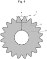
- Figure 4 is a radial cross sectional view (the X-X' cross sectional view of Figure 2 ) of the gear component 1.
- the distance between the tooth section 14 and the inner pore 15 is the rim thickness D.
- Figure 5 is an enlarged view of a part B shown in Figure 4 .
- the tooth section 14 comprises the mother phase 11, the carburized layer 12, and the carbide layer 13 formed in that order from the core part toward the surface 10 of the gear component 1.
- An area including a tip section of the tooth section 14 is the tooth tip 16, and an area including the point of intersection between the surface 10 and the pitch circle R is the tooth surface 17.
- An area including a point of contact between a line that makes a 30-degree angle with the center line P of the tooth section 14 and the surface 10 is the tooth root (tooth bottom) 18.
- the tooth section 14 comprises the tooth root 18, the tooth tip 16, and the tooth surface 17 between the tooth root 18 and the tooth tip 16.
- the area percentage of carbides in at least a part thereof is 10% or lower, and the number density of carbides is 6 pieces/10 ⁇ m 2 or lower.
- the area percentage of carbides exceeding 10% results in the lowered concentration of an alloying element, such as chromium, in the mother phase, the lowered hardenability, and the lowered hardness. As a consequence, the bending fatigue strength of the tooth root 18 is deteriorated.
- the number density of carbides exceeding 6 pieces/10 ⁇ m 2 results in the increased surface area at the interface between the carbides and the mother phase, the structure with hardness lower than that of the martensite is likely to be formed during hardening, and the bending fatigue strength of the tooth root 18 is then deteriorated.
- the area percentage of carbides in at least a part thereof is preferably 10% or lower.
- the area percentage of carbides exceeds 10% in the carbide layer 13 on the tooth surface 17, coarse carbides are likely to cause and spread cracks while the gear is operated. This may shorten the pitting fatigue life of the tooth surface.
- the area percentage of carbides in the carbide layer 13 on the tooth surface 17 is preferably larger than the area percentage of carbides in the carbide layer 13 of the tooth root 18. As the area percentage of carbides in the carbide layer 13 on the tooth surface 17 becomes smaller, the effects of the carbides on the tooth surface 17 for improving the pitting fatigue life becomes smaller. When the area percentage of carbides becomes larger in the carbide layer 13 of the tooth root 18, in contrast, the concentration of an alloying element, such as chromium, in the mother phase of the tooth root 18 is lowered, the hardenability is lowered, and hardness is lowered. This deteriorates the bending fatigue strength of the tooth root 18.
- Thickness of the carbide layer 13 of the tooth root 18 is preferably larger than thickness of the carbide layer 13 on the tooth surface 17. Thickness of the carbide layer 13 on the tooth surface 17 or the tooth root 18 is thickness of the carbide layer 13 measured in the direction perpendicular to the surface of the tooth surface 17 or the tooth root 18. On the tooth surface 17, the interior-inclusion-induced pitting fatigue damage is generated at the depth where the shear stress becomes maximal. Accordingly, the carbide layer 13 may be located at a level lower than the depth where the shear stress becomes maximal, and the carbide layer 13 may not be thick. As the thickness of the carbide layer 13 of the tooth root 18 is increased, in contrast, the residual stress of the tooth root 18 is increased, and the bending fatigue strength of the tooth root is improved. When thickness of the carbide layer 13 of the tooth root 18 is larger than thickness of the carbide layer 13 on the tooth surface 17, accordingly, the durability of the entire gear is improved.
- Figure 6 shows a step of producing the gear component according to an embodiment of the present invention.
- the steel material having the element composition described above is adequately subjected to hot forging and then to normalizing, so as to eliminate the influence of the processed structure and the distortion due to processing.
- the resultant is then subjected to gear cutting in the form of a gear and then to surface hardening by super-carburizing and tempering.
- finish processing may be performed after the tempering, so as to reduce the distortion due to heat treatment.
- Figure 7 shows the outline of the step of the super-carburizing treatment.
- the step of the super-carburizing treatment performed when producing the gear component according to an embodiment of the present invention is described with reference to Figure 7 .
- the step of the super-carburizing treatment comprises a step of carburizing and a step of reheating.
- the gear component 1 is soaked, and hydrocarbon gas, such as acetylene, is introduced intermittently for a given period of time.
- hydrocarbon gas such as acetylene
- carbon is introduced into the material from the surface thereof and diffused therein to form the carburized layer 12 and the carbide layer 13.
- the step of carburizing is performed at a temperature equivalent to or higher than the A1 transformation temperature.
- the step of carburizing is performed at a temperature lower than the A1 transformation temperature, the structure would not be transformed into austenite, and it would not be carburized.
- the duration of carburizing is shortened, although the distortion due to heat treatment becomes larger.
- the step of carburizing be performed at approximately 980°C to 1050°C.
- a temperature may adequately be changed, according to need.
- a duration of the step of carburizing is preferably approximately 1 to 10 hours, so as to achieve thickness of the carburized layer 12 that is necessary for the gear component.
- the surface carbon concentration is preferably equal to or higher than the eutectoid carbon concentration, and carburizing is preferably performed, so as to satisfy the condition such that the carbon concentration would be lower than the carbon concentration corresponding to the Acm line at the temperature in the step of carburizing.
- carbides are diffused in the carbide layer 13 after the step of reheating. With the aid of such carbides, the bending fatigue strength and the pitting fatigue life are improved.
- the surface carbon concentration is equivalent to or higher than the carbon concentration corresponding to the Acm line at the temperature in the step of carburizing, coarse carbides are precipitated along the prior austenite grain boundaries during the step of carburizing. Since the coarse carbides precipitated along the grain boundaries remain after the step of reheating, the hardenability is deteriorated, and hardness of the tooth root is lowered.
- a cooling rate is not particularly limited, provided that the carbon concentration is maintained in the oversaturated state during cooling and coarse carbides would not be formed in the subsequent step of reheating.
- a temperature after cooling in the step of carburizing should be lower than the A1 point. When a temperature after cooling in the step of carburizing is equivalent to or higher than the A1 point, austenite would not be transformed into pearlite, and carbides would not be diffused in the carbide layer 13 in the step of reheating.
- the gear component 1 is soaked, and hydrocarbon gas, such as acetylene, is introduced intermittently for a given period of time.
- hydrocarbon gas such as acetylene
- carbon is introduced into the material from the surface thereof and diffused therein for hardening.
- carbides mainly, the nuclei of carbides in the carbide layer 13 formed during cooling in the step of carburizing and during heating and soaking in the step of reheating, are regulated to have the area percentage and the number density that are necessary to improve hardness of the tooth root. Following the hardening, accordingly, the gear component 1 with high hardness of the tooth root can be obtained.
- the carbides in the carbide layer 13 obtained at the oversaturated carbon concentration after the step of carburizing can satisfy the conditions of the area percentage and the number density of the carbides, acetylene or the like may not be introduced in the step of reheating.
- the step of reheating is preferably performed at a temperature equivalent to or higher than the A1 transformation temperature, and more preferably at a temperature lower than the Acm temperature at the surface carbon concentration upon completion of the step of reheating.
- the step of reheating is performed at a temperature lower than the A1 transformation temperature, the structure would not be transformed into austenite, and the gear component 1 would not be hardened during the process of hardening.
- the step of reheating When the step of reheating is performed at a temperature equivalent to or higher than the Acm temperature at the surface carbon concentration of the component upon completion of the step of reheating, carbides precipitated in the carbide layer 13 would form a solid solution. As the temperature in the step of reheating is increased, the number density of carbides in the carbide layer 13 is decreased. Since the amount of the austenite remaining after hardening is increased and the hardness is lowered, the temperature is preferably approximately 820°C to 900°C.
- a duration of the step of reheating is preferably longer than a duration of reheating that is generally employed, such as approximately for 3 to 24 hours, so as to allow the carbides in the carbide layer 13 to undergo Ostwald ripening and satisfy the conditions of the area percentage and the number density of carbides.
- a temperature may be adequately changed during processing, and a process of cooling and heating may be adequately added.
- the temperature after hardening in the step of reheating should be lower than the Ms point. If the temperature after hardening in the step of reheating is equivalent to or higher than the Ms point, austenite would not be transformed into martensite, and the material would not be hardened.
- a temperature is adequately set within the range from 150°C to 250°C to soak the gear component 1.
- a duration of treatment is not particularly limited, and a method of cooling is not particularly limited, provided that the gear component 1 is soaked.
- the gear components 1 of Examples 1 to 3 and Comparative Examples 1 to 5 were prepared by changing the super-carburizing treatment conditions and the rim thickness D.
- Figure 8 shows the outline of the step of super-carburizing treatment in the examples and the comparative examples.
- the area percentage of carbides and the number density of carbides of the tooth surface 17 and the tooth root 18 were determined with the use of image analysis software by subjecting the radial cross section of the gear component as shown in Figure 4 to etching in sodium picrate heated to 80°C for 20 minutes and selectively allowing carbides to appear in black.
- the hardness ratio of the tooth tip 16, the tooth surface 17, and the tooth root 18 was determined by dividing the value obtained by testing the radial cross section of the gear component shown in Figure 4 using the Vickers hardness tester by the value obtained by testing the eutectoid-carburized gear component.
- the fatigue life of the tooth surface was evaluated by an element test simulating the tooth surface fatigue; i.e., the tooth surface fatigue test.
- Figure 9 shows the configurations of test pieces used in the tooth surface fatigue tests performed in the examples and the comparative examples.
- the small gear 20 was prepared by subjecting the steel material of the element composition described above to hot forging, normalizing, gear cutting, super-carburizing shown in Table 1, and tempering.
- the large gear 30 was prepared by subjecting the steel material of the element composition described above to hot forging, normalizing, gear cutting, eutectoid carburizing, and tempering.
- the tooth surface fatigue test was performed by meshing the small gear 20 with the large gear 30 and testing the meshed gears with the use of a gear reducer lubricant oil at 70°C with the hertz contact pressure of 230 kgf/mm 2 .
- the tooth surface fatigue life was evaluated based on the number of cycles of the small gear 20 before the pitting fatigue damage appeared on the tooth surface of the small gear 20.
- the ratio of the tooth surface fatigue life was determined by dividing the value indicating the tooth surface fatigue life of the super-carburized small gear 20 by the value indicating the tooth surface fatigue life of the eutectoid-carburized small gear 20.
- the symbol "*" indicates that the surface layer of the tooth root or the tooth surface includes a region where the area percentage of carbides is higher than 10% or a region where the number density of carbides of the tooth root is higher than 6 pieces/10 ⁇ m 2 .
- the gear component 1 with the rim thickness D of 50 mm or 120 mm was treated under the super-carburizing treatment conditions shown in Figure 8A while regulating the duration of the step of reheating within a range of 3 to 24 hours.
- the surface layer of the tooth root was regulated to include a region in which the area percentage of carbides would be 10% or lower and the number density of carbides would be 6 pieces/10 ⁇ m 2 or lower, and the surface layer on the tooth surface was regulated to include a region in which the area percentage of carbides would be 10% or lower.
- the gear component 1 with the rim thickness D of 50 mm or 120 mm was treated under the super-carburizing treatment conditions shown in Figure 8B while regulating the duration of the step of reheating within a range of 1 to 3 hours.
- the surface layer of the tooth root was regulated to include a region in which the area percentage of carbides would be higher than 10% or the number density of carbides would be higher than 6 pieces/10 ⁇ m 2 .
- the surface layer on the tooth surface was regulated to include a region in which the area percentage of carbides would be higher than 10%.
- the gear component 1 with the rim thickness of 50 mm was treated under the super-carburizing treatment conditions shown in Figure 8C while regulating the duration of the step of reheating within a range of 3 to 12 hours and introducing hydrocarbon gas intermittently for a given period of time in the step of reheating.
- the surface layer of the tooth root and that of the tooth surface were each regulated to include a region in which the area percentage of carbides would be higher than 10%.
- Figure 10 shows charts demonstrating the correlation between the structure and the properties of materials tested in the examples and the comparative examples.
- Figure 10A shows the correlation between the number density of carbides in the tooth root and the hardness ratio of the tooth root, and the correlation of the gear components of the examples and the comparative examples shown in Table 1 exhibiting the area percentage of carbides in the tooth root of 10% or lower is plotted.
- the hardness ratio of the tooth root begins to significantly change at the number density of carbides of 6 pieces/10 ⁇ m 2 in the tooth root.
- Figure 10B shows the correlation between the area percentage of carbides in the tooth root and the hardness ratio of the tooth root, and the correlation of the gear components of the examples and the comparative examples shown in Table 1 exhibiting the number density of carbides in the tooth root of 6 pieces/10 ⁇ m 2 or lower is plotted.
- the hardness ratio of the tooth root begins to significantly change at the area percentage of carbides of 10% in the tooth root.
- Figure 10C shows the correlation between the area percentage of carbides in the tooth surface and the ratio of the fatigue life of the tooth surface. The ratio of the fatigue life of the tooth surface begins to significantly change at the area percentage of carbides of 10% on the tooth surface.
- the present invention is not limited to the examples described above, and the present invention can be implemented with various modifications performed within the scope of the present invention.
- the area percentage of carbides may be 10% or lower and the number density of carbides may be 6 pieces/10 ⁇ m 2 or lower.
Landscapes
- Chemical & Material Sciences (AREA)
- Engineering & Computer Science (AREA)
- Mechanical Engineering (AREA)
- Thermal Sciences (AREA)
- Physics & Mathematics (AREA)
- Materials Engineering (AREA)
- Metallurgy (AREA)
- Organic Chemistry (AREA)
- Crystallography & Structural Chemistry (AREA)
- General Engineering & Computer Science (AREA)
- Electromagnetism (AREA)
- Chemical Kinetics & Catalysis (AREA)
- Solid-Phase Diffusion Into Metallic Material Surfaces (AREA)
- Heat Treatment Of Articles (AREA)
- Gears, Cams (AREA)
Abstract
Description
- The present invention relates to a super-carburized gear component.
- A gear, which is a component of a power transmission device as typified by a transmission, a reducer, or the like, is generally produced by molding a case hardening steel in the form of a component and subjecting the component to carburizing or carbonitriding. In recent years, downsizing and compactification of a gear aimed at cost reduction has been in progress, and, accordingly, development of a component with a higher strength has been awaited.
- In order to achieve compactification, the load imposed on each gear increases. Because of the increased load, a demand for the improved durability is increasing. Techniques for improving the durability that have been known are the carburizing treatment for strengthening a component by introducing carbon into heated steel and hardening the steel at atmospheric pressure and forming a hard martensitic structure and the vacuum carburizing treatment for preventing formation of the brittle grain-boundary oxide, which becomes the starting point of fatigue fracture, by performing the carburizing treatment at reduced pressure are known. In recent years, the super-carburizing treatment for strengthening a component by introducing carbon at the eutectoid concentration or higher into steel and depositing a hard carbide in the martensitic mother phase has been adopted.
- In the super-carburizing treatment, in general, the form of carbide deposition is known to influence the durability. For example,
Patent Literature 1 discloses a steel component for a machine structure with the area percentage of carbides of 5% or more and the surface density of carbides with diameters of 0.5 µm or less of 6.0 pieces/10 µm2 or more. With the use of such component, fine carbides are diffused and deposited, and the pitting resistance of the carbides can be improved. - Patent Literature 1:
JP Patent Publication (Kokai) No. 2005-113168 A - In the component disclosed in
Patent Literature 1, however, the surface area at the interface between a large quantity of deposited carbides and the mother phase increases. This interface is thermodynamically unstable, and it is likely to serve as the core of pearlite transformation, bainite transformation, or the like during hardening. In addition, an alloying element, such as chromium, in the mother phase is concentrated in carbides, the concentration of the alloying element, such as chromium, is decreased in the mother phase in the vicinity of the interface, and the hardenability is then lowered. Thus, a structure, such as a pearlite or bainite structure, with hardness lower than that of the martensite is likely to be formed during hardening. Such phenomenon is likely to occur when it is applied to a gear with a large rim thickness and a large heat capacity, and such phenomenon is observed at a significant level at the tooth root where a cooling rate is particularly low. This lowers hardness of the tooth root surface layer and lowers the bending fatigue strength of the tooth root, disadvantageously. When the improved strength and the prolonged life of the entire gear are intended, in other words, attention may be paid to the tooth root in order to achieve the improved strength and the prolonged life of the gear. - In order to overcome the problems of the conventional technique, it is an object of the present invention to provide a gear component with a hard surface layer of the tooth root and the excellent bending fatigue strength.
- In order to achieve the object described above, the gear component of the present invention comprises a tooth section having a tooth root, a tooth tip, and a tooth surface between the tooth root and the tooth tip and consists of a super-carburized steel material, wherein the tooth root has a carbide layer comprising carbides diffused and deposited on a surface layer, and the area percentage of carbides is 10% or lower and the number density of carbides is 6 pieces/10 µm2 or lower in at least a part of the carbide layer of the tooth root.
- The description incorporates the contents disclosed by
JP Patent Application No. 2022-050297 - With the use of the gear component of the present invention, the area percentage of carbides is reduced, and a surface area at the interface between the carbides and the mother phase is reduced. Thus, the core for pearlite transformation, bainite transformation, or the like during hardening is reduced, an extent of a decrease in the concentration of an alloying element, such as chromium, in the mother phase is reduced in the vicinity of the interface, and an extent of lowering in hardenability is reduced. As a result, a soft structure of pearlite, bainite, or the like is less likely to be formed during hardening, hardness of the surface layer of the tooth root is improved, and the bending fatigue strength of the tooth root is improved.
-
- [
Figure 1] Figure 1 is a perspective view demonstrating an embodiment of the gear component according to the present invention. - [
Figure 2] Figure 2 is an axial cross sectional view of the gear component according to an embodiment of the present invention. - [
Figure 3] Figure 3 is an enlarged view of a part A shown inFigure 2 . - [
Figure 4] Figure 4 is a radial cross sectional view of the gear component according to an embodiment of the present invention. - [
Figure 5] Figure 5 is an enlarged view of a part B shown inFigure 4 . - [
Figure 6] Figure 6 shows a step of producing the gear component according to an embodiment of the present invention. - [
Figure 7] Figure 7 shows the outline of the step of the super-carburizing treatment. - [
Figure 8] Figure 8 shows the outline of the step of the super-carburizing treatment performed in the examples and the comparative examples. - [
Figure 9] Figure 9 shows the configurations of test pieces used in the tooth surface fatigue tests performed in the examples and the comparative examples. - [
Figure 10] Figure 10 shows charts demonstrating the correlation between the structure and the properties of materials tested in the examples and the comparative examples. - Hereafter, an embodiment of the gear component according to the present invention is described with reference to the figures.
- At the outset, the element composition of the gear component of the present invention is described. The gear component comprises various alloying elements with the balance consisting of a steel material comprising Fe and unavoidable impurities. Specifically, the gear component can be composed of a material, such as Cr steel (SCr material), Cr-Mo steel (SCM material), or Ni-Cr-Mo steel (SNCM material), as defined in, for example, JIS G4053.
-
Figure 1 is a perspective view demonstrating the gear component according to an embodiment of the present invention. Thegear component 1 can be used as a gear for a construction machine, such as a hydraulic shovel or dump truck, although the application thereof is not limited thereto. -
Figure 2 is an axial cross sectional view of thegear component 1, andFigure 3 is an enlarged view of a part A shown inFigure 2 that schematically shows an axial cross section of thegear component 1. As a result of the super-carburizing treatment, thegear component 1 has an internal structure comprising amother phase 11, acarburized layer 12, and acarbide layer 13 formed in that order from the core part toward thesurface 10. In thecarburized layer 12, carbon concentration is higher than that in themother phase 11. In thecarburized layer 12, carbon concentration is particularly high in thecarbide layer 13, which is a layered region where carbides are diffused and deposited. The super-carburizing treatment can be referred to as a carburizing treatment that forms thecarbide layer 13 as described above (i.e., the super-carburizing treatment is performed, so as to allow carbides to precipitate in a region near the surface). Thecarburized layer 12 and thecarbide layer 13 can be collectively referred to as a layer with higher carbon concentration than that in the mother phase 11 (i.e., the carburizing treatment layer). -
Figure 4 is a radial cross sectional view (the X-X' cross sectional view ofFigure 2 ) of thegear component 1. The distance between thetooth section 14 and theinner pore 15 is the rim thickness D. -
Figure 5 is an enlarged view of a part B shown inFigure 4 . As shown in the enlarged view of the axial cross section of thegear component 1 inFigure 3 , thetooth section 14 comprises themother phase 11, thecarburized layer 12, and thecarbide layer 13 formed in that order from the core part toward thesurface 10 of thegear component 1. An area including a tip section of thetooth section 14 is thetooth tip 16, and an area including the point of intersection between thesurface 10 and the pitch circle R is thetooth surface 17. An area including a point of contact between a line that makes a 30-degree angle with the center line P of thetooth section 14 and thesurface 10 is the tooth root (tooth bottom) 18. Specifically, thetooth section 14 comprises thetooth root 18, thetooth tip 16, and thetooth surface 17 between thetooth root 18 and thetooth tip 16. - In the surface layer of the
tooth root 18; i.e., thecarbide layer 13 of thetooth root 18, the area percentage of carbides in at least a part thereof is 10% or lower, and the number density of carbides is 6 pieces/10 µm2 or lower. Concerning thecarbide layer 13 of thetooth root 18, the area percentage of carbides exceeding 10% results in the lowered concentration of an alloying element, such as chromium, in the mother phase, the lowered hardenability, and the lowered hardness. As a consequence, the bending fatigue strength of thetooth root 18 is deteriorated. The number density of carbides exceeding 6 pieces/10 µm2 results in the increased surface area at the interface between the carbides and the mother phase, the structure with hardness lower than that of the martensite is likely to be formed during hardening, and the bending fatigue strength of thetooth root 18 is then deteriorated. - In the surface layer on the
tooth surface 17; i.e., thecarbide layer 13 on thetooth surface 17, the area percentage of carbides in at least a part thereof is preferably 10% or lower. When the area percentage of carbides exceeds 10% in thecarbide layer 13 on thetooth surface 17, coarse carbides are likely to cause and spread cracks while the gear is operated. This may shorten the pitting fatigue life of the tooth surface. - The area percentage of carbides in the
carbide layer 13 on thetooth surface 17 is preferably larger than the area percentage of carbides in thecarbide layer 13 of thetooth root 18. As the area percentage of carbides in thecarbide layer 13 on thetooth surface 17 becomes smaller, the effects of the carbides on thetooth surface 17 for improving the pitting fatigue life becomes smaller. When the area percentage of carbides becomes larger in thecarbide layer 13 of thetooth root 18, in contrast, the concentration of an alloying element, such as chromium, in the mother phase of thetooth root 18 is lowered, the hardenability is lowered, and hardness is lowered. This deteriorates the bending fatigue strength of thetooth root 18. When the area percentage of carbides of the surface layer on thetooth surface 17 becomes smaller or when the area percentage of carbides in the surface layer of thetooth root 18 becomes larger and the area percentage of carbides of the surface layer on thetooth surface 17 becomes equivalent to or lower than the area percentage of carbides in the surface layer of thetooth root 18, accordingly, the durability of the entire gear may be deteriorated. - Thickness of the
carbide layer 13 of thetooth root 18 is preferably larger than thickness of thecarbide layer 13 on thetooth surface 17. Thickness of thecarbide layer 13 on thetooth surface 17 or thetooth root 18 is thickness of thecarbide layer 13 measured in the direction perpendicular to the surface of thetooth surface 17 or thetooth root 18. On thetooth surface 17, the interior-inclusion-induced pitting fatigue damage is generated at the depth where the shear stress becomes maximal. Accordingly, thecarbide layer 13 may be located at a level lower than the depth where the shear stress becomes maximal, and thecarbide layer 13 may not be thick. As the thickness of thecarbide layer 13 of thetooth root 18 is increased, in contrast, the residual stress of thetooth root 18 is increased, and the bending fatigue strength of the tooth root is improved. When thickness of thecarbide layer 13 of thetooth root 18 is larger than thickness of thecarbide layer 13 on thetooth surface 17, accordingly, the durability of the entire gear is improved. - Subsequently, a method for producing the gear component according to an embodiment of the present invention is described with reference to the figures.
-
Figure 6 shows a step of producing the gear component according to an embodiment of the present invention. In order to prepare a gear component with an adequate dimension, at the outset, the steel material having the element composition described above is adequately subjected to hot forging and then to normalizing, so as to eliminate the influence of the processed structure and the distortion due to processing. The resultant is then subjected to gear cutting in the form of a gear and then to surface hardening by super-carburizing and tempering. According to need, finish processing may be performed after the tempering, so as to reduce the distortion due to heat treatment. -
Figure 7 shows the outline of the step of the super-carburizing treatment. Hereafter, the step of the super-carburizing treatment performed when producing the gear component according to an embodiment of the present invention is described with reference toFigure 7 . As shown inFigure 7 , the step of the super-carburizing treatment comprises a step of carburizing and a step of reheating. - In the step of carburizing, the
gear component 1 is soaked, and hydrocarbon gas, such as acetylene, is introduced intermittently for a given period of time. Thus, carbon is introduced into the material from the surface thereof and diffused therein to form the carburizedlayer 12 and thecarbide layer 13. The step of carburizing is performed at a temperature equivalent to or higher than the A1 transformation temperature. When the step of carburizing is performed at a temperature lower than the A1 transformation temperature, the structure would not be transformed into austenite, and it would not be carburized. As the step of carburizing is performed at a higher temperature, the duration of carburizing is shortened, although the distortion due to heat treatment becomes larger. It is accordingly preferable that the step of carburizing be performed at approximately 980°C to 1050°C. During the step of carburizing, a temperature may adequately be changed, according to need. A duration of the step of carburizing is preferably approximately 1 to 10 hours, so as to achieve thickness of the carburizedlayer 12 that is necessary for the gear component. When the step of carburizing is completed, the surface carbon concentration is preferably equal to or higher than the eutectoid carbon concentration, and carburizing is preferably performed, so as to satisfy the condition such that the carbon concentration would be lower than the carbon concentration corresponding to the Acm line at the temperature in the step of carburizing. By adjusting the surface carbon concentration to a level equivalent to or higher than the eutectoid carbon concentration, carbides are diffused in thecarbide layer 13 after the step of reheating. With the aid of such carbides, the bending fatigue strength and the pitting fatigue life are improved. When the surface carbon concentration is equivalent to or higher than the carbon concentration corresponding to the Acm line at the temperature in the step of carburizing, coarse carbides are precipitated along the prior austenite grain boundaries during the step of carburizing. Since the coarse carbides precipitated along the grain boundaries remain after the step of reheating, the hardenability is deteriorated, and hardness of the tooth root is lowered. When the surface carbon concentration upon completion of the step of carburizing is higher, the area percentage of carbides after the step of reheating is increased, the hardenability is lowered, and hardness of the tooth root after the step of reheating is lowered. Thus, such surface carbon concentration is preferably between 1.0 wt% and 2.0 wt%. In the step of carburizing, a cooling rate is not particularly limited, provided that the carbon concentration is maintained in the oversaturated state during cooling and coarse carbides would not be formed in the subsequent step of reheating. A temperature after cooling in the step of carburizing should be lower than the A1 point. When a temperature after cooling in the step of carburizing is equivalent to or higher than the A1 point, austenite would not be transformed into pearlite, and carbides would not be diffused in thecarbide layer 13 in the step of reheating. - In the step of reheating, the
gear component 1 is soaked, and hydrocarbon gas, such as acetylene, is introduced intermittently for a given period of time. Thus, carbon is introduced into the material from the surface thereof and diffused therein for hardening. Thus, carbides, mainly, the nuclei of carbides in thecarbide layer 13 formed during cooling in the step of carburizing and during heating and soaking in the step of reheating, are regulated to have the area percentage and the number density that are necessary to improve hardness of the tooth root. Following the hardening, accordingly, thegear component 1 with high hardness of the tooth root can be obtained. If the carbides in thecarbide layer 13 obtained at the oversaturated carbon concentration after the step of carburizing can satisfy the conditions of the area percentage and the number density of the carbides, acetylene or the like may not be introduced in the step of reheating. The step of reheating is preferably performed at a temperature equivalent to or higher than the A1 transformation temperature, and more preferably at a temperature lower than the Acm temperature at the surface carbon concentration upon completion of the step of reheating. When the step of reheating is performed at a temperature lower than the A1 transformation temperature, the structure would not be transformed into austenite, and thegear component 1 would not be hardened during the process of hardening. When the step of reheating is performed at a temperature equivalent to or higher than the Acm temperature at the surface carbon concentration of the component upon completion of the step of reheating, carbides precipitated in thecarbide layer 13 would form a solid solution. As the temperature in the step of reheating is increased, the number density of carbides in thecarbide layer 13 is decreased. Since the amount of the austenite remaining after hardening is increased and the hardness is lowered, the temperature is preferably approximately 820°C to 900°C. A duration of the step of reheating is preferably longer than a duration of reheating that is generally employed, such as approximately for 3 to 24 hours, so as to allow the carbides in thecarbide layer 13 to undergo Ostwald ripening and satisfy the conditions of the area percentage and the number density of carbides. In order to regulate the structure, according to need, a temperature may be adequately changed during processing, and a process of cooling and heating may be adequately added. The temperature after hardening in the step of reheating should be lower than the Ms point. If the temperature after hardening in the step of reheating is equivalent to or higher than the Ms point, austenite would not be transformed into martensite, and the material would not be hardened. - In the step of tempering after the step of the super-carburizing treatment, a temperature is adequately set within the range from 150°C to 250°C to soak the
gear component 1. A duration of treatment is not particularly limited, and a method of cooling is not particularly limited, provided that thegear component 1 is soaked. - Hereafter, the present invention is described in greater detail with reference to the examples and the comparative examples.
- As shown in Table 1, the
gear components 1 of Examples 1 to 3 and Comparative Examples 1 to 5 were prepared by changing the super-carburizing treatment conditions and the rim thickness D.Figure 8 shows the outline of the step of super-carburizing treatment in the examples and the comparative examples. The area percentage of carbides and the number density of carbides of thetooth surface 17 and thetooth root 18 were determined with the use of image analysis software by subjecting the radial cross section of the gear component as shown inFigure 4 to etching in sodium picrate heated to 80°C for 20 minutes and selectively allowing carbides to appear in black. The hardness ratio of thetooth tip 16, thetooth surface 17, and thetooth root 18 was determined by dividing the value obtained by testing the radial cross section of the gear component shown inFigure 4 using the Vickers hardness tester by the value obtained by testing the eutectoid-carburized gear component. The fatigue life of the tooth surface was evaluated by an element test simulating the tooth surface fatigue; i.e., the tooth surface fatigue test.Figure 9 shows the configurations of test pieces used in the tooth surface fatigue tests performed in the examples and the comparative examples. Thesmall gear 20 was prepared by subjecting the steel material of the element composition described above to hot forging, normalizing, gear cutting, super-carburizing shown in Table 1, and tempering. Thelarge gear 30 was prepared by subjecting the steel material of the element composition described above to hot forging, normalizing, gear cutting, eutectoid carburizing, and tempering. The tooth surface fatigue test was performed by meshing thesmall gear 20 with thelarge gear 30 and testing the meshed gears with the use of a gear reducer lubricant oil at 70°C with the hertz contact pressure of 230 kgf/mm2. The tooth surface fatigue life was evaluated based on the number of cycles of thesmall gear 20 before the pitting fatigue damage appeared on the tooth surface of thesmall gear 20. The ratio of the tooth surface fatigue life was determined by dividing the value indicating the tooth surface fatigue life of the super-carburizedsmall gear 20 by the value indicating the tooth surface fatigue life of the eutectoid-carburizedsmall gear 20. In Table 1, the symbol "*" indicates that the surface layer of the tooth root or the tooth surface includes a region where the area percentage of carbides is higher than 10% or a region where the number density of carbides of the tooth root is higher than 6 pieces/10 µm2.[Table 1] Condition Rim thickness (mm) Number density of carbides in tooth root (pieces/ 10 µm2) Area ratio of carbides in tooth root (%) Area ratio of carbides on tooth surface (%) Hardness ratio of tooth tip Hardness ratio of tooth surface Hardness ratio of tooth root Ratio of fatigue life of tooth surface Ex.1 a 50 2.2 3.8 5.0 1.2 1.1 1.1 >5.0 Ex.2 a 50 4.5 9.9 7.6 1.1 1.1 1.1 3.5 Ex.3 a 120 5.0 8.3 8.0 1.2 1.2 1.2 >5.0 Comp. Ex.1 b 50 *10.4 9.1 8.1 1.2 1.2 0.8 3.3 Comp. Ex.2 b 50 *7.0 9.5 9.3 1.2 1.1 0.9 3.3 Comp. Ex.3 c 50 1.8 *14.6 *12.2 1.1 1.1 0.6 1.5 Comp. Ex.4 b 120 5.2 *10.5 *10.5 1.2 1.2 0.9 1.5 Comp. Ex.5 b 120 *6.1 8.1 9.0 1.2 1.4 0.8 4.3 - In Examples 1 to 3, the
gear component 1 with the rim thickness D of 50 mm or 120 mm was treated under the super-carburizing treatment conditions shown inFigure 8A while regulating the duration of the step of reheating within a range of 3 to 24 hours. Thus, the surface layer of the tooth root was regulated to include a region in which the area percentage of carbides would be 10% or lower and the number density of carbides would be 6 pieces/10 µm2 or lower, and the surface layer on the tooth surface was regulated to include a region in which the area percentage of carbides would be 10% or lower. - In Comparative Examples 1, 2, 4, and 5, the
gear component 1 with the rim thickness D of 50 mm or 120 mm was treated under the super-carburizing treatment conditions shown inFigure 8B while regulating the duration of the step of reheating within a range of 1 to 3 hours. Thus, the surface layer of the tooth root was regulated to include a region in which the area percentage of carbides would be higher than 10% or the number density of carbides would be higher than 6 pieces/10 µm2. In Comparative Example 4, in addition, the surface layer on the tooth surface was regulated to include a region in which the area percentage of carbides would be higher than 10%. - In Comparative Example 3, the
gear component 1 with the rim thickness of 50 mm was treated under the super-carburizing treatment conditions shown inFigure 8C while regulating the duration of the step of reheating within a range of 3 to 12 hours and introducing hydrocarbon gas intermittently for a given period of time in the step of reheating. Thus, the surface layer of the tooth root and that of the tooth surface were each regulated to include a region in which the area percentage of carbides would be higher than 10%. -
Figure 10 shows charts demonstrating the correlation between the structure and the properties of materials tested in the examples and the comparative examples.Figure 10A shows the correlation between the number density of carbides in the tooth root and the hardness ratio of the tooth root, and the correlation of the gear components of the examples and the comparative examples shown in Table 1 exhibiting the area percentage of carbides in the tooth root of 10% or lower is plotted. The hardness ratio of the tooth root begins to significantly change at the number density of carbides of 6 pieces/10 µm2 in the tooth root.Figure 10B shows the correlation between the area percentage of carbides in the tooth root and the hardness ratio of the tooth root, and the correlation of the gear components of the examples and the comparative examples shown in Table 1 exhibiting the number density of carbides in the tooth root of 6 pieces/10 µm2 or lower is plotted. The hardness ratio of the tooth root begins to significantly change at the area percentage of carbides of 10% in the tooth root.Figure 10C shows the correlation between the area percentage of carbides in the tooth surface and the ratio of the fatigue life of the tooth surface. The ratio of the fatigue life of the tooth surface begins to significantly change at the area percentage of carbides of 10% on the tooth surface. - The present invention is not limited to the examples described above, and the present invention can be implemented with various modifications performed within the scope of the present invention. In at least a part of the
carbide layer 13 of thetooth root 18, for example, the area percentage of carbides may be 10% or lower and the number density of carbides may be 6 pieces/10 µm2 or lower. -
- 1: Gear component
- 10: Surface
- 11: Mother phase
- 12: Carburized layer
- 13: Carbide layer
- 14: Tooth section
- 15: Inner pore
- 16: Tooth tip
- 17: Tooth surface
- 18: Tooth root
- 20: Small gear
- 30: Large gear
- D: Rim thickness
- R: Pitch circle
- W: Tooth width
- P: Center line
- All publications, patents, and patent applications cited herein are incorporated herein by reference in their entirety.
Claims (4)
- A gear component comprising a tooth section having a tooth root, a tooth tip, and a tooth surface between the tooth root and the tooth tip and consisting of a super-carburized steel material,wherein the tooth root has a carbide layer comprising carbides diffused and deposited on a surface layer, andthe area percentage of carbides is 10% or lower and the number density of carbides is 6 pieces/10 µm2 or lower in at least a part of the carbide layer of the tooth root.
- The gear component according to claim 1, wherein the tooth surface has a carbide layer comprising carbides diffused and deposited on a surface layer, and the area percentage of carbides is 10% or lower in at least a part of the carbide layer of the tooth surface.
- The gear component according to claim 1, wherein the tooth surface has a carbide layer comprising carbides diffused and deposited on a surface layer, and the area percentage of carbides in the carbide layer on the tooth surface is larger than the area percentage of carbides in the carbide layer of the tooth root.
- The gear component according to claim 1, wherein the tooth surface has a carbide layer comprising carbides diffused and deposited on a surface layer, and thickness of the carbide layer of the tooth root is larger than thickness of the carbide layer of the tooth surface.
Applications Claiming Priority (2)
| Application Number | Priority Date | Filing Date | Title |
|---|---|---|---|
| JP2022050297 | 2022-03-25 | ||
| PCT/JP2023/011142 WO2023182333A1 (en) | 2022-03-25 | 2023-03-22 | Gear component |
Publications (2)
| Publication Number | Publication Date |
|---|---|
| EP4502226A1 true EP4502226A1 (en) | 2025-02-05 |
| EP4502226A4 EP4502226A4 (en) | 2026-01-14 |
Family
ID=88101127
Family Applications (1)
| Application Number | Title | Priority Date | Filing Date |
|---|---|---|---|
| EP23774928.8A Pending EP4502226A4 (en) | 2022-03-25 | 2023-03-22 | GEARBOX COMPONENT |
Country Status (5)
| Country | Link |
|---|---|
| US (1) | US12338885B2 (en) |
| EP (1) | EP4502226A4 (en) |
| JP (1) | JP7745747B2 (en) |
| CN (1) | CN118382717A (en) |
| WO (1) | WO2023182333A1 (en) |
Family Cites Families (11)
| Publication number | Priority date | Publication date | Assignee | Title |
|---|---|---|---|---|
| JP3271659B2 (en) * | 1998-06-29 | 2002-04-02 | 日産自動車株式会社 | High strength gear and manufacturing method thereof |
| JP4022607B2 (en) * | 1999-07-21 | 2007-12-19 | 日産自動車株式会社 | Manufacturing method of high surface pressure resistant member |
| JP3781172B2 (en) | 2000-10-06 | 2006-05-31 | 日産自動車株式会社 | Gear manufacturing method |
| JP4356923B2 (en) | 2003-10-03 | 2009-11-04 | 株式会社神戸製鋼所 | Steel parts for machine structures |
| JP2005163173A (en) | 2003-11-14 | 2005-06-23 | Komatsu Ltd | Gear member and manufacturing method thereof |
| US8733199B2 (en) * | 2010-04-01 | 2014-05-27 | Aisin Aw Co., Ltd. | Gears and its process of manufacture |
| JP2016023346A (en) | 2014-07-23 | 2016-02-08 | トヨタ自動車株式会社 | Carburization method of gear |
| US10494687B2 (en) * | 2015-02-04 | 2019-12-03 | Sikorsky Aircraft Corporation | Methods and processes of forming gears |
| EP3378963B1 (en) * | 2016-03-08 | 2022-07-13 | Aisin Corporation | Steel component, gear component, and method for manufacturing steel component |
| KR102820108B1 (en) * | 2020-01-20 | 2025-06-16 | 현대자동차주식회사 | Carburized steel for vehicle parts and method for manufacturing the cabrurizded steel |
| JP7006820B1 (en) | 2020-09-17 | 2022-02-15 | 株式会社明電舎 | Filter unit and wastewater treatment equipment |
-
2023
- 2023-03-22 US US18/729,905 patent/US12338885B2/en active Active
- 2023-03-22 JP JP2024510212A patent/JP7745747B2/en active Active
- 2023-03-22 CN CN202380015096.6A patent/CN118382717A/en active Pending
- 2023-03-22 WO PCT/JP2023/011142 patent/WO2023182333A1/en not_active Ceased
- 2023-03-22 EP EP23774928.8A patent/EP4502226A4/en active Pending
Also Published As
| Publication number | Publication date |
|---|---|
| JPWO2023182333A1 (en) | 2023-09-28 |
| WO2023182333A1 (en) | 2023-09-28 |
| US20250102054A1 (en) | 2025-03-27 |
| JP7745747B2 (en) | 2025-09-29 |
| EP4502226A4 (en) | 2026-01-14 |
| US12338885B2 (en) | 2025-06-24 |
| CN118382717A (en) | 2024-07-23 |
Similar Documents
| Publication | Publication Date | Title |
|---|---|---|
| EP3378963B1 (en) | Steel component, gear component, and method for manufacturing steel component | |
| JP4927234B2 (en) | Surface hardened steel part and method for manufacturing the same | |
| JP3308377B2 (en) | Gear with excellent tooth surface strength and method of manufacturing the same | |
| EP2546381A1 (en) | Carburized steel member and method for producing same | |
| EP2085493A1 (en) | Process for producing high-concentration carburized steel | |
| KR101474627B1 (en) | Steel for high frequency hardening, roughly molded material for high frequency hardening and process for production thereof, and high-frequency-hardened steel member | |
| EP2548986A1 (en) | Steel for nitrocarburization, nitrocarburized components, and production method for same | |
| KR101127909B1 (en) | Gear part and method of producing thereof | |
| JP3562192B2 (en) | Component for induction hardening and method of manufacturing the same | |
| JP4688727B2 (en) | Carburized parts and manufacturing method thereof | |
| EP1548141B1 (en) | Machine part and method for manufacturing same | |
| WO2019244504A1 (en) | Method for producing machine components | |
| JPH11131176A (en) | Induction hardened part and method of manufacturing the same | |
| JP3543557B2 (en) | Carburized gear | |
| US12338885B2 (en) | Gear component | |
| JP2021167444A (en) | Compression coil spring | |
| JPH10147814A (en) | Manufacturing method of case hardened steel products with less heat treatment distortion | |
| JP3623313B2 (en) | Carburized gear parts | |
| KR20150074645A (en) | Material for high carburizing steel and method for producing gear using the same | |
| JPH05239602A (en) | High bearing pressure parts | |
| JPH05140726A (en) | Manufacturing method of drivetrain mechanical parts with high fatigue strength | |
| JP4526616B2 (en) | Gear made of spheroidal graphite cast iron material and manufacturing method thereof | |
| JP2021006659A (en) | Steel parts and their manufacturing methods | |
| JP4515329B2 (en) | Steel gear with excellent case crushing resistance and low heat distortion and its manufacturing method | |
| JP3104449B2 (en) | Heat treatment of carburized gears |
Legal Events
| Date | Code | Title | Description |
|---|---|---|---|
| STAA | Information on the status of an ep patent application or granted ep patent |
Free format text: STATUS: THE INTERNATIONAL PUBLICATION HAS BEEN MADE |
|
| PUAI | Public reference made under article 153(3) epc to a published international application that has entered the european phase |
Free format text: ORIGINAL CODE: 0009012 |
|
| STAA | Information on the status of an ep patent application or granted ep patent |
Free format text: STATUS: REQUEST FOR EXAMINATION WAS MADE |
|
| 17P | Request for examination filed |
Effective date: 20241025 |
|
| AK | Designated contracting states |
Kind code of ref document: A1 Designated state(s): AL AT BE BG CH CY CZ DE DK EE ES FI FR GB GR HR HU IE IS IT LI LT LU LV MC ME MK MT NL NO PL PT RO RS SE SI SK SM TR |
|
| DAV | Request for validation of the european patent (deleted) | ||
| DAX | Request for extension of the european patent (deleted) | ||
| REG | Reference to a national code |
Ref country code: DE Ref legal event code: R079 Free format text: PREVIOUS MAIN CLASS: C23C0008220000 Ipc: F16H0055060000 |
|
| A4 | Supplementary search report drawn up and despatched |
Effective date: 20251212 |
|
| RIC1 | Information provided on ipc code assigned before grant |
Ipc: F16H 55/06 20060101AFI20251208BHEP Ipc: C23C 8/22 20060101ALI20251208BHEP Ipc: C21D 1/06 20060101ALI20251208BHEP Ipc: C21D 9/32 20060101ALI20251208BHEP Ipc: C21D 1/76 20060101ALI20251208BHEP Ipc: C21D 1/78 20060101ALI20251208BHEP Ipc: C21D 8/00 20060101ALI20251208BHEP Ipc: C21D 1/18 20060101ALI20251208BHEP |