EP4502101A1 - Latent heat storage unit - Google Patents
Latent heat storage unit Download PDFInfo
- Publication number
- EP4502101A1 EP4502101A1 EP24191254.2A EP24191254A EP4502101A1 EP 4502101 A1 EP4502101 A1 EP 4502101A1 EP 24191254 A EP24191254 A EP 24191254A EP 4502101 A1 EP4502101 A1 EP 4502101A1
- Authority
- EP
- European Patent Office
- Prior art keywords
- storage unit
- latent heat
- heat storage
- metal part
- boride
- Prior art date
- Legal status (The legal status is an assumption and is not a legal conclusion. Google has not performed a legal analysis and makes no representation as to the accuracy of the status listed.)
- Pending
Links
Images


Classifications
-
- C—CHEMISTRY; METALLURGY
- C09—DYES; PAINTS; POLISHES; NATURAL RESINS; ADHESIVES; COMPOSITIONS NOT OTHERWISE PROVIDED FOR; APPLICATIONS OF MATERIALS NOT OTHERWISE PROVIDED FOR
- C09K—MATERIALS FOR MISCELLANEOUS APPLICATIONS, NOT PROVIDED FOR ELSEWHERE
- C09K5/00—Heat-transfer, heat-exchange or heat-storage materials, e.g. refrigerants; Materials for the production of heat or cold by chemical reactions other than by combustion
- C09K5/02—Materials undergoing a change of physical state when used
- C09K5/06—Materials undergoing a change of physical state when used the change of state being from liquid to solid or vice versa
- C09K5/063—Materials absorbing or liberating heat during crystallisation; Heat storage materials
-
- F—MECHANICAL ENGINEERING; LIGHTING; HEATING; WEAPONS; BLASTING
- F28—HEAT EXCHANGE IN GENERAL
- F28D—HEAT-EXCHANGE APPARATUS, NOT PROVIDED FOR IN ANOTHER SUBCLASS, IN WHICH THE HEAT-EXCHANGE MEDIA DO NOT COME INTO DIRECT CONTACT
- F28D20/00—Heat storage plants or apparatus in general; Regenerative heat-exchange apparatus not covered by groups F28D17/00 or F28D19/00
- F28D20/02—Heat storage plants or apparatus in general; Regenerative heat-exchange apparatus not covered by groups F28D17/00 or F28D19/00 using latent heat
- F28D20/021—Heat storage plants or apparatus in general; Regenerative heat-exchange apparatus not covered by groups F28D17/00 or F28D19/00 using latent heat the latent heat storage material and the heat-exchanging means being enclosed in one container
-
- F—MECHANICAL ENGINEERING; LIGHTING; HEATING; WEAPONS; BLASTING
- F28—HEAT EXCHANGE IN GENERAL
- F28F—DETAILS OF HEAT-EXCHANGE AND HEAT-TRANSFER APPARATUS, OF GENERAL APPLICATION
- F28F21/00—Constructions of heat-exchange apparatus characterised by the selection of particular materials
- F28F21/04—Constructions of heat-exchange apparatus characterised by the selection of particular materials of ceramic; of concrete; of natural stone
-
- F—MECHANICAL ENGINEERING; LIGHTING; HEATING; WEAPONS; BLASTING
- F28—HEAT EXCHANGE IN GENERAL
- F28F—DETAILS OF HEAT-EXCHANGE AND HEAT-TRANSFER APPARATUS, OF GENERAL APPLICATION
- F28F21/00—Constructions of heat-exchange apparatus characterised by the selection of particular materials
- F28F21/08—Constructions of heat-exchange apparatus characterised by the selection of particular materials of metal
- F28F21/081—Heat exchange elements made from metals or metal alloys
-
- Y—GENERAL TAGGING OF NEW TECHNOLOGICAL DEVELOPMENTS; GENERAL TAGGING OF CROSS-SECTIONAL TECHNOLOGIES SPANNING OVER SEVERAL SECTIONS OF THE IPC; TECHNICAL SUBJECTS COVERED BY FORMER USPC CROSS-REFERENCE ART COLLECTIONS [XRACs] AND DIGESTS
- Y02—TECHNOLOGIES OR APPLICATIONS FOR MITIGATION OR ADAPTATION AGAINST CLIMATE CHANGE
- Y02E—REDUCTION OF GREENHOUSE GAS [GHG] EMISSIONS, RELATED TO ENERGY GENERATION, TRANSMISSION OR DISTRIBUTION
- Y02E60/00—Enabling technologies; Technologies with a potential or indirect contribution to GHG emissions mitigation
- Y02E60/14—Thermal energy storage
Definitions
- the present disclosure relates to latent heat storage units.
- a latent heat storage unit 1 includes a ceramic part 110 made of a polycrystalline body and a metal part 120.
- the ceramic part 110 may contain boron nitride (BN), boron carbide (B 4 C), aluminum nitride (AlN), a composite of aluminum nitride and boron nitride, silicon nitride (Si 3 N 4 ), silicon carbide (SiC), or any combination thereof.
- the ceramic part 110 may be made of boron nitride, boron carbide, aluminum nitride, a composite of aluminum nitride and boron nitride (composite ceramic), silicon nitride, silicon carbide, or any combination thereof.
- the ceramic part 110 may contain borides.
- the ceramic part 110 may be made of borides.
- the borides may be, for example, titanium boride (TiB 2 ), zirconium boride (ZrB 2 ), hafnium boride (HfB 2 ), vanadium boride (VB 2 ), niobium boride (NbB 2 ), tantalum boride (TaB 2 ), lanthanum boride (LaB 6 ), or any combination thereof.
- the metal part 120 is provided in the closed space 113. In other words, the metal part 120 is encapsulated in the ceramic part 110. It can also be said that the metal part 120 is airtightly covered by the ceramic part 110. A plurality of metal parts 120 may alternatively be provided in the ceramic part 110.
- the metal part 120 contains boron (B).
- the main component of the metal part 120 is boron.
- the metal part 120 contains 50% or more boron by mass.
- the metal part 120 may be made of boron having a purity of 50 mass% or more. More preferably, the metal part 120 contains 80% or more boron by mass, and is made of boron having a purity of 80 mass% or more.
- the boron used in the metal part 120 is, for example, ⁇ -rhombohedral boron, which is the most stable boron in the standard state.
- the volume of the closed space 113 is preferably larger than that of the metal part 120. This is because the metal part 120 changes from solid to liquid during the use of the latent heat storage unit 1, and the metal part 120 expands during this phase change, as will be described later.
- the melting point of the metal part 120 is preferably 1400 °C or higher, more preferably 1700 °C or higher, and yet more preferably 2000 °C or higher.
- the melting point of the metal part 120 may be measured by differential thermal analysis (DTA) or differential scanning calorimetry (DSC), for example.
- the metal part 120 functions as a phase change material (PCM) and the metal part 120 contains boron, the phase change temperature of the metal part 120 between solid and liquid is high, which allows a larger latent heat to be stored.
- the latent heat stored in the latent heat storage unit 1 may be used for direct power generation by thermophotovoltaic (TPV), for example.
- TPV thermophotovoltaic
- the latent heat storage unit 1 may be used as a thermal light source in a range of about 2100 °C to 2400 °C for power generation by thermophotovoltaic, for example.
- the heat of fusion per unit mass of boron is at least 10 times that of aluminum, which greatly improves the thermal energy density.
- boron nitride, boron carbide, aluminum nitride, and a composite of aluminum nitride and boron nitride are more preferable as the material of the ceramic part 110.
- a composite of boron nitride and aluminum nitride has stability and high thermal conductivity as a sintered body.
- a composite of boron nitride and aluminum nitride has higher hardness and mechanical strength than hexagonal phase boron nitride.
- a sintered body of a composite of boron nitride and aluminum nitride has excellent processability.
- the ratio of boron nitride and aluminum nitride in the composite of boron nitride and aluminum nitride is not limited. The hardness and mechanical strength of the composite material change according to this ratio.
- An example of a material of the ceramic part 110 is boride.
- boride titanium boride, zirconium boride, hafnium boride, vanadium boride, niobium boride, and tantalum boride are preferable. These materials, which have conductivity with a specific resistance of about 10 -7 ⁇ ⁇ m to 10 -8 ⁇ ⁇ m and generate heat when energized, are usable as heaters.
- the ceramic part 110 may have a seamless structure.
- the ceramic part 110 may not have a joint section extending to the closed space 113, for example.
- the female thread 111A of the container 111 and the male thread 112A of the lid 112 need not be formed, and the lid 112 may be configured to snugly fit into the container 111.
- a latent heat storage unit 2 in a latent heat storage unit 2 according to the second embodiment, as illustrated in FIG. 2 , two grooves 115 are formed on the outer peripheral surface of the ceramic part 110.
- the two grooves 115 are arranged such as to form a substantially cylindrical shape.
- each of the grooves 115 alternately follows a clockwise winding path and a counterclockwise winding path to wind on the lateral surface of a cylinder, for example.
- An electric heating element 230 is provided in each of the grooves 115.
- the latent heat storage unit 2 includes two electric heating elements 230.
- the two electric heating elements 230 are arranged such as to form a substantially cylindrical shape.
- the electric heating elements 230 contain, for example, graphite.
- the electric heating elements 230 may be made of graphite.
- the electric heating elements 230 are examples of heaters.
- the second embodiment provides the same advantageous effects as those of the first embodiment.
- the electric heating elements 230 capable of heating the metal part 120 allows the electric energy applied from the outside to be converted into heat and stored in the latent heat storage unit 2. For example, utilizing the electric heating elements 230 to generate heat by excess electric power allows the excess electric power to be stored as heat.
- the energy stored in the latent heat storage unit 2 may be supplied to a factory, office, or commercial building as energy in the form of heat, steam (pressure), or electric power (turbine power generation by steam pressure, or the like).
- FIG. 3 is an axonometric view illustrating a latent heat storage unit according to the third embodiment.
- a latent heat storage unit 3 includes a ceramic part 210 made of a polycrystalline body, a metal part 220, and an electric heating element 330 capable of heating the metal part 220.
- the electric heating element 330 is provided in the ceramic part 210.
- the electric heating element 330 is provided between the surface of the ceramic part 210 and the surface of the metal part 220.
- the electric heating element 330 follows a winding path to form a substantially cylindrical shape. Along a direction parallel to the long axis of the columnar metal part 220, the electric heating element 330 alternates clockwise winding and counterclockwise winding to follow a substantially cylindrical winding path, for example.
- the electric heating element 330 is an example of a heater.
- the electric heating element 330 includes tungsten.
- the electric heating element 330 may include tungsten and aluminum nitride.
- tungsten powder is mixed with aluminum nitride powder, and organic components such as a solvent and a binder are added to prepare a resistor paste for example.
- the portions (circumferential portions) of the electric heating element 330, which portions are perpendicular to the long axis of the metal part 220, may be formed by, for example, printing the resistor paste on the surfaces of ceramic green sheets.
- the portions of the electric heating element 330 extending parallel to the long axis of the metal part 220 may be formed by, for example, filling, with the resistor paste, through holes formed through the ceramic green sheets.
- the resistivity of the electric heating element 330 may be adjusted according to the proportion of aluminum nitride.
- One or more of silicon oxide, magnesium oxide, calcium carbonate, or the like may be added to the resistor paste.
- the electric heating element 330 contains lanthanum boride.
- the electric heating element 330 may contain lanthanum boride and boron nitride.
- lanthanum boride powder is mixed with boron nitride powder, and organic components such as a solvent and a binder are added to prepare a resistor paste.
- the portions (circumferential portions) of the electric heating element 330, which portions are perpendicular to the long axis of the metal part 220, may be formed by, for example, printing the resistor paste on the surfaces of ceramic green sheets.
- the portions of the electric heating element 330 extending parallel to the long axis of the metal part 220 may be formed by, for example, filling, with the resistor paste, through holes formed through the ceramic green sheets.
- the resistivity of the electric heating element 330 may be adjusted according to the proportion of boron nitride.
- One or more of silicon oxide, magnesium oxide, calcium carbonate, or the like may be added to the resistor paste.
- At least one embodiment enables the storage of larger latent heat.
Landscapes
- Engineering & Computer Science (AREA)
- Physics & Mathematics (AREA)
- Thermal Sciences (AREA)
- Chemical & Material Sciences (AREA)
- Mechanical Engineering (AREA)
- General Engineering & Computer Science (AREA)
- Chemical Kinetics & Catalysis (AREA)
- Combustion & Propulsion (AREA)
- Materials Engineering (AREA)
- Organic Chemistry (AREA)
- Resistance Heating (AREA)
- Compositions Of Oxide Ceramics (AREA)
Abstract
A latent heat storage unit includes a ceramic part made of a polycrystalline body and having a closed space formed therein and a metal part provided in the closed space and containing boron, wherein a melting point of the metal part is 1100 °C or higher.
Description
- The present disclosure relates to latent heat storage units.
- In the related art, a latent heat storage unit has been proposed that utilizes an Al-Si alloy or the like as a phase change material (PCM) with a protective layer enclosing the PCM.
- In recent years, there has been an increasing demand for the storage of larger latent heat.
- There may be a need to provide a latent heat storage unit having a larger latent heat storage capacity.
-
- [Patent Document 1]
Japanese Laid-Open Patent Publication No. 2021-031507 - [Patent Document 2]
Japanese Laid-Open Patent Publication No. 2015-048393 - According to an aspect of the embodiment, a latent heat storage unit includes a ceramic part made of a polycrystalline body and having a closed space formed therein and a metal part provided in the closed space and containing boron, wherein a melting point of the metal part is 1100 °C or higher.
-
-
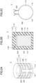
FIGS. 1A and 1B are drawings illustrating a latent heat storage unit according to a first embodiment; -
FIGS. 2A through 2C are drawings illustrating a latent heat storage unit according to a second embodiment; and -
FIG. 3 is an axonometric view illustrating a latent heat storage unit according to a third embodiment. - In the following, the embodiment will be described with reference to the accompanying drawings. In the specification and drawings, elements having substantially the same functional configuration may be referred to by the same reference numerals, and duplicate descriptions thereof may be omitted.
- The following paragraphs will describe a first embodiment. The first embodiment is directed to a latent heat storage unit.
FIGS. 1A and 1B are drawings illustrating the latent heat storage unit according to the first embodiment.FIG. 1A is a perspective view, andFIG. 1B is a cross-sectional view. - As illustrated in
FIGS. 1A and 1B , a latentheat storage unit 1 according to the first embodiment includes aceramic part 110 made of a polycrystalline body and ametal part 120. - A closed
space 113 is formed in theceramic part 110. The shape of theceramic part 110 and the closedspace 113 is cylindrical. Theceramic part 110 includes, for example, acontainer 111 and alid 112. Thecontainer 111 has a cylindrical shape with one end (upper end) open and the other end (lower end) closed. Afemale thread 111A is formed on the inner wall surface at the upper end of thecontainer 111. Thelid 112 closes the opening of thecontainer 111. Amale thread 112A screwed to thefemale thread 111A is formed in thelid 112. - The
ceramic part 110 may contain boron nitride (BN), boron carbide (B4C), aluminum nitride (AlN), a composite of aluminum nitride and boron nitride, silicon nitride (Si3N4), silicon carbide (SiC), or any combination thereof. Theceramic part 110 may be made of boron nitride, boron carbide, aluminum nitride, a composite of aluminum nitride and boron nitride (composite ceramic), silicon nitride, silicon carbide, or any combination thereof. - The
ceramic part 110 may contain borides. Theceramic part 110 may be made of borides. The borides may be, for example, titanium boride (TiB2), zirconium boride (ZrB2), hafnium boride (HfB2), vanadium boride (VB2), niobium boride (NbB2), tantalum boride (TaB2), lanthanum boride (LaB6), or any combination thereof. - The
metal part 120 is provided in the closedspace 113. In other words, themetal part 120 is encapsulated in theceramic part 110. It can also be said that themetal part 120 is airtightly covered by theceramic part 110. A plurality ofmetal parts 120 may alternatively be provided in theceramic part 110. Themetal part 120 contains boron (B). For example, the main component of themetal part 120 is boron. Themetal part 120 contains 50% or more boron by mass. Themetal part 120 may be made of boron having a purity of 50 mass% or more. More preferably, themetal part 120 contains 80% or more boron by mass, and is made of boron having a purity of 80 mass% or more. Yet more preferably, themetal part 120 contains 99% or more boron by mass, or is made of boron having a purity of 99 mass% or more. Themetal part 120 may contain silicon (Si), aluminum (Al), iron (Fe), copper (Cu), cobalt (Co), or any combination thereof in a total ratio of less than 20 mass%. - When the
metal part 120 is composed of 80% boron by mass and 20% silicon by mass, for example, the phase change temperature of themetal part 120 is 1900 °C or less. When themetal part 120 is composed of 80% boron by mass and 20% iron by mass, the phase change temperature of themetal part 120 is 1900 °C or less. When themetal part 120 is composed of 80% boron by mass and 20% copper by mass, the phase change temperature of themetal part 120 is 1100 °C or less. When themetal part 120 is composed of 80% boron by mass and 20% cobalt by mass, the phase change temperature of themetal part 120 is 1800 °C or less. - Although boron has several allotropes (α-rhombohedral, β-rhombohedral, β-tetragonal, etc.), the boron used in the
metal part 120 is, for example, β-rhombohedral boron, which is the most stable boron in the standard state. - The volume of the closed
space 113 is preferably larger than that of themetal part 120. This is because themetal part 120 changes from solid to liquid during the use of the latentheat storage unit 1, and themetal part 120 expands during this phase change, as will be described later. - The melting point of β-rhombohedral boron is 2180 °C. When the main component of
metal part 120 is β-rhombohedral boron, a phase change occurs between the solid and the liquid at about 2180 °C. At around this temperature, theceramic part 110 made of a polycrystalline body is chemically stable. Because of this, regardless of whether themetal part 120 is solid or liquid, theceramic part 110 is capable of confining themetal part 120 in the closedspace 113. Moreover, even when used at high temperature, chemical changes such as oxidation are not likely to occur in theceramic part 110. The melting point of themetal part 120 is, for example, 1100 °C or higher. The melting point of themetal part 120 is preferably 1400 °C or higher, more preferably 1700 °C or higher, and yet more preferably 2000 °C or higher. When themetal part 120 contains silicon or the like in addition to boron, it may suffice for the melting point of themetal part 120 to be lower than 2180 °C. The melting point of themetal part 120 may be measured by differential thermal analysis (DTA) or differential scanning calorimetry (DSC), for example. - In the latent
heat storage unit 1, since themetal part 120 functions as a phase change material (PCM) and themetal part 120 contains boron, the phase change temperature of themetal part 120 between solid and liquid is high, which allows a larger latent heat to be stored. The latent heat stored in the latentheat storage unit 1 may be used for direct power generation by thermophotovoltaic (TPV), for example. The latentheat storage unit 1 may be used as a thermal light source in a range of about 2100 °C to 2400 °C for power generation by thermophotovoltaic, for example. - The heat of fusion per unit mass of boron is at least 10 times that of aluminum, which greatly improves the thermal energy density.
- The material of the
ceramic part 110 will now be described in detail. - From the viewpoint of reactivity with boron contained in the
metal part 120 at a high temperature, boron nitride, boron carbide, aluminum nitride, and a composite of aluminum nitride and boron nitride are more preferable as the material of theceramic part 110. - As boron nitride, hexagonal phase boron nitride is preferable. Boron nitride has excellent processability.
- A composite of boron nitride and aluminum nitride (composite ceramic) has stability and high thermal conductivity as a sintered body. A composite of boron nitride and aluminum nitride has higher hardness and mechanical strength than hexagonal phase boron nitride. A sintered body of a composite of boron nitride and aluminum nitride has excellent processability. The ratio of boron nitride and aluminum nitride in the composite of boron nitride and aluminum nitride is not limited. The hardness and mechanical strength of the composite material change according to this ratio. The microstructure of the composite material is a mixture of aluminum nitride polyhedron (tetracaidecahedron) grains and plate-shaped boron nitride grains. The higher the proportion of plate-shaped boron nitride grains, the better the workability.
- An example of a material of the
ceramic part 110 is boride. As the boride, titanium boride, zirconium boride, hafnium boride, vanadium boride, niobium boride, and tantalum boride are preferable. These materials, which have conductivity with a specific resistance of about 10-7 Ω · m to 10-8 Ω · m and generate heat when energized, are usable as heaters. When theceramic part 110 includes titanium boride, zirconium boride, hafnium boride, vanadium boride, niobium boride, or tantalum boride, theceramic part 110 possesses the functions to protect and heat themetal part 120, and readily enables the realization of a higher heat storage density. In addition, theceramic part 110 including titanium boride, zirconium boride, hafnium boride, vanadium boride, niobium boride, or tantalum boride serves to achieve the size reduction of a system when using an electric thermal energy storage (ETES) system which stores heat by directly utilizing surplus electric power. - The
ceramic part 110 may have a seamless structure. Theceramic part 110 may not have a joint section extending to theclosed space 113, for example. Moreover, thefemale thread 111A of thecontainer 111 and themale thread 112A of thelid 112 need not be formed, and thelid 112 may be configured to snugly fit into thecontainer 111. - A second embodiment will be described below. The second embodiment is directed to a latent heat storage unit.
FIGS. 2A through 2C are drawings illustrating a latent heat storage unit according to the second embodiment.FIG. 2A is an axonometric view, andFIG. 2B is a cross-sectional view.FIG. 2C is a top view. - In a latent
heat storage unit 2 according to the second embodiment, as illustrated inFIG. 2 , twogrooves 115 are formed on the outer peripheral surface of theceramic part 110. The twogrooves 115 are arranged such as to form a substantially cylindrical shape. When viewed in a direction parallel to the long axis of thecolumnar metal part 120, each of thegrooves 115 alternately follows a clockwise winding path and a counterclockwise winding path to wind on the lateral surface of a cylinder, for example. Anelectric heating element 230 is provided in each of thegrooves 115. The latentheat storage unit 2 includes twoelectric heating elements 230. The twoelectric heating elements 230 are arranged such as to form a substantially cylindrical shape. Theelectric heating elements 230 contain, for example, graphite. Theelectric heating elements 230 may be made of graphite. Theelectric heating elements 230 are examples of heaters. - Other configurations of the second embodiment are the same as those of the first embodiment.
- The second embodiment provides the same advantageous effects as those of the first embodiment. The
electric heating elements 230 capable of heating themetal part 120 allows the electric energy applied from the outside to be converted into heat and stored in the latentheat storage unit 2. For example, utilizing theelectric heating elements 230 to generate heat by excess electric power allows the excess electric power to be stored as heat. The energy stored in the latentheat storage unit 2 may be supplied to a factory, office, or commercial building as energy in the form of heat, steam (pressure), or electric power (turbine power generation by steam pressure, or the like). - The inclusion of the
electric heating elements 230 in the latentheat storage unit 2 enables the reduction of energy loss. For example, when the electric heating elements and the latent heat storage unit are separated, transfer of generated heat from the electric heating elements to the latent heat storage unit requires the use of hot air currents or the like, which is likely to cause energy loss. This embodiment, however, allows for the reduction of such energy loss. - A third embodiment will be described below. The third embodiment is directed to a latent heat storage unit.
FIG. 3 is an axonometric view illustrating a latent heat storage unit according to the third embodiment. - As illustrated in
FIG. 3 , a latentheat storage unit 3 according to the third embodiment includes aceramic part 210 made of a polycrystalline body, ametal part 220, and anelectric heating element 330 capable of heating themetal part 220. Theelectric heating element 330 is provided in theceramic part 210. Theelectric heating element 330 is provided between the surface of theceramic part 210 and the surface of themetal part 220. Theelectric heating element 330 follows a winding path to form a substantially cylindrical shape. Along a direction parallel to the long axis of thecolumnar metal part 220, theelectric heating element 330 alternates clockwise winding and counterclockwise winding to follow a substantially cylindrical winding path, for example. Theelectric heating element 330 is an example of a heater. - When the main component of the
ceramic part 210 is aluminum nitride, for example, theelectric heating element 330 includes tungsten. Theelectric heating element 330 may include tungsten and aluminum nitride. In this case, in manufacturing the latentheat storage unit 3, tungsten powder is mixed with aluminum nitride powder, and organic components such as a solvent and a binder are added to prepare a resistor paste for example. The portions (circumferential portions) of theelectric heating element 330, which portions are perpendicular to the long axis of themetal part 220, may be formed by, for example, printing the resistor paste on the surfaces of ceramic green sheets. The portions of theelectric heating element 330 extending parallel to the long axis of themetal part 220 may be formed by, for example, filling, with the resistor paste, through holes formed through the ceramic green sheets. The resistivity of theelectric heating element 330 may be adjusted according to the proportion of aluminum nitride. One or more of silicon oxide, magnesium oxide, calcium carbonate, or the like may be added to the resistor paste. These inorganic components allow for the formation of a liquid phase or a complex oxide phase during firing, thereby improving the adhesion strength of theelectric heating element 330 to theceramic part 210 and improving the stability of the resistivity. - When the main component of the
ceramic part 210 is boron nitride, for example, theelectric heating element 330 contains lanthanum boride. Theelectric heating element 330 may contain lanthanum boride and boron nitride. In this case, in manufacturing the latentheat storage unit 3, for example, lanthanum boride powder is mixed with boron nitride powder, and organic components such as a solvent and a binder are added to prepare a resistor paste. The portions (circumferential portions) of theelectric heating element 330, which portions are perpendicular to the long axis of themetal part 220, may be formed by, for example, printing the resistor paste on the surfaces of ceramic green sheets. The portions of theelectric heating element 330 extending parallel to the long axis of themetal part 220 may be formed by, for example, filling, with the resistor paste, through holes formed through the ceramic green sheets. The resistivity of theelectric heating element 330 may be adjusted according to the proportion of boron nitride. One or more of silicon oxide, magnesium oxide, calcium carbonate, or the like may be added to the resistor paste. These inorganic components allow for the formation of a liquid phase or a complex oxide phase during calcination, thereby improving the adhesion strength of theelectric heating element 330 to theceramic part 210 and improving the stability of the resistivity. - The third embodiment provides the same advantageous effects as those of the second embodiment.
- According to the present disclosure, at least one embodiment enables the storage of larger latent heat.
- Although the preferred embodiments and the like have heretofore been described in detail, the present disclosure is not limited to the above-described embodiments and the like, and various variations and substitutions may be made to the above-described embodiments and the like without departing from the scope defined in the claims.
Claims (11)
- A latent heat storage unit (1, 2, 3) comprising:a ceramic part (110, 210) made of a polycrystalline body and having a closed space (111, 211) formed therein; anda metal part (120, 220) provided in the closed space (111, 211) and containing boron,wherein a melting point of the metal part (120, 220) is 1100 °C or higher.
- The latent heat storage unit (1, 2, 3) as claimed in claim 1, wherein the metal part (120, 220) contains 99% or more boron by mass.
- The latent heat storage unit (1, 2, 3) as claimed in claim 1 or 2, wherein a volume of the closed space (111, 211) is larger than a volume of the metal part (120, 220).
- The latent heat storage unit (1, 2, 3) as claimed in claim 1 or 2, wherein the ceramic part (110, 210) contains one or more selected from a group consisting of boron nitride, boron carbide, aluminum nitride, a composite of aluminum nitride and boron nitride, silicon nitride, and silicon carbide.
- The latent heat storage unit (1, 2, 3) as claimed in claim 1 or 2, wherein the ceramic part (110, 210) contains one or more borides.
- The latent heat storage unit (1, 2, 3) as claimed in claim 5, wherein the one or more borides are one or more selected from a group consisting of titanium boride, zirconium boride, hafnium boride, vanadium boride, niobium boride, tantalum boride, and lanthanum boride.
- The latent heat storage unit (1, 2, 3) as claimed in claim 1 or 2, wherein the ceramic part (110, 210) contains a material that generates heat when energized.
- The latent heat storage unit (2, 3) as claimed in claim 1 or 2, further comprising a heater (230, 330) configured to heat the metal part (120, 220) .
- The latent heat storage unit (2, 3) as claimed in claim 8, wherein the heater (230, 330) is provided in the ceramic part (110, 210).
- The latent heat storage unit (2, 3) as claimed in claim 8, wherein the heater (230, 330) contains either tungsten or molybdenum or both.
- The latent heat storage unit (2, 3) as claimed in claim 8, wherein the heater (230, 330) contains graphite.
Applications Claiming Priority (1)
| Application Number | Priority Date | Filing Date | Title |
|---|---|---|---|
| JP2023124144A JP2025020642A (en) | 2023-07-31 | 2023-07-31 | Latent heat storage material |
Publications (1)
| Publication Number | Publication Date |
|---|---|
| EP4502101A1 true EP4502101A1 (en) | 2025-02-05 |
Family
ID=92106986
Family Applications (1)
| Application Number | Title | Priority Date | Filing Date |
|---|---|---|---|
| EP24191254.2A Pending EP4502101A1 (en) | 2023-07-31 | 2024-07-26 | Latent heat storage unit |
Country Status (3)
| Country | Link |
|---|---|
| US (1) | US20250044042A1 (en) |
| EP (1) | EP4502101A1 (en) |
| JP (1) | JP2025020642A (en) |
Citations (4)
| Publication number | Priority date | Publication date | Assignee | Title |
|---|---|---|---|---|
| JP2015048393A (en) | 2013-08-30 | 2015-03-16 | 株式会社金星 | Heat reservoir |
| WO2015132305A1 (en) * | 2014-03-05 | 2015-09-11 | Universidad Politécnica de Madrid | Electric energy storage system |
| JP2021031507A (en) | 2019-08-14 | 2021-03-01 | 国立大学法人東海国立大学機構 | Composite structure, method for manufacturing composite structure, and method for heat storage |
| US20230140947A1 (en) * | 2020-03-18 | 2023-05-11 | DEUTSCHES ZENTRUM FüR LUFT-UND RAUMFAHRT E.V. | Heat storage device |
Family Cites Families (6)
| Publication number | Priority date | Publication date | Assignee | Title |
|---|---|---|---|---|
| US1433010A (en) * | 1921-07-21 | 1922-10-24 | Hogan George Lewis | Heat-storage battery |
| US7642205B2 (en) * | 2005-04-08 | 2010-01-05 | Mattson Technology, Inc. | Rapid thermal processing using energy transfer layers |
| FR3052549B1 (en) * | 2016-06-10 | 2019-10-11 | Hutchinson | HEAT ENERGY STORER EXCHANGER |
| TW202238061A (en) * | 2021-01-29 | 2022-10-01 | 澳大利亞商葛瑞夫艾特能源資產公司 | An energy storage device |
| US20240019217A1 (en) * | 2021-01-29 | 2024-01-18 | Graphite Energy (Assets) Pty Limited | Energy storage device |
| US12578152B2 (en) * | 2021-09-22 | 2026-03-17 | Wellhead Power Solutions, Llc | Thermal energy storage system |
-
2023
- 2023-07-31 JP JP2023124144A patent/JP2025020642A/en active Pending
-
2024
- 2024-07-22 US US18/779,783 patent/US20250044042A1/en active Pending
- 2024-07-26 EP EP24191254.2A patent/EP4502101A1/en active Pending
Patent Citations (4)
| Publication number | Priority date | Publication date | Assignee | Title |
|---|---|---|---|---|
| JP2015048393A (en) | 2013-08-30 | 2015-03-16 | 株式会社金星 | Heat reservoir |
| WO2015132305A1 (en) * | 2014-03-05 | 2015-09-11 | Universidad Politécnica de Madrid | Electric energy storage system |
| JP2021031507A (en) | 2019-08-14 | 2021-03-01 | 国立大学法人東海国立大学機構 | Composite structure, method for manufacturing composite structure, and method for heat storage |
| US20230140947A1 (en) * | 2020-03-18 | 2023-05-11 | DEUTSCHES ZENTRUM FüR LUFT-UND RAUMFAHRT E.V. | Heat storage device |
Non-Patent Citations (1)
| Title |
|---|
| JIAO JIAN MENG ET AL: "High temperature interaction between Si-B alloys and Si3N4", CERAMICS INTERNATIONAL, vol. 47, no. 10, 30 January 2021 (2021-01-30), NL, pages 13837 - 13844, XP093232126, ISSN: 0272-8842, Retrieved from the Internet <URL:https://pdf.sciencedirectassets.com/271590/1-s2.0-S0272884221X00089/1-s2.0-S027288422100287X/main.pdf?hash=a955b1196bdfb6de66e1ca6cf1627e00d9b386140619f7ca9b97acd02f2821ba&host=68042c943591013ac2b2430a89b270f6af2c76d8dfd086a07176afe7c76c2c61&pii=S027288422100287X&tid=spdf-424525e7-8596-4860-a41d-5fc> DOI: 10.1016/j.ceramint.2021.01.249 * |
Also Published As
| Publication number | Publication date |
|---|---|
| US20250044042A1 (en) | 2025-02-06 |
| JP2025020642A (en) | 2025-02-13 |
Similar Documents
| Publication | Publication Date | Title |
|---|---|---|
| EP0338823B1 (en) | Solid electrolyte type fuel cells | |
| JP6306510B2 (en) | High temperature or fuel cell electrochemical system with improved thermal management | |
| US4555358A (en) | Electrically conductive sintered ceramics and ceramic heaters | |
| BR102013012938B1 (en) | COMPOSITION OF BOLDING ALLOY AND ELECTROCHEMICAL CELL | |
| US20180090726A1 (en) | Ceramic materials and seals for high temperature reactive material devices | |
| US20150256119A1 (en) | Electric energy storage system | |
| US20240011132A1 (en) | High-entropy metal/ceramic composite materials for harsh environments | |
| US20170137344A1 (en) | Enhanced homogenous catalyzed reactor systems | |
| JPWO2012102348A1 (en) | Ti3SiC2 material, electrode, spark plug, and manufacturing method thereof | |
| US20250044042A1 (en) | Latent heat storage unit | |
| CA2336695A1 (en) | Refractory and temperature-resistant composite material "refsic" | |
| US12046379B2 (en) | Nuclear reactor with an axially stratified fuel bed | |
| US20240379256A1 (en) | System and method for thermionic energy conversion | |
| US4166156A (en) | Secondary battery or cell with pyrolytic graphite coated graphite current collector | |
| US12523433B2 (en) | Heat storage device, power generator, and heat generator | |
| US4999262A (en) | Multilayer cathode current collector/container for a battery | |
| US20230384041A1 (en) | Latent heat storage | |
| JP3740544B2 (en) | Silicon carbide based heating element | |
| JP2025133475A (en) | heat storage device | |
| JP2025020626A (en) | Latent heat storage body and method for producing latent heat storage body | |
| Fergus et al. | Refractory metals, ceramics, and composites for high-temperature structural and functional applications | |
| JP2025020642A5 (en) | ||
| US20230384040A1 (en) | Latent heat storage | |
| JP2025020626A5 (en) | ||
| JPH05326000A (en) | Solid electrolyte fuel cell |
Legal Events
| Date | Code | Title | Description |
|---|---|---|---|
| PUAI | Public reference made under article 153(3) epc to a published international application that has entered the european phase |
Free format text: ORIGINAL CODE: 0009012 |
|
| STAA | Information on the status of an ep patent application or granted ep patent |
Free format text: STATUS: THE APPLICATION HAS BEEN PUBLISHED |
|
| AK | Designated contracting states |
Kind code of ref document: A1 Designated state(s): AL AT BE BG CH CY CZ DE DK EE ES FI FR GB GR HR HU IE IS IT LI LT LU LV MC ME MK MT NL NO PL PT RO RS SE SI SK SM TR |
|
| STAA | Information on the status of an ep patent application or granted ep patent |
Free format text: STATUS: REQUEST FOR EXAMINATION WAS MADE |
|
| 17P | Request for examination filed |
Effective date: 20250430 |