EP4502033A1 - Sealing device - Google Patents
Sealing device Download PDFInfo
- Publication number
- EP4502033A1 EP4502033A1 EP23780833.2A EP23780833A EP4502033A1 EP 4502033 A1 EP4502033 A1 EP 4502033A1 EP 23780833 A EP23780833 A EP 23780833A EP 4502033 A1 EP4502033 A1 EP 4502033A1
- Authority
- EP
- European Patent Office
- Prior art keywords
- sealing
- sealing apparatus
- sealing body
- natural rubber
- provisions
- Prior art date
- Legal status (The legal status is an assumption and is not a legal conclusion. Google has not performed a legal analysis and makes no representation as to the accuracy of the status listed.)
- Pending
Links
Images

Classifications
-
- C—CHEMISTRY; METALLURGY
- C08—ORGANIC MACROMOLECULAR COMPOUNDS; THEIR PREPARATION OR CHEMICAL WORKING-UP; COMPOSITIONS BASED THEREON
- C08L—COMPOSITIONS OF MACROMOLECULAR COMPOUNDS
- C08L15/00—Compositions of rubber derivatives
-
- F—MECHANICAL ENGINEERING; LIGHTING; HEATING; WEAPONS; BLASTING
- F16—ENGINEERING ELEMENTS AND UNITS; GENERAL MEASURES FOR PRODUCING AND MAINTAINING EFFECTIVE FUNCTIONING OF MACHINES OR INSTALLATIONS; THERMAL INSULATION IN GENERAL
- F16J—PISTONS; CYLINDERS; SEALINGS
- F16J15/00—Sealings
- F16J15/02—Sealings between relatively-stationary surfaces
- F16J15/06—Sealings between relatively-stationary surfaces with solid packing compressed between sealing surfaces
- F16J15/10—Sealings between relatively-stationary surfaces with solid packing compressed between sealing surfaces with non-metallic packing
- F16J15/104—Sealings between relatively-stationary surfaces with solid packing compressed between sealing surfaces with non-metallic packing characterised by structure
-
- C—CHEMISTRY; METALLURGY
- C08—ORGANIC MACROMOLECULAR COMPOUNDS; THEIR PREPARATION OR CHEMICAL WORKING-UP; COMPOSITIONS BASED THEREON
- C08L—COMPOSITIONS OF MACROMOLECULAR COMPOUNDS
- C08L7/00—Compositions of natural rubber
-
- C—CHEMISTRY; METALLURGY
- C09—DYES; PAINTS; POLISHES; NATURAL RESINS; ADHESIVES; COMPOSITIONS NOT OTHERWISE PROVIDED FOR; APPLICATIONS OF MATERIALS NOT OTHERWISE PROVIDED FOR
- C09K—MATERIALS FOR MISCELLANEOUS APPLICATIONS, NOT PROVIDED FOR ELSEWHERE
- C09K3/00—Materials not provided for elsewhere
- C09K3/10—Materials in mouldable or extrudable form for sealing or packing joints or covers
-
- F—MECHANICAL ENGINEERING; LIGHTING; HEATING; WEAPONS; BLASTING
- F16—ENGINEERING ELEMENTS AND UNITS; GENERAL MEASURES FOR PRODUCING AND MAINTAINING EFFECTIVE FUNCTIONING OF MACHINES OR INSTALLATIONS; THERMAL INSULATION IN GENERAL
- F16J—PISTONS; CYLINDERS; SEALINGS
- F16J15/00—Sealings
- F16J15/002—Sealings comprising at least two sealings in succession
-
- F—MECHANICAL ENGINEERING; LIGHTING; HEATING; WEAPONS; BLASTING
- F16—ENGINEERING ELEMENTS AND UNITS; GENERAL MEASURES FOR PRODUCING AND MAINTAINING EFFECTIVE FUNCTIONING OF MACHINES OR INSTALLATIONS; THERMAL INSULATION IN GENERAL
- F16J—PISTONS; CYLINDERS; SEALINGS
- F16J15/00—Sealings
- F16J15/02—Sealings between relatively-stationary surfaces
- F16J15/021—Sealings between relatively-stationary surfaces with elastic packing
- F16J15/022—Sealings between relatively-stationary surfaces with elastic packing characterised by structure or material
-
- F—MECHANICAL ENGINEERING; LIGHTING; HEATING; WEAPONS; BLASTING
- F16—ENGINEERING ELEMENTS AND UNITS; GENERAL MEASURES FOR PRODUCING AND MAINTAINING EFFECTIVE FUNCTIONING OF MACHINES OR INSTALLATIONS; THERMAL INSULATION IN GENERAL
- F16J—PISTONS; CYLINDERS; SEALINGS
- F16J15/00—Sealings
- F16J15/02—Sealings between relatively-stationary surfaces
- F16J15/06—Sealings between relatively-stationary surfaces with solid packing compressed between sealing surfaces
- F16J15/10—Sealings between relatively-stationary surfaces with solid packing compressed between sealing surfaces with non-metallic packing
- F16J15/102—Sealings between relatively-stationary surfaces with solid packing compressed between sealing surfaces with non-metallic packing characterised by material
-
- F—MECHANICAL ENGINEERING; LIGHTING; HEATING; WEAPONS; BLASTING
- F16—ENGINEERING ELEMENTS AND UNITS; GENERAL MEASURES FOR PRODUCING AND MAINTAINING EFFECTIVE FUNCTIONING OF MACHINES OR INSTALLATIONS; THERMAL INSULATION IN GENERAL
- F16J—PISTONS; CYLINDERS; SEALINGS
- F16J15/00—Sealings
- F16J15/02—Sealings between relatively-stationary surfaces
- F16J15/06—Sealings between relatively-stationary surfaces with solid packing compressed between sealing surfaces
- F16J15/10—Sealings between relatively-stationary surfaces with solid packing compressed between sealing surfaces with non-metallic packing
- F16J15/12—Sealings between relatively-stationary surfaces with solid packing compressed between sealing surfaces with non-metallic packing with metal reinforcement or covering
- F16J15/121—Sealings between relatively-stationary surfaces with solid packing compressed between sealing surfaces with non-metallic packing with metal reinforcement or covering with metal reinforcement
- F16J15/122—Sealings between relatively-stationary surfaces with solid packing compressed between sealing surfaces with non-metallic packing with metal reinforcement or covering with metal reinforcement generally parallel to the surfaces
-
- F—MECHANICAL ENGINEERING; LIGHTING; HEATING; WEAPONS; BLASTING
- F16—ENGINEERING ELEMENTS AND UNITS; GENERAL MEASURES FOR PRODUCING AND MAINTAINING EFFECTIVE FUNCTIONING OF MACHINES OR INSTALLATIONS; THERMAL INSULATION IN GENERAL
- F16J—PISTONS; CYLINDERS; SEALINGS
- F16J15/00—Sealings
- F16J15/16—Sealings between relatively-moving surfaces
- F16J15/166—Sealings between relatively-moving surfaces with means to prevent the extrusion of the packing
-
- C—CHEMISTRY; METALLURGY
- C08—ORGANIC MACROMOLECULAR COMPOUNDS; THEIR PREPARATION OR CHEMICAL WORKING-UP; COMPOSITIONS BASED THEREON
- C08L—COMPOSITIONS OF MACROMOLECULAR COMPOUNDS
- C08L2312/00—Crosslinking
-
- C—CHEMISTRY; METALLURGY
- C09—DYES; PAINTS; POLISHES; NATURAL RESINS; ADHESIVES; COMPOSITIONS NOT OTHERWISE PROVIDED FOR; APPLICATIONS OF MATERIALS NOT OTHERWISE PROVIDED FOR
- C09K—MATERIALS FOR MISCELLANEOUS APPLICATIONS, NOT PROVIDED FOR ELSEWHERE
- C09K2200/00—Chemical nature of materials in mouldable or extrudable form for sealing or packing joints or covers
- C09K2200/02—Inorganic compounds
- C09K2200/0204—Elements
- C09K2200/0208—Carbon
-
- C—CHEMISTRY; METALLURGY
- C09—DYES; PAINTS; POLISHES; NATURAL RESINS; ADHESIVES; COMPOSITIONS NOT OTHERWISE PROVIDED FOR; APPLICATIONS OF MATERIALS NOT OTHERWISE PROVIDED FOR
- C09K—MATERIALS FOR MISCELLANEOUS APPLICATIONS, NOT PROVIDED FOR ELSEWHERE
- C09K2200/00—Chemical nature of materials in mouldable or extrudable form for sealing or packing joints or covers
- C09K2200/02—Inorganic compounds
- C09K2200/0243—Silica-rich compounds, e.g. silicates, cement, glass
- C09K2200/0247—Silica
-
- C—CHEMISTRY; METALLURGY
- C09—DYES; PAINTS; POLISHES; NATURAL RESINS; ADHESIVES; COMPOSITIONS NOT OTHERWISE PROVIDED FOR; APPLICATIONS OF MATERIALS NOT OTHERWISE PROVIDED FOR
- C09K—MATERIALS FOR MISCELLANEOUS APPLICATIONS, NOT PROVIDED FOR ELSEWHERE
- C09K2200/00—Chemical nature of materials in mouldable or extrudable form for sealing or packing joints or covers
- C09K2200/06—Macromolecular organic compounds, e.g. prepolymers
- C09K2200/0607—Rubber or rubber derivatives
-
- H—ELECTRICITY
- H01—ELECTRIC ELEMENTS
- H01M—PROCESSES OR MEANS, e.g. BATTERIES, FOR THE DIRECT CONVERSION OF CHEMICAL ENERGY INTO ELECTRICAL ENERGY
- H01M8/00—Fuel cells; Manufacture thereof
- H01M8/04—Auxiliary arrangements, e.g. for control of pressure or for circulation of fluids
- H01M8/04082—Arrangements for control of reactant parameters, e.g. pressure or concentration
- H01M8/04201—Reactant storage and supply, e.g. means for feeding, pipes
- H01M8/04216—Reactant storage and supply, e.g. means for feeding, pipes characterised by the choice for a specific material, e.g. carbon, hydride, absorbent
-
- Y—GENERAL TAGGING OF NEW TECHNOLOGICAL DEVELOPMENTS; GENERAL TAGGING OF CROSS-SECTIONAL TECHNOLOGIES SPANNING OVER SEVERAL SECTIONS OF THE IPC; TECHNICAL SUBJECTS COVERED BY FORMER USPC CROSS-REFERENCE ART COLLECTIONS [XRACs] AND DIGESTS
- Y02—TECHNOLOGIES OR APPLICATIONS FOR MITIGATION OR ADAPTATION AGAINST CLIMATE CHANGE
- Y02E—REDUCTION OF GREENHOUSE GAS [GHG] EMISSIONS, RELATED TO ENERGY GENERATION, TRANSMISSION OR DISTRIBUTION
- Y02E60/00—Enabling technologies; Technologies with a potential or indirect contribution to GHG emissions mitigation
- Y02E60/30—Hydrogen technology
- Y02E60/50—Fuel cells
Definitions
- the present invention relates to a sealing apparatus.
- Natural rubber a plant resource made from tree sap, has excellent mechanical strength and cold resistance, making it useful for applications to materials that require high sealability. Examples of applications in which such characteristics of natural rubber can be utilized include a hydrogen sealing material.
- diene-based rubbers such as natural rubber are generally prone to thermal degradation.
- stress relaxation occurs due to oxidative decomposition, and permanent deformation remains following compression release. This phenomenon is fatal to sealing products in which fluid is sealed with use of the restoring force of the rubber, as a result of which in order to apply natural rubber to hydrogen sealing materials, it is necessary to improve resistance to compression set in high-temperature air.
- Patent Literature 1 describes a sealing material for high-pressure hydrogen containers in fuel cell vehicles that can withstand fluctuation in pressure or temperature, and exemplifies natural rubber as one type of applicable rubber.
- Patent Literature 1 targets sealability in a high-temperature hydrogen atmosphere rather than a high-temperature air atmosphere
- the literature does not describe improvement in resistance to compression set of natural rubber in high-temperature air.
- the exposure time to high-temperature hydrogen gas is relatively short, for example, one hour, and furthermore, the literature does not describe any compounding information for rubber materials that can achieve the desired performance.
- Patent Literature 1 Japanese Patent Application Laid-Open No. 2008-57711
- the present invention provides a sealing apparatus that exhibits high mechanical strength under high pressures, and further has excellent cold resistance in low temperature ranges and resistance to compression set in high temperature ranges.
- the sealing apparatus is a sealing apparatus arranged between two members facing each other for sealing a space between the two members, wherein the sealing apparatus comprises a sealing body in contact with the space, and wherein the sealing body has a tensile strength of 10 MPa or more measured in accordance with the provisions of JIS K 6251: 2017, an elongation at break of 200% or more measured in accordance with the provisions of JIS K 6251: 2017, a TR10 temperature of -40°C or lower, measured in accordance with the provisions of JIS K 6261-4: 2017 in a low-temperature elastic recovery test, and a compression set at 100°C with an elapsed time of 70 hours in a shape of a G25 O-ring as described in the provisions of JIS B 2401-1: 2012, measured in accordance with the provisions of JIS K 6262: 2013, of 40% or less.
- the sealing body is annular.
- the sealing body is held by a backup ring.
- a cross-sectional shape of the sealing body is a projecting shape.
- the sealing body is arranged on a plate-like substrate, and the substrate is a plate made of metal or carbon.
- the substrate and the sealing body are bonded by an adhesive contained in the sealing body.
- the sealing body is in contact with hydrogen gas.
- the sealing body is in contact with liquid hydrogen.
- the sealing apparatus is a sealing apparatus for use in a hydrogen energy system.
- the sealing apparatus is a sealing apparatus arranged between two members facing each other for sealing a space between the two members, wherein the sealing apparatus comprises a sealing body in contact with the space, and wherein the sealing body is a vulcanized molded product of a rubber composition comprising (A) a natural rubber component selected from natural rubber and epoxy-modified natural rubber having an epoxidation degree of 1% or more and less than 50%, (B) a filler selected from carbon black and silica, (C) an organic peroxide-based crosslinking agent, and optionally (D) a silane coupling agent, provided that when the filler is carbon black, the rubber composition comprises epoxy-modified natural rubber having an epoxidation degree of 1% or more and less than 50%, and when the filler is silica, the rubber composition further comprises a silane coupling agent.
- a natural rubber component selected from natural rubber and epoxy-modified natural rubber having an epoxidation degree of 1% or more and less than 50%
- B a filler selected from carbon black
- the rubber composition further comprises (E) at least one additive selected from the group consisting of a crosslinking accelerator, an auxiliary, and an anti-aging agent.
- a sealing apparatus that exhibits high mechanical strength under high pressures, and further has excellent cold resistance in low temperature ranges and resistance to compression set in high temperature ranges, is provided.
- the room temperature described below shall be within a range of 23°C ⁇ 2°C.
- the sealing apparatus according to the present embodiment is a sealing apparatus arranged between two members facing each other for sealing a space between the two members, and comprises a sealing body in contact with the space.
- the sealing apparatus according to the present embodiment is preferably used in a hydrogen energy system, in which the sealing body is in contact with hydrogen gas or liquid hydrogen, and the sealing apparatus is used as a hydrogen gas seal or liquid hydrogen seal.
- FIG. 1 shows an example of an embodiment of the sealing apparatus comprising such a sealing body.
- a sealing apparatus 1 shown in Fig. 1 is mounted in a mounting groove 4 (mounting portion) arranged in one member 2 of two members 2 and 3 facing each other and is in close contact with the other member 3, thereby sealing between the two members 2 and 3.
- the sealing apparatus 1 has a sealing ring 11 (ring packing made of rubber) made of rubbery elastic body, a first backup ring 21 (backup ring) arranged on a low-pressure side L of the sealing ring 11, and a second backup ring 31 arranged between the sealing ring 11 and the first backup ring 21.
- the two members 2 and 3 are, for example, high-pressure hydrogen pipes for a fuel cell, which are connected to each other, and on an outer peripheral side of a seal housing portion in one piping member 2, a seal housing portion of the other piping member 3 is arranged, and the sealing apparatus 1 is mounted in the annular mounting groove 4 arranged on the outer peripheral side of the seal housing portion of the piping member 2, and is in close contact with an inner peripheral surface of the seal housing portion of the other piping member 3.
- Sealed fluid is high-pressure hydrogen gas which attempts to flow from a high-pressure side H to the low-pressure side L.
- the first backup ring 21 for use is a backup ring made of nylon (product name). Nylon is one of resin materials, which is difficult for gas to pass through.
- the second backup ring 31 for use is a backup ring made of a material that is softer than the first backup ring 21, such as a PTFE resin.
- rings with ends are often used, in which one location on the circumference is cut in order to be easily incorporated, but when gas leakage is taken into consideration, they are preferably endless types without a cut.
- the sealing ring 11 corresponds to a sealing body of the sealing apparatus according to the present invention.
- the sealing ring 11 is annularly formed, and is held by the first and second backup rings 21 and 31.
- a material of the sealing ring 11 is the same as the material that forms the sealing body, which will be described later, and the sealing ring 11 exhibits the characteristics of the sealing body, which will be described later.
- the mounting groove 4 is basically formed as a space with a rectangular cross section, but a high-pressure side mounting part 4a for mounting the sealing ring 11 at the bottom of the groove, is formed as a flat surface forming a cylindrical surface. Also a low-pressure side mounting part 4b for mounting the first and second backup rings 21 and 31, which is continuous along with the low-pressure side L of the high-pressure side mounting part 4a, is formed as an inclined surface forming a conical surface so that a gap (gap in the radial direction) between the two members 2 and 3 gradually narrows from the high-pressure side H to the low-pressure side L, i.e., so that a depth of the mounting groove 4 gradually becomes shallower, and is formed as an inclined bottom surface 4c.
- first and second backup rings 21 and 31 mounted on the low-pressure side mounting part 4b are each basically formed in a rectangular cross sectional shape, but its inner peripheral surface, corresponding to the inclined bottom surface 4c, is formed as an inclined surface forming a conical surface so that the inner diameter dimension gradually increases from the high pressure side H to the low pressure side L, and is formed as inclined surfaces 21a and 31a.
- the sealing apparatus 1 having such a configuration, when pressure P acts from the right-hand side of Fig. 1 , the sealing ring 11 is pressed against the second backup ring 31 on the low pressure side, but this second backup ring 31 is made of a PTFE resin, which is softer than the first backup ring 21 made of nylon. Therefore, it is designed to be possible to inhibit the sealing ring 11 from being repeatedly pressed against the hard material and being damaged upon generation of alternating pressure or the like. Also the second backup ring 31 that is made of a PTFE resin, which is a soft material, is prone to projection, but the first backup ring 21 that is made of nylon, which is a hard material, prevents projection.
- the mounting groove 4 is also arranged with the inclined bottom surface 4c that gradually narrows a gap between the two members 2 and 3 from the high pressure side H to the low pressure side L, and both backup rings 21 and 31 are arranged with the inclined surfaces 21a and 31a, respectively, corresponding to the inclined bottom surface 4c on their inner peripheral surfaces. Therefore, when a sealed fluid pressure acts on both backup rings 21 and 31 via the sealing ring 11, both backup rings 21 and 31 are compressed in a manner to be forced into a narrow space and come into strong, intimate contact with the mating surfaces.
- the backup ring 21 is also formed of nylon, which is difficult for gas to permeate. Therefore, from this point of view as well, it can be expected that leakage whereby high-pressure hydrogen gas that is sealed fluid permeates the backup ring 21, will be effectively reduced. Furthermore, since a width dimension in the radial direction of the backup ring 21 is smaller than a width dimension in the radial direction of the second backup ring 31, the permeation area is set small. Therefore, from this point of view as well, it is possible to effectively seal the high-pressure hydrogen gas, which is sealed fluid.
- the sealing apparatus 1 may also be used not only for a cylindrical gap between the two members, but also for a flat gap, i.e., a gap between end faces.
- Fig. 2 shows an example of the embodiment of such a sealing apparatus.
- the first backup ring 21 or second backup ring 31 is aligned in the axial direction in order to seal a cylindrical gap between one piping member 2 and the other piping member 3, while in an upper sealing apparatus 1B in Fig. 2 , the first backup ring 21 or second backup ring 31 is aligned in the radial direction in order to seal a flat gap between one piping member 2 and the other piping member 3. Arranging them in such a double manner further enables reducing leakage to the outside.
- FIG. 3 shows an example of the sealing apparatus according to another embodiment of the present invention.
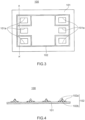
- a sealing apparatus 100 shown in Fig. 3 is a sealing member for a separator that is stacked on both sides of an electrolyte membrane/electrode assembly (hereinafter referred to as MEA) in a general fuel cell, i.e., a cell seal for a fuel cell.
- MEA electrolyte membrane/electrode assembly
- Such a cell seal for a fuel cell is arranged between a separator and an MEA, which are two members facing each other to tightly seal a space between the separator and MEA (not shown).
- a separator of a fuel cell needs to supply fluid for a fuel cell (fuel gas containing hydrogen, oxidant gas containing oxygen, and the like) to MEA without leakage to the outside, and an endless gasket serves to seal such fluid for a fuel cell within a space surrounded by the gasket.
- FIG. 4 shows a schematic cross section of the sealing apparatus 100 along a line AA' in Fig. 3 , in which a gasket 102 is formed with four projecting portions that project from the surface of the substrate 101.
- the gasket 102 has a base portion 102a bonded to the surface of the substrate 101 and a seal lip portion 102b projecting in a mountain shape from the base portion 102a. Note that, on the line AA' in Fig. 3 , there is a location (not shown) through which a molding material of the gasket 102 flows in and out upon molding of the gasket 102.
- the substrate 101 which is, for example, a thin plate including a metal plate such as stainless steel, a carbon plate or the like is used.
- the substrate 101 and the gasket 102 are bonded via an adhesive layer or by an adhesive contained in the gasket 102.
- the sealing apparatus 100 may be an integrally molded cell seal in which a surface of the plate-like substrate 101 is integrally molded with the endless gasket 102 made of elastic material and extending along the surface of the substrate 101.
- the substrate 101 of such an integrally molded cell seal is a member included in a cell structure of a fuel cell that is integrally molded with the gasket 102, and examples of the substrate 101 include a separator, MEA, a gas diffusion layer (GDL), and the like.
- the gasket 102 corresponds to the sealing body of the sealing apparatus according to the present invention. As shown in Fig. 4 , the cross-sectional shape of the gasket 102 is a projecting shape. A material of the gasket 102 is the same as the material that forms the sealing body, which will be described later, and the gasket 102 exhibits the characteristics of the sealing body, which will be described later.
- the sealing body of the sealing apparatus is a vulcanized molded product of a rubber composition containing (A) a natural rubber component selected from natural rubber and epoxy-modified natural rubber having an epoxidation degree of 1% or more and less than 50%, (B) a filler selected from carbon black and silica, (C) an organic peroxide-based crosslinking agent, and optionally (D) a silane coupling agent, provided that when the filler is carbon black, the rubber composition contains epoxy-modified natural rubber having an epoxidation degree of 1% or more and less than 50%, and when the filler is silica, the rubber composition further contains a silane coupling agent.
- A a natural rubber component selected from natural rubber and epoxy-modified natural rubber having an epoxidation degree of 1% or more and less than 50%
- B a filler selected from carbon black and silica
- C an organic peroxide-based crosslinking agent
- D a silane coupling agent
- sealing body that is less likely to crack even under high pressures, has high elastic recovery even in low temperature ranges, and has small compression set at high temperature ranges, which are all characteristics required for a hydrogen sealing material, as a result of which it is possible to realize a sealing apparatus that exhibits high mechanical strength under high pressures, and further has excellent cold resistance at low temperature ranges and resistance to compression set at high temperature ranges.
- a shape of the sealing body is not particularly limited, and can be formed into any shape depending on its application.
- it may be a sealing member in sheet form with a cross-sectional shape of a square, rectangle, disk, or the like., or an annular sealing member such as an O-ring or a square ring, and these annular portions may be formed in a portion of the sealing body.
- the natural rubber component for use is natural rubber that has not been chemically modified at all, or natural rubber that has been epoxy-modified with a diene portion having an epoxidation degree of 1% or more and less than 50%.
- Natural rubber is rubber refined from sap (latex) of natural trees, and is diene-based rubber that is different from synthetic rubber that was chemically synthesized using petroleum, naphtha, and the like as raw materials.
- a diene portion of the natural rubber can be epoxidized by a reaction between formic acid and hydrogen peroxide solution.
- the epoxy-modified natural rubber has an epoxidation degree of 1% or more and less than 50%, preferably has an epoxidation degree of 10% or more and 40% or less, and more preferably has an epoxidation degree of 20% or more and 30% or less.
- the natural rubber and the epoxy-modified natural rubber may be used singly or in combinations of two or more thereof. Using such natural rubber enables improving the mechanical properties of the sealing body. Also the natural rubber and epoxy-modified natural rubber may be commercially available products. Examples of the commercially available natural rubber and epoxy-modified natural rubber include natural rubber "RSS No. 1" (imported product of TOYOTSU CHEMIPLAS CORPORATION), natural rubber having an epoxidation degree of 25% "ENR25" (imported product of Sanyo Trading Co., Ltd.).
- the rubber composition is compounded with a filler.
- the filler contained in the rubber composition can improve the mechanical strength and compression set of the resulting vulcanizate.
- carbon black and silica which are common reinforcing materials, are used.
- the fillers may be used singly or in combinations of two or more thereof.
- Carbon black can be appropriately selected from known materials, for example, hard carbon such as Super Abrasion Furnace (SAF) carbon black, Intermediate Super Abrasion Furnace (ISAF) carbon black, High Abrasion Furnace (HAF) carbon black, and Easy Processing Channel (EPC) carbon black, as well as soft carbon such as eXtra Conductive Furnace (XCF) carbon black, Fast Extruding Furnace (FEF) carbon black, General Purpose Furnace (GPF) carbon black, High Modulus Furnace (HMF) carbon black, Semi-Reinforcing Furnace (SRF) carbon black, Fine Thermal (FT) carbon black, and Medium Thermal (MT) carbon black.
- hard carbon such as Super Abrasion Furnace (SAF) carbon black, Intermediate Super Abrasion Furnace (ISAF) carbon black, High Abrasion Furnace (HAF) carbon black, and Easy Processing Channel (EPC) carbon black
- soft carbon such as eXtra Conductive Furnace (XCF) carbon black, Fast Ex
- Examples of commercially available carbon black include "Vulcan (registered trademark) 3L” (HAF carbon) manufactured by Cabot Corporation and the like.
- the content of carbon black is not particularly limited, but is preferably 1 part by mass or more and 100 parts by mass or less, and more preferably 25 parts by mass or more and 75 parts by mass or less, relative to 100 parts by mass of the natural rubber component.
- the carbon black may be used singly or in combinations of two or more thereof.
- Silica may be appropriately selected from any known material, but it preferably has favorable kneading workability.
- Examples of commonly used silica include dry-process silica produced by a thermal decomposition method of halogenated silicic acid or organic silicon compounds, or by a method for heating and reducing silica sand and oxidizing vaporized SiO with air, or the like, and wet-process silica produced by a thermal decomposition method of sodium silicate, or the like.
- Examples of commercially available silica products include, for example, "Ultrasil (registered trademark) 360" manufactured by Evonik Japan Co., Ltd., and the like.
- the content of silica is not particularly limited, but is preferably 1 part by mass or more and 100 parts by mass or less, and more preferably 25 parts by mass or more and 75 parts by mass or less, relative to 100 parts by mass of the natural rubber component.
- the silica may be used singly or in combinations of two or more thereof.
- the organic peroxide-based crosslinking agent is used as a crosslinking agent that forms a peroxide crosslink of the natural rubber component.
- the organic peroxide-based crosslinking agent as the crosslinking agent, excellent resistance to compression set is imparted to the sealing body.
- organic peroxide-based crosslinking agents include, for example, dicumyl peroxide, cumene hydroperoxide, p-methane hydroperoxide, 2,5-dimethylhexane-2,5-dihydroperoxide, di-tert-butyl peroxide, benzoyl peroxide, m-toluyl peroxide, 2,5-dimethyl-2,5-bis(tert-butylperoxy)hexane, 2,5-dimethyl-2,5-bis(tert-butylperoxy)-3-hexyne, 1,3-bis(tert-butylperoxyisopropyl)benzene, 2,5-dimethyl-2,5-di(benzoylperoxy)hexane, 1,1,3,3-tetramethylbutylperoxy-2-ethylhexanoate, tert-butylperoxybenzoate, tert-butylperoxylaurate, di
- organic peroxide-based crosslinking agent for example, "Percumyl (registered trademark) D” manufactured by NOF CORPORATION and the like can be used.
- the content of the organic peroxide-based crosslinking agent is preferably 0.1 parts by mass or more and 10 parts by mass or less, and more preferably 1 part by mass or more and 5 parts by mass or less, relative to 100 parts by mass of the natural rubber component.
- the organic peroxide-based crosslinking agent may be used singly or in combinations of two or more thereof.
- a silane coupling agent is further compounded into the rubber composition.
- a silane coupling agent having a mercapto group, for example, 3-mercaptopropyltrimethoxysilane, 3-mercaptopropyltriethoxysilane, 3-mercaptopropyldiethoxymethoxysilane, 3-mercaptopropyltripropoxysilane, 3-mercaptopropyldipropoxymethoxysilane, 3-mercaptopropyltributoxysilane, 3-mercaptopropyldibutoxymethoxysilane, 3-mercaptopropylmethyldimethoxysilane, 3-mercaptopropyldimethylmethoxysilane, 3-mercaptopropylmethyldiethoxysilane, 3-mercaptopropyldimethylethoxysilane, 3-mercaptopropylmethyldipropoxysilane, 3-mercaptopropylmethyldipropoxysilane, 3-mercaptopropylmethyl
- silane coupling agent for example, "KBM-803" manufactured by Shin-Etsu Chemical Co., Ltd. and the like can be used.
- the content of the silane coupling agent is preferably 0.1 parts by mass or more and 10 parts by mass or less and more preferably 1 part by mass or more and 5 parts by mass or less, relative to 100 parts by mass of the natural rubber component.
- the silane coupling agent may be used singly or in combinations of two or more thereof.
- the rubber composition may contain other compounding components in addition to the above-described components, if necessary.
- the other compounding components include various additives such as a crosslinking accelerator, a plasticizer, an anti-aging agent, an auxiliary agent, a slip agent, an adhesive, lubricant, a flame retardant, a fungicide, and an antistatic agent. These additives may be used singly or in combinations of two or more thereof. Also, the compounding amount of these additives is not particularly limited as long as it does not impede the purpose and effect of the present invention, and an appropriate amount according to the compounding purpose can be compounded.
- the method for producing the sealing body is not particularly limited, and may be a method that includes, for example, appropriately compounding the above-described natural rubber component, filler, and organic peroxide-based crosslinking agent, as well as a silane coupling agent and various optional additives, which are compounded, if necessary, in a predetermined ratio, and then kneading them by using a kneading machine such as a single-screw extruder, a twin-screw extruder, a roll, a Banbury mixer, a kneader, or a high-shear mixer to produce a rubber composition.
- a kneading machine such as a single-screw extruder, a twin-screw extruder, a roll, a Banbury mixer, a kneader, or a high-shear mixer to produce a rubber composition.
- a kneading machine such as a single-
- the obtained rubber composition undergoes vulcanization molding to be able to produce a vulcanized molded product having a shape of the sealing body.
- the vulcanization molding of the rubber composition is generally performed by pressurized vulcanization at about 150 to 230°C for approximately 0.5 to 30 minutes using an injection molding machine, a compression molding machine, or the like.
- the rubber composition may also undergo secondary vulcanization, if necessary, in order to ensure that an inside of the vulcanized molded product is also vulcanized.
- the secondary vulcanization can generally be carried out by heating the rubber composition in an oven, or by steam heating, hot air heating, or the like at about 150 to 250°C for approximately 0.5 to 24 hours.
- the sealing body of the sealing apparatus has a tensile strength (tensile strength measured under the conditions of test specimen shape: dumbbell-shaped No. 6, rate: 500 mm/min, distance between marked lines: 20 ⁇ 0.5 mm, atmosphere: air, test temperature: room temperature), measured in accordance with the provisions of JIS K6251:2017 (the Japanese Industrial Standards created by modifying the technical content based on ISO37 (5th edition, 2011)), of 10 MPa or more and preferably 15 MPa or more. Also the sealing body has an elongation at break (elongation at break measured under the conditions of test specimen shape: dumbbell-shaped No.
- the sealing body having a tensile strength of 10 MPa or more and an elongation at break of 200% or more can provide a sealing apparatus comprising a sealing body that exhibits high mechanical strength even under high pressures.
- the sealing body of the sealing apparatus has a TR10 temperature in a low-temperature elastic recovery test (TR test) (TR10 temperature measured in the low-temperature elastic recovery test (TR test) under the conditions of test specimen shape: I-shaped as described in the provisions of JIS K6261-4: 2017, heat medium: ethanol, test temperature: - 70°C to 23°C), measured in accordance with the provisions of JIS K6261-4: 2017 (the Japanese Industrial Standards created by modifying the technical content based on ISO2921 (5th edition, 2011)), of -40°C or lower and preferably -60°C or lower.
- the temperature at TR10 is -40°C or lower, enables providing a sealing apparatus comprising a sealing body that has excellent cold resistance in low temperature ranges.
- the sealing body of the sealing apparatus has a compression set at 100°C with an elapsed time of 70 hours in a shape of G25 O-ring described in the provisions of JIS B 2401-1: 2012 (Japanese Industrial Standards created by modifying the technical content based on ISO3601-1 (4th edition, 2008)) (compression set measured under the conditions of compression plate: smooth stainless steel plate, test specimen shape: G25 O-ring as described in the provisions of JIS B 2401-1: 2012, spacer thickness: 2.30 mm, compression rate: 25%, atmosphere: air, test temperature: 100°C, exposure time: 70 hours, conditions when left stand after release: room temperature for 30 minutes), measured in accordance with the provisions of JIS K 6262:2013 (the Japanese Industrial Standards created by modifying the technical content based on ISO815-1 and ISO815-2 (both 1st editions, 2008)), of 40% or less and preferably 35% or less.
- the compression set under such conditions of 40% or less enables providing a sealing apparatus comprising a sealing body that has excellent
- the present invention relates to the following [1] to [7].
- the obtained rubber dough was fed into a roll kneader ("LABORTORY MILL", manufactured by Kansai Roll Co., Ltd.), and passed therethrough with a roll gap of 1.5 to 2.5 mm five times followed by being passed therethrough with a roll gap of 1 mm ten times to fabricate a rubber composition.
- a roll kneader manufactured by Kansai Roll Co., Ltd.
- the rubber composition obtained was crosslinked by hot press at 170°C using a press machine ("80 TON PRESS", manufactured by Hokutan Kikai Kogyo Kabushiki Kaisha), and was crosslinked for a time 1.5 times a t90 (90% crosslinked time) to undergo pressurized vulcanization (primary vulcanization) and to fabricate a test piece A.
- the rubber composition obtained was crosslinked by hot press at 170°C using a press machine ("50 TON KV PRESS", manufactured by KODAISHOJI Co., LTD.), and was crosslinked for a time 1.5 times a t90 (90% crosslinked time) to undergo pressurized vulcanization (primary vulcanization) and to fabricate a test piece B.
- the tensile strength and elongation at break of the test piece A were measured using a tensile tester (Strograph (registered trademark) AE, manufactured by Toyo Seiki Seisaku-sho, Ltd.) under the following test conditions in accordance with the provisions of JIS K 6251: 2017. The results are shown in Table 1.
- test piece A underwent a low-temperature elastic recovery test (TR test) under the following test conditions in accordance with the provisions of JIS K6261-4: 2017 using a TR tester "No. 145-L", manufactured by YASUDA SEIKI SEISAKUSHO, LTD.), and a temperature at TR10 was measured.
- TR test low-temperature elastic recovery test
- test piece B For the test piece B, a compression set was measured under the following test conditions in accordance with the provisions of JIS K 6262: 2013. The results are shown in Table 1.
- a rubber composition and respective test pieces A and B were fabricated in the same manner as in Example 1, except that natural rubber ("RSS No. 1", imported product of TOYOTSU CHEMIPLAS CORPORATION) was used instead of natural rubber having an epoxidation degree of 25%, a filler B (silica: trade name "Ultrasil (registered trademark) 360", manufactured by Evonik Japan Co., Ltd.) was used instead of the filler A, and 1 part by mass of a silane coupling agent (mercapto group-containing silane coupling agent: trade name "KBM-803", manufactured by Shin-Etsu Chemical Co., Ltd.) was further compounded, and then the above measurements were made. The results are shown in Table 1.
- a silane coupling agent mercapto group-containing silane coupling agent: trade name "KBM-803", manufactured by Shin-Etsu Chemical Co., Ltd.
- a rubber composition and respective test pieces A and B were fabricated in the same manner as in Example 1, except that natural rubber ("RSS No. 1", imported product of TOYOTSU CHEMIPLAS CORPORATION) instead of natural rubber having an epoxidation degree of 25% and 0.5 parts by mass of a crosslinking agent B (sulfur: trade name "Colloidal Sulfur A", manufactured by Tsurumi Chemical Industry Co., Ltd.) instead of the crosslinking agent A, were used, 1.5 parts by mass of a crosslinking accelerator A (N-cyclohexyl-2-benzothiazole sulfenamide: trade name "Noccela (registered trademark) CZ-G", manufactured by OUCHI SHINKO CHEMICAL CO., LTD.) and 1 part by mass of a crosslinking accelerator B (tetramethylthiuram disulfide: trade name "Noccela (registered trademark) TT-P", manufactured by OUCHI SHINKO CHEMICAL CO., LTD.) were further compound
- a rubber composition and respective test pieces A and B were fabricated in the same manner as in Example 1, except that natural rubber ("RSS No. 1", imported product of TOYOTSU CHEMIPLAS CORPORATION) was used instead of natural rubber having an epoxidation degree of 25%, and then the above measurements were made.
- RSS No. 1 imported product of TOYOTSU CHEMIPLAS CORPORATION
- a rubber composition and respective test pieces A and B were fabricated in the same manner as in Example 1, except that natural rubber ("ENR50", imported product of Sanyo Trading Co., Ltd.) having an epoxidation degree of 50% was used instead of natural rubber having an epoxidation degree of 25%, and then the above measurements were made.
- natural rubber (“ENR50", imported product of Sanyo Trading Co., Ltd.) having an epoxidation degree of 50% was used instead of natural rubber having an epoxidation degree of 25%, and then the above measurements were made.
- ERR50 imported product of Sanyo Trading Co., Ltd.
- Example 1 Example 2 Comparative Example 1 Comparative Example 2 Comparative Example 3
- Com parative Example 4 Rubber composition Natural rubber 100 100 100 100 100 Natural rubber having a degree of epoxidation of 25% 100 Natural rubber having a degree of epoxidation of 50% 100 Filler A 50 50 50 50 50 Filler B 50 50 Crosslinking agent A 2.5 2.5 2.5 2.5 2.5 2.5 2.5 Crosslinking agent B 0.5 Silane coupling agent 1 Crosslinking accelerator A 1.5 Crosslinking accelerator B 1 Auxiliary agent A 5 5 5 5 5 5 Auxiliary agent B 1 1 1 1 1 1 1 Anti-aging agent 2 2 2 2 2 2 2 2 2 2 2
- Mechanical strength Tensile strength [MPa] 23.8 15.8 26.9 23.9
- Examples 1 and 2 each exhibited the tensile strength of 10 MPa or more, the elongation at break of 200% or more, and the high mechanical strength even under high pressures. Also Examples 1 and 2 exhibited the temperature of TR10 in the low-temperature elastic recovery test of -40°C or lower, and further the compression set at 100°C with an elapsed time of 70 hours, of 40% or less, resulting in being excellent in the cold resistance in low temperature ranges and the resistance to compression set in high temperature ranges.
- Comparative Example 1 in which the sulfur crosslinking agent was used as the crosslinking agent, exhibited the compression set of higher than 40%, indicating the poor resistance to compression set.
- Comparative Example 2 in which carbon black was used as the filler and unmodified natural rubber was used as the natural rubber component, exhibited the compression set of higher than 40% and the poor resistance to compression set.
- Comparative Example 3 in which carbon black was used as the filler and natural rubber having an epoxidation degree of 50% was used as the natural rubber component, exhibited the compression set of 40% or less, but the TR10 temperature in the low-temperature elastic recovery test of higher than -40°C, indicating the poor cold resistance.
- Comparative Example 4 in which silica was used as the filler but no silane coupling agent was used, exhibited the compression set of higher than 40%, indicating the poor resistance to compression set.
Landscapes
- Engineering & Computer Science (AREA)
- General Engineering & Computer Science (AREA)
- Chemical & Material Sciences (AREA)
- Mechanical Engineering (AREA)
- Organic Chemistry (AREA)
- Health & Medical Sciences (AREA)
- Chemical Kinetics & Catalysis (AREA)
- Medicinal Chemistry (AREA)
- Polymers & Plastics (AREA)
- Materials Engineering (AREA)
- Gasket Seals (AREA)
- Compositions Of Macromolecular Compounds (AREA)
- Sealing Material Composition (AREA)
Abstract
Description
- The present invention relates to a sealing apparatus.
- In October 2020, the Japanese government declared that it would achieve carbon neutrality by 2050, reducing greenhouse gas emissions to zero overall. In terms of raw materials, switching from petroleum resources to plant resources that absorb carbon dioxide can contribute to carbon neutrality. Natural rubber, a plant resource made from tree sap, has excellent mechanical strength and cold resistance, making it useful for applications to materials that require high sealability. Examples of applications in which such characteristics of natural rubber can be utilized include a hydrogen sealing material.
- In a hydrogen society, which is expected to be a means of decarbonization, carbon dioxide is not emitted upon use of energy. Hydrogen stations and fuel cell vehicles have already been put into practical use in order to realize a hydrogen society, but there is a demand for sealing technology that can safely manage hydrogen without leaks at high pressures and over a wide temperature range. Therefore, combinations of hydrogen applications and natural rubber are expected to bring about a synergistic decarbonization effect, and to inhibit cracking under high pressures in sealing products and improve elasticity reduction (cold resistance) at low temperatures.
- However, diene-based rubbers such as natural rubber are generally prone to thermal degradation. When natural rubber is exposed to high-temperature air in a compressed state for a long period of time, stress relaxation occurs due to oxidative decomposition, and permanent deformation remains following compression release. This phenomenon is fatal to sealing products in which fluid is sealed with use of the restoring force of the rubber, as a result of which in order to apply natural rubber to hydrogen sealing materials, it is necessary to improve resistance to compression set in high-temperature air.
-
Patent Literature 1 describes a sealing material for high-pressure hydrogen containers in fuel cell vehicles that can withstand fluctuation in pressure or temperature, and exemplifies natural rubber as one type of applicable rubber. However, sincePatent Literature 1 targets sealability in a high-temperature hydrogen atmosphere rather than a high-temperature air atmosphere, the literature does not describe improvement in resistance to compression set of natural rubber in high-temperature air. Moreover, the exposure time to high-temperature hydrogen gas is relatively short, for example, one hour, and furthermore, the literature does not describe any compounding information for rubber materials that can achieve the desired performance. - Therefore, it is necessary to investigate a sealing material made of natural rubber that has high mechanical strength under high pressures, excellent cold resistance, and can further exhibit excellent resistance to compression set in high-temperature air for a long period of time.
- Patent Literature 1:
Japanese Patent Application Laid-Open No. 2008-57711 - The present invention provides a sealing apparatus that exhibits high mechanical strength under high pressures, and further has excellent cold resistance in low temperature ranges and resistance to compression set in high temperature ranges.
- The sealing apparatus according to an embodiment of the present invention is a sealing apparatus arranged between two members facing each other for sealing a space between the two members, wherein the sealing apparatus comprises a sealing body in contact with the space, and wherein the sealing body has a tensile strength of 10 MPa or more measured in accordance with the provisions of JIS K 6251: 2017, an elongation at break of 200% or more measured in accordance with the provisions of JIS K 6251: 2017, a TR10 temperature of -40°C or lower, measured in accordance with the provisions of JIS K 6261-4: 2017 in a low-temperature elastic recovery test, and a compression set at 100°C with an elapsed time of 70 hours in a shape of a G25 O-ring as described in the provisions of JIS B 2401-1: 2012, measured in accordance with the provisions of JIS K 6262: 2013, of 40% or less.
- In an embodiment of the present invention, the sealing body is annular.
- In an embodiment of the present invention, the sealing body is held by a backup ring.
- In an embodiment of the present invention, a cross-sectional shape of the sealing body is a projecting shape.
- In an embodiment of the present invention, the sealing body is arranged on a plate-like substrate, and the substrate is a plate made of metal or carbon.
- In an embodiment of the present invention, the substrate and the sealing body are bonded by an adhesive contained in the sealing body.
- In an embodiment of the present invention, the sealing body is in contact with hydrogen gas.
- In an embodiment of the present invention, the sealing body is in contact with liquid hydrogen.
- In an embodiment of the present invention, the sealing apparatus is a sealing apparatus for use in a hydrogen energy system.
- The sealing apparatus according to another embodiment of the present invention is a sealing apparatus arranged between two members facing each other for sealing a space between the two members, wherein the sealing apparatus comprises a sealing body in contact with the space, and wherein the sealing body is a vulcanized molded product of a rubber composition comprising (A) a natural rubber component selected from natural rubber and epoxy-modified natural rubber having an epoxidation degree of 1% or more and less than 50%, (B) a filler selected from carbon black and silica, (C) an organic peroxide-based crosslinking agent, and optionally (D) a silane coupling agent, provided that when the filler is carbon black, the rubber composition comprises epoxy-modified natural rubber having an epoxidation degree of 1% or more and less than 50%, and when the filler is silica, the rubber composition further comprises a silane coupling agent.
- In an embodiment of the present invention, the rubber composition further comprises (E) at least one additive selected from the group consisting of a crosslinking accelerator, an auxiliary, and an anti-aging agent.
- According to the present invention, a sealing apparatus that exhibits high mechanical strength under high pressures, and further has excellent cold resistance in low temperature ranges and resistance to compression set in high temperature ranges, is provided.
-
- [
Fig. 1 ] A cross sectional view of a main portion of the sealing apparatus according to an embodiment of the present invention. - [
Fig. 2 ] A cross sectional view of the sealing apparatus according to another embodiment of the present invention, for the sealing apparatus shown inFig. 1 . - [
Fig. 3 ] A schematic view of the sealing apparatus according to another embodiment of the present invention. - [
Fig. 4 ] A schematic cross sectional view of the sealing apparatus shown inFig. 3 . - [
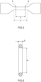
Fig. 5 ] A schematic view illustrating a shape of a test specimen fabricated when measuring mechanical strength using test pieces A obtained in Examples and Comparative Examples. - [
Fig. 6 ] A schematic view illustrating a cross section of a test specimen fabricated when measuring compression set using test pieces B obtained in Examples and Comparative Examples. - Hereinafter, the sealing apparatus according to an embodiment of the present invention will be described with referring to the drawings. Incidentally, the room temperature described below shall be within a range of 23°C ± 2°C.
- The sealing apparatus according to the present embodiment is a sealing apparatus arranged between two members facing each other for sealing a space between the two members, and comprises a sealing body in contact with the space. The sealing apparatus according to the present embodiment is preferably used in a hydrogen energy system, in which the sealing body is in contact with hydrogen gas or liquid hydrogen, and the sealing apparatus is used as a hydrogen gas seal or liquid hydrogen seal.
-
Fig. 1 shows an example of an embodiment of the sealing apparatus comprising such a sealing body. Asealing apparatus 1 shown inFig. 1 is mounted in a mounting groove 4 (mounting portion) arranged in onemember 2 of twomembers other member 3, thereby sealing between the twomembers sealing apparatus 1 has a sealing ring 11 (ring packing made of rubber) made of rubbery elastic body, a first backup ring 21 (backup ring) arranged on a low-pressure side L of thesealing ring 11, and asecond backup ring 31 arranged between the sealingring 11 and thefirst backup ring 21. The twomembers piping member 2, a seal housing portion of theother piping member 3 is arranged, and thesealing apparatus 1 is mounted in theannular mounting groove 4 arranged on the outer peripheral side of the seal housing portion of thepiping member 2, and is in close contact with an inner peripheral surface of the seal housing portion of theother piping member 3. Sealed fluid is high-pressure hydrogen gas which attempts to flow from a high-pressure side H to the low-pressure side L. - The
first backup ring 21 for use is a backup ring made of nylon (product name). Nylon is one of resin materials, which is difficult for gas to pass through. Thesecond backup ring 31 for use is a backup ring made of a material that is softer than thefirst backup ring 21, such as a PTFE resin. For bothbackup rings - The sealing
ring 11 corresponds to a sealing body of the sealing apparatus according to the present invention. The sealingring 11 is annularly formed, and is held by the first andsecond backup rings ring 11 is the same as the material that forms the sealing body, which will be described later, and thesealing ring 11 exhibits the characteristics of the sealing body, which will be described later. - The
mounting groove 4 is basically formed as a space with a rectangular cross section, but a high-pressureside mounting part 4a for mounting thesealing ring 11 at the bottom of the groove, is formed as a flat surface forming a cylindrical surface. Also a low-pressureside mounting part 4b for mounting the first andsecond backup rings side mounting part 4a, is formed as an inclined surface forming a conical surface so that a gap (gap in the radial direction) between the twomembers mounting groove 4 gradually becomes shallower, and is formed as aninclined bottom surface 4c. - Also the first and
second backup rings side mounting part 4b are each basically formed in a rectangular cross sectional shape, but its inner peripheral surface, corresponding to theinclined bottom surface 4c, is formed as an inclined surface forming a conical surface so that the inner diameter dimension gradually increases from the high pressure side H to the low pressure side L, and is formed asinclined surfaces - In the
sealing apparatus 1 having such a configuration, when pressure P acts from the right-hand side ofFig. 1 , thesealing ring 11 is pressed against thesecond backup ring 31 on the low pressure side, but thissecond backup ring 31 is made of a PTFE resin, which is softer than thefirst backup ring 21 made of nylon. Therefore, it is designed to be possible to inhibit the sealingring 11 from being repeatedly pressed against the hard material and being damaged upon generation of alternating pressure or the like. Also thesecond backup ring 31 that is made of a PTFE resin, which is a soft material, is prone to projection, but thefirst backup ring 21 that is made of nylon, which is a hard material, prevents projection. - The mounting
groove 4 is also arranged with theinclined bottom surface 4c that gradually narrows a gap between the twomembers inclined surfaces inclined bottom surface 4c on their inner peripheral surfaces. Therefore, when a sealed fluid pressure acts on both backup rings 21 and 31 via the sealingring 11, both backup rings 21 and 31 are compressed in a manner to be forced into a narrow space and come into strong, intimate contact with the mating surfaces. As a result, there occurs a phenomenon whereby both backup rings 21 and 31 are compressed due to theinclined surfaces ring 11 is further less likely to project, but also that when the sealingring 11 alone cannot seal high-pressure hydrogen gas that is sealed fluid, the backup rings 21 and 31 can seal it. - The
backup ring 21 is also formed of nylon, which is difficult for gas to permeate. Therefore, from this point of view as well, it can be expected that leakage whereby high-pressure hydrogen gas that is sealed fluid permeates thebackup ring 21, will be effectively reduced. Furthermore, since a width dimension in the radial direction of thebackup ring 21 is smaller than a width dimension in the radial direction of thesecond backup ring 31, the permeation area is set small. Therefore, from this point of view as well, it is possible to effectively seal the high-pressure hydrogen gas, which is sealed fluid. - The sealing
apparatus 1 according to the present embodiment may also be used not only for a cylindrical gap between the two members, but also for a flat gap, i.e., a gap between end faces.Fig. 2 shows an example of the embodiment of such a sealing apparatus. In alower sealing apparatus 1A inFig. 2 , thefirst backup ring 21 orsecond backup ring 31 is aligned in the axial direction in order to seal a cylindrical gap between one pipingmember 2 and the other pipingmember 3, while in anupper sealing apparatus 1B inFig. 2 , thefirst backup ring 21 orsecond backup ring 31 is aligned in the radial direction in order to seal a flat gap between one pipingmember 2 and the other pipingmember 3. Arranging them in such a double manner further enables reducing leakage to the outside. -
Fig. 3 shows an example of the sealing apparatus according to another embodiment of the present invention. A sealingapparatus 100 shown inFig. 3 is a sealing member for a separator that is stacked on both sides of an electrolyte membrane/electrode assembly (hereinafter referred to as MEA) in a general fuel cell, i.e., a cell seal for a fuel cell. Such a cell seal for a fuel cell is arranged between a separator and an MEA, which are two members facing each other to tightly seal a space between the separator and MEA (not shown). A separator of a fuel cell needs to supply fluid for a fuel cell (fuel gas containing hydrogen, oxidant gas containing oxygen, and the like) to MEA without leakage to the outside, and an endless gasket serves to seal such fluid for a fuel cell within a space surrounded by the gasket. - In the
sealing apparatus 100 shown inFig. 3 , anendless gasket 102 that is made of elastic material and extends along a surface of asubstrate 101, is formed around aventilation hole 101a on a surface of the plate-like substrate 101.Fig. 4 shows a schematic cross section of thesealing apparatus 100 along a line AA' inFig. 3 , in which agasket 102 is formed with four projecting portions that project from the surface of thesubstrate 101. As shown inFig. 4 , thegasket 102 has abase portion 102a bonded to the surface of thesubstrate 101 and aseal lip portion 102b projecting in a mountain shape from thebase portion 102a. Note that, on the line AA' inFig. 3 , there is a location (not shown) through which a molding material of thegasket 102 flows in and out upon molding of thegasket 102. - The
substrate 101 which is, for example, a thin plate including a metal plate such as stainless steel, a carbon plate or the like is used. Thesubstrate 101 and thegasket 102 are bonded via an adhesive layer or by an adhesive contained in thegasket 102. Also thesealing apparatus 100 may be an integrally molded cell seal in which a surface of the plate-like substrate 101 is integrally molded with theendless gasket 102 made of elastic material and extending along the surface of thesubstrate 101. Thesubstrate 101 of such an integrally molded cell seal is a member included in a cell structure of a fuel cell that is integrally molded with thegasket 102, and examples of thesubstrate 101 include a separator, MEA, a gas diffusion layer (GDL), and the like. - The
gasket 102 corresponds to the sealing body of the sealing apparatus according to the present invention. As shown inFig. 4 , the cross-sectional shape of thegasket 102 is a projecting shape. A material of thegasket 102 is the same as the material that forms the sealing body, which will be described later, and thegasket 102 exhibits the characteristics of the sealing body, which will be described later. - The sealing body of the sealing apparatus according to the present embodiment is a vulcanized molded product of a rubber composition containing (A) a natural rubber component selected from natural rubber and epoxy-modified natural rubber having an epoxidation degree of 1% or more and less than 50%, (B) a filler selected from carbon black and silica, (C) an organic peroxide-based crosslinking agent, and optionally (D) a silane coupling agent, provided that when the filler is carbon black, the rubber composition contains epoxy-modified natural rubber having an epoxidation degree of 1% or more and less than 50%, and when the filler is silica, the rubber composition further contains a silane coupling agent. Natural rubber is believed to undergo an oxidative decomposition reaction starting from a diene structure (C=C bond) under a high-temperature air atmosphere. Therefore, in a rubber composition containing a natural rubber component filled with carbon black, use of appropriately epoxidized natural rubber inhibits compression set and enables improving resistance to compression set in high-temperature air. Further adding a silane coupling agent to a rubber composition containing a natural rubber component filled with silica enables improving the resistance to compression set in high-temperature air while maintaining excellent cold resistance, even though the natural rubber is not epoxidized.
- In such a manner, even though natural rubber is used as a main raw material, using the specific rubber composition described above upon fabrication of sealing body makes it possible to obtain a sealing body that is less likely to crack even under high pressures, has high elastic recovery even in low temperature ranges, and has small compression set at high temperature ranges, which are all characteristics required for a hydrogen sealing material, as a result of which it is possible to realize a sealing apparatus that exhibits high mechanical strength under high pressures, and further has excellent cold resistance at low temperature ranges and resistance to compression set at high temperature ranges.
- A shape of the sealing body is not particularly limited, and can be formed into any shape depending on its application. For example, it may be a sealing member in sheet form with a cross-sectional shape of a square, rectangle, disk, or the like., or an annular sealing member such as an O-ring or a square ring, and these annular portions may be formed in a portion of the sealing body.
- The natural rubber component for use is natural rubber that has not been chemically modified at all, or natural rubber that has been epoxy-modified with a diene portion having an epoxidation degree of 1% or more and less than 50%. Natural rubber is rubber refined from sap (latex) of natural trees, and is diene-based rubber that is different from synthetic rubber that was chemically synthesized using petroleum, naphtha, and the like as raw materials. A diene portion of the natural rubber can be epoxidized by a reaction between formic acid and hydrogen peroxide solution. The epoxy-modified natural rubber has an epoxidation degree of 1% or more and less than 50%, preferably has an epoxidation degree of 10% or more and 40% or less, and more preferably has an epoxidation degree of 20% or more and 30% or less.
- The natural rubber and the epoxy-modified natural rubber may be used singly or in combinations of two or more thereof. Using such natural rubber enables improving the mechanical properties of the sealing body. Also the natural rubber and epoxy-modified natural rubber may be commercially available products. Examples of the commercially available natural rubber and epoxy-modified natural rubber include natural rubber "RSS No. 1" (imported product of TOYOTSU CHEMIPLAS CORPORATION), natural rubber having an epoxidation degree of 25% "ENR25" (imported product of Sanyo Trading Co., Ltd.).
- The rubber composition is compounded with a filler. The filler contained in the rubber composition can improve the mechanical strength and compression set of the resulting vulcanizate. As the filler, carbon black and silica, which are common reinforcing materials, are used. The fillers may be used singly or in combinations of two or more thereof.
- Carbon black can be appropriately selected from known materials, for example, hard carbon such as Super Abrasion Furnace (SAF) carbon black, Intermediate Super Abrasion Furnace (ISAF) carbon black, High Abrasion Furnace (HAF) carbon black, and Easy Processing Channel (EPC) carbon black, as well as soft carbon such as eXtra Conductive Furnace (XCF) carbon black, Fast Extruding Furnace (FEF) carbon black, General Purpose Furnace (GPF) carbon black, High Modulus Furnace (HMF) carbon black, Semi-Reinforcing Furnace (SRF) carbon black, Fine Thermal (FT) carbon black, and Medium Thermal (MT) carbon black. Examples of commercially available carbon black include "Vulcan (registered trademark) 3L" (HAF carbon) manufactured by Cabot Corporation and the like. The content of carbon black is not particularly limited, but is preferably 1 part by mass or more and 100 parts by mass or less, and more preferably 25 parts by mass or more and 75 parts by mass or less, relative to 100 parts by mass of the natural rubber component. The carbon black may be used singly or in combinations of two or more thereof.
- Silica may be appropriately selected from any known material, but it preferably has favorable kneading workability. Examples of commonly used silica include dry-process silica produced by a thermal decomposition method of halogenated silicic acid or organic silicon compounds, or by a method for heating and reducing silica sand and oxidizing vaporized SiO with air, or the like, and wet-process silica produced by a thermal decomposition method of sodium silicate, or the like. Examples of commercially available silica products include, for example, "Ultrasil (registered trademark) 360" manufactured by Evonik Japan Co., Ltd., and the like. The content of silica is not particularly limited, but is preferably 1 part by mass or more and 100 parts by mass or less, and more preferably 25 parts by mass or more and 75 parts by mass or less, relative to 100 parts by mass of the natural rubber component. The silica may be used singly or in combinations of two or more thereof.
- The organic peroxide-based crosslinking agent is used as a crosslinking agent that forms a peroxide crosslink of the natural rubber component. By using the organic peroxide-based crosslinking agent as the crosslinking agent, excellent resistance to compression set is imparted to the sealing body. Examples of the organic peroxide-based crosslinking agents include, for example, dicumyl peroxide, cumene hydroperoxide, p-methane hydroperoxide, 2,5-dimethylhexane-2,5-dihydroperoxide, di-tert-butyl peroxide, benzoyl peroxide, m-toluyl peroxide, 2,5-dimethyl-2,5-bis(tert-butylperoxy)hexane, 2,5-dimethyl-2,5-bis(tert-butylperoxy)-3-hexyne, 1,3-bis(tert-butylperoxyisopropyl)benzene, 2,5-dimethyl-2,5-di(benzoylperoxy)hexane, 1,1,3,3-tetramethylbutylperoxy-2-ethylhexanoate, tert-butylperoxybenzoate, tert-butylperoxylaurate, di(tert-butylperoxy)adipate, di(2-ethoxyethylperoxy)dicarbonate, bis(4-tert-butylcyclohexyl)peroxydicarbonate, and the like. Among these, dicumyl peroxide is preferred.
- As a commercially available organic peroxide-based crosslinking agent, for example, "Percumyl (registered trademark) D" manufactured by NOF CORPORATION and the like can be used. The content of the organic peroxide-based crosslinking agent is preferably 0.1 parts by mass or more and 10 parts by mass or less, and more preferably 1 part by mass or more and 5 parts by mass or less, relative to 100 parts by mass of the natural rubber component. The organic peroxide-based crosslinking agent may be used singly or in combinations of two or more thereof.
- When the rubber composition contains silica as a filler, a silane coupling agent is further compounded into the rubber composition. As the silane coupling agent, preferred is a silane coupling agent having a mercapto group, for example, 3-mercaptopropyltrimethoxysilane, 3-mercaptopropyltriethoxysilane, 3-mercaptopropyldiethoxymethoxysilane, 3-mercaptopropyltripropoxysilane, 3-mercaptopropyldipropoxymethoxysilane, 3-mercaptopropyltributoxysilane, 3-mercaptopropyldibutoxymethoxysilane, 3-mercaptopropylmethyldimethoxysilane, 3-mercaptopropyldimethylmethoxysilane, 3-mercaptopropylmethyldiethoxysilane, 3-mercaptopropyldimethylethoxysilane, 3-mercaptopropylmethyldipropoxysilane, 3-mercaptopropylpropoxydimethylsilane, 3-mercaptopropylmethyldiisopropoxysilane, 3-mercaptopropylisopropoxydimethylsilane, 3-mercaptopropylmethyldibutoxysilane, 3-mercaptopropyldimethylbutoxysilane, 2-mercaptoethyltrimethoxysilane, 2-mercaptoethyltriethoxysilane, mercaptomethyltrimethoxysilane, mercaptomethyltriethoxysilane, and the like.
- As a commercially available silane coupling agent, for example, "KBM-803" manufactured by Shin-Etsu Chemical Co., Ltd. and the like can be used. The content of the silane coupling agent is preferably 0.1 parts by mass or more and 10 parts by mass or less and more preferably 1 part by mass or more and 5 parts by mass or less, relative to 100 parts by mass of the natural rubber component. The silane coupling agent may be used singly or in combinations of two or more thereof.
- The rubber composition may contain other compounding components in addition to the above-described components, if necessary. Examples of the other compounding components include various additives such as a crosslinking accelerator, a plasticizer, an anti-aging agent, an auxiliary agent, a slip agent, an adhesive, lubricant, a flame retardant, a fungicide, and an antistatic agent. These additives may be used singly or in combinations of two or more thereof. Also, the compounding amount of these additives is not particularly limited as long as it does not impede the purpose and effect of the present invention, and an appropriate amount according to the compounding purpose can be compounded.
- The method for producing the sealing body is not particularly limited, and may be a method that includes, for example, appropriately compounding the above-described natural rubber component, filler, and organic peroxide-based crosslinking agent, as well as a silane coupling agent and various optional additives, which are compounded, if necessary, in a predetermined ratio, and then kneading them by using a kneading machine such as a single-screw extruder, a twin-screw extruder, a roll, a Banbury mixer, a kneader, or a high-shear mixer to produce a rubber composition. Note that, before kneading, mastication, pre-kneading, or the like may be performed if necessary.
- Furthermore, the obtained rubber composition undergoes vulcanization molding to be able to produce a vulcanized molded product having a shape of the sealing body. The vulcanization molding of the rubber composition is generally performed by pressurized vulcanization at about 150 to 230°C for approximately 0.5 to 30 minutes using an injection molding machine, a compression molding machine, or the like. After undergoing such primary vulcanization (pressurized vulcanization), the rubber composition may also undergo secondary vulcanization, if necessary, in order to ensure that an inside of the vulcanized molded product is also vulcanized. The secondary vulcanization can generally be carried out by heating the rubber composition in an oven, or by steam heating, hot air heating, or the like at about 150 to 250°C for approximately 0.5 to 24 hours.
- The sealing body of the sealing apparatus according to the present embodiment has a tensile strength (tensile strength measured under the conditions of test specimen shape: dumbbell-shaped No. 6, rate: 500 mm/min, distance between marked lines: 20 ± 0.5 mm, atmosphere: air, test temperature: room temperature), measured in accordance with the provisions of JIS K6251:2017 (the Japanese Industrial Standards created by modifying the technical content based on ISO37 (5th edition, 2011)), of 10 MPa or more and preferably 15 MPa or more. Also the sealing body has an elongation at break (elongation at break measured under the conditions of test specimen shape: dumbbell-shaped No. 6, rate: 500 mm/min, distance between marked lines: 20 ± 0.5 mm, atmosphere: air, test temperature: room temperature), measured in accordance with the provisions of JIS K6251:2017, of 200% or more and preferably 300% or more. The sealing body having a tensile strength of 10 MPa or more and an elongation at break of 200% or more can provide a sealing apparatus comprising a sealing body that exhibits high mechanical strength even under high pressures.
- The sealing body of the sealing apparatus according to the present embodiment has a TR10 temperature in a low-temperature elastic recovery test (TR test) (TR10 temperature measured in the low-temperature elastic recovery test (TR test) under the conditions of test specimen shape: I-shaped as described in the provisions of JIS K6261-4: 2017, heat medium: ethanol, test temperature: - 70°C to 23°C), measured in accordance with the provisions of JIS K6261-4: 2017 (the Japanese Industrial Standards created by modifying the technical content based on ISO2921 (5th edition, 2011)), of -40°C or lower and preferably -60°C or lower. The temperature at TR10 is -40°C or lower, enables providing a sealing apparatus comprising a sealing body that has excellent cold resistance in low temperature ranges.
- The sealing body of the sealing apparatus according to the present embodiment has a compression set at 100°C with an elapsed time of 70 hours in a shape of G25 O-ring described in the provisions of JIS B 2401-1: 2012 (Japanese Industrial Standards created by modifying the technical content based on ISO3601-1 (4th edition, 2008)) (compression set measured under the conditions of compression plate: smooth stainless steel plate, test specimen shape: G25 O-ring as described in the provisions of JIS B 2401-1: 2012, spacer thickness: 2.30 mm, compression rate: 25%, atmosphere: air, test temperature: 100°C, exposure time: 70 hours, conditions when left stand after release: room temperature for 30 minutes), measured in accordance with the provisions of JIS K 6262:2013 (the Japanese Industrial Standards created by modifying the technical content based on ISO815-1 and ISO815-2 (both 1st editions, 2008)), of 40% or less and preferably 35% or less. The compression set under such conditions of 40% or less enables providing a sealing apparatus comprising a sealing body that has excellent resistance to compression set at high temperature ranges.
- Based on the above-described embodiments, the present invention relates to the following [1] to [7].
- [1] A sealing apparatus arranged between two members facing each other for sealing a space between the two members,
- characterized in that the sealing apparatus comprises a sealing body in contact with the space,
- and in that the sealing body has a tensile strength of 10 MPa or more measured in accordance with the provisions of JIS K 6251: 2017, an elongation at break of 200% or more measured in accordance with the provisions of JIS K 6251: 2017, a TR10 temperature of -40°C or lower, measured in accordance with the provisions of JIS K 6261-4:2017 in a low-temperature elastic recovery test, and a compression set at 100°C with an elapsed time of 70 hours in a shape of a G25 O-ring as described in the provisions of JIS B 2401-1: 2012, measured in accordance with the provisions of JIS K 6262: 2013, of 40% or less.
- [2] The sealing apparatus according to [1] above, wherein the sealing body is annular.
- [3] The sealing apparatus according to [1] or [2] above, wherein the sealing body is held by a backup ring.
- [4] The sealing apparatus according to [1] above, wherein a cross-sectional shape of the sealing body is a projecting shape.
- [5] The sealing apparatus according to [4] above, wherein the sealing body is arranged on a plate-like substrate, and the substrate is a plate made of metal or carbon.
- [6] The sealing apparatus according to [5] above, wherein the substrate and the sealing body are bonded by an adhesive comprised in the sealing body.
- [7] The sealing apparatus according to any one of [1] to [6] above, wherein the sealing body is in contact with hydrogen gas.
- [8] The sealing apparatus according to any one of [1] to [6] above, wherein the sealing body is in contact with liquid hydrogen.
- [9] The sealing apparatus according to any one of [1] to [8] above, wherein the sealing apparatus is for use in a hydrogen energy system.
- [10] A sealing apparatus arranged between two members facing each other for sealing a space between the two members,
- characterized in that the sealing apparatus comprises a sealing body in contact with the space,
- and in that the sealing body is a vulcanized molded product of a rubber composition comprising (A) a natural rubber component selected from natural rubber and epoxy-modified natural rubber having an epoxidation degree of 1% or more and less than 50%, (B) a filler selected from carbon black and silica, (C) an organic peroxide-based crosslinking agent, and optionally (D) a silane coupling agent, provided that when the filler is carbon black, the rubber composition comprises epoxy-modified natural rubber having an epoxidation degree of 1% or more and less than 50%, and when the filler is silica, the rubber composition further comprises a silane coupling agent.
- [11] The sealing apparatus according to [10] above, wherein the rubber composition further comprises (E) at least one additive selected from the group consisting of a crosslinking accelerator, an auxiliary, and an anti-aging agent.
- Thus, the embodiments of the present invention were described above, but the present invention is not limited to the above embodiments, includes all aspects included in the concept of the present invention and the scope of the claims, and can be modified in various ways within the scope of the present invention.
- Next, Examples of the present invention will be described, but the present invention is not limited to these Examples.
- 100 parts by mass of natural rubber having an epoxidation degree of 25% ("ENR25", imported product of Sanyo Trading Co., Ltd.) was fed in a kneading extrusion apparatus ("Labo Plastomill 30C150", manufactured by TOYO SEIKI CO., LTD.) and masticated at 50°C for 15 minutes. Thereafter, 50 parts by mass of a filler A (carbon black: product name "Vulcan (registered trademark) 3L", manufactured by Cabot Japan K. K.), 2.5 parts by mass of a crosslinking agent A (dicumyl peroxide: product name "Percumyl (registered trademark) D", manufactured by NOF CORPORATION), 5 parts by mass of an auxiliary agent A (zinc oxide: product name "Zinc Oxide", manufactured by Seido Chemical Industry Co., Ltd.), 1 part by mass of an auxiliary agent B (stearic acid: product name "DTST", manufactured by Miyoshi Oil & Fat Co., Ltd.), and further 2 parts by mass of an anti-aging agent (2,2,4-trimethyl-1,2-dihydroquinoline polymer: product name "Nocrac 224", manufactured by OUCHI SHINKO CHEMICAL INDUSTRY CO., LTD.) were fed and the mixture was kneaded at 50°C for 15 minutes to fabricate a rubber dough. Next, the obtained rubber dough was fed into a roll kneader ("LABORTORY MILL", manufactured by Kansai Roll Co., Ltd.), and passed therethrough with a roll gap of 1.5 to 2.5 mm five times followed by being passed therethrough with a roll gap of 1 mm ten times to fabricate a rubber composition.
- The rubber composition obtained was crosslinked by hot press at 170°C using a press machine ("80 TON PRESS", manufactured by Hokutan Kikai Kogyo Kabushiki Kaisha), and was crosslinked for a time 1.5 times a t90 (90% crosslinked time) to undergo pressurized vulcanization (primary vulcanization) and to fabricate a test piece A.
- The rubber composition obtained was crosslinked by hot press at 170°C using a press machine ("50 TON KV PRESS", manufactured by KODAISHOJI Co., LTD.), and was crosslinked for a time 1.5 times a t90 (90% crosslinked time) to undergo pressurized vulcanization (primary vulcanization) and to fabricate a test piece B.
- The tensile strength and elongation at break of the test piece A were measured using a tensile tester (Strograph (registered trademark) AE, manufactured by Toyo Seiki Seisaku-sho, Ltd.) under the following test conditions in accordance with the provisions of JIS K 6251: 2017. The results are shown in Table 1.
-
- · Test specimen shape: Dumbbell No. 6
(the test specimen is dumbbell-shaped as shown inFig. 5 , where S is a marked line, D is an initial distance between the marked lines, and T is a parallel portion. For the dumbbell No. 6, D = 20 ± 0.5 mm, and a thickness of T = 2.0 ± 0.2 mm.) - · Rate: 500 mm/min
- · Atmosphere: Air
- · Test temperature: Room temperature
- The test piece A underwent a low-temperature elastic recovery test (TR test) under the following test conditions in accordance with the provisions of JIS K6261-4: 2017 using a TR tester "No. 145-L", manufactured by YASUDA SEIKI SEISAKUSHO, LTD.), and a temperature at TR10 was measured. The results are shown in Table 1.
-
- · Test specimen shape: I-shape as described in the provisions of JIS K6261-4: 2017 · Heat medium: Ethanol
- · Test temperature: -70°C to 23°C
- For the test piece B, a compression set was measured under the following test conditions in accordance with the provisions of JIS K 6262: 2013. The results are shown in Table 1.
-
- · Compression plate: Smooth stainless steel plate
- · Specimen shape: G25 O-ring as described in the provisions of JIS B 2401-1: 2012 (
Fig. 6 is a schematic view illustrating the cross section of the O-ring used in the test specimen, where di is an inner diameter and d2 is a thickness. For the G25 O-ring, di = 24.4 ± 0.25 mm, d2 = 3.1 ± 0.10 mm.) - · Spacer thickness: 2.30 mm
- · Compression rate: 25%
- · Atmosphere: Air
- · Test temperature: 100°C
- · Exposure time: 70 hours
- · Conditions when left stand after release: 30 minutes at room temperature
- A rubber composition and respective test pieces A and B were fabricated in the same manner as in Example 1, except that natural rubber ("RSS No. 1", imported product of TOYOTSU CHEMIPLAS CORPORATION) was used instead of natural rubber having an epoxidation degree of 25%, a filler B (silica: trade name "Ultrasil (registered trademark) 360", manufactured by Evonik Japan Co., Ltd.) was used instead of the filler A, and 1 part by mass of a silane coupling agent (mercapto group-containing silane coupling agent: trade name "KBM-803", manufactured by Shin-Etsu Chemical Co., Ltd.) was further compounded, and then the above measurements were made. The results are shown in Table 1.
- A rubber composition and respective test pieces A and B were fabricated in the same manner as in Example 1, except that natural rubber ("RSS No. 1", imported product of TOYOTSU CHEMIPLAS CORPORATION) instead of natural rubber having an epoxidation degree of 25% and 0.5 parts by mass of a crosslinking agent B (sulfur: trade name "Colloidal Sulfur A", manufactured by Tsurumi Chemical Industry Co., Ltd.) instead of the crosslinking agent A, were used, 1.5 parts by mass of a crosslinking accelerator A (N-cyclohexyl-2-benzothiazole sulfenamide: trade name "Noccela (registered trademark) CZ-G", manufactured by OUCHI SHINKO CHEMICAL CO., LTD.) and 1 part by mass of a crosslinking accelerator B (tetramethylthiuram disulfide: trade name "Noccela (registered trademark) TT-P", manufactured by OUCHI SHINKO CHEMICAL CO., LTD.) were further compounded, and when fabricating respective test pieces A and B, the crosslinking temperature was changed from 170°C to 150°C, and then the above measurements were made. The results are shown in Table 1.
- A rubber composition and respective test pieces A and B were fabricated in the same manner as in Example 1, except that natural rubber ("RSS No. 1", imported product of TOYOTSU CHEMIPLAS CORPORATION) was used instead of natural rubber having an epoxidation degree of 25%, and then the above measurements were made. The results are shown in Table 1.
- A rubber composition and respective test pieces A and B were fabricated in the same manner as in Example 1, except that natural rubber ("ENR50", imported product of Sanyo Trading Co., Ltd.) having an epoxidation degree of 50% was used instead of natural rubber having an epoxidation degree of 25%, and then the above measurements were made. The results are shown in Table 1.
- A rubber composition and respective test pieces A and B were fabricated in the same manner as in Example 2, except that no silane coupling agent was compounded, and then the above measurements were made. The results are shown in Table 1.
[Table 1] Example 1 Example 2 Comparative Example 1 Comparative Example 2 Comparative Example 3 Com parative Example 4 Rubber composition Natural rubber 100 100 100 100 Natural rubber having a degree of epoxidation of 25% 100 Natural rubber having a degree of epoxidation of 50% 100 Filler A 50 50 50 50 Filler B 50 50 Crosslinking agent A 2.5 2.5 2.5 2.5 2.5 Crosslinking agent B 0.5 Silane coupling agent 1 Crosslinking accelerator A 1.5 Crosslinking accelerator B 1 Auxiliary agent A 5 5 5 5 5 5 Auxiliary agent B 1 1 1 1 1 1 Anti-aging agent 2 2 2 2 2 2 Mechanical strength Tensile strength [MPa] 23.8 15.8 26.9 23.9 24.4 18.7 Elongation at break [%] 309 389 504 300 314 453 Resistance to compression set Compression set [%] 40 35 78 49 33 64 Cold resistance TR10 [°C] -41 -61 -60 -60 -19 -61 - Each component shown in Table 1 above is as follows. Incidentally, the values for each component in Table 1 above represent "parts by mass".
- · Natural rubber: Product name "RSS No. 1", imported product of TOYOTSU CHEMIPLAS CORPORATION
- · Natural rubber having an epoxidation degree of 25% ("ENR25", imported product of Sanyo Trading Co., Ltd.)
- · Natural rubber having an epoxidation degree of 50% ("ENR50", imported product of Sanyo Trading Co., Ltd.)
- · Filler A: Carbon black (product name "Vulcan (registered trademark) 3L", manufactured by Cabot Japan K. K.)
- · Filler B: Silica (product name "Ultrasil (registered trademark) 360", manufactured by Evonik Japan Co., Ltd.)
- · Crosslinking agent A: Dicumyl peroxide (product name "Percumyl (registered trademark) D", manufactured by NOF Corporation)
- · Crosslinking agent B: Sulfur (product name: "Colloidal Sulfur A", manufactured by Tsurumi Chemical Industry Co., Ltd.)
- · Silane coupling agent: Mercapto group-containing silane coupling agent (product name: "KBM-803", manufactured by Shin-Etsu Chemical Co., Ltd.)
- · Auxiliary agent A: Zinc oxide (product name "Zinc Oxide", manufactured by Seido Chemical Industry Co., Ltd.)
- · Auxiliary agent B: Stearic acid (product name: "DTST", manufactured by Miyoshi Oil & Fat Co., Ltd.)
- · Anti-aging agent: 2,2,4-Trimethyl-1,2-dihydroquinoline polymer (product name: "Nocrac 224", manufactured by OUCHI SHINKO CHEMICAL CO., LTD.)
- As can be found in Table 1, Examples 1 and 2 each exhibited the tensile strength of 10 MPa or more, the elongation at break of 200% or more, and the high mechanical strength even under high pressures. Also Examples 1 and 2 exhibited the temperature of TR10 in the low-temperature elastic recovery test of -40°C or lower, and further the compression set at 100°C with an elapsed time of 70 hours, of 40% or less, resulting in being excellent in the cold resistance in low temperature ranges and the resistance to compression set in high temperature ranges.
- On the other hand, Comparative Example 1 in which the sulfur crosslinking agent was used as the crosslinking agent, exhibited the compression set of higher than 40%, indicating the poor resistance to compression set. Similarly, Comparative Example 2, in which carbon black was used as the filler and unmodified natural rubber was used as the natural rubber component, exhibited the compression set of higher than 40% and the poor resistance to compression set. On the other hand, Comparative Example 3, in which carbon black was used as the filler and natural rubber having an epoxidation degree of 50% was used as the natural rubber component, exhibited the compression set of 40% or less, but the TR10 temperature in the low-temperature elastic recovery test of higher than -40°C, indicating the poor cold resistance. Furthermore, Comparative Example 4, in which silica was used as the filler but no silane coupling agent was used, exhibited the compression set of higher than 40%, indicating the poor resistance to compression set.
-
- 1, 1A, 1B sealing apparatus,
- 2 one member (piping member),
- 3 the other member (piping member),
- 4 mounting groove,
- 4a high-pressure side mounting part,
- 4b low-pressure side mounting part,
- 4c inclined bottom surface,
- 11 sealing ring,
- 21 first backup ring (backup ring),
- 21a, 31a inclined surfaces,
- 31 second backup ring,
- 100 sealing apparatus,
- 101 substrate,
- 101a ventilation hole,
- 102 gasket,
- 102a base portion,
- 102b seal lip portion
Claims (11)
- A sealing apparatus arranged between two members facing each other for sealing a space between the two members,characterized in that the sealing apparatus comprises a sealing body in contact with the space,and in that the sealing body has a tensile strength of 10 MPa or more measured in accordance with the provisions of JIS K 6251: 2017, an elongation at break of 200% or more measured in accordance with the provisions of JIS K 6251: 2017, a TR10 temperature of -40°C or lower, measured in accordance with the provisions of JIS K 6261-4: 2017 in a low-temperature elastic recovery test, and a compression set at 100°C with an elapsed time of 70 hours in a shape of a G25 O-ring as described in the provisions of JIS B 2401-1: 2012, measured in accordance with the provisions of JIS K 6262: 2013, of 40% or less.
- The sealing apparatus according to claim 1, wherein the sealing body is annular.
- The sealing apparatus according to claim 1 or 2, wherein the sealing body is held by a backup ring.
- The sealing apparatus according to claim 1, wherein a cross-sectional shape of the sealing body is a projecting shape.
- The sealing apparatus according to claim 4, wherein the sealing body is arranged on a plate-like substrate, and the substrate is a plate made of metal or carbon.
- The sealing apparatus according to claim 5, wherein the substrate and the sealing body are bonded by an adhesive comprised in the sealing body.
- The sealing apparatus according to claim 1 or 2, wherein the sealing body is in contact with hydrogen gas.
- The sealing apparatus according to claim 1 or 2, wherein the sealing body is in contact with liquid hydrogen.
- The sealing apparatus according to claim 1 or 2, wherein the sealing apparatus is for use in a hydrogen energy system.
- A sealing apparatus arranged between two members facing each other for sealing a space between the two members,characterized in that the sealing apparatus comprises a sealing body in contact with the space,and in that the sealing body is a vulcanized molded product of a rubber composition comprising (A) a natural rubber component selected from natural rubber and epoxy-modified natural rubber having an epoxidation degree of 1% or more and less than 50%, (B) a filler selected from carbon black and silica, (C) an organic peroxide-based crosslinking agent, and optionally (D) a silane coupling agent, provided that when the filler is carbon black, the rubber composition comprises epoxy-modified natural rubber having an epoxidation degree of 1% or more and less than 50%, and when the filler is silica, the rubber composition further comprises a silane coupling agent.
- The sealing apparatus according to claim 10, wherein the rubber composition further comprises (E) at least one additive selected from the group consisting of a crosslinking accelerator, an auxiliary agent, and an anti-aging agent.
Applications Claiming Priority (2)
| Application Number | Priority Date | Filing Date | Title |
|---|---|---|---|
| JP2022060434 | 2022-03-31 | ||
| PCT/JP2023/013081 WO2023190825A1 (en) | 2022-03-31 | 2023-03-30 | Sealing device |
Publications (2)
| Publication Number | Publication Date |
|---|---|
| EP4502033A1 true EP4502033A1 (en) | 2025-02-05 |
| EP4502033A4 EP4502033A4 (en) | 2026-03-25 |
Family
ID=88202765
Family Applications (1)
| Application Number | Title | Priority Date | Filing Date |
|---|---|---|---|
| EP23780833.2A Pending EP4502033A4 (en) | 2022-03-31 | 2023-03-30 | SEALING DEVICE |
Country Status (5)
| Country | Link |
|---|---|
| US (1) | US20250215200A1 (en) |
| EP (1) | EP4502033A4 (en) |
| JP (2) | JP7695471B2 (en) |
| CN (1) | CN118974450A (en) |
| WO (1) | WO2023190825A1 (en) |
Family Cites Families (10)
| Publication number | Priority date | Publication date | Assignee | Title |
|---|---|---|---|---|
| JPH09229196A (en) * | 1996-02-19 | 1997-09-02 | Nippon Reinz Co Ltd | Metal gasket |
| US6492454B1 (en) * | 1999-04-01 | 2002-12-10 | The Yokohama Rubber Co., Ltd. | Rubber composition containing rubber, mercapto-triazine and epoxy grafter polymer |
| JP4636281B2 (en) * | 2004-12-28 | 2011-02-23 | Nok株式会社 | Sealing device |
| JP2008057711A (en) | 2006-09-01 | 2008-03-13 | Toyota Motor Corp | High pressure hydrogen container |
| JP2010165577A (en) * | 2009-01-16 | 2010-07-29 | Nok Corp | Seal structure of fuel battery cell |
| JP2014114878A (en) * | 2012-12-10 | 2014-06-26 | Kawasaki Heavy Ind Ltd | Seal structure |
| JP6641801B2 (en) | 2014-10-30 | 2020-02-05 | 株式会社ジェイテクト | Seal material |
| JP6709641B2 (en) * | 2015-10-15 | 2020-06-17 | 三井化学株式会社 | Seal packing |
| JP6859153B2 (en) * | 2017-03-27 | 2021-04-14 | 三井化学株式会社 | Ethylene copolymer composition for packing and packing applications |
| JP6835770B2 (en) * | 2018-05-30 | 2021-02-24 | 三菱電線工業株式会社 | Crosslinked rubber composition and sealing material using it |
-
2023
- 2023-03-30 CN CN202380031439.8A patent/CN118974450A/en active Pending
- 2023-03-30 WO PCT/JP2023/013081 patent/WO2023190825A1/en not_active Ceased
- 2023-03-30 EP EP23780833.2A patent/EP4502033A4/en active Pending
- 2023-03-30 JP JP2024512769A patent/JP7695471B2/en active Active
- 2023-03-30 US US18/850,905 patent/US20250215200A1/en active Pending
-
2025
- 2025-03-27 JP JP2025053602A patent/JP2025092588A/en active Pending
Also Published As
| Publication number | Publication date |
|---|---|
| US20250215200A1 (en) | 2025-07-03 |
| EP4502033A4 (en) | 2026-03-25 |
| WO2023190825A1 (en) | 2023-10-05 |
| CN118974450A (en) | 2024-11-15 |
| JP2025092588A (en) | 2025-06-19 |
| JPWO2023190825A1 (en) | 2023-10-05 |
| JP7695471B2 (en) | 2025-06-18 |
Similar Documents
| Publication | Publication Date | Title |
|---|---|---|
| US7309068B2 (en) | Rubber gasket for separator of fuel cell | |
| US20150188154A1 (en) | Gasket for fuel cells | |
| CN104245816A (en) | Nbr composition | |
| EP2682426A1 (en) | Fluorine rubber composition | |
| EP2161301B1 (en) | EPDM rubber composition comprising Austin black | |
| JP2019199549A (en) | Rubber composition and seal material | |
| US20250215200A1 (en) | Sealing apparatus | |
| KR101664740B1 (en) | Gasket for fuel cells | |
| US9466844B2 (en) | Blended rubber gasket for fuel cells | |
| EP1928951B1 (en) | Rubber mixture for inner liner of pneumatic vehicle tyres | |
| KR101128404B1 (en) | method for manufacturing fuel cell gasket using the polyalkenamer rubber composition | |
| EP2864003B1 (en) | Adhesion promoting curative and stabilizer system for elastomer composition | |
| JP7742711B2 (en) | Sealing material for fuel cells | |
| KR101637849B1 (en) | Blend gasket for fuel cells | |
| JP2017122140A (en) | Rubber composition and rubber seal prepared therewith | |
| KR102445866B1 (en) | Nitrile rubber composition for O-rings with excellent elastic recovery properties | |
| KR101670689B1 (en) | Gasket rubber composition for braking system | |
| KR102100123B1 (en) | Fluorocarbon rubber composition having improved adhesion to metal when using bisphenol-based adhesive | |
| KR102408050B1 (en) | EPDM rubber gasket containing ion functional group with excellent durability under high pressure hydrogen gas and menufacturing method of gasket using the same | |
| KR100488878B1 (en) | Liquid-phase gasket composition having high performance and a gasket for fuel cell using the same | |
| KR102825710B1 (en) | Rubber-based elastic material for preventing pipe leakage with excellent tensile modulus and compressive strain and method for manufacturing the same | |
| JP2024109298A (en) | Rubber composition for sealing material and sealing material | |
| CN121699267A (en) | Hydrogenated nitrile for resisting carbon dioxide gas explosion and preparation method thereof | |
| KR20250061034A (en) | Seal rubber compositions for an electric automobile having excellent heat resistance and a seal molded article manufactured thereby | |
| KR100786369B1 (en) | Gasket Composition for Fuel Cell Stack |
Legal Events
| Date | Code | Title | Description |
|---|---|---|---|
| STAA | Information on the status of an ep patent application or granted ep patent |
Free format text: STATUS: THE INTERNATIONAL PUBLICATION HAS BEEN MADE |
|
| PUAI | Public reference made under article 153(3) epc to a published international application that has entered the european phase |
Free format text: ORIGINAL CODE: 0009012 |
|
| STAA | Information on the status of an ep patent application or granted ep patent |
Free format text: STATUS: REQUEST FOR EXAMINATION WAS MADE |
|
| 17P | Request for examination filed |
Effective date: 20241004 |
|
| AK | Designated contracting states |
Kind code of ref document: A1 Designated state(s): AL AT BE BG CH CY CZ DE DK EE ES FI FR GB GR HR HU IE IS IT LI LT LU LV MC ME MK MT NL NO PL PT RO RS SE SI SK SM TR |
|
| DAV | Request for validation of the european patent (deleted) | ||
| DAX | Request for extension of the european patent (deleted) | ||
| A4 | Supplementary search report drawn up and despatched |
Effective date: 20260223 |
|
| RIC1 | Information provided on ipc code assigned before grant |
Ipc: C08K 5/14 20060101AFI20260217BHEP Ipc: C08L 7/00 20060101ALI20260217BHEP Ipc: C08L 15/00 20060101ALI20260217BHEP Ipc: F16J 15/10 20060101ALI20260217BHEP Ipc: C08K 3/04 20060101ALI20260217BHEP Ipc: C08K 3/36 20060101ALI20260217BHEP Ipc: F16J 15/12 20060101ALI20260217BHEP Ipc: F16J 15/16 20060101ALI20260217BHEP |