EP4501867A1 - Membrane separation system and operation method for membrane separation system - Google Patents
Membrane separation system and operation method for membrane separation system Download PDFInfo
- Publication number
- EP4501867A1 EP4501867A1 EP23774493.3A EP23774493A EP4501867A1 EP 4501867 A1 EP4501867 A1 EP 4501867A1 EP 23774493 A EP23774493 A EP 23774493A EP 4501867 A1 EP4501867 A1 EP 4501867A1
- Authority
- EP
- European Patent Office
- Prior art keywords
- membrane
- permeated fluid
- separation
- membrane separation
- aqueous solution
- Prior art date
- Legal status (The legal status is an assumption and is not a legal conclusion. Google has not performed a legal analysis and makes no representation as to the accuracy of the status listed.)
- Withdrawn
Links
Images



Classifications
-
- B—PERFORMING OPERATIONS; TRANSPORTING
- B01—PHYSICAL OR CHEMICAL PROCESSES OR APPARATUS IN GENERAL
- B01D—SEPARATION
- B01D3/00—Distillation or related exchange processes in which liquids are contacted with gaseous media, e.g. stripping
- B01D3/14—Fractional distillation or use of a fractionation or rectification column
- B01D3/143—Fractional distillation or use of a fractionation or rectification column by two or more of a fractionation, separation or rectification step
- B01D3/145—One step being separation by permeation
-
- B—PERFORMING OPERATIONS; TRANSPORTING
- B01—PHYSICAL OR CHEMICAL PROCESSES OR APPARATUS IN GENERAL
- B01D—SEPARATION
- B01D3/00—Distillation or related exchange processes in which liquids are contacted with gaseous media, e.g. stripping
- B01D3/001—Processes specially adapted for distillation or rectification of fermented solutions
-
- B—PERFORMING OPERATIONS; TRANSPORTING
- B01—PHYSICAL OR CHEMICAL PROCESSES OR APPARATUS IN GENERAL
- B01D—SEPARATION
- B01D61/00—Processes of separation using semi-permeable membranes, e.g. dialysis, osmosis or ultrafiltration; Apparatus, accessories or auxiliary operations specially adapted therefor
- B01D61/36—Pervaporation; Membrane distillation; Liquid permeation
- B01D61/362—Pervaporation
- B01D61/3621—Pervaporation comprising multiple pervaporation steps
-
- C—CHEMISTRY; METALLURGY
- C12—BIOCHEMISTRY; BEER; SPIRITS; WINE; VINEGAR; MICROBIOLOGY; ENZYMOLOGY; MUTATION OR GENETIC ENGINEERING
- C12M—APPARATUS FOR ENZYMOLOGY OR MICROBIOLOGY; APPARATUS FOR CULTURING MICROORGANISMS FOR PRODUCING BIOMASS, FOR GROWING CELLS OR FOR OBTAINING FERMENTATION OR METABOLIC PRODUCTS, i.e. BIOREACTORS OR FERMENTERS
- C12M47/00—Means for after-treatment of the produced biomass or of the fermentation or metabolic products, e.g. storage of biomass
- C12M47/10—Separation or concentration of fermentation products
-
- C—CHEMISTRY; METALLURGY
- C12—BIOCHEMISTRY; BEER; SPIRITS; WINE; VINEGAR; MICROBIOLOGY; ENZYMOLOGY; MUTATION OR GENETIC ENGINEERING
- C12P—FERMENTATION OR ENZYME-USING PROCESSES TO SYNTHESISE A DESIRED CHEMICAL COMPOUND OR COMPOSITION OR TO SEPARATE OPTICAL ISOMERS FROM A RACEMIC MIXTURE
- C12P7/00—Preparation of oxygen-containing organic compounds
- C12P7/02—Preparation of oxygen-containing organic compounds containing a hydroxy group
- C12P7/04—Preparation of oxygen-containing organic compounds containing a hydroxy group acyclic
- C12P7/16—Butanols
-
- B—PERFORMING OPERATIONS; TRANSPORTING
- B01—PHYSICAL OR CHEMICAL PROCESSES OR APPARATUS IN GENERAL
- B01D—SEPARATION
- B01D2311/00—Details relating to membrane separation process operations and control
- B01D2311/25—Recirculation, recycling or bypass, e.g. recirculation of concentrate into the feed
- B01D2311/251—Recirculation of permeate
- B01D2311/2512—Recirculation of permeate to feed side
-
- B—PERFORMING OPERATIONS; TRANSPORTING
- B01—PHYSICAL OR CHEMICAL PROCESSES OR APPARATUS IN GENERAL
- B01D—SEPARATION
- B01D2311/00—Details relating to membrane separation process operations and control
- B01D2311/25—Recirculation, recycling or bypass, e.g. recirculation of concentrate into the feed
- B01D2311/252—Recirculation of concentrate
- B01D2311/2523—Recirculation of concentrate to feed side
-
- B—PERFORMING OPERATIONS; TRANSPORTING
- B01—PHYSICAL OR CHEMICAL PROCESSES OR APPARATUS IN GENERAL
- B01D—SEPARATION
- B01D2311/00—Details relating to membrane separation process operations and control
- B01D2311/26—Further operations combined with membrane separation processes
- B01D2311/2669—Distillation
-
- B—PERFORMING OPERATIONS; TRANSPORTING
- B01—PHYSICAL OR CHEMICAL PROCESSES OR APPARATUS IN GENERAL
- B01D—SEPARATION
- B01D2311/00—Details relating to membrane separation process operations and control
- B01D2311/26—Further operations combined with membrane separation processes
- B01D2311/2688—Biological processes
-
- B—PERFORMING OPERATIONS; TRANSPORTING
- B01—PHYSICAL OR CHEMICAL PROCESSES OR APPARATUS IN GENERAL
- B01D—SEPARATION
- B01D2313/00—Details relating to membrane modules or apparatus
- B01D2313/22—Cooling or heating elements
- B01D2313/221—Heat exchangers
-
- B—PERFORMING OPERATIONS; TRANSPORTING
- B01—PHYSICAL OR CHEMICAL PROCESSES OR APPARATUS IN GENERAL
- B01D—SEPARATION
- B01D2317/00—Membrane module arrangements within a plant or an apparatus
- B01D2317/02—Elements in series
- B01D2317/022—Reject series
-
- B—PERFORMING OPERATIONS; TRANSPORTING
- B01—PHYSICAL OR CHEMICAL PROCESSES OR APPARATUS IN GENERAL
- B01D—SEPARATION
- B01D2317/00—Membrane module arrangements within a plant or an apparatus
- B01D2317/02—Elements in series
- B01D2317/025—Permeate series
-
- C—CHEMISTRY; METALLURGY
- C02—TREATMENT OF WATER, WASTE WATER, SEWAGE, OR SLUDGE
- C02F—TREATMENT OF WATER, WASTE WATER, SEWAGE, OR SLUDGE
- C02F1/00—Treatment of water, waste water, or sewage
- C02F1/44—Treatment of water, waste water, or sewage by dialysis, osmosis or reverse osmosis
- C02F1/448—Treatment of water, waste water, or sewage by dialysis, osmosis or reverse osmosis by pervaporation
Definitions
- the present invention relates to a membrane separation system and a method for operating a membrane separation system.
- a volatile organic compound such as an alcohol
- a carbon source such as glucose
- Patent Literature 1 discloses a membrane separation system obtained by combining a membrane separation device with a fermenter.
- Patent Literature 1 JP 2010-161987 A
- the present invention provides a membrane separation system including:
- the present invention further provides a method for operating a membrane separation system including a first membrane separation device having a first separation membrane, a separation vessel, and a second membrane separation device having a second separation membrane, the method including:
- the present invention can provide a new membrane separation system suitable for efficiently separating a volatile organic compound from an aqueous solution containing the organic compound.
- a membrane separation system includes:
- the aqueous solution S2 is prepared by mixing the first permeated fluid with the second permeated fluid.
- the membrane separation system according to the first or second aspect further includes a tank for storing the aqueous solution S1 to be supplied to the first membrane separation device.
- the organic compound is a fermented product generated by a microorganism
- the tank is a fermenter for generating the organic compound.
- the first separation membrane allows a first non-permeated fluid to be generated from the aqueous solution S1, the first non-permeated fluid having a content of the organic compound lower than that in the aqueous solution S1
- the membrane separation system further includes a first non-permeated fluid discharge passage connected to the first membrane separation device and configured to discharge the first non-permeated fluid from the first membrane separation device, and the first non-permeated fluid discharge passage is connected to the tank.
- the second separation membrane allows a second non-permeated fluid to be generated from the aqueous phase, the second non-permeated fluid having a content of the organic compound lower than that in the aqueous phase, and the membrane separation system further includes a second non-permeated fluid discharge passage connected to the second membrane separation device and configured to discharge the second non-permeated fluid from the second membrane separation device.
- the membrane separation system according to the sixth aspect further includes an aqueous solution feed passage connected to the first membrane separation device and configured to supply the aqueous solution S1 to the first membrane separation device, wherein the second non-permeated fluid discharge passage is connected to the aqueous solution feed passage.
- the first membrane separation device has two membrane separation units and a connection passage connecting the two membrane separation units to each other, and the second non-permeated fluid discharge passage is connected to the connection passage.
- a content of the organic compound in the second non-permeated fluid is 2 wt% or less.
- the membrane separation system according to any one of the first to ninth aspects further includes a distillation device that distills the organic phase and generates a distillate having a content of the organic compound lower than that in the organic phase.
- the membrane separation system according to the tenth aspect further includes a distillate discharge passage connected to the distillation device and configured to discharge the distillate from the distillation device, wherein the distillate discharge passage is connected to at least one selected from the group consisting of the first permeated fluid feed passage and the separation vessel.
- At least one selected from the group consisting of the first separation membrane and the second separation membrane is a pervaporation membrane.
- the organic compound is at least one selected from the group consisting of an alcohol, ketone, and ester.
- a method for operating a membrane separation system is a method for operating a membrane separation system including a first membrane separation device having a first separation membrane, a separation vessel, and a second membrane separation device having a second separation membrane, the method including:
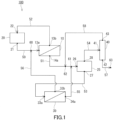
- a membrane separation system 100 of Embodiment 1 includes a first membrane separation device 10, a separation vessel 25, a second membrane separation device 30, a first permeated fluid feed passage 51, and a second permeated fluid feed passage 55.
- the first membrane separation device 10 has a first separation membrane, and further has, for example, a feed space and a permeation space separated from each other by the first separation membrane.
- the first membrane separation device 10 is a device that performs membrane separation for an aqueous solution S1 containing a volatile organic compound C by using the first separation membrane.
- the first separation membrane that the first membrane separation device 10 has can separate the aqueous solution S1 into a first permeated fluid and a first non-permeated fluid.
- the first separation membrane is a membrane that allows the organic compound C contained in the aqueous solution S1 to preferentially permeate therethrough. Accordingly, the first permeated fluid separated by the first separation membrane has a content of the organic compound C higher than that in the aqueous solution S1. In contrast, the first non-permeated fluid has a content of the organic compound C lower than that in the aqueous solution S1.
- the separation vessel 25 is a vessel for phase-separating an aqueous solution S2 containing the first permeated fluid.
- the aqueous solution S2 typically contains the later-described second permeated fluid in addition to the first permeated fluid.
- the aqueous solution S2 is a mixed solution containing the first permeated fluid that is a liquid and the second permeated fluid that is a liquid.
- the aqueous solution S2 contains the organic compound C at a content higher than that in the aqueous solution S1. In one example, when the aqueous solution S2 is left at rest in the separation vessel 25, the aqueous solution S2 is phase-separated into an aqueous phase and an organic phase.
- the aqueous phase has a content of water higher than that in the aqueous solution S2 and contains the organic compound C.
- the organic compound C may be saturated in the aqueous phase.
- the organic phase has a content of the organic compound C higher than that in the aqueous solution S2.
- the organic phase contains water in addition to the organic compound C and has a content of water lower than that in the aqueous solution S2.
- the second membrane separation device 30 has a second separation membrane, and further has, for example, a feed space and a permeation space separated from each other by the second separation membrane.
- the second membrane separation device 30 is a device that performs membrane separation for the above-mentioned aqueous phase by using the second separation membrane.
- the second separation membrane that the second membrane separation device 30 has can separate the aqueous phase into a second permeated fluid and a second non-permeated fluid.
- the second separation membrane is a membrane that allows the organic compound C contained in the aqueous phase to preferentially permeate therethrough. Accordingly, the second permeated fluid separated by the second separation membrane has a content of the organic compound C higher than that in the aqueous phase. In contrast, the second non-permeated fluid has a content of the organic compound C lower than that in the aqueous phase.
- the first permeated fluid feed passage 51 is a passage connected to a permeated fluid outlet (an outlet 14a) of the first membrane separation device 10 and a permeated fluid inlet (an inlet 26) of the separation vessel 25 and configured to deliver the first permeated fluid from the first membrane separation device 10 to the separation vessel 25.
- the first permeated fluid feed passage 51 may be provided with a decompression device and a heat exchanger (a chiller).
- the decompression device provided to the first permeated fluid feed passage 51 can decompress an inside of the permeation space of the first membrane separation device 10, for example.
- the decompression device is a vacuum device such as a vacuum pump.
- the vacuum pump is typically a gas transport vacuum pump, and a reciprocating vacuum pump and a rotary vacuum pump, etc. can be mentioned.
- Examples of the reciprocating vacuum pump include a diaphragm vacuum pump and a rocking piston vacuum pump.
- Examples of the rotary vacuum pump include: a liquid seal pump; an oil rotary pump (a rotary pump); a mechanical booster pump; and various kinds of dry pumps such as a roots dry pump, a claw dry pump, a screw dry pump, a turbo dry pump, and a scroll dry pump.
- the pump as the decompression device may include a variable speed mechanism for changing a rotational speed, etc.
- An example of the variable speed mechanism is an inverter that drives a motor of the pump. By controlling the rotational speed, etc. of the pump by the variable speed mechanism, it is possible to adjust properly a pressure in the permeation space of the first membrane separation device 10.
- the heat exchanger provided to the first permeated fluid feed passage 51 can cool the first permeated fluid, for example.
- the heat exchanger is, for example, a gas-liquid heat exchanger that causes heat exchange between a cooling medium, such as an antifreeze, and the first permeated fluid that is a gas.
- the heat exchanger makes it possible to cool and condense the first permeated fluid even in the case where the first permeated fluid is a gas. That is, the heat exchanger can change the state of the first permeated fluid from a gaseous state to a liquid state.
- the first permeated fluid feed passage 51 may be further provided with a heat exchanger for heating the condensed first permeated fluid that is a liquid.
- the second permeated fluid feed passage 55 is connected to a permeated fluid outlet (an outlet 34a) of the second membrane separation device 30 and at least one selected from the group consisting of the first permeated fluid feed passage 51 and the separation vessel 25.
- the second permeated fluid feed passage 55 is connected to the first permeated fluid feed passage 51 at a connecting point 61.
- the second permeated fluid feed passage 55 is a passage for supplying the second permeated fluid from the second membrane separation device 30 to the first permeated fluid feed passage 51 and/or the separation vessel 25.
- the second permeated fluid is supplied to the first permeated fluid feed passage 51 or the separation vessel 25 via the second permeated fluid feed passage 55. Thereby, the first permeated fluid is mixed with the second permeated fluid to prepare the aqueous solution S2.
- the membrane separation system 100 of the present embodiment in which the aqueous solution S2 containing the first permeated fluid and the second permeated fluid is processed in the separation vessel 25 is suitable for efficiently separating the organic compound C from the aqueous solution S1.
- the present invention provides a membrane separation system including:
- the second permeated fluid feed passage 55 may be provided with a decompression device and a heat exchanger (a chiller).
- the decompression device provided to the second permeated fluid feed passage 55 can decompress an inside of the permeation space of the second membrane separation device 30, for example.
- the heat exchanger provided to the second permeated fluid feed passage 55 can cool the second permeated fluid, for example.
- the heat exchanger is, for example, a gas-liquid heat exchanger that causes heat exchange between a cooling medium, such as an antifreeze, and the second permeated fluid that is a gas.
- the heat exchanger makes it possible to cool and condense the second permeated fluid even in the case where the second permeated fluid is a gas. That is, the heat exchanger can change the state of the second permeated fluid from a gaseous state to a liquid state.
- the second permeated fluid feed passage 55 may not be provided with the decompression device or the heat exchanger.
- the inside of the permeation space of the second membrane separation device 30 may be decompressed using the decompression device provided to the first permeated fluid feed passage 51. That is, one decompression device may be shared by the first membrane separation device 10 and the second membrane separation device 30.
- the decompression device is preferably located, on the first permeated fluid feed passage 51, between the connecting point 61 and the separation vessel 25.
- the second permeated fluid may be cooled by the heat exchanger provided to the first permeated fluid feed passage 51. That is, one heat exchanger may be shared for the first permeated fluid and the second permeated fluid.
- the aqueous solution S2 may be prepared by cooling a gas mixture containing the first permeated fluid that is a gas and the second permeated fluid that is a gas with the heat exchanger provided to the first permeated fluid feed passage 51.
- the heat exchanger is preferably located, on the first permeated fluid feed passage 51, between the connecting point 61 and the separation vessel 25.
- the organic compound C may be a fermented product generated by fermentation of a carbon source by a microorganism, or may be an alcohol (a bioalcohol, especially biobutanol), such as n-butanol, generated by a microorganism. That is, the aqueous solution S1 may be a fermented liquid containing the organic compound C as the fermented product.
- the present invention provides a membrane separation system including:
- the membrane separation system 100 further includes a tank 20.
- the tank 20 stores the aqueous solution S1 to be supplied to the first membrane separation device 10.
- the tank 20 is typically a fermenter for generating the organic compound C by fermentation of a carbon source by a microorganism.
- the membrane separation system 100 further includes an aqueous solution feed passage 50 and a first non-permeated fluid discharge passage 52.
- the aqueous solution feed passage 50 is a passage connected to an aqueous solution outlet (an outlet 21) of the tank 20 and an aqueous solution inlet (an inlet 13a) of the first membrane separation device 10 and configured to supply the aqueous solution S1 from the tank 20 to the first membrane separation device 10.
- the aqueous solution feed passage 50 may be provided with a pump that controls a flow rate of the aqueous solution S1.
- the first non-permeated fluid discharge passage 52 is a passage connected to a non-permeated fluid outlet (an outlet 13b) of the first membrane separation device 10 and configured to discharge the first non-permeated fluid from the first membrane separation device 10.
- the first non-permeated fluid discharge passage 52 may be connected to a non-permeated fluid inlet (an inlet 22) of the tank 20 and configured to deliver the first non-permeated fluid to the tank 20. That is, the membrane separation system 100 may be configured to allow the first non-permeated fluid to be mixed with the aqueous solution S1 in the tank 20 and circulate through the aqueous solution feed passage 50 and the first non-permeated fluid discharge passage 52.
- the aqueous solution S1 is mixed with the first non-permeated fluid and the content of the organic compound C in the aqueous solution S1 decreases in the tank 20.
- the tank 20 is a fermenter
- a decrease in the content of the organic compound C in the aqueous solution S1 can inhibit fermentation by a microorganism from stopping, thereby making it possible to produce the fermented product continuously.
- the membrane separation system 100 further includes an aqueous phase feed passage 53.
- the aqueous phase feed passage 53 is a passage connected to an aqueous phase outlet (an outlet 27) of the separation vessel 25 and an aqueous phase inlet (an inlet 33a) of the second membrane separation device 30 and configured to supply the aqueous phase from the separation vessel 25 to the second membrane separation device 30.
- the aqueous phase feed passage 53 may be provided with a pump that controls a flow rate of the aqueous phase.
- the membrane separation system 100 further includes a second non-permeated fluid discharge passage 56.
- the second non-permeated fluid discharge passage 56 is a passage connected to a non-permeated fluid outlet (an outlet 33b) of the second membrane separation device 30 and configured to discharge the second non-permeated fluid from the second membrane separation device 30.
- the second non-permeated fluid discharge passage 56 may be connected to the aqueous solution feed passage 50 at a connecting point 60 and configured to deliver the second non-permeated fluid to the aqueous solution feed passage 50. That is, the membrane separation system 100 may be configured to allow the second non-permeated fluid to be mixed with the aqueous solution S1 in the aqueous solution feed passage 50. Such a configuration makes it possible to recycle the second non-permeated fluid.
- the membrane separation system 100 may further include a distillation device 40 that distills the organic phase generated in the separation vessel 25.
- the distillation device 40 makes it possible to further increase the content of the organic compound C in the organic phase (a residue) by heating the water together with the organic compound C.
- a distillate obtained by distilling the organic phase has a content of the organic compound C lower than that in the organic phase supplied to the distillation device 40 and a content of water higher than that in the organic phase.
- the distillation device 40 has a configuration for heating the organic phase, for example.
- the distillation device 40 is typically a distillation column.
- the membrane separation system 100 further includes an organic phase feed passage 54, for example.
- the organic phase feed passage 54 is a passage connected to an organic phase outlet (an outlet 28) of the separation vessel 25 and an organic phase inlet (an inlet 41) of the distillation device 40 and configured to supply the organic phase from the separation vessel 25 to the distillation device 40.
- the organic phase feed passage 54 may be provided with a pump that controls a flow rate of the organic phase.
- the membrane separation system 100 further includes, for example, a residue discharge passage 57 and a distillate discharge passage 58.
- the residue discharge passage 57 is a passage connected to a residue outlet (an outlet 42) of the distillation device 40 and configured to discharge the residue (the organic phase after being distilled) from the distillation device 40.
- an opening (a discharge outlet 63) for discharging the residue from the residue discharge passage 57 is formed.
- the residue discharge passage 57 may be connected to a tank to store the residue.
- the distillate discharge passage 58 is a passage connected to a distillate outlet (an outlet 43) of the distillation device 40 and configured to discharge the distillate from the distillation device 40.
- the distillate discharge passage 58 may be connected to at least one selected from the group consisting of the first permeated fluid feed passage 51 and the separation vessel 25.
- the distillate discharge passage 58 is connected to the first permeated fluid feed passage 51 at a connecting point 62.
- the membrane separation system 100 may be configured to allow the distillate to be mixed with the first permeated fluid and the second permeated fluid in the first permeated fluid feed passage 51 and the separation vessel 25. Such a configuration makes it possible to recycle the distillate.
- the aqueous solution S2 contains the first permeated fluid, the second permeated fluid, and the distillate.
- the connecting point 62 is located, on the first permeated fluid feed passage 51, between the first membrane separation device 10 and the connecting point 61, for example.
- the membrane separation system 100 may further include a controller (not shown) that controls each member of the membrane separation system 100.
- the controller is, for example, a DSP (Digital Signal Processor) including an A/D conversion circuit, an input/output circuit, an arithmetic circuit, a storage device, etc.
- a program for operating properly the membrane separation system 100 is stored in the controller.
- Each passage of the membrane separation system 100 is composed of, for example, a metal or resin pipe unless otherwise noted.
- Each passage may be provided with a sensor, etc. for measuring the content of the organic compound C as necessary.
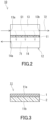
- the first membrane separation device 10 includes a first separation membrane 11 and a tank 12.
- the tank 12 has a first chamber 13 and a second chamber 14.
- the first chamber 13 functions as the feed space to which the aqueous solution S1 is supplied.
- the second chamber 14 functions as the permeation space to which a first permeated fluid 71 is supplied.
- the first permeated fluid 71 is obtained by allowing the aqueous solution S1 to permeate through the first separation membrane 11.
- the first separation membrane 11 is disposed in the tank 12. In the tank 12, the first separation membrane 11 separates the first chamber 13 and the second chamber 14 from each other.
- the first separation membrane 11 extends from one of a pair of wall surfaces of the tank 12 to the other.
- the first chamber 13 has the inlet 13a and the outlet 13b.
- the second chamber 14 has the outlet 14a.
- the inlet 13a of the first chamber 13 is an opening for supplying the aqueous solution S1 to the first membrane separation device 10.
- the outlet 14a of the second chamber 14 is an opening for discharging the first permeated fluid 71 from the first membrane separation device 10.
- the outlet 13b of the first chamber 13 is an opening for discharging, from the first membrane separation device 10, the aqueous solution S1 (a first non-permeated fluid 72) not having permeated through the first separation membrane 11.
- the inlet 13a, the outlet 13b, and the outlet 14a are formed, for example, in wall surfaces of the tank 12.
- the first membrane separation device 10 is suitable for a flow-type (continuous-type) membrane separation method. However, the first membrane separation device 10 may be used for a batch-type membrane separation method.
- the first separation membrane 11 is not particularly limited as long as the first separation membrane 11 allows the organic compound C contained in the aqueous solution S1 to preferentially permeate therethrough.
- the first separation membrane 11 is, for example, a pervaporation membrane that allows the first permeated fluid 71 that is a gas to be generated by a pervaporation method.
- the first separation membrane 11 includes, for example, a separation functional layer 1 and a porous support member 2 supporting the separation functional layer 1.
- the first separation membrane 11 may further include a protective layer (not shown) that protects the separation functional layer 1.
- the separation functional layer 1 is in direct contact with the porous support member 2, for example.
- the first separation membrane 11 has a principal surface 11a, on the separation functional layer side, that is exposed to the first chamber 13 and a principal surface 11b, on the porous support member side, that is exposed to the second chamber 14.
- the separation functional layer 1 is a layer that allows the organic compound C contained in the aqueous solution S1 to preferentially permeate therethrough.
- the separation functional layer 1 includes a hydrophobic material, for example.
- hydrophobic material refers to, for example, a material that has a static contact angle exceeding 90° with respect to water when a 10 ⁇ L drop of the water (temperature 25°C) is dropped on a surface of a specimen composed of the material. Note that the static contact angle with respect to water can be measured using a commercially available contact angle meter.
- hydrophobic material examples include a compound having a siloxane bond (a Si-O-Si bond), an olefin-based polymer, an oil, and a fluorine-based compound.
- the separation functional layer 1 preferably includes a compound having a siloxane bond as the hydrophobic material.
- the compound having a siloxane bond is typically a silicone-based polymer.
- the silicone-based polymer may be a solid or a liquid at 25°C.
- Specific examples of the silicone-based polymer include polydimethylsiloxane (PDMS).
- Specific examples of the olefin-based polymer include polypropylene.
- the oil examples include a hydrocarbon-based oil such as liquid paraffin.
- fluorine-based compound examples include polytetrafluoroethylene (PTFE), polyvinylidene fluoride (PVDF), and tetrafluoroethylene-perfluoroalkyl vinyl ether copolymer (PFA). These hydrophobic materials can be used alone or two or more of them can be used in combination.
- PTFE polytetrafluoroethylene
- PVDF polyvinylidene fluoride
- PFA tetrafluoroethylene-perfluoroalkyl vinyl ether copolymer
- the separation functional layer 1 may include the hydrophobic material as a main component, or may be composed substantially of the hydrophobic material alone.
- the term "main component” means a component having a largest content in the separation functional layer 1 in terms of weight ratio.
- the separation functional layer 1 may include a matrix including the hydrophobic material and a filler dispersed in the matrix.
- the filler is buried in the matrix. In the matrix, all particles of the filler may be spaced from each other or may aggregate partially.
- the filler includes, for example, an inorganic material such as zeolite, silica, or bentonite.
- the zeolite included in the filler is preferably a high-silica zeolite having a high ratio of silica with respect to alumina. Having high resistance to hydrolysis, the high-silica zeolite is suitably used for separating the aqueous solution S1.
- HSZ registered trademark
- HiSiv available from UNION SHOWA K.K.
- USKY available from UNION SHOWA K.K.
- Zeoal registered trademark
- the filler may include a metal organic framework (MOF).
- the metal organic framework is also referred to as a porous coordination polymer (PCP).
- the metal organic framework is preferably hydrophobic.
- the metal organic framework includes a metal ion and an organic ligand, for example. Examples of the metal ion include a Zn ion.
- the organic ligand includes an aromatic ring, for example. Examples of the aromatic ring included in the organic ligand include an imidazole ring. Examples of the organic ligand include 2-methylimidazole. Specific examples of the metal organic framework include ZIF-8.
- the filler is in the form of particles, for example.
- the term "form of particles" herein includes spherical, elliptical, flaky, and fibrous forms.
- An average particle diameter of the filler is, for example, but not particularly limited to, 50 ⁇ m or less, preferably 20 ⁇ m or less, and more preferably 10 ⁇ m or less.
- the lower limit of the average particle diameter of the filler is 0.01 ⁇ m, for example.
- the average particle diameter of the filler can be determined by the following method, for example. First, a cross-section of the separation functional layer 1 is observed using a transmission electron microscope. The area of a specific particle of the filler on the resulting electron microscope image is calculated by image processing.
- the diameter of a circle having the same area as the calculated area is regarded as the particle diameter (the diameter of the particle) of the specific filler particle.
- the particle diameter was calculated for any number (at least 50) of the filler particles, and the average of the calculated values was regarded as the average particle diameter of the filler.
- the content of the filler in the separation functional layer 1 is, for example, 10 wt% or more, preferably 30 wt% or more, and more preferably 40 wt% or more.
- the upper limit of the content of the filler in the separation functional layer 1 is, for example, but not particularly limited to, 70 wt%.
- the content of the matrix in the separation functional layer 1 is, for example, but not particularly limited to, 30 wt% to 90 wt%.
- the separation functional layer 1 has a thickness of, for example, 200 ⁇ m or less, preferably 100 ⁇ m or less, and more preferably 80 ⁇ m or less.
- the separation functional layer 1 may have a thickness of 1.0 ⁇ m or more, 10 ⁇ m or more, and 30 ⁇ m or more.
- the separation functional layer 1 may have a microporous structure with an average pore diameter of less than 0.01 ⁇ m, but may be a dense layer having no pore on its surface.
- porous support member 2 examples include: a nonwoven fabric; porous polytetrafluoroethylene; aromatic polyamide fiber; a porous metal; a sintered metal; porous ceramic; porous polyester; porous nylon; activated carbon fiber; latex; silicone; silicone rubber; a permeable (porous) polymer including at least one selected from the group consisting of polyvinyl fluoride, polyvinylidene fluoride, polyurethane, polypropylene, polyethylene, polystyrene, polycarbonate, polysulfone, polyether ether ketone, polyacrylonitrile, polyimide, and polyphenylene oxide; a metallic foam having an open cell or a closed cell; a polymer foam having an open cell or a closed cell; silica; a porous glass; and a mesh screen.
- the porous support member 2 may be a combination of two or more of these materials.
- the porous support member 2 has an average pore diameter of 0.01 to 0.4 ⁇ m, for example.
- a thickness of the porous support 2 is, for example, but not particularly limited to, 10 ⁇ m or more, preferably 50 ⁇ m or more, and more preferably 100 ⁇ m or more.
- the thickness of the porous support 2 is, for example, 300 ⁇ m or less, and preferably 200 ⁇ m or less.
- the protective layer covers a surface of the separation functional layer 1, for example.
- a material of the protective layer is, for example, but not particularly limited to, a silicone resin.
- the material of the protective layer may be the same as that of the matrix of the separation functional layer 1.
- a thickness of the protective layer is, for example, but not particularly limited to, 5 ⁇ m or more, preferably 10 ⁇ m or more, and more preferably 20 ⁇ m or more.
- the thickness of the protective layer is, for example, 100 ⁇ m or less, and preferably 50 ⁇ m or less.
- the first separation membrane 11 can be produced by, for example, forming the separation functional layer 1 on the porous support member 2. Specifically, a coating liquid containing the materials of the separation functional layer 1 is prepared first.
- the coating liquid may contain, in addition to the filler, a dispersant for dispersing the filler in the coating liquid.
- the coating liquid may further contain a catalyst for curing the compound.
- the coating liquid is applied onto the porous support 2 to obtain a coating. The coating is dried to obtain the separation functional layer 1.
- a separation factor of the first separation membrane 11 for the organic compound C with respect to water is not particularly limited.
- a separation factor ⁇ of the first separation membrane 11 for n-butanol (BuOH) with respect to water may be 10 to 100.
- the separation factor ⁇ can be measured by the following method. First, in a state in which a liquid mixture composed of BuOH and water is in contact with one surface (the principal surface 11a, on the separation functional layer side, of the first separation membrane 11, for example) of the first separation membrane11, a space adjacent to another surface (the principal surface 11b, on the porous support member side, of the first separation membrane 11, for example) of the first separation membrane 11 is decompressed.
- a permeated fluid having permeated through the first separation membrane 11 can be obtained.
- a weight ratio of the water and a weight ratio of the BuOH in the permeated fluid are measured.
- the content of the BuOH in the liquid mixture is 0.5 wt%.
- the liquid mixture in contact with the first separation membrane 11 has a temperature of 30°C.
- the space adjacent to the other surface of the first separation membrane 11 is decompressed to 1.5 kPa.
- the separation factor ⁇ can be calculated by the following formula. Note that in the following formula, X A and X B are respectively a weight ratio of the BuOH and a weight ratio of the water in the liquid mixture.
- a flux of the BuOH permeating through the first separation membrane 11 is, for example, but not particularly limited to, 0.01 (g/min/m 2 ) to 1.0 (g/min/m 2 ).
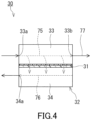
- the second membrane separation device 30 includes a second separation membrane 31 and a tank 32.
- the tank 32 has a third chamber 33 and a fourth chamber 34.
- the third chamber 33 functions as the feed space to which an aqueous phase 75 obtained in the separation vessel 25 is supplied.
- the fourth chamber 34 functions as the permeation space to which a second permeated fluid 76 is supplied.
- the second permeated fluid 76 is obtained by allowing the aqueous phase 75 to permeate through the second separation membrane 31.
- the second separation membrane 31 is disposed in the tank 32. In the tank 32, the second separation membrane 31 separates the third chamber 33 and the fourth chamber 34 from each other.
- the second separation membrane 31 extends from one of a pair of wall surfaces of the tank 32 to the other.
- the third chamber 33 has the inlet 33a and the outlet 33b.
- the fourth chamber 34 has the outlet 34a.
- the inlet 33a of the third chamber 33 is an opening for supplying the aqueous phase 75 to the second membrane separation device 30.
- the outlet 34a of the fourth chamber 34 is an opening for discharging the second permeated fluid 76 from the second membrane separation device 30.
- the outlet 33b of the third chamber 33 is an opening for discharging, from the second membrane separation device 30, the aqueous phase 75 (a second non-permeated fluid 77) not having permeated through the second separation membrane 31.
- the inlet 33a, the outlet 33b, and the outlet 34a are formed, for example, in wall surfaces of the tank 32.
- the second membrane separation device 30 is suitable for a flow-type (continuous-type) membrane separation method.
- the second membrane separation device 30 may be used for a batch-type membrane separation method.
- the second separation membrane 31 may or may not be the same as the first separation membrane 11 except for its membrane area.
- the second separation membrane 31 is, for example, a pervaporation membrane that allows the second permeated fluid 76 that is a gas to be generated by a pervaporation method.
- at least one selected from the group consisting of the first separation membrane 11 and the second separation membrane 31 is a pervaporation membrane, and it is preferable that the first separation membrane 11 and the second separation membrane 31 be each a pervaporation membrane.
- a method for operating the membrane separation system 100 of the present embodiment includes: generating, with the first separation membrane 11, the first permeated fluid 71 from the aqueous solution S1 (a first separation step); phase-separating, with the separation vessel 25, the aqueous solution S2 into an aqueous phase and an organic phase (a second separation step); generating, with the second separation membrane 31, the second permeated fluid 76 from the aqueous phase (a third separation step); and preparing the aqueous solution S2 by mixing the first permeated fluid 71 with the second permeated fluid 76 (a preparation step).
- the first separation step is performed as follows, for example. First, the aqueous solution S1 is supplied to the first chamber 13 of the first membrane separation device 10 via the aqueous solution feed passage 50. This makes it possible to bring the aqueous solution S1 into contact with one surface (the principal surface 11a, for example) of the first separation membrane 11.
- the organic compound C contained in the aqueous solution S1 is not particularly limited as long as it has volatility.
- the term "organic compound having volatility" refers to an organic compound that has a boiling point of 20°C to 260°C, preferably 50 to 260°C, under an atmospheric pressure (101.325 kPa). Note that the organic compound C allows, for example, an aqueous phase and an organic phase to be generated when a concentration of the organic compound C is high in the aqueous solution.
- the number of carbon atoms in the organic compound C is, for example, but not particularly limited to, 10 or less, and may be 8 or less, 6 or less, or even 4 or less.
- the lower limit of the number of carbon atoms in the organic compound C may be 1 or 2.
- the organic compound C has, for example, a functional group including an oxygen atom, such as a hydroxyl group, a carbonyl group, an ether group, and an ester group. In the organic compound C, the number of the functional groups including an oxygen atom is typically one.
- the organic compound C is, for example, at least one selected from the group consisting of an alcohol, ketone, and ester, and preferred is an alcohol.
- the alcohol may be an alkyl alcohol composed only of an alkyl group and a hydroxyl group, or may be an aryl alcohol including an aryl group and a hydroxyl group.
- the alkyl alcohol may be linear, branched, or cyclic. Examples of the alkyl alcohol include n-propanol, n-butanol (BuOH), 2-butanol, isobutanol, t-butanol, and n-pentanol, and preferred is n-butanol.
- Examples of the aryl alcohol include phenol.
- the ketone may be dialkylketone composed only of an alkyl group and a carbonyl group.
- Examples of the dialkylketone include methyl ethyl ketone (MEK) and acetone.
- the ester may be aliphatic alkylester composed only of an alkyl group and an ester group.
- Examples of the aliphatic alkylester include ethyl acetate.
- organic compound C is not limited to those mentioned above.
- the organic compound C may be aromatic hydrocarbon such as benzene, toluene, or xylene.
- the aqueous solution S1 may contain one kind of the organic compound C, or two or more kinds of the organic compounds C.
- the content of the organic compound C in the aqueous solution S1 is, for example, 50 wt% or less, and may be 30 wt% or less, 10 wt% or less, 5 wt% or less, 2 wt% or less, or even 1 wt% or less.
- the lower limit of the content of the organic compound C is, for example, but not particularly limited to, 0.01 wt%.
- the organic compound C may be a fermented product generated by fermentation of a carbon source by a microorganism, or may be an alcohol (a bioalcohol, especially biobutanol), such as n-butanol, generated by a microorganism. That is, the aqueous solution S1 may be a fermented liquid containing the organic compound C as the fermented product. However, the aqueous solution S1 is not limited to the fermented liquid and may be waste water discharged from a chemical plant, etc.
- the aqueous solution S1 may further contain an additional component, such as a microorganism, a carbon source, a nitrogen source, and an inorganic ion, other than water and the organic compound C.
- an additional component such as a microorganism, a carbon source, a nitrogen source, and an inorganic ion, other than water and the organic compound C.
- the microorganism include a bacteria such as Clostridium.
- the carbon source include polysaccharides such as starch, and monosaccharides such as glucose.
- the content of the additional component in the aqueous solution S1 is, for example, but not particularly limited to, 1 wt% to 10 wt%.
- the amount of the aqueous solution S1 to be supplied to the first membrane separation device 10 is not particularly limited and is determined according to the processing capacity of the first membrane separation device 10. In one example, the amount of the aqueous solution S1 to be supplied is 0.5 kg/hr to 500 kg/hr.
- the aqueous solution S1 to be supplied to the first chamber 13 may be heated in advance. In one example, the aqueous solution S1 to be supplied to the first chamber 13 has a temperature of 30°C to 75°C.
- a space adjacent to another surface (the principal surface 11b, for example) of the first separation membrane 11 is decompressed.
- an inside of the second chamber 14 is decompressed via the outlet 14a.
- the inside of the second chamber 14 can be decompressed by, for example, the decompression device provided to the first permeated fluid feed passage 51.
- a pressure in the second chamber 14 is, for example, 50 kPa or less, and may be 20 kPa or less, 10 kPa or less, 5 kPa or less, 3 kPa or less, or even 2 kPa or less.
- the term "pressure" means an absolute pressure unless otherwise noted.
- Decompressing the inside of the second chamber 14 makes it possible to obtain, on the side of the other surface of the first separation membrane 11, the first permeated fluid 71 having a high content of the organic compound C.
- the first permeated fluid 71 is supplied to the second chamber 14.
- the first permeated fluid 71 may be a gas or a liquid in the second chamber 14.
- the first permeated fluid 71 is discharged outside the first membrane separation device 10 via the outlet 14a.
- the first permeated fluid 71 that is a gas is cooled by, for example, the heat exchanger provided to the first permeated fluid feed passage 51, or the like. Thereby, the first permeated fluid 71 is liquefied to obtain the first permeated fluid 71 that is a liquid.
- the content of the organic compound C in the aqueous solution S1 gradually decreases from the inlet 13a toward the outlet 13b in the first chamber 13.
- the aqueous solution S1 processed in the first chamber 13 (the first non-permeated fluid 72) is discharged outside the first membrane separation device 10 via the outlet 13b.
- the first non-permeated fluid 72 is typically a liquid.
- the first separation membrane 11 of the first membrane separation device 10 allows the organic compound C contained in the aqueous solution S1 to preferentially permeate therethrough. Accordingly, the first permeated fluid 71 obtained by the operation of the first membrane separation device 10 has a content of the organic compound C higher than that in the aqueous solution S1 to be supplied to the first membrane separation device 10.
- a ratio of the content (wt%) of the organic compound C in the first permeated fluid 71 with respect to the content (wt%) of the organic compound C in the aqueous solution S1 is, for example, but not particularly limited to, 5 to 50.
- the second separation step is performed as follows, for example.
- the aqueous solution S2 prepared by the later-described preparation step is supplied to the separation vessel 25, or the aqueous solution S2 is prepared in the separation vessel 25 in the preparation step.
- the aqueous solution S2 is an aqueous solution containing the organic compound C.
- the content of the organic compound C in the aqueous solution S2 is not particularly limited as long as the aqueous solution S2 can be phase-separated into an aqueous phase and an organic phase, and it is, for example, 7 wt% or more, and may be 8 wt% or more, 10 wt% or more, 20 wt% or more, 30 wt% or more, or even 50 wt% or more.
- the upper limit of the content of the organic compound C in the aqueous solution S2 is, for example, but not particularly limited to, 80 wt%.
- the aqueous solution S2 can be phase-separated into an aqueous phase and an organic phase when the content of the n-butanol in the aqueous solution S2 is 7 wt% or more.
- the aqueous solution S2 is left at rest in the separation vessel 25. Thereby, the aqueous solution S2 is phase-separated into an aqueous phase and an organic phase.
- the aqueous phase has a content of water higher than that in the aqueous solution S2 and contains the organic compound C.
- the aqueous phase contains, for example, water as a main component, and the content of the water is 50 wt% to 95wt%, for example.
- the content of the organic compound C in the aqueous phase is lower than the content of the organic compound C in the aqueous solution S2 and is, for example, less than 50 wt%, and may be 30 wt% or less, 10 wt% or less, or even 7 wt% or less.
- the organic compound C may be saturated in the aqueous phase. In the case where the organic compound C is n-butanol, the content of the n-butanol in the aqueous phase may be approximately 7 wt%.
- the content of the organic compound C in the organic phase is higher than the content of the organic compound C in the aqueous solution S2 and is, for example, 50 wt% or more, and may be 60 wt% or more, 70 wt% or more, or even80 wt% or more.
- the organic phase contains water in addition to the organic compound C, for example.
- the content of the water in the organic phase is lower than the content of water in the aqueous solution S2 and is, for example, less than 50 wt%, and may be 40 wt% or less, 30 wt% or less, or even 20 wt% or less.
- the aqueous phase is discharged outside the separation vessel 25 via the outlet 27.
- the organic phase is discharged outside the separation vessel 25 via the outlet 28.
- the operating method of the present embodiment makes it possible to obtain the organic compound C at a relatively high purity by recovering the organic phase.
- the organic phase may also be distilled in the operating method of the present embodiment in order to increase the content of the organic compound C in the organic phase.
- the third separation step is performed as follows, for example.
- the aqueous phase 75 obtained in the second separation step is supplied to the third chamber 33 of the second membrane separation device 30 via the aqueous phase feed passage 53. This makes it possible to bring the aqueous phase 75 into contact with one surface of the second separation membrane 31.
- the amount of the aqueous phase 75 to be supplied to the second membrane separation device 30 is not particularly limited and is determined according to the processing capacity of the second membrane separation device 30. In one example, the amount of the aqueous phase 75 to be supplied is 0.5 kg/hr to 500 kg/hr.
- the aqueous phase 75 to be supplied to the third chamber 33 may be heated in advance. In one example, the aqueous phase 75 to be supplied to the third chamber 33 has a temperature of 30°C to 75°C.
- a space adjacent to another surface of the second separation membrane 31 is decompressed.
- an inside of the fourth chamber 34 is decompressed via the outlet 34a.
- the inside of the fourth chamber 34 can be decompressed by, for example, the decompression device provided to the second permeated fluid feed passage 55 or the first permeated fluid feed passage 51.
- a pressure in the fourth chamber 34 is, for example, 50 kPa or less, and may be 20 kPa or less, 10 kPa or less, 5 kPa or less, 3 kPa or less, or even 2 kPa or less.
- Decompressing the inside of the fourth chamber 34 makes it possible to obtain, on the side of the other surface of the second separation membrane 31, the second permeated fluid 76 having a high content of the organic compound C.
- the second permeated fluid 76 is supplied to the fourth chamber 34.
- the second permeated fluid 76 may be a gas or a liquid in the fourth chamber 34.
- the second permeated fluid 76 is discharged outside the second membrane separation device 30 via the outlet 34a.
- the second permeated fluid 76 that is a gas is cooled by, for example, the heat exchanger provided to the second permeated fluid feed passage 55 or the first permeated fluid feed passage 51, or the like. Thereby, the second permeated fluid 76 is liquefied to obtain the second permeated fluid 76 that is a liquid.
- the content of the organic compound C in the aqueous phase 75 gradually decreases from the inlet 33a toward the outlet 33b in the third chamber 33.
- the aqueous phase 75 (the second non-permeated fluid 77) processed in the third chamber 33 is discharged outside the second membrane separation device 30 via the outlet 33b.
- the second non-permeated fluid 77 is typically a liquid.
- the second separation membrane 31 of the second membrane separation device 30 allows the organic compound C contained in the aqueous phase 75 to preferentially permeate therethrough. Accordingly, the second permeated fluid 76 obtained by the operation of the second membrane separation device 30 has a content of the organic compound C higher than that in the aqueous phase 75 to be supplied to the second membrane separation device 30.
- a ratio of the content (wt%) of the organic compound C in the second permeated fluid 76 with respect to the content (wt%) of the organic compound C in the aqueous phase 75 is, for example, but not particularly limited to, 5 to 50.
- the content of the organic compound C in the second non-permeated fluid 77 is lower than the content of the organic compound C in the aqueous phase 75 to be supplied to the second membrane separation device 30 and is, for example, 5 wt% or less, and may be 2 wt% or less or even 1 wt% or less.
- the second non-permeated fluid 77 in which the content of the organic compound C is 2 wt% or less tends to be able to inhibit the fermentation by a microorganism from stopping in the aqueous solution S1 even when being mixed with the aqueous solution S1 as the fermented liquid in the later-described mixing step.
- the lower limit of the content of the organic compound C in the second non-permeated fluid 77 is, for example, but not particularly limited to, 0.001 wt%.
- a preparation step is performed as follows, for example. First, the second permeated fluid 76 is supplied to the first permeated fluid feed passage 51 or the separation vessel 25 via the second permeated fluid feed passage 55. Thereby, the first permeated fluid 71 is mixed with the second permeated fluid 76 in the first permeated fluid feed passage 51 or the separation vessel 25, and thereby the aqueous solution S2 can be prepared.
- the second permeated fluid 76 that is a liquid may be mixed with the first permeated fluid 71 that is a liquid to prepare the aqueous solution S2, or a gas mixture obtained by mixing the second permeated fluid 76 that is a gas with the first permeated fluid 71 that is a gas may be cooled to prepare the aqueous solution S2.
- the aqueous solution S2 may be composed only of the first permeated fluid 71 and the second permeated fluid 76, or may contain, in addition to these fluids, the distillate obtained in the later-described distillation step.
- the second non-permeated fluid 77 preferably has a content of the organic compound C comparable to that in the aqueous solution S1.
- a ratio of the content of the organic compound C in the second non-permeated fluid 77 with respect to the content of the organic compound C in the aqueous solution S1 discharged from the tank 20 is 80% to 120%. In this case, it tends to be possible to suppress sufficiently the energy required to operate the membrane separation system 100.
- the operating method of the present embodiment may further include a distillation step of distilling the organic phase obtained in the second separation step.
- the distillation step is performed as follows, for example. First, the organic phase is supplied to the distillation device 40 via the organic phase feed passage 54. The organic phase can be distilled in the distillation device 40.
- the distillation step it is possible to further increase the content of the organic compound C in the organic phase by heating the water together with the organic compound C.
- the distillation step makes it possible to increase the content (purity) of the organic compound C in the organic phase to, for example, 80 wt% or more, 90 wt% or more, 95 wt% or more, or even 99 wt% or more.
- the residue obtained by the distillation step (the organic phase after being distilled) is discharged outside the distillation device 40 via the outlet 42.
- the operating method of the present embodiment makes it possible to obtain the organic compound C at a high purity by recovering this residue.
- the distillate obtained by distilling the organic phase has a content of the organic compound C lower than that in the organic phase supplied to the distillation device 40, and a content of water higher than that in the organic phase.
- the content of the organic compound C in the distillate is, for example, but not particularly limited to, 30 wt% to 70wt%.
- the distillate obtained by the distillation step may be delivered to the first permeated fluid feed passage 51 via the distillate discharge passage 58 to be mixed with the first permeated fluid 71 and the second permeated fluid 76.
- the membrane separation system 100 of the present embodiment includes the first membrane separation device 10, the separation vessel 25, the second membrane separation device 30, the first permeated fluid feed passage 51, and the second permeated fluid feed passage 55, and is configured in such a manner that the second permeated fluid 76 is supplied to the first permeated fluid feed passage 51 or the separation vessel 25 via the second permeated fluid feed passage 55.
- the membrane separation system 100 as just mentioned is suitable for efficiently separating the organic compound C from the aqueous solution S1.
- the energy required for operation tends to be more suppressed in the membrane separation system 100 of the present embodiment than in the case where the aqueous phase obtained in the separation vessel 25 is distilled by using an additional distillation device instead of the second membrane separation device 30.
- the membrane separation system 100 of the present embodiment is more suitable for suppressing the energy required for operation while reducing the membrane areas of the separation membranes required to separate the aqueous solution S1, etc. than a membrane separation system (such as the later-described membrane separation system 200 of Calculation Example 1 ( FIG. 7 )) in which the aqueous phase obtained in the separation vessel 25 is mixed with the aqueous solution S1 without using the second membrane separation device 30.
- a membrane separation system such as the later-described membrane separation system 200 of Calculation Example 1 ( FIG. 7 )
- the first membrane separation device 10 may be a spiral membrane element, a hollow fiber membrane element, a disk tube membrane element in which a plurality of pervaporation membranes are laminated, a plate-and-flame membrane element, or the like.
- FIG. 5 shows a spiral membrane element.
- a first membrane separation device 15 of FIG. 5 includes a central tube 16 and a laminate 17.
- the laminate 17 includes the first separation membrane 11.
- the central tube 16 has a cylindrical shape.
- the central tube 16 has a surface with a plurality of holes or slits to allow the first permeated fluid 71 to flow into the central tube 16.
- Examples of a material of the central tube 16 include: a resin such as an acrylonitrile-butadiene-styrene copolymer resin (an ABS resin), a polyphenylene ether resin (a PPE resin), or a polysulfone resin (a PSF resin); and a metal such as stainless steel or titanium.
- the central tube 16 has an inner diameter in a range of, for example, 20 to 100 mm.
- the laminate 17 further includes a feed-side flow passage material 18 and a permeation-side flow passage material 19 in addition to the first separation membrane 11.
- the laminate 17 is wound around the central tube 16.
- the first membrane separation device 15 may further include an exterior material (not shown).
- a resin net, woven fabric, or knitted fabric composed of polyethylene, polypropylene, polyethylene terephthalate (PET), polyphenylene sulfide (PPS), or an ethylene-chlorotrifluoroethylene copolymer (ECTFE) can be used, for example.
- PET polyethylene terephthalate
- PPS polyphenylene sulfide
- ECTFE ethylene-chlorotrifluoroethylene copolymer
- a method for operating the first membrane separation device 15 is carried out as follows, for example. First, the aqueous solution S1 is supplied into an end of the wound laminate 17. A space inside the central tube 16 is decompressed. The first permeated fluid 71 having permeated through the first separation membrane 11 of the laminate 17 thereby moves into the central tube 16. The first permeated fluid 71 is discharged outside via the center tube 16. The aqueous solution S1 processed by the first membrane separation device 15 (the first non-permeated fluid 72) is discharged outside from another end of the wound laminate 17.
- the second membrane separation device 30 may also be a spiral membrane element, a hollow fiber membrane element, a disk tube membrane element in which a plurality of pervaporation membranes are laminated, a plate-and-flame membrane element, or the like.
- the second membrane separation device 30 may be a spiral membrane element having the same configuration as that of the first membrane separation device 15.
- the first membrane separation device 10 has two membrane separation units 10a and 10b, and a connection passage 5 connecting the two membrane separation units 10a and 10b to each other.
- the second non-permeated fluid discharge passage 56 is connected to the connection passage 5 at a connecting point 64.
- the first permeated fluid feed passage 51 has a first portion 51a and a second portion 51b.
- the membrane separation system 110 has the same configuration as that of the membrane separation system 100 of Embodiment 1. Therefore, the elements common between the membrane separation system 100 of Embodiment 1 and the membrane separation system 110 of the present embodiment are denoted by the same reference numerals, and the description of such elements may be omitted. That is, the description of each of the following embodiments is applicable to the other embodiment unless technical inconsistency occurs. Furthermore, the features of the embodiments may be combined with each other unless technical inconsistency occurs.
- Each of the two membrane separation units 10a and 10b has, for example, the same configuration as that of the first membrane separation device 10 of the membrane separation system 100 of Embodiment 1.
- the membrane separation unit 10a has a first separation membrane 11A and further has, for example, a feed space (a first chamber) and a permeation space (a second chamber) separated from each other by the first separation membrane 11A.
- the aqueous solution feed passage 50 is connected to an aqueous solution inlet (the inlet 13a) of the membrane separation unit 10a.
- the aqueous solution S1 can be supplied to the feed space of the membrane separation unit 10a via the inlet 13a.
- the first portion 51a of the first permeated fluid feed passage 51 is connected to a permeated fluid outlet (the outlet 14a) of the membrane separation unit 10a.
- the first permeated fluid 71 can be discharged outside from the permeation space of the membrane separation unit 10a via the outlet 14a.
- the connection passage 5 is connected to an aqueous solution outlet (the outlet 13b) of the membrane separation unit 10a.
- the aqueous solution S1 processed in the membrane separation unit 10a can be discharged outside from the feed space of the membrane separation unit 10a via the outlet 13b.
- the membrane separation unit 10b has a first separation membrane 11B and further has, for example, a feed space (a first chamber) and a permeation space (a second chamber) separated from each other by the first separation membrane 11B.
- the connection passage 5 is connected to an aqueous solution inlet (an inlet 13c) of the membrane separation unit 10b.
- the aqueous solution S1 can be supplied to the feed space of the membrane separation unit 10b via the inlet 13c. In such a manner, the connection passage 5 connects the feed space of the membrane separation unit 10a to the feed space of the membrane separation unit 10b.
- the second portion 51b of the first permeated fluid feed passage 51 is connected to a permeated fluid outlet (an outlet 14b) of the membrane separation unit 10b.
- the first permeated fluid 71 can be discharged outside from the permeation space of the membrane separation unit 10b via the outlet 14b.
- the first non-permeated fluid discharge passage 52 is connected to an aqueous solution outlet (an outlet 13d) of the membrane separation unit 10b.
- the aqueous solution S1 (the first non-permeated fluid 72) processed in the membrane separation unit 10b can be discharged outside from the feed space of the membrane separation unit 10b via the outlet 13d.
- the first separation membrane 11A of the membrane separation unit 10a may or may not be the same as the first separation membrane 11B of the membrane separation unit 10b except for its membrane area.
- a ratio of the membrane area (m 2 ) of the first separation membrane 11A with respect to a total value (m 2 ) of the membrane area of the first separation membrane 11A and a membrane area of the first separation membrane 11B is, for example, but not particularly limited to, 20% to 80%.
- first membrane separation device 10 may further have an additional membrane separation unit other than the membrane separation units 10a and 10b.
- the number of the membrane separation units is, for example, but not particularly limited to, 2 to 5.
- the second portion 51b joins the first portion 51a at a joining point 65.
- the first permeated fluid 71 discharged from the membrane separation unit 10a can be mixed with the first permeated fluid 71 discharged from the membrane separation unit 10b.
- the second non-permeated fluid discharge passage 56 is connected to the connection passage 5 at the connecting point 64.
- the second non-permeated fluid 77 can be mixed with the aqueous solution S1 discharged from the membrane separation unit 10a.
- the content of the organic compound C in the second non-permeated fluid 77 is preferably comparable to the content of the organic compound C in the aqueous solution S1 discharged from the membrane separation unit 10a.
- a ratio of the content of the organic compound C in the second non-permeated fluid 77 with respect to the content of the organic compound C in the aqueous solution S1 discharged from the membrane separation unit 10a is 80% to 120%. In this case, it tends to be possible to suppress sufficiently the energy required to operate the membrane separation system 110.
- a separation membrane (a pervaporation membrane) was produced by the following method.
- a coating liquid was prepared by mixing 1.650 kg (solids concentration: 30 wt%) of a silicone resin (YSR3022 available from Momentive Performance Materials Japan LLC.), 2.805 kg of toluene, 0.495 kg of a high-silica zeolite (HiSiv 3000 available from UNION SHOWA K.K.), 0.0495 kg of a silicone curing catalyst (YC6831 available from Momentive Performance Materials Japan LLC.), and 0.0495 kg of acetylacetone as a curing retardant.
- a silicone resin YSR3022 available from Momentive Performance Materials Japan LLC.
- HiSiv 3000 available from UNION SHOWA K.K.
- a silicone curing catalyst YC6831 available from Momentive Performance Materials Japan LLC.
- acetylacetone as a curing retardant.
- the coating liquid was applied onto a porous support (RS-50 available from Nitto Denko Corporation) having a thickness of 150 ⁇ m to obtain a coating (thickness: 500 ⁇ m).
- the coating was heated at 90°C for 4 minutes and then dried to produce a separation functional layer having a thickness of 50 ⁇ m.
- the weight ratio between the silicone resin and the high-silica zeolite was 50:50 in the separation functional layer. Thus, a separation membrane was obtained.
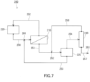
- the operation of a membrane separation system 200 shown in FIG. 7 was simulated using the produced separation membrane.
- the membrane separation system 200 included a first membrane separation device 210, a tank 220, a separation vessel 225, a distillation device 240, an aqueous solution feed passage 250, a first permeated fluid feed passage 251, an aqueous phase feed passage 253, etc.
- the membrane separation system 200 had the same configuration as that of the membrane separation system 100 shown in FIG. 1 , except that the second membrane separation device was omitted and the aqueous phase feed passage 253 was connected to the aqueous solution feed passage 250.
- the aqueous solution S1 to be delivered from the tank 220 is an aqueous solution containing n-butanol at a content of 0.8 wt%.
- the content of the n-butanol in the non-permeated fluid discharged from the first membrane separation device 210 is 0.08 wt%.
- the content of the n-butanol in the aqueous phase generated in the separation vessel 225 is 7 wt%.
- the content of the n-butanol in the organic phase generated in the separation vessel 225 is 80 wt%.
- the recovery amount of the n-butanol is 250 kg/h
- the content (purity) of the n-butanol is 99.5 wt%
- the recovery rate of the n-butanol is 90%.
- the first membrane separation device 210 In the operation of the first membrane separation device 210, it was assumed to obtain the permeated fluid that was a gas by decompressing the inside of the permeation space while heating the aqueous solution S1, and to cool the obtained permeated fluid in the chiller to liquefy it.
- the operation of the membrane separation system 100 shown in FIG. 1 was simulated using the produced separation membrane. Specifically, it was assumed to use the produced separation membrane for each of the first separation membrane 11 included in the first membrane separation device 10 and the second separation membrane 31 included in the second membrane separation device 30 in the membrane separation system 100.
- the aqueous solution S1 to be delivered from the tank 20 is an aqueous solution containing n-butanol at a content of 0.8 wt%.
- the content of the n-butanol in the first non-permeated fluid 72 discharged from the first membrane separation device 10 is 0.08 wt%.
- the content of the n-butanol in the aqueous phase generated in the separation vessel 25 is 7 wt%.
- the content of the n-butanol in the organic phase generated in the separation vessel 25 is 80 wt%.
- the recovery amount of the n-butanol is 250 kg/h
- the content (purity) of the n-butanol is 99.5 wt%
- the recovery rate of the n-butanol is 90%.
- the membrane area of the second separation membrane 31 was varied and the impact thereof was observed.
- the operation of the membrane separation system 110 shown in FIG. 6 was simulated using the produced separation membrane. Specifically, it was assumed to use the produced separation membrane for each of the first separation membrane 11A and the first separation membrane 11B included in the first membrane separation device 10 and the second separation membrane 31 included in the second membrane separation device 30 in the membrane separation system 110.
- the aqueous solution S1 to be delivered from the tank 20 is an aqueous solution containing n-butanol at a content of 0.8 wt%.
- the content of the n-butanol in the aqueous solution S1 discharged from the membrane separation unit 10a is 0.2 wt%.
- the content of the n-butanol in the first non-permeated fluid 72 discharged from the membrane separation unit 10b is 0.08 wt%.
- the content of the n-butanol in the aqueous phase generated in the separation vessel 25 is 7 wt%.
- the content of the n-butanol in the organic phase generated in the separation vessel 25 is 80 wt%.
- the recovery amount of the n-butanol is 250 kg/h
- the content (purity) of the n-butanol is 99.5 wt%
- the recovery rate of the n-butanol is 90%.
- the membrane area of the second separation membrane 31 was varied and the impact thereof was observed.
- Second membrane separation device Membrane area of second separation membrane (m 2 ) 10605 13532 15146 15930 17383 28386 Energy consumed (kW) 190 225 244 252 272 405 Concentration of BuOH in second non-permeated fluid (wt%) 1.2 0.44 0.25 0.19 0.14 0.006 Energy consumed by first membrane separation device (kW) 2973 2593 2474 2418 2460 2321 Energy consumed by chiller(s) (kW) 3271 2914 2810 2761 2825 2819 Total value of membrane areas (m 2 ) (*1) 157442 141169 136877 134880 138315 142504 Energy required for operating the system (kW) 6572 5869 5666 5569 5695 5682 (*1) The total value of the membrane area of the first separation membrane 11A, that of the first separation membrane 11B, and that of the second separation membrane 31.
- the energy consumed by the membrane separation device reflects the energy required to heat the aqueous solution S1 or the aqueous phase to be supplied to the membrane separation device, and the like. This energy is determined in accordance with the membrane area of the separation membrane, the energy required to evaporate the water and n-butanol, and the like.
- the energy consumed by the membrane separation device tends to increase as the amount of water contained in the permeated fluid increases.
- the energy consumed by the chiller(s) reflects the energy required to cool and liquefy the permeated fluid that is a gas and that is obtained in each membrane separation device, and the like.
- This energy is determined in accordance with the flow rate of the permeated fluid, the energy required to liquefy the water and n-butanol, and the like.
- the energy consumed by the chiller(s) tends to increase as the amount of the water contained in the permeated fluid increases.
- the energy required to operate the system reflects not only the energies consumed by each membrane separation device and chiller but also the energy consumed by the distillation device, and the like.
- the membrane separation system 100 shown in FIG. 1 and the membrane separation system 110 shown in FIG. 6 are more suitable for suppressing the energy required for operation while reducing the membrane areas of the separation membranes required to separate the aqueous solution S1, etc. than the membrane separation system 200 shown in FIG. 7 .
- This result reveals that the membrane separation system of the present embodiment is suitable for efficiently separating a volatile organic compound from an aqueous solution containing the organic compound.
- the membrane separation system 300 included a first membrane separation device 310, a tank 320, a separation vessel 325, a second membrane separation device 330, an additional separation vessel 335, a distillation device 340, an aqueous solution feed passage 350, a first permeated fluid feed passage 351, an aqueous phase feed passage 353, an organic phase feed passage 354, a second permeated fluid feed passage 355, a distillate discharge passage 358, etc.
- the membrane separation system 300 had the same configuration as that of the membrane separation system 100 shown in FIG.
- the membrane separation system 300 included the additional separation vessel 335, the second permeated fluid feed passage 355 was connected to the additional separation vessel 335, and so on. It was assumed to use the produced separation membrane for each of the first separation membrane included in the first membrane separation device 310 and the second separation membrane included in the second membrane separation device 330 in the membrane separation system 300.
- the separation vessel 335 is a vessel for phase-separating the second permeated fluid discharged from the second membrane separation device 330.
- the second permeated fluid that is a liquid is left at rest in the additional separation vessel 335, the second permeated fluid is phase-separated into an aqueous phase and an organic phase.
- the membrane separation system 300 is connected to the additional separation vessel 335 and the aqueous phase feed passage 353, and further includes an additional aqueous phase feed passage 359 for supplying the aqueous phase from the additional separation vessel 335 to the aqueous phase feed passage 353.
- the additional aqueous phase feed passage 359 is connected to the aqueous phase feed passage 353 at a connecting point 364.
- the organic phase feed passage 354 has a first portion 354a and a second portion 354b.
- the second portion 354b is a passage connected to the additional separation vessel 335 and the distillation device 340 and configured to supply the organic phase from the additional separation vessel 335 to the distillation device 340.
- the first portion 354a is a passage connected to the separation vessel 325 and the second portion 354b and configured to supply the organic phase from the separation vessel 325 to the second portion 354b.
- the first portion 354a is connected to the second portion 354b at a connecting point 365.
- the distillate discharge passage 358 is connected not to the first permeated fluid feed passage 351 but to the separation vessel 325.
- the aqueous solution S1 to be delivered from the tank 320 is an aqueous solution containing n-butanol at a content of 0.8 wt%.
- the content of the n-butanol in the first non-permeated fluid discharged from the first membrane separation device 310 is 0.08 wt%.
- the content of the n-butanol in the aqueous phase generated in each of the separation vessel 325 and the additional separation vessel 335 is 7 wt%.
- the content of the n-butanol in the organic phase generated in each of the separation vessel 325 and the additional separation vessel 335 is 80 wt%.
- the recovery amount of the n-butanol is 250 kg/h
- the content (purity) of the n-butanol is 99.5 wt%
- the recovery rate of the n-butanol is 90%.
- Calculation Example 13 Calculation Example 14 Second membrane separation device Membrane area of second separation membrane (m 2 ) 13399 11351 Concentration of BuOH in second non-permeated fluid (wt%) 0.3 0.7 Concentration of BuOH in first permeated fluid 6.6 6.8 Phase separation in separation vessel Impossible Impossible
- the content of the organic compound C in the first permeated fluid can be increased by decreasing the membrane area of the second separation membrane to be less than that in Calculation Example 14. In this case, however, the energy required to operate the membrane separation system 300 and the membrane area of the first separation membrane tend to increase significantly.
- the operation of the membrane separation system 200 shown in FIG. 7 was simulated under operating conditions different from those in Calculation Example 1, and the energy required to operate the membrane separation system 200 and the membrane area of the first separation membrane were calculated.
- Symmetry a process modeling software available from Schlumberger Ltd., was used for the calculations.
- UNIFAC was used as the thermodynamic model.
- the conditions for supplying the aqueous solution S1, and the organic phase and the aqueous phase in the separation vessel 225 were set as follows. Note that in Calculation Example 15, it was assumed to discharge the non-permeated fluid outside the membrane separation system 200 without connecting the first non-permeated fluid discharge passage 252 to the tank 220. Furthermore, in Calculation Example 15, it was assumed to recover the organic phase generated in the separation vessel 225 without operating the distillation device 240.
- the permeated fluid that was a gas was obtained by decompressing the inside of the permeation space to 1.5 kPa while heating the aqueous solution S1 to 40°C. It was assumed that the permeated fluid that was a gas had a flow rate of 1387 kg/h and the content of the MEK therein was 37.7 wt%. It was assumed that the non-permeated fluid had a flow rate of 30914 kg/h and the content of the MEK therein was 0.05 wt%.
- the operation of the membrane separation system 100 shown in FIG. 1 was simulated under operating conditions different from those in Calculation Example 2, and the energy required to operate the membrane separation system 100 and the membrane area of the first separation membrane were calculated.
- Symmetry a process modeling software available from Schlumberger Ltd., was used for the calculations.
- UNIFAC was used as the thermodynamic model.
- the conditions for supplying the aqueous solution S1, and the organic phase and the aqueous phase in the separation vessel 25 were set as follows. Note that in Calculation Example 16, it was assumed to discharge the first non-permeated fluid outside the membrane separation system 100 without connecting the first non-permeated fluid discharge passage 52 to the tank 20. Furthermore, in Calculation Example 16, it was assumed to recover the organic phase generated in the separation vessel 25 without operating the distillation device 40.
- the first membrane separation device 10 In the operation of the first membrane separation device 10, it was assumed to obtain the first permeated fluid that was a gas by decompressing the inside of the permeation space to 1.5 kPa while heating the aqueous solution S1 to 40°C. It was assumed that the first permeated fluid that was a gas had a flow rate of 1037 kg/h and the content of the MEK therein was 29.3 wt%. It was assumed that the first non-permeated fluid had a flow rate of 30914 kg/h and the content of the MEK therein was 0.05 wt%.
- the aqueous solution S2 obtained by mixing the first permeated fluid with the second permeated fluid had a flow rate of 1242 kg/h and the content of the MEK therein was 39.6 wt%.
- the energy required was calculated in the case where the aqueous solution S1 was supplied to a distillation column under the conditions for supplying the aqueous solution S1 in Calculation Examples 15 and 16 and the distillation was performed in the distillation column. Symmetry, a process modeling software available from Schlumberger Ltd., was used for the calculations. UNIFAC was used as the thermodynamic model.
- the conditions for the distillation, and the distillate and the residue (the aqueous solution S1 after being distilled) to be obtained by the distillation were set as follows. Note that it was assumed to recover the distillate in Calculation Example 17.
- the membrane separation system of the present embodiment is suitable for efficiently separating a volatile organic compound from an aqueous solution containing the organic compound.
Landscapes
- Chemical & Material Sciences (AREA)
- Engineering & Computer Science (AREA)
- Life Sciences & Earth Sciences (AREA)
- Chemical Kinetics & Catalysis (AREA)
- Organic Chemistry (AREA)
- Biotechnology (AREA)
- Wood Science & Technology (AREA)
- Zoology (AREA)
- Bioinformatics & Cheminformatics (AREA)
- Health & Medical Sciences (AREA)
- Biochemistry (AREA)
- General Engineering & Computer Science (AREA)
- General Health & Medical Sciences (AREA)
- Genetics & Genomics (AREA)
- Microbiology (AREA)
- Water Supply & Treatment (AREA)
- Biomedical Technology (AREA)
- Sustainable Development (AREA)
- General Chemical & Material Sciences (AREA)
- Separation Using Semi-Permeable Membranes (AREA)
Abstract
Description
- The present invention relates to a membrane separation system and a method for operating a membrane separation system.
- There have been developed methods for producing a volatile organic compound (a fermented product), such as an alcohol, by fermenting a carbon source, such as glucose, by using a microorganism. The fermentation of a carbon source is carried out in an aqueous solution, for example. In this method, the fermentation by a microorganism stops in some cases when the content of the fermented product in the aqueous solution increases. In order to continue the production of the fermented product by a microorganism, it is necessary to separate the fermented product from the aqueous solution.
- As an example of the method for separating a volatile organic compound from an aqueous solution containing the organic compound, a pervaporation method using a separation membrane can be mentioned. The pervaporation method is suitable for separating a volatile organic compound from an aqueous solution containing various substances. By combining a membrane separation device that performs the pervaporation method with a fermenter that produces a fermented product, it is possible to produce a fermented product continuously. For example,
Patent Literature 1 discloses a membrane separation system obtained by combining a membrane separation device with a fermenter. - Patent Literature 1:
JP 2010-161987 A - There is a need for a new membrane separation system suitable for efficiently separating a volatile organic compound from an aqueous solution containing the organic compound.
- The present invention provides a membrane separation system including:
- a first membrane separation device having a first separation membrane that allows a first permeated fluid to be generated from an aqueous solution S1 containing a volatile organic compound, the first permeated fluid having a content of the organic compound higher than that in the aqueous solution S1;
- a separation vessel for phase-separating an aqueous solution S2 containing the first permeated fluid into an aqueous phase having a content of water higher than that in the aqueous solution S2 and containing the organic compound and an organic phase having a content of the organic compound higher than that in the aqueous solution S2;
- a second membrane separation device having a second separation membrane that allows a second permeated fluid to be generated from the aqueous phase, the second permeated fluid having a content of the organic compound higher than that in the aqueous phase;
- a first permeated fluid feed passage connected to the first membrane separation device and the separation vessel and configured to supply the first permeated fluid from the first membrane separation device to the separation vessel; and
- a second permeated fluid feed passage connected to the second membrane separation device and at least one selected from the group consisting of the first permeated fluid feed passage and the separation vessel and configured to supply the second permeated fluid from the second membrane separation device to the first permeated fluid feed passage and/or the separation vessel.
- The present invention further provides a method for operating a membrane separation system including a first membrane separation device having a first separation membrane, a separation vessel, and a second membrane separation device having a second separation membrane, the method including:
- generating, with the first separation membrane, a first permeated fluid from an aqueous solution S1 containing a volatile organic compound, the first permeated fluid having a content of the organic compound higher than that in the aqueous solution S1;
- phase-separating, with the separation vessel, an aqueous solution S2 containing the first permeated fluid into an aqueous phase having a content of water higher than that in the aqueous solution S2 and containing the organic compound and an organic phase having a content of the organic compound higher than that in the aqueous solution S2;
- generating, with the second separation membrane, a second permeated fluid from the aqueous phase, the second permeated fluid having a content of the organic compound higher than that in the aqueous phase; and
- preparing the aqueous solution S2 by mixing the first permeated fluid with the second permeated fluid.
- The present invention can provide a new membrane separation system suitable for efficiently separating a volatile organic compound from an aqueous solution containing the organic compound.
-
-
FIG. 1 is a schematic configuration diagram of a membrane separation system ofEmbodiment 1. -
FIG. 2 is a schematic cross-sectional view showing an example of a first membrane separation device. -
FIG. 3 is a schematic cross-sectional view of a separation membrane included in the first membrane separation device. -
FIG. 4 is a schematic cross-sectional view showing an example of a second membrane separation device. -
FIG. 5 is a perspective view schematically showing another example of the first membrane separation device. -
FIG. 6 is a schematic configuration diagram of a membrane separation system ofEmbodiment 2. -
FIG. 7 is a schematic configuration diagram of a membrane separation system of Calculation Example 1. -
FIG. 8 is a schematic configuration diagram of a membrane separation system of Calculation Examples 13 and 14. - A membrane separation system according to a first aspect of the present invention includes:
- a first membrane separation device having a first separation membrane that allows a first permeated fluid to be generated from an aqueous solution S1 containing a volatile organic compound, the first permeated fluid having a content of the organic compound higher than that in the aqueous solution S1;
- a separation vessel for phase-separating an aqueous solution S2 containing the first permeated fluid into an aqueous phase having a content of water higher than that in the aqueous solution S2 and containing the organic compound and an organic phase having a content of the organic compound higher than that in the aqueous solution S2;
- a second membrane separation device having a second separation membrane that allows a second permeated fluid to be generated from the aqueous phase, the second permeated fluid having a content of the organic compound higher than that in the aqueous phase;
- a first permeated fluid feed passage connected to the first membrane separation device and the separation vessel and configured to supply the first permeated fluid from the first membrane separation device to the separation vessel; and
- a second permeated fluid feed passage connected to the second membrane separation device and at least one selected from the group consisting of the first permeated fluid feed passage and the separation vessel and configured to supply the second permeated fluid from the second membrane separation device to the first permeated fluid feed passage and/or the separation vessel.
- According to a second aspect of the present invention, for example, in the membrane separation system according to the first aspect, the aqueous solution S2 is prepared by mixing the first permeated fluid with the second permeated fluid.
- According to a third aspect of the present invention, for example, the membrane separation system according to the first or second aspect further includes a tank for storing the aqueous solution S1 to be supplied to the first membrane separation device.
- According to a fourth aspect of the present invention, for example, in the membrane separation system according to the third aspect, the organic compound is a fermented product generated by a microorganism, and the tank is a fermenter for generating the organic compound.
- According to a fifth aspect of the present invention, for example, in the membrane separation system according to the third or fourth aspect, the first separation membrane allows a first non-permeated fluid to be generated from the aqueous solution S1, the first non-permeated fluid having a content of the organic compound lower than that in the aqueous solution S1, the membrane separation system further includes a first non-permeated fluid discharge passage connected to the first membrane separation device and configured to discharge the first non-permeated fluid from the first membrane separation device, and the first non-permeated fluid discharge passage is connected to the tank.
- According to a sixth aspect of the present invention, for example, in the membrane separation system according to any one of the first to fifth aspects, the second separation membrane allows a second non-permeated fluid to be generated from the aqueous phase, the second non-permeated fluid having a content of the organic compound lower than that in the aqueous phase, and the membrane separation system further includes a second non-permeated fluid discharge passage connected to the second membrane separation device and configured to discharge the second non-permeated fluid from the second membrane separation device.
- According to a seventh aspect of the present invention, for example, the membrane separation system according to the sixth aspect further includes an aqueous solution feed passage connected to the first membrane separation device and configured to supply the aqueous solution S1 to the first membrane separation device, wherein the second non-permeated fluid discharge passage is connected to the aqueous solution feed passage.
- According to an eighth aspect of the present invention, for example, in the membrane separation system according to the sixth aspect, the first membrane separation device has two membrane separation units and a connection passage connecting the two membrane separation units to each other, and the second non-permeated fluid discharge passage is connected to the connection passage.
- According to a ninth aspect of the present invention, for example, in the membrane separation system according to any one of the sixth to eighth aspects, a content of the organic compound in the second non-permeated fluid is 2 wt% or less.
- According to a tenth aspect of the present invention, for example, the membrane separation system according to any one of the first to ninth aspects further includes a distillation device that distills the organic phase and generates a distillate having a content of the organic compound lower than that in the organic phase.
- According to an eleventh aspect of the present invention, for example, the membrane separation system according to the tenth aspect further includes a distillate discharge passage connected to the distillation device and configured to discharge the distillate from the distillation device, wherein the distillate discharge passage is connected to at least one selected from the group consisting of the first permeated fluid feed passage and the separation vessel.
- According to a twelfth aspect of the present invention, for example, in the membrane separation system according to any one of the first to eleventh aspects, at least one selected from the group consisting of the first separation membrane and the second separation membrane is a pervaporation membrane.
- According to a thirteenth aspect of the present invention, for example, in the membrane separation system according to any one of the first to twelfth aspects, the organic compound is at least one selected from the group consisting of an alcohol, ketone, and ester.
- A method for operating a membrane separation system according to a fourteenth aspect of the present invention is a method for operating a membrane separation system including a first membrane separation device having a first separation membrane, a separation vessel, and a second membrane separation device having a second separation membrane, the method including:
- generating, with the first separation membrane, a first permeated fluid from an aqueous solution S1 containing a volatile organic compound, the first permeated fluid having a content of the organic compound higher than that in the aqueous solution S1;
- phase-separating, with the separation vessel, an aqueous solution S2 containing the first permeated fluid into an aqueous phase having a content of water higher than that in the aqueous solution S2 and containing the organic compound and an organic phase having a content of the organic compound higher than that in the aqueous solution S2;
- generating, with the second separation membrane, a second permeated fluid from the aqueous phase, the second permeated fluid having a content of the organic compound higher than that in the aqueous phase; and
- preparing the aqueous solution S2 by mixing the first permeated fluid with the second permeated fluid.
- The present invention will be described in detail below. The following description is not intended to limit the present invention to a specific embodiment.
- As shown in
FIG. 1 , amembrane separation system 100 ofEmbodiment 1 includes a firstmembrane separation device 10, aseparation vessel 25, a secondmembrane separation device 30, a first permeatedfluid feed passage 51, and a second permeatedfluid feed passage 55. - The first
membrane separation device 10 has a first separation membrane, and further has, for example, a feed space and a permeation space separated from each other by the first separation membrane. The firstmembrane separation device 10 is a device that performs membrane separation for an aqueous solution S1 containing a volatile organic compound C by using the first separation membrane. The first separation membrane that the firstmembrane separation device 10 has can separate the aqueous solution S1 into a first permeated fluid and a first non-permeated fluid. The first separation membrane is a membrane that allows the organic compound C contained in the aqueous solution S1 to preferentially permeate therethrough. Accordingly, the first permeated fluid separated by the first separation membrane has a content of the organic compound C higher than that in the aqueous solution S1. In contrast, the first non-permeated fluid has a content of the organic compound C lower than that in the aqueous solution S1. - The
separation vessel 25 is a vessel for phase-separating an aqueous solution S2 containing the first permeated fluid. The aqueous solution S2 typically contains the later-described second permeated fluid in addition to the first permeated fluid. Specifically, the aqueous solution S2 is a mixed solution containing the first permeated fluid that is a liquid and the second permeated fluid that is a liquid. The aqueous solution S2 contains the organic compound C at a content higher than that in the aqueous solution S1. In one example, when the aqueous solution S2 is left at rest in theseparation vessel 25, the aqueous solution S2 is phase-separated into an aqueous phase and an organic phase. The aqueous phase has a content of water higher than that in the aqueous solution S2 and contains the organic compound C. The organic compound C may be saturated in the aqueous phase. The organic phase has a content of the organic compound C higher than that in the aqueous solution S2. For example, the organic phase contains water in addition to the organic compound C and has a content of water lower than that in the aqueous solution S2. - The second
membrane separation device 30 has a second separation membrane, and further has, for example, a feed space and a permeation space separated from each other by the second separation membrane. The secondmembrane separation device 30 is a device that performs membrane separation for the above-mentioned aqueous phase by using the second separation membrane. The second separation membrane that the secondmembrane separation device 30 has can separate the aqueous phase into a second permeated fluid and a second non-permeated fluid. The second separation membrane is a membrane that allows the organic compound C contained in the aqueous phase to preferentially permeate therethrough. Accordingly, the second permeated fluid separated by the second separation membrane has a content of the organic compound C higher than that in the aqueous phase. In contrast, the second non-permeated fluid has a content of the organic compound C lower than that in the aqueous phase. - The first permeated
fluid feed passage 51 is a passage connected to a permeated fluid outlet (anoutlet 14a) of the firstmembrane separation device 10 and a permeated fluid inlet (an inlet 26) of theseparation vessel 25 and configured to deliver the first permeated fluid from the firstmembrane separation device 10 to theseparation vessel 25. The first permeatedfluid feed passage 51 may be provided with a decompression device and a heat exchanger (a chiller). - The decompression device provided to the first permeated
fluid feed passage 51 can decompress an inside of the permeation space of the firstmembrane separation device 10, for example. Preferably, the decompression device is a vacuum device such as a vacuum pump. The vacuum pump is typically a gas transport vacuum pump, and a reciprocating vacuum pump and a rotary vacuum pump, etc. can be mentioned. Examples of the reciprocating vacuum pump include a diaphragm vacuum pump and a rocking piston vacuum pump. Examples of the rotary vacuum pump include: a liquid seal pump; an oil rotary pump (a rotary pump); a mechanical booster pump; and various kinds of dry pumps such as a roots dry pump, a claw dry pump, a screw dry pump, a turbo dry pump, and a scroll dry pump. The pump as the decompression device may include a variable speed mechanism for changing a rotational speed, etc. An example of the variable speed mechanism is an inverter that drives a motor of the pump. By controlling the rotational speed, etc. of the pump by the variable speed mechanism, it is possible to adjust properly a pressure in the permeation space of the firstmembrane separation device 10. - The heat exchanger provided to the first permeated
fluid feed passage 51 can cool the first permeated fluid, for example. The heat exchanger is, for example, a gas-liquid heat exchanger that causes heat exchange between a cooling medium, such as an antifreeze, and the first permeated fluid that is a gas. The heat exchanger makes it possible to cool and condense the first permeated fluid even in the case where the first permeated fluid is a gas. That is, the heat exchanger can change the state of the first permeated fluid from a gaseous state to a liquid state. Note that the first permeatedfluid feed passage 51 may be further provided with a heat exchanger for heating the condensed first permeated fluid that is a liquid. - The second permeated
fluid feed passage 55 is connected to a permeated fluid outlet (anoutlet 34a) of the secondmembrane separation device 30 and at least one selected from the group consisting of the first permeatedfluid feed passage 51 and theseparation vessel 25. In the example ofFIG. 1 , the second permeatedfluid feed passage 55 is connected to the first permeatedfluid feed passage 51 at a connectingpoint 61. The second permeatedfluid feed passage 55 is a passage for supplying the second permeated fluid from the secondmembrane separation device 30 to the first permeatedfluid feed passage 51 and/or theseparation vessel 25. - The second permeated fluid is supplied to the first permeated
fluid feed passage 51 or theseparation vessel 25 via the second permeatedfluid feed passage 55. Thereby, the first permeated fluid is mixed with the second permeated fluid to prepare the aqueous solution S2. Themembrane separation system 100 of the present embodiment in which the aqueous solution S2 containing the first permeated fluid and the second permeated fluid is processed in theseparation vessel 25 is suitable for efficiently separating the organic compound C from the aqueous solution S1. - In another aspect, the present invention provides a membrane separation system including:
- the first
membrane separation device 10 having the first separation membrane that allows the first permeated fluid to be generated from the aqueous solution S1 containing the volatile organic compound C, the first permeated fluid having a content of the organic compound C higher than that in the aqueous solution S1; - the separation vessel for phase-separating the aqueous solution S2 containing the first permeated fluid into the aqueous phase having a content of water higher than that in the aqueous solution S2 and containing the organic compound and the organic phase having a content of the organic compound C higher than that in the aqueous solution S2; and
- the second
membrane separation device 30 having the second separation membrane that allows the second permeated fluid to be generated from the aqueous phase, the second permeated fluid having a content of the organic compound C higher than that in the aqueous phase, wherein the aqueous solution S2 is prepared by mixing the first permeated fluid with the second permeated fluid. - The second permeated
fluid feed passage 55 may be provided with a decompression device and a heat exchanger (a chiller). The decompression device provided to the second permeatedfluid feed passage 55 can decompress an inside of the permeation space of the secondmembrane separation device 30, for example. As the decompression device, those described above can be used. The heat exchanger provided to the second permeatedfluid feed passage 55 can cool the second permeated fluid, for example. The heat exchanger is, for example, a gas-liquid heat exchanger that causes heat exchange between a cooling medium, such as an antifreeze, and the second permeated fluid that is a gas. The heat exchanger makes it possible to cool and condense the second permeated fluid even in the case where the second permeated fluid is a gas. That is, the heat exchanger can change the state of the second permeated fluid from a gaseous state to a liquid state. - Note that the second permeated
fluid feed passage 55 may not be provided with the decompression device or the heat exchanger. In one example, the inside of the permeation space of the secondmembrane separation device 30 may be decompressed using the decompression device provided to the first permeatedfluid feed passage 51. That is, one decompression device may be shared by the firstmembrane separation device 10 and the secondmembrane separation device 30. In this case, the decompression device is preferably located, on the first permeatedfluid feed passage 51, between the connectingpoint 61 and theseparation vessel 25. - Similarly, the second permeated fluid may be cooled by the heat exchanger provided to the first permeated
fluid feed passage 51. That is, one heat exchanger may be shared for the first permeated fluid and the second permeated fluid. Specifically, the aqueous solution S2 may be prepared by cooling a gas mixture containing the first permeated fluid that is a gas and the second permeated fluid that is a gas with the heat exchanger provided to the first permeatedfluid feed passage 51. In this case, the heat exchanger is preferably located, on the first permeatedfluid feed passage 51, between the connectingpoint 61 and theseparation vessel 25. - Note that, as described later, the organic compound C may be a fermented product generated by fermentation of a carbon source by a microorganism, or may be an alcohol (a bioalcohol, especially biobutanol), such as n-butanol, generated by a microorganism. That is, the aqueous solution S1 may be a fermented liquid containing the organic compound C as the fermented product.
- In another aspect, the present invention provides a membrane separation system including:
- the first
membrane separation device 10 having the first separation membrane that allows the first permeated fluid to be generated from the aqueous solution S1 containing the volatile organic compound C, the first permeated fluid having a content of the organic compound C higher than that in the aqueous solution S1; - the separation vessel for phase-separating the aqueous solution S2 containing the first permeated fluid into the aqueous phase having a content of water higher than that in the aqueous solution S2 and containing the organic compound and the organic phase having a content of the organic compound C higher than that in the aqueous solution S2; and
- the second
membrane separation device 30 having the second separation membrane that allows the second permeated fluid to be generated from the aqueous phase, the second permeated fluid having a content of the organic compound C higher than that in the aqueous phase, wherein - the organic compound C is a fermented product generated by a microorganism.
- The
membrane separation system 100 further includes atank 20. Thetank 20 stores the aqueous solution S1 to be supplied to the firstmembrane separation device 10. Thetank 20 is typically a fermenter for generating the organic compound C by fermentation of a carbon source by a microorganism. - The
membrane separation system 100 further includes an aqueoussolution feed passage 50 and a first non-permeatedfluid discharge passage 52. The aqueoussolution feed passage 50 is a passage connected to an aqueous solution outlet (an outlet 21) of thetank 20 and an aqueous solution inlet (aninlet 13a) of the firstmembrane separation device 10 and configured to supply the aqueous solution S1 from thetank 20 to the firstmembrane separation device 10. The aqueoussolution feed passage 50 may be provided with a pump that controls a flow rate of the aqueous solution S1. - The first non-permeated
fluid discharge passage 52 is a passage connected to a non-permeated fluid outlet (anoutlet 13b) of the firstmembrane separation device 10 and configured to discharge the first non-permeated fluid from the firstmembrane separation device 10. The first non-permeatedfluid discharge passage 52 may be connected to a non-permeated fluid inlet (an inlet 22) of thetank 20 and configured to deliver the first non-permeated fluid to thetank 20. That is, themembrane separation system 100 may be configured to allow the first non-permeated fluid to be mixed with the aqueous solution S1 in thetank 20 and circulate through the aqueoussolution feed passage 50 and the first non-permeatedfluid discharge passage 52. In the case where the first non-permeated fluid is delivered to thetank 20, the aqueous solution S1 is mixed with the first non-permeated fluid and the content of the organic compound C in the aqueous solution S1 decreases in thetank 20. In the case where thetank 20 is a fermenter, a decrease in the content of the organic compound C in the aqueous solution S1 can inhibit fermentation by a microorganism from stopping, thereby making it possible to produce the fermented product continuously. - The
membrane separation system 100 further includes an aqueousphase feed passage 53. The aqueousphase feed passage 53 is a passage connected to an aqueous phase outlet (an outlet 27) of theseparation vessel 25 and an aqueous phase inlet (aninlet 33a) of the secondmembrane separation device 30 and configured to supply the aqueous phase from theseparation vessel 25 to the secondmembrane separation device 30. The aqueousphase feed passage 53 may be provided with a pump that controls a flow rate of the aqueous phase. - The
membrane separation system 100 further includes a second non-permeatedfluid discharge passage 56. The second non-permeatedfluid discharge passage 56 is a passage connected to a non-permeated fluid outlet (anoutlet 33b) of the secondmembrane separation device 30 and configured to discharge the second non-permeated fluid from the secondmembrane separation device 30. The second non-permeatedfluid discharge passage 56 may be connected to the aqueoussolution feed passage 50 at a connectingpoint 60 and configured to deliver the second non-permeated fluid to the aqueoussolution feed passage 50. That is, themembrane separation system 100 may be configured to allow the second non-permeated fluid to be mixed with the aqueous solution S1 in the aqueoussolution feed passage 50. Such a configuration makes it possible to recycle the second non-permeated fluid. - The
membrane separation system 100 may further include adistillation device 40 that distills the organic phase generated in theseparation vessel 25. Thedistillation device 40 makes it possible to further increase the content of the organic compound C in the organic phase (a residue) by heating the water together with the organic compound C. A distillate obtained by distilling the organic phase has a content of the organic compound C lower than that in the organic phase supplied to thedistillation device 40 and a content of water higher than that in the organic phase. Thedistillation device 40 has a configuration for heating the organic phase, for example. Thedistillation device 40 is typically a distillation column. - The
membrane separation system 100 further includes an organicphase feed passage 54, for example. The organicphase feed passage 54 is a passage connected to an organic phase outlet (an outlet 28) of theseparation vessel 25 and an organic phase inlet (an inlet 41) of thedistillation device 40 and configured to supply the organic phase from theseparation vessel 25 to thedistillation device 40. The organicphase feed passage 54 may be provided with a pump that controls a flow rate of the organic phase. - The
membrane separation system 100 further includes, for example, aresidue discharge passage 57 and adistillate discharge passage 58. Theresidue discharge passage 57 is a passage connected to a residue outlet (an outlet 42) of thedistillation device 40 and configured to discharge the residue (the organic phase after being distilled) from thedistillation device 40. In theresidue discharge passage 57, an opening (a discharge outlet 63) for discharging the residue from theresidue discharge passage 57 is formed. Theresidue discharge passage 57 may be connected to a tank to store the residue. - The
distillate discharge passage 58 is a passage connected to a distillate outlet (an outlet 43) of thedistillation device 40 and configured to discharge the distillate from thedistillation device 40. Thedistillate discharge passage 58 may be connected to at least one selected from the group consisting of the first permeatedfluid feed passage 51 and theseparation vessel 25. In the example ofFIG. 1 , thedistillate discharge passage 58 is connected to the first permeatedfluid feed passage 51 at a connectingpoint 62. In such a manner, themembrane separation system 100 may be configured to allow the distillate to be mixed with the first permeated fluid and the second permeated fluid in the first permeatedfluid feed passage 51 and theseparation vessel 25. Such a configuration makes it possible to recycle the distillate. In the case where thedistillate discharge passage 58 is connected to the first permeatedfluid feed passage 51 and theseparation vessel 25, the aqueous solution S2 contains the first permeated fluid, the second permeated fluid, and the distillate. Note that the connectingpoint 62 is located, on the first permeatedfluid feed passage 51, between the firstmembrane separation device 10 and the connectingpoint 61, for example. - The
membrane separation system 100 may further include a controller (not shown) that controls each member of themembrane separation system 100. The controller is, for example, a DSP (Digital Signal Processor) including an A/D conversion circuit, an input/output circuit, an arithmetic circuit, a storage device, etc. A program for operating properly themembrane separation system 100 is stored in the controller. - Each passage of the
membrane separation system 100 is composed of, for example, a metal or resin pipe unless otherwise noted. Each passage may be provided with a sensor, etc. for measuring the content of the organic compound C as necessary. - As shown in
FIG. 2 , the firstmembrane separation device 10 includes afirst separation membrane 11 and atank 12. Thetank 12 has afirst chamber 13 and asecond chamber 14. Thefirst chamber 13 functions as the feed space to which the aqueous solution S1 is supplied. Thesecond chamber 14 functions as the permeation space to which a first permeatedfluid 71 is supplied. The first permeatedfluid 71 is obtained by allowing the aqueous solution S1 to permeate through thefirst separation membrane 11. Thefirst separation membrane 11 is disposed in thetank 12. In thetank 12, thefirst separation membrane 11 separates thefirst chamber 13 and thesecond chamber 14 from each other. Thefirst separation membrane 11 extends from one of a pair of wall surfaces of thetank 12 to the other. - The
first chamber 13 has theinlet 13a and theoutlet 13b. Thesecond chamber 14 has theoutlet 14a. Theinlet 13a of thefirst chamber 13 is an opening for supplying the aqueous solution S1 to the firstmembrane separation device 10. Theoutlet 14a of thesecond chamber 14 is an opening for discharging the first permeatedfluid 71 from the firstmembrane separation device 10. Theoutlet 13b of thefirst chamber 13 is an opening for discharging, from the firstmembrane separation device 10, the aqueous solution S1 (a first non-permeated fluid 72) not having permeated through thefirst separation membrane 11. Theinlet 13a, theoutlet 13b, and theoutlet 14a are formed, for example, in wall surfaces of thetank 12. - The first
membrane separation device 10 is suitable for a flow-type (continuous-type) membrane separation method. However, the firstmembrane separation device 10 may be used for a batch-type membrane separation method. - The
first separation membrane 11 is not particularly limited as long as thefirst separation membrane 11 allows the organic compound C contained in the aqueous solution S1 to preferentially permeate therethrough. Thefirst separation membrane 11 is, for example, a pervaporation membrane that allows the first permeatedfluid 71 that is a gas to be generated by a pervaporation method. - As shown in
FIG. 3 , thefirst separation membrane 11 includes, for example, a separationfunctional layer 1 and aporous support member 2 supporting the separationfunctional layer 1. Thefirst separation membrane 11 may further include a protective layer (not shown) that protects the separationfunctional layer 1. The separationfunctional layer 1 is in direct contact with theporous support member 2, for example. For example, thefirst separation membrane 11 has aprincipal surface 11a, on the separation functional layer side, that is exposed to thefirst chamber 13 and aprincipal surface 11b, on the porous support member side, that is exposed to thesecond chamber 14. - The separation
functional layer 1 is a layer that allows the organic compound C contained in the aqueous solution S1 to preferentially permeate therethrough. The separationfunctional layer 1 includes a hydrophobic material, for example. In the present description, the term "hydrophobic material" refers to, for example, a material that has a static contact angle exceeding 90° with respect to water when a 10 µL drop of the water (temperature 25°C) is dropped on a surface of a specimen composed of the material. Note that the static contact angle with respect to water can be measured using a commercially available contact angle meter. - Examples of the hydrophobic material include a compound having a siloxane bond (a Si-O-Si bond), an olefin-based polymer, an oil, and a fluorine-based compound. The separation
functional layer 1 preferably includes a compound having a siloxane bond as the hydrophobic material. The compound having a siloxane bond is typically a silicone-based polymer. The silicone-based polymer may be a solid or a liquid at 25°C. Specific examples of the silicone-based polymer include polydimethylsiloxane (PDMS). Specific examples of the olefin-based polymer include polypropylene. Examples of the oil include a hydrocarbon-based oil such as liquid paraffin. Examples of the fluorine-based compound include polytetrafluoroethylene (PTFE), polyvinylidene fluoride (PVDF), and tetrafluoroethylene-perfluoroalkyl vinyl ether copolymer (PFA). These hydrophobic materials can be used alone or two or more of them can be used in combination. - The separation
functional layer 1 may include the hydrophobic material as a main component, or may be composed substantially of the hydrophobic material alone. The term "main component" means a component having a largest content in the separationfunctional layer 1 in terms of weight ratio. - The separation
functional layer 1 may include a matrix including the hydrophobic material and a filler dispersed in the matrix. The filler is buried in the matrix. In the matrix, all particles of the filler may be spaced from each other or may aggregate partially. - The filler includes, for example, an inorganic material such as zeolite, silica, or bentonite. The zeolite included in the filler is preferably a high-silica zeolite having a high ratio of silica with respect to alumina. Having high resistance to hydrolysis, the high-silica zeolite is suitably used for separating the aqueous solution S1. As the high-silica zeolite, HSZ (registered trademark) available from Tosoh Corporation, HiSiv (registered trademark) available from UNION SHOWA K.K., USKY available from UNION SHOWA K.K., and Zeoal (registered trademark) available from Nakamura Choukou Co., Ltd. can be used.
- The filler may include a metal organic framework (MOF). The metal organic framework is also referred to as a porous coordination polymer (PCP). The metal organic framework is preferably hydrophobic. The metal organic framework includes a metal ion and an organic ligand, for example. Examples of the metal ion include a Zn ion. The organic ligand includes an aromatic ring, for example. Examples of the aromatic ring included in the organic ligand include an imidazole ring. Examples of the organic ligand include 2-methylimidazole. Specific examples of the metal organic framework include ZIF-8.
- The filler is in the form of particles, for example. The term "form of particles" herein includes spherical, elliptical, flaky, and fibrous forms. An average particle diameter of the filler is, for example, but not particularly limited to, 50 µm or less, preferably 20 µm or less, and more preferably 10 µm or less. The lower limit of the average particle diameter of the filler is 0.01 µm, for example. The average particle diameter of the filler can be determined by the following method, for example. First, a cross-section of the separation
functional layer 1 is observed using a transmission electron microscope. The area of a specific particle of the filler on the resulting electron microscope image is calculated by image processing. The diameter of a circle having the same area as the calculated area is regarded as the particle diameter (the diameter of the particle) of the specific filler particle. The particle diameter was calculated for any number (at least 50) of the filler particles, and the average of the calculated values was regarded as the average particle diameter of the filler. - The content of the filler in the separation
functional layer 1 is, for example, 10 wt% or more, preferably 30 wt% or more, and more preferably 40 wt% or more. The upper limit of the content of the filler in the separationfunctional layer 1 is, for example, but not particularly limited to, 70 wt%. The content of the matrix in the separationfunctional layer 1 is, for example, but not particularly limited to, 30 wt% to 90 wt%. - The separation
functional layer 1 has a thickness of, for example, 200 µm or less, preferably 100 µm or less, and more preferably 80 µm or less. The separationfunctional layer 1 may have a thickness of 1.0 µm or more, 10 µm or more, and 30 µm or more. - The separation
functional layer 1 may have a microporous structure with an average pore diameter of less than 0.01 µm, but may be a dense layer having no pore on its surface. - Examples of the
porous support member 2 include: a nonwoven fabric; porous polytetrafluoroethylene; aromatic polyamide fiber; a porous metal; a sintered metal; porous ceramic; porous polyester; porous nylon; activated carbon fiber; latex; silicone; silicone rubber; a permeable (porous) polymer including at least one selected from the group consisting of polyvinyl fluoride, polyvinylidene fluoride, polyurethane, polypropylene, polyethylene, polystyrene, polycarbonate, polysulfone, polyether ether ketone, polyacrylonitrile, polyimide, and polyphenylene oxide; a metallic foam having an open cell or a closed cell; a polymer foam having an open cell or a closed cell; silica; a porous glass; and a mesh screen. Theporous support member 2 may be a combination of two or more of these materials. - The
porous support member 2 has an average pore diameter of 0.01 to 0.4 µm, for example. A thickness of theporous support 2 is, for example, but not particularly limited to, 10 µm or more, preferably 50 µm or more, and more preferably 100 µm or more. The thickness of theporous support 2 is, for example, 300 µm or less, and preferably 200 µm or less. - The protective layer covers a surface of the separation
functional layer 1, for example. A material of the protective layer is, for example, but not particularly limited to, a silicone resin. The material of the protective layer may be the same as that of the matrix of the separationfunctional layer 1. A thickness of the protective layer is, for example, but not particularly limited to, 5 µm or more, preferably 10 µm or more, and more preferably 20 µm or more. The thickness of the protective layer is, for example, 100 µm or less, and preferably 50 µm or less. - The
first separation membrane 11 can be produced by, for example, forming the separationfunctional layer 1 on theporous support member 2. Specifically, a coating liquid containing the materials of the separationfunctional layer 1 is prepared first. The coating liquid may contain, in addition to the filler, a dispersant for dispersing the filler in the coating liquid. In the case where the coating liquid contains the compound having a siloxane bond, the coating liquid may further contain a catalyst for curing the compound. Next, the coating liquid is applied onto theporous support 2 to obtain a coating. The coating is dried to obtain the separationfunctional layer 1. - A separation factor of the
first separation membrane 11 for the organic compound C with respect to water is not particularly limited. In one example, a separation factor α of thefirst separation membrane 11 for n-butanol (BuOH) with respect to water may be 10 to 100. The separation factor α can be measured by the following method. First, in a state in which a liquid mixture composed of BuOH and water is in contact with one surface (theprincipal surface 11a, on the separation functional layer side, of thefirst separation membrane 11, for example) of the first separation membrane11, a space adjacent to another surface (theprincipal surface 11b, on the porous support member side, of thefirst separation membrane 11, for example) of thefirst separation membrane 11 is decompressed. Thereby, a permeated fluid having permeated through thefirst separation membrane 11 can be obtained. A weight ratio of the water and a weight ratio of the BuOH in the permeated fluid are measured. In the above procedure, the content of the BuOH in the liquid mixture is 0.5 wt%. The liquid mixture in contact with thefirst separation membrane 11 has a temperature of 30°C. The space adjacent to the other surface of thefirst separation membrane 11 is decompressed to 1.5 kPa. The separation factor α can be calculated by the following formula. Note that in the following formula, XA and XB are respectively a weight ratio of the BuOH and a weight ratio of the water in the liquid mixture. YA and YB are respectively the weight ratio of the BuOH and the weight ratio of the water in the permeated fluid having permeated through thefirst separation membrane 11. Separation factor α = (YA/YB)/(XA/XB) - Under the above measurement conditions for the separation factor α, a flux of the BuOH permeating through the
first separation membrane 11 is, for example, but not particularly limited to, 0.01 (g/min/m2) to 1.0 (g/min/m2). - As shown in
FIG. 4 , the secondmembrane separation device 30 includes asecond separation membrane 31 and atank 32. Thetank 32 has athird chamber 33 and afourth chamber 34. Thethird chamber 33 functions as the feed space to which anaqueous phase 75 obtained in theseparation vessel 25 is supplied. Thefourth chamber 34 functions as the permeation space to which a second permeatedfluid 76 is supplied. The second permeatedfluid 76 is obtained by allowing theaqueous phase 75 to permeate through thesecond separation membrane 31. Thesecond separation membrane 31 is disposed in thetank 32. In thetank 32, thesecond separation membrane 31 separates thethird chamber 33 and thefourth chamber 34 from each other. Thesecond separation membrane 31 extends from one of a pair of wall surfaces of thetank 32 to the other. - The
third chamber 33 has theinlet 33a and theoutlet 33b. Thefourth chamber 34 has theoutlet 34a. Theinlet 33a of thethird chamber 33 is an opening for supplying theaqueous phase 75 to the secondmembrane separation device 30. Theoutlet 34a of thefourth chamber 34 is an opening for discharging the second permeatedfluid 76 from the secondmembrane separation device 30. Theoutlet 33b of thethird chamber 33 is an opening for discharging, from the secondmembrane separation device 30, the aqueous phase 75 (a second non-permeated fluid 77) not having permeated through thesecond separation membrane 31. Theinlet 33a, theoutlet 33b, and theoutlet 34a are formed, for example, in wall surfaces of thetank 32. - The second
membrane separation device 30 is suitable for a flow-type (continuous-type) membrane separation method. However, the secondmembrane separation device 30 may be used for a batch-type membrane separation method. - The
second separation membrane 31 may or may not be the same as thefirst separation membrane 11 except for its membrane area. Thesecond separation membrane 31 is, for example, a pervaporation membrane that allows the second permeatedfluid 76 that is a gas to be generated by a pervaporation method. In one example, at least one selected from the group consisting of thefirst separation membrane 11 and thesecond separation membrane 31 is a pervaporation membrane, and it is preferable that thefirst separation membrane 11 and thesecond separation membrane 31 be each a pervaporation membrane. - A method for operating the
membrane separation system 100 of the present embodiment includes: generating, with thefirst separation membrane 11, the first permeatedfluid 71 from the aqueous solution S1 (a first separation step); phase-separating, with theseparation vessel 25, the aqueous solution S2 into an aqueous phase and an organic phase (a second separation step); generating, with thesecond separation membrane 31, the second permeatedfluid 76 from the aqueous phase (a third separation step); and preparing the aqueous solution S2 by mixing the first permeatedfluid 71 with the second permeated fluid 76 (a preparation step). - The first separation step is performed as follows, for example. First, the aqueous solution S1 is supplied to the
first chamber 13 of the firstmembrane separation device 10 via the aqueoussolution feed passage 50. This makes it possible to bring the aqueous solution S1 into contact with one surface (theprincipal surface 11a, for example) of thefirst separation membrane 11. - The organic compound C contained in the aqueous solution S1 is not particularly limited as long as it has volatility. In the present description, the term "organic compound having volatility" refers to an organic compound that has a boiling point of 20°C to 260°C, preferably 50 to 260°C, under an atmospheric pressure (101.325 kPa). Note that the organic compound C allows, for example, an aqueous phase and an organic phase to be generated when a concentration of the organic compound C is high in the aqueous solution.
- The number of carbon atoms in the organic compound C is, for example, but not particularly limited to, 10 or less, and may be 8 or less, 6 or less, or even 4 or less. The lower limit of the number of carbon atoms in the organic compound C may be 1 or 2. The organic compound C has, for example, a functional group including an oxygen atom, such as a hydroxyl group, a carbonyl group, an ether group, and an ester group. In the organic compound C, the number of the functional groups including an oxygen atom is typically one.
- The organic compound C is, for example, at least one selected from the group consisting of an alcohol, ketone, and ester, and preferred is an alcohol. The alcohol may be an alkyl alcohol composed only of an alkyl group and a hydroxyl group, or may be an aryl alcohol including an aryl group and a hydroxyl group. The alkyl alcohol may be linear, branched, or cyclic. Examples of the alkyl alcohol include n-propanol, n-butanol (BuOH), 2-butanol, isobutanol, t-butanol, and n-pentanol, and preferred is n-butanol. Examples of the aryl alcohol include phenol.
- The ketone may be dialkylketone composed only of an alkyl group and a carbonyl group. Examples of the dialkylketone include methyl ethyl ketone (MEK) and acetone.
- The ester may be aliphatic alkylester composed only of an alkyl group and an ester group. Examples of the aliphatic alkylester include ethyl acetate.
- Note that the organic compound C is not limited to those mentioned above. The organic compound C may be aromatic hydrocarbon such as benzene, toluene, or xylene.
- The aqueous solution S1 may contain one kind of the organic compound C, or two or more kinds of the organic compounds C. The content of the organic compound C in the aqueous solution S1 is, for example, 50 wt% or less, and may be 30 wt% or less, 10 wt% or less, 5 wt% or less, 2 wt% or less, or even 1 wt% or less. The lower limit of the content of the organic compound C is, for example, but not particularly limited to, 0.01 wt%.
- The organic compound C may be a fermented product generated by fermentation of a carbon source by a microorganism, or may be an alcohol (a bioalcohol, especially biobutanol), such as n-butanol, generated by a microorganism. That is, the aqueous solution S1 may be a fermented liquid containing the organic compound C as the fermented product. However, the aqueous solution S1 is not limited to the fermented liquid and may be waste water discharged from a chemical plant, etc.
- The aqueous solution S1 may further contain an additional component, such as a microorganism, a carbon source, a nitrogen source, and an inorganic ion, other than water and the organic compound C. Examples of the microorganism include a bacteria such as Clostridium. Examples of the carbon source include polysaccharides such as starch, and monosaccharides such as glucose. The content of the additional component in the aqueous solution S1 is, for example, but not particularly limited to, 1 wt% to 10 wt%.
- The amount of the aqueous solution S1 to be supplied to the first
membrane separation device 10 is not particularly limited and is determined according to the processing capacity of the firstmembrane separation device 10. In one example, the amount of the aqueous solution S1 to be supplied is 0.5 kg/hr to 500 kg/hr. The aqueous solution S1 to be supplied to thefirst chamber 13 may be heated in advance. In one example, the aqueous solution S1 to be supplied to thefirst chamber 13 has a temperature of 30°C to 75°C. - Next, in a state in which the aqueous solution S1 is in contact with the one surface of the
first separation membrane 11, a space adjacent to another surface (theprincipal surface 11b, for example) of thefirst separation membrane 11 is decompressed. Specifically, an inside of thesecond chamber 14 is decompressed via theoutlet 14a. The inside of thesecond chamber 14 can be decompressed by, for example, the decompression device provided to the first permeatedfluid feed passage 51. A pressure in thesecond chamber 14 is, for example, 50 kPa or less, and may be 20 kPa or less, 10 kPa or less, 5 kPa or less, 3 kPa or less, or even 2 kPa or less. In the present description, the term "pressure" means an absolute pressure unless otherwise noted. - Decompressing the inside of the
second chamber 14 makes it possible to obtain, on the side of the other surface of thefirst separation membrane 11, the first permeatedfluid 71 having a high content of the organic compound C. In other words, the first permeatedfluid 71 is supplied to thesecond chamber 14. The first permeatedfluid 71 may be a gas or a liquid in thesecond chamber 14. The first permeatedfluid 71 is discharged outside the firstmembrane separation device 10 via theoutlet 14a. The first permeatedfluid 71 that is a gas is cooled by, for example, the heat exchanger provided to the first permeatedfluid feed passage 51, or the like. Thereby, the first permeatedfluid 71 is liquefied to obtain the first permeatedfluid 71 that is a liquid. - On the other hand, the content of the organic compound C in the aqueous solution S1 gradually decreases from the
inlet 13a toward theoutlet 13b in thefirst chamber 13. The aqueous solution S1 processed in the first chamber 13 (the first non-permeated fluid 72) is discharged outside the firstmembrane separation device 10 via theoutlet 13b. The firstnon-permeated fluid 72 is typically a liquid. - As described above, the
first separation membrane 11 of the firstmembrane separation device 10 allows the organic compound C contained in the aqueous solution S1 to preferentially permeate therethrough. Accordingly, the first permeatedfluid 71 obtained by the operation of the firstmembrane separation device 10 has a content of the organic compound C higher than that in the aqueous solution S1 to be supplied to the firstmembrane separation device 10. A ratio of the content (wt%) of the organic compound C in the first permeatedfluid 71 with respect to the content (wt%) of the organic compound C in the aqueous solution S1 is, for example, but not particularly limited to, 5 to 50. - The second separation step is performed as follows, for example. First, the aqueous solution S2 prepared by the later-described preparation step is supplied to the
separation vessel 25, or the aqueous solution S2 is prepared in theseparation vessel 25 in the preparation step. The aqueous solution S2 is an aqueous solution containing the organic compound C. The content of the organic compound C in the aqueous solution S2 is not particularly limited as long as the aqueous solution S2 can be phase-separated into an aqueous phase and an organic phase, and it is, for example, 7 wt% or more, and may be 8 wt% or more, 10 wt% or more, 20 wt% or more, 30 wt% or more, or even 50 wt% or more. The upper limit of the content of the organic compound C in the aqueous solution S2 is, for example, but not particularly limited to, 80 wt%. For example, in the case where the organic compound C is n-butanol, the aqueous solution S2 can be phase-separated into an aqueous phase and an organic phase when the content of the n-butanol in the aqueous solution S2 is 7 wt% or more. - Next, the aqueous solution S2 is left at rest in the
separation vessel 25. Thereby, the aqueous solution S2 is phase-separated into an aqueous phase and an organic phase. As described above, the aqueous phase has a content of water higher than that in the aqueous solution S2 and contains the organic compound C. The aqueous phase contains, for example, water as a main component, and the content of the water is 50 wt% to 95wt%, for example. The content of the organic compound C in the aqueous phase is lower than the content of the organic compound C in the aqueous solution S2 and is, for example, less than 50 wt%, and may be 30 wt% or less, 10 wt% or less, or even 7 wt% or less. The organic compound C may be saturated in the aqueous phase. In the case where the organic compound C is n-butanol, the content of the n-butanol in the aqueous phase may be approximately 7 wt%. - The content of the organic compound C in the organic phase is higher than the content of the organic compound C in the aqueous solution S2 and is, for example, 50 wt% or more, and may be 60 wt% or more, 70 wt% or more, or even80 wt% or more. The organic phase contains water in addition to the organic compound C, for example. The content of the water in the organic phase is lower than the content of water in the aqueous solution S2 and is, for example, less than 50 wt%, and may be 40 wt% or less, 30 wt% or less, or even 20 wt% or less.
- Next, the aqueous phase is discharged outside the
separation vessel 25 via theoutlet 27. The organic phase is discharged outside theseparation vessel 25 via theoutlet 28. The operating method of the present embodiment makes it possible to obtain the organic compound C at a relatively high purity by recovering the organic phase. However, as described later, the organic phase may also be distilled in the operating method of the present embodiment in order to increase the content of the organic compound C in the organic phase. - The third separation step is performed as follows, for example. First, the
aqueous phase 75 obtained in the second separation step is supplied to thethird chamber 33 of the secondmembrane separation device 30 via the aqueousphase feed passage 53. This makes it possible to bring theaqueous phase 75 into contact with one surface of thesecond separation membrane 31. The amount of theaqueous phase 75 to be supplied to the secondmembrane separation device 30 is not particularly limited and is determined according to the processing capacity of the secondmembrane separation device 30. In one example, the amount of theaqueous phase 75 to be supplied is 0.5 kg/hr to 500 kg/hr. Theaqueous phase 75 to be supplied to thethird chamber 33 may be heated in advance. In one example, theaqueous phase 75 to be supplied to thethird chamber 33 has a temperature of 30°C to 75°C. - Next, in a state in which the
aqueous phase 75 is in contact with the one surface of thesecond separation membrane 31, a space adjacent to another surface of thesecond separation membrane 31 is decompressed. Specifically, an inside of thefourth chamber 34 is decompressed via theoutlet 34a. The inside of thefourth chamber 34 can be decompressed by, for example, the decompression device provided to the second permeatedfluid feed passage 55 or the first permeatedfluid feed passage 51. A pressure in thefourth chamber 34 is, for example, 50 kPa or less, and may be 20 kPa or less, 10 kPa or less, 5 kPa or less, 3 kPa or less, or even 2 kPa or less. - Decompressing the inside of the
fourth chamber 34 makes it possible to obtain, on the side of the other surface of thesecond separation membrane 31, the second permeatedfluid 76 having a high content of the organic compound C. In other words, the second permeatedfluid 76 is supplied to thefourth chamber 34. The second permeatedfluid 76 may be a gas or a liquid in thefourth chamber 34. The second permeatedfluid 76 is discharged outside the secondmembrane separation device 30 via theoutlet 34a. The second permeatedfluid 76 that is a gas is cooled by, for example, the heat exchanger provided to the second permeatedfluid feed passage 55 or the first permeatedfluid feed passage 51, or the like. Thereby, the second permeatedfluid 76 is liquefied to obtain the second permeatedfluid 76 that is a liquid. - On the other hand, the content of the organic compound C in the
aqueous phase 75 gradually decreases from theinlet 33a toward theoutlet 33b in thethird chamber 33. The aqueous phase 75 (the second non-permeated fluid 77) processed in thethird chamber 33 is discharged outside the secondmembrane separation device 30 via theoutlet 33b. The secondnon-permeated fluid 77 is typically a liquid. - As described above, the
second separation membrane 31 of the secondmembrane separation device 30 allows the organic compound C contained in theaqueous phase 75 to preferentially permeate therethrough. Accordingly, the second permeatedfluid 76 obtained by the operation of the secondmembrane separation device 30 has a content of the organic compound C higher than that in theaqueous phase 75 to be supplied to the secondmembrane separation device 30. A ratio of the content (wt%) of the organic compound C in the second permeatedfluid 76 with respect to the content (wt%) of the organic compound C in theaqueous phase 75 is, for example, but not particularly limited to, 5 to 50. - Note that the content of the organic compound C in the second
non-permeated fluid 77 is lower than the content of the organic compound C in theaqueous phase 75 to be supplied to the secondmembrane separation device 30 and is, for example, 5 wt% or less, and may be 2 wt% or less or even 1 wt% or less. In one example, the secondnon-permeated fluid 77 in which the content of the organic compound C is 2 wt% or less tends to be able to inhibit the fermentation by a microorganism from stopping in the aqueous solution S1 even when being mixed with the aqueous solution S1 as the fermented liquid in the later-described mixing step. The lower limit of the content of the organic compound C in the secondnon-permeated fluid 77 is, for example, but not particularly limited to, 0.001 wt%. - A preparation step is performed as follows, for example. First, the second permeated
fluid 76 is supplied to the first permeatedfluid feed passage 51 or theseparation vessel 25 via the second permeatedfluid feed passage 55. Thereby, the first permeatedfluid 71 is mixed with the second permeatedfluid 76 in the first permeatedfluid feed passage 51 or theseparation vessel 25, and thereby the aqueous solution S2 can be prepared. In the preparation step, the second permeatedfluid 76 that is a liquid may be mixed with the first permeatedfluid 71 that is a liquid to prepare the aqueous solution S2, or a gas mixture obtained by mixing the second permeatedfluid 76 that is a gas with the first permeatedfluid 71 that is a gas may be cooled to prepare the aqueous solution S2. Note that the aqueous solution S2 may be composed only of the first permeatedfluid 71 and the second permeatedfluid 76, or may contain, in addition to these fluids, the distillate obtained in the later-described distillation step. - The operating method of the present embodiment may further include a mixing step of mixing the second
non-permeated fluid 77 with the aqueous solution S1. The mixing step can be performed by supplying the secondnon-permeated fluid 77 to the aqueoussolution feed passage 50 via the second non-permeatedfluid discharge passage 56. The mixing step makes it possible to recycle the secondnon-permeated fluid 77. - The second
non-permeated fluid 77 preferably has a content of the organic compound C comparable to that in the aqueous solution S1. In one example, a ratio of the content of the organic compound C in the secondnon-permeated fluid 77 with respect to the content of the organic compound C in the aqueous solution S1 discharged from thetank 20 is 80% to 120%. In this case, it tends to be possible to suppress sufficiently the energy required to operate themembrane separation system 100. - The operating method of the present embodiment may further include a distillation step of distilling the organic phase obtained in the second separation step. The distillation step is performed as follows, for example. First, the organic phase is supplied to the
distillation device 40 via the organicphase feed passage 54. The organic phase can be distilled in thedistillation device 40. - In the distillation step, it is possible to further increase the content of the organic compound C in the organic phase by heating the water together with the organic compound C. The distillation step makes it possible to increase the content (purity) of the organic compound C in the organic phase to, for example, 80 wt% or more, 90 wt% or more, 95 wt% or more, or even 99 wt% or more.
- The residue obtained by the distillation step (the organic phase after being distilled) is discharged outside the
distillation device 40 via theoutlet 42. The operating method of the present embodiment makes it possible to obtain the organic compound C at a high purity by recovering this residue. - The distillate obtained by distilling the organic phase has a content of the organic compound C lower than that in the organic phase supplied to the
distillation device 40, and a content of water higher than that in the organic phase. The content of the organic compound C in the distillate is, for example, but not particularly limited to, 30 wt% to 70wt%. The distillate obtained by the distillation step may be delivered to the first permeatedfluid feed passage 51 via thedistillate discharge passage 58 to be mixed with the first permeatedfluid 71 and the second permeatedfluid 76. - As described above, the
membrane separation system 100 of the present embodiment includes the firstmembrane separation device 10, theseparation vessel 25, the secondmembrane separation device 30, the first permeatedfluid feed passage 51, and the second permeatedfluid feed passage 55, and is configured in such a manner that the second permeatedfluid 76 is supplied to the first permeatedfluid feed passage 51 or theseparation vessel 25 via the second permeatedfluid feed passage 55. Themembrane separation system 100 as just mentioned is suitable for efficiently separating the organic compound C from the aqueous solution S1. - For example, the energy required for operation tends to be more suppressed in the
membrane separation system 100 of the present embodiment than in the case where the aqueous phase obtained in theseparation vessel 25 is distilled by using an additional distillation device instead of the secondmembrane separation device 30. In themembrane separation system 100 of the present embodiment, it tends to be possible to reduce the amount of carbon dioxide to be emitted during operation by not using the additional distillation device. - It is possible to recover the organic compound C at a higher recovery rate in the
membrane separation system 100 of the present embodiment than in the case where the secondmembrane separation device 30 is not used and the aqueous phase obtained in theseparation vessel 25 is discarded. Moreover, themembrane separation system 100 of the present embodiment is more suitable for suppressing the energy required for operation while reducing the membrane areas of the separation membranes required to separate the aqueous solution S1, etc. than a membrane separation system (such as the later-describedmembrane separation system 200 of Calculation Example 1 (FIG. 7 )) in which the aqueous phase obtained in theseparation vessel 25 is mixed with the aqueous solution S1 without using the secondmembrane separation device 30. - Note that in a membrane separation system (such as the later-described
membrane separation system 300 of Calculation Examples 13 and 14 (FIG. 8 )) in which the second permeatedfluid 76 is not supplied to the first permeatedfluid feed passage 51 or theseparation vessel 25, it tends to be difficult to adjust the content of the organic compound C in the first permeated fluid to a sufficiently high value. When the content of the organic compound C in the first permeated fluid is low, the first permeated fluid fails to be phase-separated in the separation vessel and thus the organic compound C cannot be efficiently separated from the aqueous solution S1 in some cases. - In the
membrane separation system 100, the firstmembrane separation device 10 may be a spiral membrane element, a hollow fiber membrane element, a disk tube membrane element in which a plurality of pervaporation membranes are laminated, a plate-and-flame membrane element, or the like.FIG. 5 shows a spiral membrane element. A firstmembrane separation device 15 ofFIG. 5 includes acentral tube 16 and a laminate 17. The laminate 17 includes thefirst separation membrane 11. - The
central tube 16 has a cylindrical shape. Thecentral tube 16 has a surface with a plurality of holes or slits to allow the first permeatedfluid 71 to flow into thecentral tube 16. Examples of a material of thecentral tube 16 include: a resin such as an acrylonitrile-butadiene-styrene copolymer resin (an ABS resin), a polyphenylene ether resin (a PPE resin), or a polysulfone resin (a PSF resin); and a metal such as stainless steel or titanium. Thecentral tube 16 has an inner diameter in a range of, for example, 20 to 100 mm. - The laminate 17 further includes a feed-side
flow passage material 18 and a permeation-sideflow passage material 19 in addition to thefirst separation membrane 11. The laminate 17 is wound around thecentral tube 16. The firstmembrane separation device 15 may further include an exterior material (not shown). - As the feed-side
flow passage material 18 and the permeation-sideflow passage material 19, a resin net, woven fabric, or knitted fabric composed of polyethylene, polypropylene, polyethylene terephthalate (PET), polyphenylene sulfide (PPS), or an ethylene-chlorotrifluoroethylene copolymer (ECTFE) can be used, for example. - A method for operating the first
membrane separation device 15 is carried out as follows, for example. First, the aqueous solution S1 is supplied into an end of thewound laminate 17. A space inside thecentral tube 16 is decompressed. The first permeatedfluid 71 having permeated through thefirst separation membrane 11 of the laminate 17 thereby moves into thecentral tube 16. The first permeatedfluid 71 is discharged outside via thecenter tube 16. The aqueous solution S1 processed by the first membrane separation device 15 (the first non-permeated fluid 72) is discharged outside from another end of thewound laminate 17. - Note that in the
membrane separation system 100, the secondmembrane separation device 30 may also be a spiral membrane element, a hollow fiber membrane element, a disk tube membrane element in which a plurality of pervaporation membranes are laminated, a plate-and-flame membrane element, or the like. The secondmembrane separation device 30 may be a spiral membrane element having the same configuration as that of the firstmembrane separation device 15. - As shown in
FIG. 6 , in amembrane separation system 110 ofEmbodiment 2, the firstmembrane separation device 10 has twomembrane separation units connection passage 5 connecting the twomembrane separation units fluid discharge passage 56 is connected to theconnection passage 5 at a connectingpoint 64. The first permeatedfluid feed passage 51 has afirst portion 51a and asecond portion 51b. Except for the above, themembrane separation system 110 has the same configuration as that of themembrane separation system 100 ofEmbodiment 1. Therefore, the elements common between themembrane separation system 100 ofEmbodiment 1 and themembrane separation system 110 of the present embodiment are denoted by the same reference numerals, and the description of such elements may be omitted. That is, the description of each of the following embodiments is applicable to the other embodiment unless technical inconsistency occurs. Furthermore, the features of the embodiments may be combined with each other unless technical inconsistency occurs. - Each of the two
membrane separation units membrane separation device 10 of themembrane separation system 100 ofEmbodiment 1. Specifically, themembrane separation unit 10a has afirst separation membrane 11A and further has, for example, a feed space (a first chamber) and a permeation space (a second chamber) separated from each other by thefirst separation membrane 11A. The aqueoussolution feed passage 50 is connected to an aqueous solution inlet (theinlet 13a) of themembrane separation unit 10a. The aqueous solution S1 can be supplied to the feed space of themembrane separation unit 10a via theinlet 13a. Furthermore, thefirst portion 51a of the first permeatedfluid feed passage 51 is connected to a permeated fluid outlet (theoutlet 14a) of themembrane separation unit 10a. The first permeatedfluid 71 can be discharged outside from the permeation space of themembrane separation unit 10a via theoutlet 14a. Theconnection passage 5 is connected to an aqueous solution outlet (theoutlet 13b) of themembrane separation unit 10a. The aqueous solution S1 processed in themembrane separation unit 10a can be discharged outside from the feed space of themembrane separation unit 10a via theoutlet 13b. - The
membrane separation unit 10b has afirst separation membrane 11B and further has, for example, a feed space (a first chamber) and a permeation space (a second chamber) separated from each other by thefirst separation membrane 11B. Theconnection passage 5 is connected to an aqueous solution inlet (aninlet 13c) of themembrane separation unit 10b. The aqueous solution S1 can be supplied to the feed space of themembrane separation unit 10b via theinlet 13c. In such a manner, theconnection passage 5 connects the feed space of themembrane separation unit 10a to the feed space of themembrane separation unit 10b. - Furthermore, the
second portion 51b of the first permeatedfluid feed passage 51 is connected to a permeated fluid outlet (anoutlet 14b) of themembrane separation unit 10b. The first permeatedfluid 71 can be discharged outside from the permeation space of themembrane separation unit 10b via theoutlet 14b. The first non-permeatedfluid discharge passage 52 is connected to an aqueous solution outlet (anoutlet 13d) of themembrane separation unit 10b. The aqueous solution S1 (the first non-permeated fluid 72) processed in themembrane separation unit 10b can be discharged outside from the feed space of themembrane separation unit 10b via theoutlet 13d. - The
first separation membrane 11A of themembrane separation unit 10a may or may not be the same as thefirst separation membrane 11B of themembrane separation unit 10b except for its membrane area. A ratio of the membrane area (m2) of thefirst separation membrane 11A with respect to a total value (m2) of the membrane area of thefirst separation membrane 11A and a membrane area of thefirst separation membrane 11B is, for example, but not particularly limited to, 20% to 80%. - Note that the first
membrane separation device 10 may further have an additional membrane separation unit other than themembrane separation units membrane separation device 10, the number of the membrane separation units is, for example, but not particularly limited to, 2 to 5. - On the first permeated
fluid feed passage 51, thesecond portion 51b joins thefirst portion 51a at a joiningpoint 65. At the joiningpoint 65, the first permeatedfluid 71 discharged from themembrane separation unit 10a can be mixed with the first permeatedfluid 71 discharged from themembrane separation unit 10b. - As described above, the second non-permeated
fluid discharge passage 56 is connected to theconnection passage 5 at the connectingpoint 64. At the connectingpoint 64, the secondnon-permeated fluid 77 can be mixed with the aqueous solution S1 discharged from themembrane separation unit 10a. In the present embodiment, the content of the organic compound C in the secondnon-permeated fluid 77 is preferably comparable to the content of the organic compound C in the aqueous solution S1 discharged from themembrane separation unit 10a. In one example, a ratio of the content of the organic compound C in the secondnon-permeated fluid 77 with respect to the content of the organic compound C in the aqueous solution S1 discharged from themembrane separation unit 10a is 80% to 120%. In this case, it tends to be possible to suppress sufficiently the energy required to operate themembrane separation system 110. - Hereinafter, the present invention will be described in more detail by way of measurement examples, but the present invention is not limited to these examples.
- First, a separation membrane (a pervaporation membrane) was produced by the following method. A coating liquid was prepared by mixing 1.650 kg (solids concentration: 30 wt%) of a silicone resin (YSR3022 available from Momentive Performance Materials Japan LLC.), 2.805 kg of toluene, 0.495 kg of a high-silica zeolite (HiSiv 3000 available from UNION SHOWA K.K.), 0.0495 kg of a silicone curing catalyst (YC6831 available from Momentive Performance Materials Japan LLC.), and 0.0495 kg of acetylacetone as a curing retardant. Next, the coating liquid was applied onto a porous support (RS-50 available from Nitto Denko Corporation) having a thickness of 150 µm to obtain a coating (thickness: 500 µm). The coating was heated at 90°C for 4 minutes and then dried to produce a separation functional layer having a thickness of 50 µm. The weight ratio between the silicone resin and the high-silica zeolite was 50:50 in the separation functional layer. Thus, a separation membrane was obtained.
- The operation of a
membrane separation system 200 shown inFIG. 7 was simulated using the produced separation membrane. Themembrane separation system 200 included a firstmembrane separation device 210, atank 220, aseparation vessel 225, adistillation device 240, an aqueoussolution feed passage 250, a first permeatedfluid feed passage 251, an aqueousphase feed passage 253, etc. Themembrane separation system 200 had the same configuration as that of themembrane separation system 100 shown inFIG. 1 , except that the second membrane separation device was omitted and the aqueousphase feed passage 253 was connected to the aqueoussolution feed passage 250. In themembrane separation system 200, it was assumed to use the above-mentioned separation membrane as the first separation membrane included in the firstmembrane separation device 210. - In Calculation Example 1, the energy required to operate the
membrane separation system 200 and the membrane area of the first separation membrane were calculated when the following assumptions were satisfied. Symmetry, a process modeling software available from Schlumberger Ltd., was used for the calculations. - The aqueous solution S1 to be delivered from the
tank 220 is an aqueous solution containing n-butanol at a content of 0.8 wt%. - The content of the n-butanol in the non-permeated fluid discharged from the first
membrane separation device 210 is 0.08 wt%. - The content of the n-butanol in the aqueous phase generated in the
separation vessel 225 is 7 wt%. - The content of the n-butanol in the organic phase generated in the
separation vessel 225 is 80 wt%. - As for the residue obtained in the
distillation device 240, the recovery amount of the n-butanol is 250 kg/h, the content (purity) of the n-butanol is 99.5 wt%, and the recovery rate of the n-butanol is 90%. - In the operation of the first
membrane separation device 210, it was assumed to obtain the permeated fluid that was a gas by decompressing the inside of the permeation space while heating the aqueous solution S1, and to cool the obtained permeated fluid in the chiller to liquefy it. - The operation of the
membrane separation system 100 shown inFIG. 1 was simulated using the produced separation membrane. Specifically, it was assumed to use the produced separation membrane for each of thefirst separation membrane 11 included in the firstmembrane separation device 10 and thesecond separation membrane 31 included in the secondmembrane separation device 30 in themembrane separation system 100. - In Calculation Examples 2 to 6, the energy required to operate the
membrane separation system 100 and the membrane area of thefirst separation membrane 11 were calculated when the following assumptions were satisfied. Symmetry, a process modeling software available from Schlumberger Ltd., was used for the calculations. - The aqueous solution S1 to be delivered from the
tank 20 is an aqueous solution containing n-butanol at a content of 0.8 wt%. - The content of the n-butanol in the first
non-permeated fluid 72 discharged from the firstmembrane separation device 10 is 0.08 wt%. - The content of the n-butanol in the aqueous phase generated in the
separation vessel 25 is 7 wt%. - The content of the n-butanol in the organic phase generated in the
separation vessel 25 is 80 wt%. - As for the residue obtained in the
distillation device 40, the recovery amount of the n-butanol is 250 kg/h, the content (purity) of the n-butanol is 99.5 wt%, and the recovery rate of the n-butanol is 90%. - In the operation of the first
membrane separation device 10, it was assumed to obtain the first permeatedfluid 71 that was a gas by decompressing the inside of the permeation space while heating the aqueous solution S1, and to cool the obtained first permeatedfluid 71 in the chiller to liquefy it. Similarly, in the operation of the secondmembrane separation device 30, it was assumed to obtain the second permeatedfluid 76 that was a gas by decompressing the inside of the permeation space while heating the aqueous phase, and to cool the obtained second permeatedfluid 76 in the chiller to liquefy it. Among Calculation Examples 2 to 6, the membrane area of thesecond separation membrane 31 was varied and the impact thereof was observed. - The operation of the
membrane separation system 110 shown inFIG. 6 was simulated using the produced separation membrane. Specifically, it was assumed to use the produced separation membrane for each of thefirst separation membrane 11A and thefirst separation membrane 11B included in the firstmembrane separation device 10 and thesecond separation membrane 31 included in the secondmembrane separation device 30 in themembrane separation system 110. - In Calculation Examples 7 to 12, the energy required to operate the
membrane separation system 110 and the membrane areas of thefirst separation membranes - The aqueous solution S1 to be delivered from the
tank 20 is an aqueous solution containing n-butanol at a content of 0.8 wt%. - The content of the n-butanol in the aqueous solution S1 discharged from the
membrane separation unit 10a is 0.2 wt%. - The content of the n-butanol in the first
non-permeated fluid 72 discharged from themembrane separation unit 10b is 0.08 wt%. - The content of the n-butanol in the aqueous phase generated in the
separation vessel 25 is 7 wt%. - The content of the n-butanol in the organic phase generated in the
separation vessel 25 is 80 wt%. - As for the residue obtained in the
distillation device 40, the recovery amount of the n-butanol is 250 kg/h, the content (purity) of the n-butanol is 99.5 wt%, and the recovery rate of the n-butanol is 90%. - In the operation of the first
membrane separation device 10, it was assumed to obtain the first permeatedfluid 71 that was a gas by decompressing the inside of the permeation space while heating the aqueous solution S1, and to cool the obtained first permeatedfluid 71 that was a gas in the chiller to liquefy it. Similarly, in the operation of the secondmembrane separation device 30, it was assumed to obtain the second permeatedfluid 76 that was a gas by decompressing the inside of the permeation space while heating the aqueous phase, and to cool the obtained second permeatedfluid 76 in the chiller to liquefy it. Among Calculation Examples 7 to 12, the membrane area of thesecond separation membrane 31 was varied and the impact thereof was observed.[Table 1] Calculation Example 1 Calculation Example 2 Calculation Example 3 Calculation Example 4 Calculation Example 5 Calculation Example 6 Second membrane separation device Present/Absent Absent Present Present Present Present Present Membrane area of second separation membrane (m2) - 3172 6223 9439 11109 13232 Energy consumed (kW) - 66 121 169 192 220 Concentration of BuOH in second non-permeated fluid (wt%) - 4.6 2.6 1.2 0.74 0.46 Energy consumed by first membrane separation device (kW) 3514 3214 2891 2652 2549 2536 Energy consumed by chiller(s) (kW) 3631 3390 3113 2916 2832 2849 Total value of membrane areas (m2) (*1) 168000 154315 140711 130191 125417 124939 Energy required for operating the system (kW) 7161 6806 6261 5874 5708 5741 (*1) The total value of the membrane area of the first separation membrane and that of the second separation membrane. [Table 2] Calculation Example 7 Calculation Example 8 Calculation Example 9 Calculation Example 10 Calculation Example 11 Calculation Example 12 Second membrane separation device Membrane area of second separation membrane (m2) 10605 13532 15146 15930 17383 28386 Energy consumed (kW) 190 225 244 252 272 405 Concentration of BuOH in second non-permeated fluid (wt%) 1.2 0.44 0.25 0.19 0.14 0.006 Energy consumed by first membrane separation device (kW) 2973 2593 2474 2418 2460 2321 Energy consumed by chiller(s) (kW) 3271 2914 2810 2761 2825 2819 Total value of membrane areas (m2) (*1) 157442 141169 136877 134880 138315 142504 Energy required for operating the system (kW) 6572 5869 5666 5569 5695 5682 (*1) The total value of the membrane area of the first separation membrane 11A, that of thefirst separation membrane 11B, and that of thesecond separation membrane 31. - In Tables 1 and 2, the energy consumed by the membrane separation device reflects the energy required to heat the aqueous solution S1 or the aqueous phase to be supplied to the membrane separation device, and the like. This energy is determined in accordance with the membrane area of the separation membrane, the energy required to evaporate the water and n-butanol, and the like. The energy consumed by the membrane separation device tends to increase as the amount of water contained in the permeated fluid increases. The energy consumed by the chiller(s) reflects the energy required to cool and liquefy the permeated fluid that is a gas and that is obtained in each membrane separation device, and the like. This energy is determined in accordance with the flow rate of the permeated fluid, the energy required to liquefy the water and n-butanol, and the like. The energy consumed by the chiller(s) tends to increase as the amount of the water contained in the permeated fluid increases. The energy required to operate the system reflects not only the energies consumed by each membrane separation device and chiller but also the energy consumed by the distillation device, and the like.
- As can be seen from Tables 1 and 2, the
membrane separation system 100 shown inFIG. 1 and themembrane separation system 110 shown inFIG. 6 are more suitable for suppressing the energy required for operation while reducing the membrane areas of the separation membranes required to separate the aqueous solution S1, etc. than themembrane separation system 200 shown inFIG. 7 . This result reveals that the membrane separation system of the present embodiment is suitable for efficiently separating a volatile organic compound from an aqueous solution containing the organic compound. - Furthermore, in Calculation Example 5, in which the content of the n-butanol in the second
non-permeated fluid 77 was comparable to the content (0.8 wt%) of the n-butanol in the aqueous solution S1 to be delivered from thetank 20, the energy required to operate themembrane separation system 100 decreased most among Calculation Examples 2 to 6 using themembrane separation system 100 shown inFIG. 1 . In Calculation Example 5, the membrane areas of the separation membranes (the total value of the membrane areas) required to separate the aqueous solution S1, etc. decreased sufficiently as well. - Similarly, in Calculation Example 10, in which the content of the n-butanol in the second
non-permeated fluid 77 was comparable to the content (0.2 wt%) of the n-butanol in the aqueous solution S1 discharged from themembrane separation unit 10a, the energy required to operate themembrane separation system 110 decreased most among Calculation Examples 7 to 12 using themembrane separation system 110 shown inFIG. 6 . In Calculation Example 10, the membrane areas of the separation membranes (the total value of the membrane areas) required to separate the aqueous solution S1, etc. decreased sufficiently as well. - Next, the operation of a
membrane separation system 300 shown inFIG. 8 was simulated using the produced separation membrane. Themembrane separation system 300 included a firstmembrane separation device 310, atank 320, aseparation vessel 325, a secondmembrane separation device 330, anadditional separation vessel 335, adistillation device 340, an aqueoussolution feed passage 350, a first permeatedfluid feed passage 351, an aqueousphase feed passage 353, an organicphase feed passage 354, a second permeatedfluid feed passage 355, adistillate discharge passage 358, etc. Themembrane separation system 300 had the same configuration as that of themembrane separation system 100 shown inFIG. 1 , except that themembrane separation system 300 included theadditional separation vessel 335, the second permeatedfluid feed passage 355 was connected to theadditional separation vessel 335, and so on. It was assumed to use the produced separation membrane for each of the first separation membrane included in the firstmembrane separation device 310 and the second separation membrane included in the secondmembrane separation device 330 in themembrane separation system 300. - The
separation vessel 335 is a vessel for phase-separating the second permeated fluid discharged from the secondmembrane separation device 330. When the second permeated fluid that is a liquid is left at rest in theadditional separation vessel 335, the second permeated fluid is phase-separated into an aqueous phase and an organic phase. Themembrane separation system 300 is connected to theadditional separation vessel 335 and the aqueousphase feed passage 353, and further includes an additional aqueousphase feed passage 359 for supplying the aqueous phase from theadditional separation vessel 335 to the aqueousphase feed passage 353. The additional aqueousphase feed passage 359 is connected to the aqueousphase feed passage 353 at a connectingpoint 364. - In the
membrane separation system 300, the organicphase feed passage 354 has afirst portion 354a and asecond portion 354b. Thesecond portion 354b is a passage connected to theadditional separation vessel 335 and thedistillation device 340 and configured to supply the organic phase from theadditional separation vessel 335 to thedistillation device 340. Thefirst portion 354a is a passage connected to theseparation vessel 325 and thesecond portion 354b and configured to supply the organic phase from theseparation vessel 325 to thesecond portion 354b. Thefirst portion 354a is connected to thesecond portion 354b at a connectingpoint 365. - In the
membrane separation system 300, thedistillate discharge passage 358 is connected not to the first permeatedfluid feed passage 351 but to theseparation vessel 325. - In Calculation Examples 13 and 14, it was tried to calculate the energy required to operate the
membrane separation system 300 and the membrane area of thefirst separation membrane 11 when the following assumptions held. However, in Calculation Examples 13 and 14, the content of the n-butanol in the first permeated fluid discharged from the firstmembrane separation device 310 was less than 7 wt%. In this case, the first permeated fluid failed to be phase-separated in theseparation vessel 325, and thus it was impossible to simulate properly the operation of themembrane separation system 300. - The aqueous solution S1 to be delivered from the
tank 320 is an aqueous solution containing n-butanol at a content of 0.8 wt%. - The content of the n-butanol in the first non-permeated fluid discharged from the first
membrane separation device 310 is 0.08 wt%. - The content of the n-butanol in the aqueous phase generated in each of the
separation vessel 325 and theadditional separation vessel 335 is 7 wt%. - The content of the n-butanol in the organic phase generated in each of the
separation vessel 325 and theadditional separation vessel 335 is 80 wt%. - As for the residue obtained in the
distillation device 40, the recovery amount of the n-butanol is 250 kg/h, the content (purity) of the n-butanol is 99.5 wt%, and the recovery rate of the n-butanol is 90%.[Table 3] Calculation Example 13 Calculation Example 14 Second membrane separation device Membrane area of second separation membrane (m2) 13399 11351 Concentration of BuOH in second non-permeated fluid (wt%) 0.3 0.7 Concentration of BuOH in first permeated fluid 6.6 6.8 Phase separation in separation vessel Impossible Impossible - As can be seen from Table 3, in the case where the second permeated fluid discharged from the second
membrane separation device 330 is not supplied to the first permeatedfluid feed passage 351 or theseparation vessel 325, it tends to be difficult to adjust the content of the organic compound C in the first permeated fluid to a sufficiently high value. When the content of the organic compound C in the first permeated fluid is low, the first permeated fluid fails to be phase-separated in theseparation vessel 325 and thus the organic compound C cannot be efficiently separated from the aqueous solution S1 in some cases. - In the
membrane separation system 300, there is a possibility that the content of the organic compound C in the first permeated fluid can be increased by decreasing the membrane area of the second separation membrane to be less than that in Calculation Example 14. In this case, however, the energy required to operate themembrane separation system 300 and the membrane area of the first separation membrane tend to increase significantly. - The operation of the
membrane separation system 200 shown inFIG. 7 was simulated under operating conditions different from those in Calculation Example 1, and the energy required to operate themembrane separation system 200 and the membrane area of the first separation membrane were calculated. Symmetry, a process modeling software available from Schlumberger Ltd., was used for the calculations. UNIFAC was used as the thermodynamic model. The conditions for supplying the aqueous solution S1, and the organic phase and the aqueous phase in theseparation vessel 225 were set as follows. Note that in Calculation Example 15, it was assumed to discharge the non-permeated fluid outside themembrane separation system 200 without connecting the first non-permeatedfluid discharge passage 252 to thetank 220. Furthermore, in Calculation Example 15, it was assumed to recover the organic phase generated in theseparation vessel 225 without operating thedistillation device 240. -
- Flow rate: 31250 kg/h
- Temperature: 20°C
- Pressure: 1 atm
- Composition: An aqueous solution containing methyl ethyl ketone (MEK) at a content of 1 wt%.
-
- Flow rate: 336 kg/h
- Temperature: 40°C
- Composition: The content of the MEK was 88.2 wt%.
- Recovery rate of MEK: 95%
-
- Flow rate: 1051 kg/h
- Temperature: 40°C
- Composition: The content of the MEK was 21.5 wt%.
- In the operation of the first
membrane separation device 210, it was assumed to obtain the permeated fluid that was a gas by decompressing the inside of the permeation space to 1.5 kPa while heating the aqueous solution S1 to 40°C. It was assumed that the permeated fluid that was a gas had a flow rate of 1387 kg/h and the content of the MEK therein was 37.7 wt%. It was assumed that the non-permeated fluid had a flow rate of 30914 kg/h and the content of the MEK therein was 0.05 wt%. It was assumed to cool the obtained permeated fluid to -13°C in the heat exchanger (the chiller) to liquefy it, and furthermore to heat the permeated fluid that was a liquid to 40°C using another heat exchanger, and then supply the permeated fluid that was a liquid to theseparation vessel 225. - The operation of the
membrane separation system 100 shown inFIG. 1 was simulated under operating conditions different from those in Calculation Example 2, and the energy required to operate themembrane separation system 100 and the membrane area of the first separation membrane were calculated. Symmetry, a process modeling software available from Schlumberger Ltd., was used for the calculations. UNIFAC was used as the thermodynamic model. The conditions for supplying the aqueous solution S1, and the organic phase and the aqueous phase in theseparation vessel 25 were set as follows. Note that in Calculation Example 16, it was assumed to discharge the first non-permeated fluid outside themembrane separation system 100 without connecting the first non-permeatedfluid discharge passage 52 to thetank 20. Furthermore, in Calculation Example 16, it was assumed to recover the organic phase generated in theseparation vessel 25 without operating thedistillation device 40. -
- Flow rate: 31250 kg/h
- Temperature: 20°C
- Pressure: 1 atm
- Composition: An aqueous solution containing methyl ethyl ketone (MEK) at a content of 1 wt%.
-
- Flow rate: 336 kg/h
- Temperature: 40°C
- Composition: The content of the MEK was 88.2 wt%.
- Recovery rate of MEK: 95%
-
- Flow rate: 906 kg/h
- Temperature: 40°C
- Composition: The content of the MEK was 21.5 wt%.
- In the operation of the first
membrane separation device 10, it was assumed to obtain the first permeated fluid that was a gas by decompressing the inside of the permeation space to 1.5 kPa while heating the aqueous solution S1 to 40°C. It was assumed that the first permeated fluid that was a gas had a flow rate of 1037 kg/h and the content of the MEK therein was 29.3 wt%. It was assumed that the first non-permeated fluid had a flow rate of 30914 kg/h and the content of the MEK therein was 0.05 wt%. It was assumed to mix the obtained first permeated fluid with the later-described second permeated fluid, cool the mixture to -13°C in the heat exchanger (the chiller) to liquefy it, and furthermore to heat the obtained aqueous solution S2 to 40°C using another heat exchanger, and then supply the aqueous solution S2 to theseparation vessel 25. Furthermore, in the operation of the secondmembrane separation device 30, it was assumed to obtain the second permeated fluid that was a gas by decompressing the inside of the permeation space to 1.5 kPa while heating the aqueous phase to 40°C. It was assumed that the second permeated fluid that was a gas had a flow rate of 205 kg/h and the content of the MEK therein was 91.7 wt%. It was assumed that the second non-permeated fluid had a flow rate of 701 kg/h and the content of the MEK therein was 1 wt%. The aqueous solution S2 obtained by mixing the first permeated fluid with the second permeated fluid had a flow rate of 1242 kg/h and the content of the MEK therein was 39.6 wt%. - The energy required was calculated in the case where the aqueous solution S1 was supplied to a distillation column under the conditions for supplying the aqueous solution S1 in Calculation Examples 15 and 16 and the distillation was performed in the distillation column. Symmetry, a process modeling software available from Schlumberger Ltd., was used for the calculations. UNIFAC was used as the thermodynamic model. The conditions for the distillation, and the distillate and the residue (the aqueous solution S1 after being distilled) to be obtained by the distillation were set as follows. Note that it was assumed to recover the distillate in Calculation Example 17.
-
- Number of stages: 8
- Charging port for aqueous solution S1: Sixth stage from the top
- Reflux ratio: 1.56
-
- Flow rate: 336 kg/h
- Temperature: 73.5°C
- Composition: The content of the MEK was 88.2 wt%.
- Recovery rate of MEK: 95%
-
- Flow rate: 30914 kg/h
- Temperature: 99.5°C
- Composition: The content of the MEK was 0.05 wt%.
- In Calculation Example 17, it was assumed to heat the aqueous solution S1 to 40°C before supplying it to the distillation column. It was assumed to raise the temperature of the aqueous solution S1 in the distillation column by a heat source, such as steam. It was assumed to cool the distillate using the water in a cooling tower.
[Table 4] Calculation Example 15 Calculation Example 16 Calculation Example 17 Second membrane separation device Present/Absent Absent Present Absent Membrane area of second separation membrane (m2) - 158 - Energy consumed (kW) - 36 - Concentration of MEK in second non-permeated fluid (wt%) - 1 - Energy consumed by first membrane separation device (kW) 645 529 - Energy consumed by chiller(s) (kW) 710 623 - Total value of membrane areas (m2) (*1) 8791 7664 - Energy required for operating the system (kW) 2094 1918 3161 (*1) The total value of the membrane area of the first separation membrane and that of the second separation membrane. - As can be seen from Table 4, the energy required for operation was a smaller value in Calculation Example 16 using the
membrane separation system 100 shown inFIG. 1 than in Calculation Examples 15 and 17. Also, comparison between Calculation Examples 15 and 16 reveals that themembrane separation system 100 makes it possible to reduce the membrane areas of the separation membranes required for separation of the aqueous solution S1, etc. These results reveal that the membrane separation system of the present embodiment is suitable for efficiently separating a volatile organic compound from an aqueous solution containing the organic compound. - The membrane separation system of the present embodiment is suitable for efficiently separating a volatile organic compound from an aqueous solution containing the organic compound.
Claims (14)
- A membrane separation system comprising:a first membrane separation device having a first separation membrane that allows a first permeated fluid to be generated from an aqueous solution S1 containing a volatile organic compound, the first permeated fluid having a content of the organic compound higher than that in the aqueous solution S1;a separation vessel for phase-separating an aqueous solution S2 containing the first permeated fluid into an aqueous phase having a content of water higher than that in the aqueous solution S2 and containing the organic compound and an organic phase having a content of the organic compound higher than that in the aqueous solution S2;a second membrane separation device having a second separation membrane that allows a second permeated fluid to be generated from the aqueous phase, the second permeated fluid having a content of the organic compound higher than that in the aqueous phase;a first permeated fluid feed passage connected to the first membrane separation device and the separation vessel and configured to supply the first permeated fluid from the first membrane separation device to the separation vessel; anda second permeated fluid feed passage connected to the second membrane separation device and at least one selected from the group consisting of the first permeated fluid feed passage and the separation vessel and configured to supply the second permeated fluid from the second membrane separation device to the first permeated fluid feed passage and/or the separation vessel.
- The membrane separation system according to claim 1, wherein the aqueous solution S2 is prepared by mixing the first permeated fluid with the second permeated fluid.
- The membrane separation system according to claim 1 or 2, further comprising a tank for storing the aqueous solution S1 to be supplied to the first membrane separation device.
- The membrane separation system according to claim 3, whereinthe organic compound is a fermented product generated by a microorganism, andthe tank is a fermenter for generating the organic compound.
- The membrane separation system according to claim 3, whereinthe first separation membrane allows a first non-permeated fluid to be generated from the aqueous solution S1, the first non-permeated fluid having a content of the organic compound lower than that in the aqueous solution S1,the membrane separation system further comprises a first non-permeated fluid discharge passage connected to the first membrane separation device and configured to discharge the first non-permeated fluid from the first membrane separation device, andthe first non-permeated fluid discharge passage is connected to the tank.
- The membrane separation system according to claim 1, whereinthe second separation membrane allows a second non-permeated fluid to be generated from the aqueous phase, the second non-permeated fluid having a content of the organic compound lower than that in the aqueous phase, andthe membrane separation system further comprises a second non-permeated fluid discharge passage connected to the second membrane separation device and configured to discharge the second non-permeated fluid from the second membrane separation device.
- The membrane separation system according to claim 6, further comprising an aqueous solution feed passage connected to the first membrane separation device and configured to supply the aqueous solution S1 to the first membrane separation device, wherein
the second non-permeated fluid discharge passage is connected to the aqueous solution feed passage. - The membrane separation system according to claim 6, whereinthe first membrane separation device has two membrane separation units and a connection passage connecting the two membrane separation units to each other, andthe second non-permeated fluid discharge passage is connected to the connection passage.
- The membrane separation system according to claim 6, wherein a content of the organic compound in the second non-permeated fluid is 2 wt% or less.
- The membrane separation system according to claim 1, further comprising a distillation device that distills the organic phase and generates a distillate having a content of the organic compound lower than that in the organic phase.
- The membrane separation system according to claim 10, further comprising a distillate discharge passage connected to the distillation device and configured to discharge the distillate from the distillation device, wherein
the distillate discharge passage is connected to at least one selected from the group consisting of the first permeated fluid feed passage and the separation vessel. - The membrane separation system according to claim 1, wherein at least one selected from the group consisting of the first separation membrane and the second separation membrane is a pervaporation membrane.
- The membrane separation system according to claim 1, wherein the organic compound is at least one selected from the group consisting of an alcohol, ketone, and ester.
- A method for operating a membrane separation system including a first membrane separation device having a first separation membrane, a separation vessel, and a second membrane separation device having a second separation membrane, the method comprising:generating, with the first separation membrane, a first permeated fluid from an aqueous solution S1 containing a volatile organic compound, the first permeated fluid having a content of the organic compound higher than that in the aqueous solution S1;phase-separating, with the separation vessel, an aqueous solution S2 containing the first permeated fluid into an aqueous phase having a content of water higher than that in the aqueous solution S2 and containing the organic compound and an organic phase having a content of the organic compound higher than that in the aqueous solution S2;generating, with the second separation membrane, a second permeated fluid from the aqueous phase, the second permeated fluid having a content of the organic compound higher than that in the aqueous phase; andpreparing the aqueous solution S2 by mixing the first permeated fluid with the second permeated fluid.
Applications Claiming Priority (2)
| Application Number | Priority Date | Filing Date | Title |
|---|---|---|---|
| JP2022047921 | 2022-03-24 | ||
| PCT/JP2023/008430 WO2023181894A1 (en) | 2022-03-24 | 2023-03-06 | Membrane separation system and operation method for membrane separation system |
Publications (1)
| Publication Number | Publication Date |
|---|---|
| EP4501867A1 true EP4501867A1 (en) | 2025-02-05 |
Family
ID=88100716
Family Applications (1)
| Application Number | Title | Priority Date | Filing Date |
|---|---|---|---|
| EP23774493.3A Withdrawn EP4501867A1 (en) | 2022-03-24 | 2023-03-06 | Membrane separation system and operation method for membrane separation system |
Country Status (5)
| Country | Link |
|---|---|
| US (1) | US20250205615A1 (en) |
| EP (1) | EP4501867A1 (en) |
| JP (1) | JPWO2023181894A1 (en) |
| CN (1) | CN118786094A (en) |
| WO (1) | WO2023181894A1 (en) |
Family Cites Families (11)
| Publication number | Priority date | Publication date | Assignee | Title |
|---|---|---|---|---|
| CA1312550C (en) * | 1986-10-14 | 1993-01-12 | Karl W. Boddeker | Pervaporation of phenols |
| JP2765032B2 (en) * | 1989-04-14 | 1998-06-11 | 東レ株式会社 | Method for producing concentrated solution of volatile organic liquid aqueous solution |
| WO1991014497A1 (en) * | 1990-03-21 | 1991-10-03 | Bucher-Guyer Ag Maschinenfabrik | Process for selective removal of volatile substances from liquids |
| JPH08252434A (en) * | 1995-03-20 | 1996-10-01 | Ube Ind Ltd | High-concentration alcohol production method |
| JP3821235B2 (en) * | 2004-03-30 | 2006-09-13 | 独立行政法人食品総合研究所 | Ethanol fermentation concentration system |
| CN101959568A (en) * | 2007-12-27 | 2011-01-26 | 格沃股份有限公司 | Reclaim higher alcohol from dilute aqueous solution |
| US20090236285A1 (en) * | 2008-03-19 | 2009-09-24 | Gas Technology Institute | Ethanol separation by a mixed matrix membrane |
| JP2010161987A (en) | 2009-01-16 | 2010-07-29 | Nippon Shokubai Co Ltd | Method for producing butanol by fermentation |
| JP5578565B2 (en) * | 2009-12-02 | 2014-08-27 | 独立行政法人産業技術総合研究所 | Separation and concentration method of butanol from low-concentration butanol aqueous solution and butanol separation and concentration membrane used in the method |
| CN102899358A (en) * | 2012-09-03 | 2013-01-30 | Acs农化系统有限公司 | Volatile organic product preparation method |
| FI3718975T3 (en) * | 2017-11-30 | 2024-07-24 | Toray Industries | Filter device |
-
2023
- 2023-03-06 CN CN202380024460.5A patent/CN118786094A/en active Pending
- 2023-03-06 JP JP2024509947A patent/JPWO2023181894A1/ja active Pending
- 2023-03-06 EP EP23774493.3A patent/EP4501867A1/en not_active Withdrawn
- 2023-03-06 US US18/849,644 patent/US20250205615A1/en active Pending
- 2023-03-06 WO PCT/JP2023/008430 patent/WO2023181894A1/en not_active Ceased
Also Published As
| Publication number | Publication date |
|---|---|
| US20250205615A1 (en) | 2025-06-26 |
| WO2023181894A1 (en) | 2023-09-28 |
| JPWO2023181894A1 (en) | 2023-09-28 |
| CN118786094A (en) | 2024-10-15 |
Similar Documents
| Publication | Publication Date | Title |
|---|---|---|
| EP4194076A1 (en) | Gas separation system and method for separating mixed gas | |
| EP4032602A1 (en) | Purification system, purification method, membrane separation device, and method for producing solvent | |
| EP4556104A1 (en) | Gas separation system and method for producing methane-enriched gas | |
| JP2023137101A (en) | Storage method for membrane separation unit, and membrane separation system | |
| US20250196067A1 (en) | Membrane separation system and method for operating membrane separation device | |
| EP4588546A1 (en) | Membrane separation system and method for operating membrane separation system | |
| US20250205615A1 (en) | Membrane separation system and method for operating membrane separation system | |
| EP4588552A1 (en) | Membrane separation system, and method for operating membrane separation system | |
| EP4549004A1 (en) | Membrane separation system and method for operating membrane separation device | |
| EP4549005A1 (en) | Membrane separation device, membrane separation system, and method for operating membrane separation device | |
| EP4588553A1 (en) | Membrane separation system and method for operating membrane separation system | |
| Grushevenko et al. | High-selectivity pervaporation membranes for 1-butanol removal from wastewater | |
| CN113543869A (en) | Dehydration of glycol-containing mixtures with high water content using optimized pervaporation | |
| EP4549006A1 (en) | Membrane separation device, membrane separation system, and method for operating membrane separation device | |
| TW202604623A (en) | Membrane separation system and method for operating membrane separation system | |
| WO2024004743A1 (en) | Membrane separation system and method for cleaning membrane separation device | |
| EP4596092A1 (en) | Air-permeable membrane | |
| AU2020223193B2 (en) | Fully regenerative distillation system for low-cost water desalination | |
| WO2026083812A1 (en) | Pervaporation membrane | |
| WO2026048715A1 (en) | Membrane separation device, membrane separation system, end member for spiral membrane element, and method for operating membrane separation system | |
| WO2025183220A1 (en) | Separation membrane, membrane separation device, and separation method | |
| WO2025183221A1 (en) | Separation membrane, membrane separation device, and separation method |
Legal Events
| Date | Code | Title | Description |
|---|---|---|---|
| STAA | Information on the status of an ep patent application or granted ep patent |
Free format text: STATUS: THE INTERNATIONAL PUBLICATION HAS BEEN MADE |
|
| PUAI | Public reference made under article 153(3) epc to a published international application that has entered the european phase |
Free format text: ORIGINAL CODE: 0009012 |
|
| STAA | Information on the status of an ep patent application or granted ep patent |
Free format text: STATUS: REQUEST FOR EXAMINATION WAS MADE |
|
| 17P | Request for examination filed |
Effective date: 20241014 |
|
| AK | Designated contracting states |
Kind code of ref document: A1 Designated state(s): AL AT BE BG CH CY CZ DE DK EE ES FI FR GB GR HR HU IE IS IT LI LT LU LV MC ME MK MT NL NO PL PT RO RS SE SI SK SM TR |
|
| DAV | Request for validation of the european patent (deleted) | ||
| DAX | Request for extension of the european patent (deleted) | ||
| STAA | Information on the status of an ep patent application or granted ep patent |
Free format text: STATUS: THE APPLICATION IS DEEMED TO BE WITHDRAWN |
|
| 18D | Application deemed to be withdrawn |
Effective date: 20251001 |