EP4501834A1 - Elevator connector with angled interface - Google Patents
Elevator connector with angled interface Download PDFInfo
- Publication number
- EP4501834A1 EP4501834A1 EP24191477.9A EP24191477A EP4501834A1 EP 4501834 A1 EP4501834 A1 EP 4501834A1 EP 24191477 A EP24191477 A EP 24191477A EP 4501834 A1 EP4501834 A1 EP 4501834A1
- Authority
- EP
- European Patent Office
- Prior art keywords
- suspension member
- tension members
- center axis
- connector body
- members
- Prior art date
- Legal status (The legal status is an assumption and is not a legal conclusion. Google has not performed a legal analysis and makes no representation as to the accuracy of the status listed.)
- Granted
Links
Images


Classifications
-
- B—PERFORMING OPERATIONS; TRANSPORTING
- B66—HOISTING; LIFTING; HAULING
- B66B—ELEVATORS; ESCALATORS OR MOVING WALKWAYS
- B66B7/00—Other common features of elevators
- B66B7/06—Arrangements of ropes or cables
- B66B7/08—Arrangements of ropes or cables for connection to the cars or cages, e.g. couplings
- B66B7/085—Belt termination devices
-
- B—PERFORMING OPERATIONS; TRANSPORTING
- B66—HOISTING; LIFTING; HAULING
- B66B—ELEVATORS; ESCALATORS OR MOVING WALKWAYS
- B66B7/00—Other common features of elevators
- B66B7/06—Arrangements of ropes or cables
-
- B—PERFORMING OPERATIONS; TRANSPORTING
- B66—HOISTING; LIFTING; HAULING
- B66B—ELEVATORS; ESCALATORS OR MOVING WALKWAYS
- B66B7/00—Other common features of elevators
- B66B7/06—Arrangements of ropes or cables
- B66B7/062—Belts
-
- B—PERFORMING OPERATIONS; TRANSPORTING
- B66—HOISTING; LIFTING; HAULING
- B66B—ELEVATORS; ESCALATORS OR MOVING WALKWAYS
- B66B7/00—Other common features of elevators
- B66B7/12—Checking, lubricating, or cleaning means for ropes, cables or guides
- B66B7/1207—Checking means
- B66B7/1215—Checking means specially adapted for ropes or cables
-
- B—PERFORMING OPERATIONS; TRANSPORTING
- B66—HOISTING; LIFTING; HAULING
- B66B—ELEVATORS; ESCALATORS OR MOVING WALKWAYS
- B66B7/00—Other common features of elevators
- B66B7/12—Checking, lubricating, or cleaning means for ropes, cables or guides
- B66B7/1207—Checking means
- B66B7/1215—Checking means specially adapted for ropes or cables
- B66B7/1223—Checking means specially adapted for ropes or cables by analysing electric variables
Definitions
- Elevator systems are in widespread use for carrying passengers between various levels in buildings, for example.
- Some elevator systems are traction-based in which a suspension assembly, sometimes referred to as roping, suspends the elevator car and a counterweight.
- the suspension assembly also facilitates movement of the elevator car when needed.
- Traditional suspension assemblies include round steel ropes.
- elevator systems have included other types of suspension members, such as flat belts or other types of ropes that have multiple steel cords encased in a compressible polymer jacket.
- An illustrative example connector assembly includes: a connector body; a suspension member extending along a center axis and comprising a plurality of tension members encased in a jacket, the suspension member having one end received within the connector body, and wherein the one end has an end face extending at an angle relative to the center axis with ends of the plurality of tension members being exposed; and a plurality of contact members supported within the connector body, wherein each contact member contacts an exposed end face of at least one tension member to establish electrically conductive connections with the plurality of tension members.
- the connector assembly includes at least one retention member extending through the connector body to prevent the suspension member from being removed from the connector body.
- the at least one retention member comprises a plurality of retention pins that extend at an angle relative to the center axis and have distal ends that abut against an external surface of the jacket.
- the center axis extends along a length of the suspension member
- the plurality of tension members comprise a plurality of cords that are spaced apart from each other across a width of the suspension member, and wherein exposed end faces of each cord have an elliptical shape.
- an end face of the suspension member extends at approximately a 45 degree angle relative to the center axis.
- the connector body includes an opening to receive the one end of the suspension member, and the connector assembly further includes a gasket that surrounds the suspension member at the opening.
- the plurality of contact members comprise bridging pins that connect exposed end faces of adjacent pairs of tension members and output pins that engage connection tabs.
- connection tabs comprise at least a first connection tab and a second connection tab
- the plurality of tension members comprise a first end cord and a second end cord with a plurality of additional cords between the first end cord and the second end cord
- the first connection tab contacts at least one output pin associated with the first end cord
- the second connection tab contacts at least one output pin associated with the second end cord
- the plurality of contact members are resiliently biased into engagement with exposed end faces of the plurality of tension members.
- the connector assembly includes at least one connection tab received within the connector body, and wherein at least one contact member of the plurality of contact members extends at an angle relative to the center axis to electrically connect the exposed end face of at least one tension member and the at least one connection tab.
- An illustrative example elevator system includes: an elevator car; at least one suspension member that supports the elevator car and facilitates movement of the elevator car, wherein the at least one suspension member extends along a center axis and comprising a plurality of tension members encased in a jacket; a connector to receive one end of the at least one suspension member, wherein the one end has a cut end face extending at an angle relative to the center axis with ends of the plurality of tension members being exposed at the cut end face; and a plurality of contact members supported within the connector, wherein each contact member contacts an exposed end face of at least one tension member to establish electrically conductive connections with the plurality of tension members.
- the elevator system includes a plurality of retention pins extending through the connector to prevent the at least one suspension member from being removed from the connector, wherein the plurality of retention pins that extend at an angle relative to the center axis and have distal ends that abut against an external surface of the jacket.
- the center axis extends along a length of the at least one suspension member
- the plurality of tension members comprise a plurality of cords that are spaced apart from each other across a width of the at least one suspension member, and wherein exposed end faces of each cord have an elliptical shape.
- the connector includes an opening to receive the one end of the at least one suspension member, and the connector assembly further includes a gasket that surrounds the at least one suspension member at the opening.
- the plurality of contact members comprise bridging pins that connect exposed end faces of adjacent pairs of tension members and output pins that engage connection tabs.
- connection tabs comprise at least a first connection tab and a second connection tab
- the plurality of tension members comprise a first end cord and a second end cord with a plurality of additional cords between the first end cord and the second end cord
- the first connection tab contacts at least one output pin associated with the first end cord
- the second connection tab contacts at least one output pin associated with the second end cord
- the plurality of contact members are resiliently biased into engagement with exposed end faces of the plurality of tension members.
- An illustrative example method includes: encasing a plurality of tension members in a jacket to form a suspension member that extends along a center axis; cutting one end of the suspension member at an angle relative to the center axis to expose ends of the plurality of tension members; inserting the one end of a suspension member into a connector body; and supporting a plurality of contact members within the connector body, each contact member contacting an exposed end face of at least one tension member to establish electrically conductive connections with the plurality of tension members.
- Particular embodiments further may include at least one, or a plurality of, the following optional features, alone or in combination with each other:
- the method further includes inserting a plurality of retention pins into the connector body to engage an external surface of the jacket to prevent the suspension member from being removed from the connector body.
- the method further includes forming an opening in the connector body, inserting the one end of the suspension member into the opening, and installing a gasket to surround the suspension member at the opening.
- Embodiments of this disclosure provide a connector assembly that relies on contact pins contacting enlarged angular surfaces of tension members exposed at an end on a suspension member.
- This connection interface has increased contact area, is tolerant to a loose fit situation, reduces issues related to belt-to-connector tolerances, and is sealed to reduce environmental impacts on the connection.
- FIG. 1 schematically illustrates selected portions of an elevator system 20.
- An elevator car 22 is supported by a roping arrangement or suspension assembly 24 that includes a plurality of suspension members 26.
- the elevator car 22 is coupled to a counterweight 28 by the suspension members 26.
- the suspension members 26 move around a sheave 38 as the elevator car 22 moves between landings or levels.
- a suspension member monitoring device includes at least one processor 30 that is configured to determine a condition of each of the suspension members 26.
- the processor 30 in the illustrated example includes a computing device and associated memory.
- the processor 30 is programmed or otherwise configured to use different types of information indicative of the respective conditions of the suspension members 26 and a combination of criteria to determine when it is desirable or necessary to remove any one of the suspension members 26 from service.
- An electric-based monitor 32 uses an electrical inspection technique and generates or provides a corresponding indication regarding a condition of each suspension member 26.
- the processor 30 receives the indication from the electric-based monitor 32.
- the electric-based monitor 32 is configured to apply electricity to at least one of the tension members, such as a steel cord, of each suspension member 26 and to detect or measure the electrical resistance of the tension member. Changes in the electrical resistance indicate changes in a condition of the suspension member 26. Such resistance-based inspection techniques are known and need not be further described here.
- FIG. 2 schematically illustrates a portion of an example suspension member 26.
- the suspension member 26 is a flat belt including a plurality of cords or tension members 34 encased in a jacket 36 of a compressible material, such as polyurethane.
- the tension members 34 comprise steel cords.
- Other embodiments include tension members that are made of different materials.
- the electrical inspection technique takes advantage of the electrically conductive nature of the tension members 34.
- a connector assembly 40 is used to connect the electric-based monitor 32 to an associated suspension member 26 ( Figure 1 ).
- the electric-based monitor 32 wirelessly communicates the electrical resistance information to the processor 30.
- Figures 3-4 show one example of the connector assembly 40.
- the connector assembly 40 includes a connector body that has a first surface 42, a second surface 44 facing opposite of the first surface 42, and first 46 and second 48 side surfaces connecting the first surface 42 to the second surface 44.
- the connector assembly 40 further includes a forward end wall 50 and a rear end wall 52 facing opposite of the forward end wall 50.
- the forward end wall 50 includes one or more ports 54 that each receive a connection tab 56.
- the connection tab 56 includes prongs 58 that are used to connect to an associated connection interface for the electric-based monitor 32.
- the rear end wall 52 includes an opening 60 ( Figure 4 ) through which one end 62 of the suspension member 26 is inserted.
- the suspension member 26 extends along a center axis A with the plurality of cords/tension members 34 being arranged in a row and spaced apart from each other in a direction that extends across the axis A ( Figure 3 ).
- the center axis A extends along a length of the suspension member 26 with the tension members 34 being spaced apart from each other across a width of the suspension member 26, the length being greater than the width.
- the suspension member 26 has one end 62 received within the opening 60 in the rear end wall 52, wherein the one end 62 has an end face 64 extending at an angle relative to the center axis A with ends of the plurality of tension members 34 being exposed.
- exposed end faces 66 of each tension member 34 extend at the same angle as the end face 64 of the suspension member 26.
- the end face 64 comprises a cut end face that is cut at a predetermined angle to provide increased contact area for the exposed end faces 66.
- the predetermined angle is approximately a 45 degree angle relative to the center axis A.
- cutting ends of the tension members 34 at an angle provides the exposed end faces 66 with an elliptical or oval shape; however, other shapes could also be utilized to provide a desired contact area size/shape.
- the connector assembly 40 includes a plurality of contact members 68 that are supported within a body 70 of the connector assembly 40.
- each contact member 68 contacts an exposed end face 66 of at least one tension member 34 to establish electrically conductive connections with the plurality of tension members 34.
- the plurality of contact members 68 are resiliently biased into engagement with exposed end faces 66 of the plurality of tension members 34.
- springs 72 are associated with the contact members 68 as shown in Figure 4 .
- connection tabs 56 comprise at least a first connection tab 56a and a second connection tab 56b
- the plurality of tension members 34 comprise a first end cord 34a and a second end cord 34b with a plurality of additional cords 34c between the first end cord 34a and the second end cord 34b as shown in Figure 3 .
- first connection tab 56a contacts the output pin 74 associated with the first end cord 34a and the second connection tab 56b contacts the output pin 74 associated with the second end cord 34b as shown in Figures 5B and 6 . This allows for the establishment electrically conductive connections with the plurality of tension members 34.
- one or more retention members 80 are used to prevent the suspension member 26 from being removed from the connector body 70 and to provide a mechanical load against the electrical contact pins 68.
- the connector body 70 includes slots or openings 82 that receive the retention members 80 such that the retention members 80 extend through the connector body 70.
- the retention members comprise a plurality of retention pins that extend at an angle relative to the center axis A and have distal ends 84 that abut directly against an external surface of the jacket 36 as shown in Figure 6 .
- the connector body 70 includes an opening 60 that receives one end 62 of the suspension member 26
- a gasket 86 is installed within the connector body 70.
- the gasket 86 completely surrounds the suspension member 26 at the opening 62. This provides a sealed interface at this location and minimizes environmental degradation at a contact area between the exposed end faces 66 and the contact members 68.
- connection tabs 56 are received within the ports 54 of the connector body 70 and are orientated generally parallel to the suspension member 26 and center axis A.
- the output pins 74 of the contact members 68 extend at an angle relative to the center axis A to electrically connect the exposed end faces 66 of the tension members 34 and the connection tabs 56. In one example, this angle is acute or obtuse to the center axis.
- the bridging pins 76 of the contact members 68 also extend at an acute or obtuse angle relative to the center axis A.
- the retention members 80 extend at an acute or obtuse angle relative to the center axis A.
- Figure 7 is a flowchart diagram of an example implementation of a method of using a connector assembly 40 to establish electrically conductive connections with a plurality of tension members 34.
- the method includes encasing a plurality of tension members 34 in a jacket 36 to form a suspension member 26 that extends along a center axis A.
- the method includes cutting one end 62 of the suspension member 26 at an angle relative to the center axis A to expose ends of the plurality of tension members 34.
- the method includes inserting the one end 62 of the suspension member 26 into a connector body 70.
- the method includes supporting a plurality of contact members 68 within the connector body 70, each contact member 68 contacting an exposed end face 66 of one tension member 34 to establish electrically conductive connections with the plurality of tension members 34.
- Additional steps can include inserting a plurality of retention pins 80 into the connector body 70 to engage an external surface of the jacket 36 to prevent the suspension member 26 from being removed from the connector body 70, and/or forming an opening 60 in the connector body 70, inserting the one end 62 of the suspension member 26 into the opening 60, and installing a gasket 86 to surround the suspension member 26 at the opening 60.
- the subject disclosure provides a connector assembly that is compatible with existing Resistance Belt Inspection (RBI) systems.
- the interface to the RBI module remains unchanged; however, the interface to the suspension member relies on contact pins contacting an enlarged angular surface at the end of the suspension member.
- the suspension member is prepared with angular cut, e.g. approximately a 45° cut. By cutting the suspension member at an angle, a larger conic shaped area of the cord/tension member will be exposed, thereby reducing the required precision of the connector. Angled, spring-loaded contact pins contact the exposed belt cords of the suspension member.
- the subject disclosure utilizes two types of contact pins, including bridging pins to connect adjacent cord pairs and output pins to connect to the connection tabs. This connection interface of the subject disclosure has increased contact area, is tolerant to a loose fit circumstance, reduces issues related to belt-to-connector tolerances, and is sealed to reduce environmental impacts on the connection.
Landscapes
- Details Of Connecting Devices For Male And Female Coupling (AREA)
Abstract
Description
- Elevator systems are in widespread use for carrying passengers between various levels in buildings, for example. Some elevator systems are traction-based in which a suspension assembly, sometimes referred to as roping, suspends the elevator car and a counterweight. The suspension assembly also facilitates movement of the elevator car when needed. Traditional suspension assemblies include round steel ropes. More recently, elevator systems have included other types of suspension members, such as flat belts or other types of ropes that have multiple steel cords encased in a compressible polymer jacket.
- Traditional round steel ropes were typically inspected using a manual process including manually and visually observing the condition of the outer surfaces of the rope. Coated belts and other coated ropes cannot be inspected that way. Electrical inspection techniques have been developed that include applying electric current to at least some of the steel strands and measuring an electrical characteristic, such as resistance, to obtain information indicating a condition of the belt or coated rope. Connectors are used to connect the coated belts to a monitoring device. The connection should be secure and have a good connection interface.
- An illustrative example connector assembly includes: a connector body; a suspension member extending along a center axis and comprising a plurality of tension members encased in a jacket, the suspension member having one end received within the connector body, and wherein the one end has an end face extending at an angle relative to the center axis with ends of the plurality of tension members being exposed; and a plurality of contact members supported within the connector body, wherein each contact member contacts an exposed end face of at least one tension member to establish electrically conductive connections with the plurality of tension members.
- Particular embodiments further may include at least one, or a plurality of, the following optional features, alone or in combination with each other:
In addition to one or more of the features described above, or as an alternative, the connector assembly includes at least one retention member extending through the connector body to prevent the suspension member from being removed from the connector body. - In addition to one or more of the features described above, or as an alternative, the at least one retention member comprises a plurality of retention pins that extend at an angle relative to the center axis and have distal ends that abut against an external surface of the jacket.
- In addition to one or more of the features described above, or as an alternative, the center axis extends along a length of the suspension member, and the plurality of tension members comprise a plurality of cords that are spaced apart from each other across a width of the suspension member, and wherein exposed end faces of each cord have an elliptical shape.
- In addition to one or more of the features described above, or as an alternative, an end face of the suspension member extends at approximately a 45 degree angle relative to the center axis.
- In addition to one or more of the features described above, or as an alternative, the connector body includes an opening to receive the one end of the suspension member, and the connector assembly further includes a gasket that surrounds the suspension member at the opening.
- In addition to one or more of the features described above, or as an alternative, the plurality of contact members comprise bridging pins that connect exposed end faces of adjacent pairs of tension members and output pins that engage connection tabs.
- In addition to one or more of the features described above, or as an alternative, the connection tabs comprise at least a first connection tab and a second connection tab, and wherein the plurality of tension members comprise a first end cord and a second end cord with a plurality of additional cords between the first end cord and the second end cord, and wherein the first connection tab contacts at least one output pin associated with the first end cord and the second connection tab contacts at least one output pin associated with the second end cord.
- In addition to one or more of the features described above, or as an alternative, the plurality of contact members are resiliently biased into engagement with exposed end faces of the plurality of tension members.
- In addition to one or more of the features described above, or as an alternative, the connector assembly includes at least one connection tab received within the connector body, and wherein at least one contact member of the plurality of contact members extends at an angle relative to the center axis to electrically connect the exposed end face of at least one tension member and the at least one connection tab.
- An illustrative example elevator system includes: an elevator car; at least one suspension member that supports the elevator car and facilitates movement of the elevator car, wherein the at least one suspension member extends along a center axis and comprising a plurality of tension members encased in a jacket; a connector to receive one end of the at least one suspension member, wherein the one end has a cut end face extending at an angle relative to the center axis with ends of the plurality of tension members being exposed at the cut end face; and a plurality of contact members supported within the connector, wherein each contact member contacts an exposed end face of at least one tension member to establish electrically conductive connections with the plurality of tension members.
- Particular embodiments further may include at least one, or a plurality of, the following optional features, alone or in combination with each other:
In addition to one or more of the features described above, or as an alternative, the elevator system includes a plurality of retention pins extending through the connector to prevent the at least one suspension member from being removed from the connector, wherein the plurality of retention pins that extend at an angle relative to the center axis and have distal ends that abut against an external surface of the jacket. - In addition to one or more of the features described above, or as an alternative, the center axis extends along a length of the at least one suspension member, and the plurality of tension members comprise a plurality of cords that are spaced apart from each other across a width of the at least one suspension member, and wherein exposed end faces of each cord have an elliptical shape.
- In addition to one or more of the features described above, or as an alternative, the connector includes an opening to receive the one end of the at least one suspension member, and the connector assembly further includes a gasket that surrounds the at least one suspension member at the opening.
- In addition to one or more of the features described above, or as an alternative, the plurality of contact members comprise bridging pins that connect exposed end faces of adjacent pairs of tension members and output pins that engage connection tabs.
- In addition to one or more of the features described above, or as an alternative, the connection tabs comprise at least a first connection tab and a second connection tab, and wherein the plurality of tension members comprise a first end cord and a second end cord with a plurality of additional cords between the first end cord and the second end cord, and wherein the first connection tab contacts at least one output pin associated with the first end cord and the second connection tab contacts at least one output pin associated with the second end cord.
- In addition to one or more of the features described above, or as an alternative, the plurality of contact members are resiliently biased into engagement with exposed end faces of the plurality of tension members.
- An illustrative example method includes: encasing a plurality of tension members in a jacket to form a suspension member that extends along a center axis; cutting one end of the suspension member at an angle relative to the center axis to expose ends of the plurality of tension members; inserting the one end of a suspension member into a connector body; and supporting a plurality of contact members within the connector body, each contact member contacting an exposed end face of at least one tension member to establish electrically conductive connections with the plurality of tension members.
- Particular embodiments further may include at least one, or a plurality of, the following optional features, alone or in combination with each other:
In addition to one or more of the features described above, or as an alternative, the method further includes inserting a plurality of retention pins into the connector body to engage an external surface of the jacket to prevent the suspension member from being removed from the connector body. - In addition to one or more of the features described above, or as an alternative, the method further includes forming an opening in the connector body, inserting the one end of the suspension member into the opening, and installing a gasket to surround the suspension member at the opening.
- The various features and advantages of an example embodiment will become apparent to those skilled in the art from the following detailed description. The drawings that accompany the detailed description can be briefly described as follows.
-
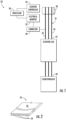
Figure 1 schematically illustrates selected portions of an elevator system. -
Figure 2 schematically illustrates a portion of an example suspension member. -
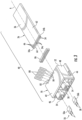
Figure 3 is an exploded view of a connector assembly used to connect to a suspension member. -
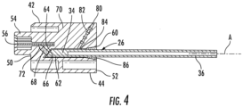
Figure 4 is a section view of the connector assembly ofFigure 3 when assembled. -
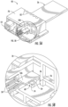
Figure 5A is a perspective view of the connector assembly ofFigure 4 , and which is partially cut-away to show a connection interface for a connection tab, contact pin, and cord/tension member. -
Figure 5B is an enlarged detail as identified inFigure 5A . -
Figure 6 is a perspective view of the connector assembly without showing a connector body. -
Figure 7 is a flowchart diagram of an example implementation of a method of using a connector assembly to establish electrically conductive connections with a plurality of tension members. - Embodiments of this disclosure provide a connector assembly that relies on contact pins contacting enlarged angular surfaces of tension members exposed at an end on a suspension member. This connection interface has increased contact area, is tolerant to a loose fit situation, reduces issues related to belt-to-connector tolerances, and is sealed to reduce environmental impacts on the connection.
-
Figure 1 schematically illustrates selected portions of anelevator system 20. Anelevator car 22 is supported by a roping arrangement orsuspension assembly 24 that includes a plurality ofsuspension members 26. Theelevator car 22 is coupled to acounterweight 28 by thesuspension members 26. Thesuspension members 26 move around asheave 38 as theelevator car 22 moves between landings or levels. - A suspension member monitoring device includes at least one
processor 30 that is configured to determine a condition of each of thesuspension members 26. Theprocessor 30 in the illustrated example includes a computing device and associated memory. Theprocessor 30 is programmed or otherwise configured to use different types of information indicative of the respective conditions of thesuspension members 26 and a combination of criteria to determine when it is desirable or necessary to remove any one of thesuspension members 26 from service. - An electric-based
monitor 32 uses an electrical inspection technique and generates or provides a corresponding indication regarding a condition of eachsuspension member 26. Theprocessor 30 receives the indication from the electric-basedmonitor 32. - In some example embodiments, the electric-based
monitor 32 is configured to apply electricity to at least one of the tension members, such as a steel cord, of eachsuspension member 26 and to detect or measure the electrical resistance of the tension member. Changes in the electrical resistance indicate changes in a condition of thesuspension member 26. Such resistance-based inspection techniques are known and need not be further described here. -
Figure 2 schematically illustrates a portion of anexample suspension member 26. In the illustrated embodiment, thesuspension member 26 is a flat belt including a plurality of cords ortension members 34 encased in ajacket 36 of a compressible material, such as polyurethane. In many embodiments, thetension members 34 comprise steel cords. Other embodiments include tension members that are made of different materials. The electrical inspection technique takes advantage of the electrically conductive nature of thetension members 34. - A
connector assembly 40 is used to connect the electric-basedmonitor 32 to an associated suspension member 26 (Figure 1 ). In one example, the electric-basedmonitor 32 wirelessly communicates the electrical resistance information to theprocessor 30. -
Figures 3-4 show one example of theconnector assembly 40. Theconnector assembly 40 includes a connector body that has afirst surface 42, asecond surface 44 facing opposite of thefirst surface 42, and first 46 and second 48 side surfaces connecting thefirst surface 42 to thesecond surface 44. Theconnector assembly 40 further includes aforward end wall 50 and arear end wall 52 facing opposite of theforward end wall 50. In one example, theforward end wall 50 includes one ormore ports 54 that each receive aconnection tab 56. Theconnection tab 56 includesprongs 58 that are used to connect to an associated connection interface for the electric-basedmonitor 32. In one example, therear end wall 52 includes an opening 60 (Figure 4 ) through which oneend 62 of thesuspension member 26 is inserted. - In one example, the
suspension member 26 extends along a center axis A with the plurality of cords/tension members 34 being arranged in a row and spaced apart from each other in a direction that extends across the axis A (Figure 3 ). The center axis A extends along a length of thesuspension member 26 with thetension members 34 being spaced apart from each other across a width of thesuspension member 26, the length being greater than the width. As best shown inFigure 4 , thesuspension member 26 has oneend 62 received within theopening 60 in therear end wall 52, wherein the oneend 62 has anend face 64 extending at an angle relative to the center axis A with ends of the plurality oftension members 34 being exposed. In one example, exposed end faces 66 of eachtension member 34 extend at the same angle as theend face 64 of thesuspension member 26. - In one example, the
end face 64 comprises a cut end face that is cut at a predetermined angle to provide increased contact area for the exposed end faces 66. Those skilled in the art who have the benefit of this description will be able to determine how to cut the end of the suspension member to achieve the desired angle. In one example, the predetermined angle is approximately a 45 degree angle relative to the center axis A. In one example, cutting ends of thetension members 34 at an angle provides the exposed end faces 66 with an elliptical or oval shape; however, other shapes could also be utilized to provide a desired contact area size/shape. - In one example, the
connector assembly 40 includes a plurality ofcontact members 68 that are supported within abody 70 of theconnector assembly 40. In one example, eachcontact member 68 contacts anexposed end face 66 of at least onetension member 34 to establish electrically conductive connections with the plurality oftension members 34. In one example, the plurality ofcontact members 68 are resiliently biased into engagement with exposed end faces 66 of the plurality oftension members 34. In one example, springs 72 are associated with thecontact members 68 as shown inFigure 4 . - In one example, there are at least two different types of
contact members 68. In one example, some of thecontact members 68 comprise output pins 74 that engageconnection tabs 56 as shown inFigures 5A-5B , whileother contact members 68 comprise bridgingpins 76 that connect the exposed end faces 66 of adjacent pairs oftension members 34 as shown inFigure 6 . In one example, theconnection tabs 56 comprise at least afirst connection tab 56a and asecond connection tab 56b, and the plurality oftension members 34 comprise afirst end cord 34a and asecond end cord 34b with a plurality ofadditional cords 34c between thefirst end cord 34a and thesecond end cord 34b as shown inFigure 3 . In one example, thefirst connection tab 56a contacts theoutput pin 74 associated with thefirst end cord 34a and thesecond connection tab 56b contacts theoutput pin 74 associated with thesecond end cord 34b as shown inFigures 5B and6 . This allows for the establishment electrically conductive connections with the plurality oftension members 34. - In one example, one or
more retention members 80 are used to prevent thesuspension member 26 from being removed from theconnector body 70 and to provide a mechanical load against the electrical contact pins 68. In one example, theconnector body 70 includes slots oropenings 82 that receive theretention members 80 such that theretention members 80 extend through theconnector body 70. - In one example, the retention members comprise a plurality of retention pins that extend at an angle relative to the center axis A and have
distal ends 84 that abut directly against an external surface of thejacket 36 as shown inFigure 6 . - As discussed above, the
connector body 70 includes anopening 60 that receives oneend 62 of thesuspension member 26 In one example, agasket 86 is installed within theconnector body 70. In one example, thegasket 86 completely surrounds thesuspension member 26 at theopening 62. This provides a sealed interface at this location and minimizes environmental degradation at a contact area between the exposed end faces 66 and thecontact members 68. - In one example, the
connection tabs 56 are received within theports 54 of theconnector body 70 and are orientated generally parallel to thesuspension member 26 and center axis A. In one example, the output pins 74 of thecontact members 68 extend at an angle relative to the center axis A to electrically connect the exposed end faces 66 of thetension members 34 and theconnection tabs 56. In one example, this angle is acute or obtuse to the center axis. In one example, the bridging pins 76 of thecontact members 68 also extend at an acute or obtuse angle relative to the center axis A. In one example, theretention members 80 extend at an acute or obtuse angle relative to the center axis A. -
Figure 7 is a flowchart diagram of an example implementation of a method of using aconnector assembly 40 to establish electrically conductive connections with a plurality oftension members 34. Atstep 100, the method includes encasing a plurality oftension members 34 in ajacket 36 to form asuspension member 26 that extends along a center axis A. Next, atstep 200, the method includes cutting oneend 62 of thesuspension member 26 at an angle relative to the center axis A to expose ends of the plurality oftension members 34. Atstep 300, the method includes inserting the oneend 62 of thesuspension member 26 into aconnector body 70. Finally, atstep 400, the method includes supporting a plurality ofcontact members 68 within theconnector body 70, eachcontact member 68 contacting anexposed end face 66 of onetension member 34 to establish electrically conductive connections with the plurality oftension members 34. - Additional steps can include inserting a plurality of retention pins 80 into the
connector body 70 to engage an external surface of thejacket 36 to prevent thesuspension member 26 from being removed from theconnector body 70, and/or forming anopening 60 in theconnector body 70, inserting the oneend 62 of thesuspension member 26 into theopening 60, and installing agasket 86 to surround thesuspension member 26 at theopening 60. - The subject disclosure provides a connector assembly that is compatible with existing Resistance Belt Inspection (RBI) systems. The interface to the RBI module remains unchanged; however, the interface to the suspension member relies on contact pins contacting an enlarged angular surface at the end of the suspension member. In one example, the suspension member is prepared with angular cut, e.g. approximately a 45° cut. By cutting the suspension member at an angle, a larger conic shaped area of the cord/tension member will be exposed, thereby reducing the required precision of the connector. Angled, spring-loaded contact pins contact the exposed belt cords of the suspension member. The subject disclosure utilizes two types of contact pins, including bridging pins to connect adjacent cord pairs and output pins to connect to the connection tabs. This connection interface of the subject disclosure has increased contact area, is tolerant to a loose fit circumstance, reduces issues related to belt-to-connector tolerances, and is sealed to reduce environmental impacts on the connection.
- The preceding description is exemplary rather than limiting in nature. Variations and modifications to the disclosed examples may become apparent to those skilled in the art that do not necessarily depart from the essence of this invention. The scope of legal protection given to this invention can only be determined by studying the following claims.
Claims (15)
- A connector assembly comprising:a connector body;a suspension member extending along a center axis and comprising a plurality of tension members encased in a jacket, the suspension member having one end received within the connector body, and wherein the one end has an end face extending at an angle relative to the center axis with ends of the plurality of tension members being exposed; anda plurality of contact members supported within the connector body, wherein each contact member contacts an exposed end face of at least one tension member to establish electrically conductive connections with the plurality of tension members.
- The connector assembly of claim 1, including at least one retention member extending through the connector body to prevent the suspension member from being removed from the connector body.
- The connector assembly of claim 2, wherein the at least one retention member comprises a plurality of retention pins that extend at an angle relative to the center axis and have distal ends that abut against an external surface of the jacket.
- The connector assembly of any of claims 1 to 3, wherein the center axis extends along a length of the suspension member, and the plurality of tension members comprise a plurality of cords that are spaced apart from each other across a width of the suspension member, and wherein exposed end faces of each cord have an elliptical shape.
- The connector assembly of any of claims 1 to 4, wherein an end face of the suspension member extends at approximately a 45 degree angle relative to the center axis.
- The connector assembly of any of claims 1 to 5, wherein the connector body includes an opening to receive the one end of the suspension member, and including a gasket that surrounds the suspension member at the opening.
- The connector assembly of any of claims 1 to 6, wherein the plurality of contact members comprise bridging pins that connect exposed end faces of adjacent pairs of tension members and output pins that engage connection tabs.
- The connector assembly of claim 7, wherein the connection tabs comprise at least a first connection tab and a second connection tab, and wherein the plurality of tension members comprise a first end cord and a second end cord with a plurality of additional cords between the first end cord and the second end cord, and wherein the first connection tab contacts at least one output pin associated with the first end cord and the second connection tab contacts at least one output pin associated with the second end cord.
- The connector assembly of any of claims 1 to 8, wherein the plurality of contact members are resiliently biased into engagement with exposed end faces of the plurality of tension members.
- The connector assembly of any of claims 1 to 9, including at least one connection tab received within the connector body, and wherein at least one contact member of the plurality of contact members extends at an angle relative to the center axis to electrically connect the exposed end face of at least one tension member and the at least one connection tab.
- An elevator system, comprising:an elevator car; anda connector assembly according to any of claims 1 to 10.
- The elevator system of claim 11, wherein:at least one suspension member supports the elevator car and facilitates movement of the elevator car, wherein the at least one suspension member extends along a center axis and comprising a plurality of tension members encased in a jacket;a connector receives one end of the at least one suspension member, wherein the one end has a cut end face extending at an angle relative to the center axis with ends of the plurality of tension members being exposed at the cut end face; anda plurality of contact members are supported within the connector, wherein each contact member contacts an exposed end face of at least one tension member to establish electrically conductive connections with the plurality of tension members.
- A method comprising:encasing a plurality of tension members in a jacket to form a suspension member that extends along a center axis;cutting one end of the suspension member at an angle relative to the center axis to expose ends of the plurality of tension members;inserting the one end of a suspension member into a connector body; andsupporting a plurality of contact members within the connector body, each contact member contacting an exposed end face of at least one tension member to establish electrically conductive connections with the plurality of tension members.
- The method of claim 13, including inserting a plurality of retention pins into the connector body to engage an external surface of the jacket to prevent the suspension member from being removed from the connector body.
- The method of claim 13 or 14, including forming an opening in the connector body, inserting the one end of the suspension member into the opening, and installing a gasket to surround the suspension member at the opening.
Applications Claiming Priority (1)
| Application Number | Priority Date | Filing Date | Title |
|---|---|---|---|
| US18/228,737 US12091287B1 (en) | 2023-08-01 | 2023-08-01 | Elevator connector with angled interface |
Publications (2)
| Publication Number | Publication Date |
|---|---|
| EP4501834A1 true EP4501834A1 (en) | 2025-02-05 |
| EP4501834B1 EP4501834B1 (en) | 2026-04-22 |
Family
ID=92108655
Family Applications (1)
| Application Number | Title | Priority Date | Filing Date |
|---|---|---|---|
| EP24191477.9A Active EP4501834B1 (en) | 2023-08-01 | 2024-07-29 | Elevator connector with angled interface |
Country Status (3)
| Country | Link |
|---|---|
| US (2) | US12091287B1 (en) |
| EP (1) | EP4501834B1 (en) |
| CN (1) | CN119429900A (en) |
Families Citing this family (3)
| Publication number | Priority date | Publication date | Assignee | Title |
|---|---|---|---|---|
| US11976651B2 (en) * | 2020-11-10 | 2024-05-07 | Bill Spitzer & Associates | Reciprocating pump packing lubricator |
| US12415706B2 (en) * | 2021-01-29 | 2025-09-16 | Tk Elevator Innovation And Operations Gmbh | Electrical monitoring connector for an elevator hoisting member |
| US12091287B1 (en) * | 2023-08-01 | 2024-09-17 | Otis Elevator Company | Elevator connector with angled interface |
Citations (2)
| Publication number | Priority date | Publication date | Assignee | Title |
|---|---|---|---|---|
| JP5378426B2 (en) * | 2011-01-25 | 2013-12-25 | 株式会社日立製作所 | Elevator device and rope inspection device |
| US20210331897A1 (en) * | 2020-04-24 | 2021-10-28 | Thyssenkrupp Elevator Innovation And Operations Gmbh | Belt end termination for a belt comprising a plurality of load carriers |
Family Cites Families (26)
| Publication number | Priority date | Publication date | Assignee | Title |
|---|---|---|---|---|
| CH559433A5 (en) * | 1972-11-28 | 1975-02-28 | Sprecher & Schuh Ag | |
| EP1730067B1 (en) * | 2004-03-16 | 2011-02-09 | Otis Elevator Company | Electrical connector device for use with elevator load bearing members |
| CN1926047B (en) * | 2004-03-16 | 2010-06-23 | 奥蒂斯电梯公司 | Electrical connectors and restraints for elevator belts |
| ES2360527T3 (en) * | 2004-03-16 | 2011-06-06 | Otis Elevator Company | ELECTRICAL CONNECTOR DEVICE FOR USE WITH ELEVATOR LOAD SUPPORT MEMBERS. |
| BRPI0922055A2 (en) * | 2008-11-19 | 2015-12-22 | Inventio Ag | elevator installation support belt. |
| CN102471025B (en) * | 2009-07-06 | 2014-06-25 | 因温特奥股份公司 | contact device |
| EP2534082B1 (en) * | 2010-02-10 | 2018-06-27 | Otis Elevator Company | Elevator system belt having connecting devices attached thereto |
| DE102011055168A1 (en) * | 2011-11-09 | 2013-05-16 | Contitech Transportbandsysteme Gmbh | Belt or belt segment with open end |
| CA2855888C (en) * | 2011-12-16 | 2020-09-29 | Inventio Ag | System for electrical contacting of tensile carriers in support means |
| US9245985B2 (en) | 2012-03-28 | 2016-01-26 | Infineon Technologies Americas Corp. | IGBT with buried emitter electrode |
| US9995711B2 (en) * | 2012-04-02 | 2018-06-12 | Otis Elevator Company | Calibration of wear detection system |
| FI124543B (en) * | 2012-12-30 | 2014-10-15 | Kone Corp | Linen mount and lift |
| EP3028979A1 (en) * | 2014-12-01 | 2016-06-08 | KONE Corporation | Method for manufacturing an electrical contact arrangement and arrangement |
| EP3053867A1 (en) * | 2015-02-03 | 2016-08-10 | KONE Corporation | Rope terminal arrangement, arrangement for condition monitoring of an elevator rope and elevator |
| EP3163119A1 (en) * | 2015-10-29 | 2017-05-03 | KONE Corporation | Method, rope arrangement and elevator |
| US10183841B2 (en) * | 2016-12-12 | 2019-01-22 | Thyssenkrup Elevator Ag | Multi-wedge end termination for an elevator system |
| EP3577474B1 (en) * | 2017-01-31 | 2024-05-01 | Inventio Ag | Suspension member arrangement for an elevator and monitoring arrangement for monitoring a suspension member |
| WO2019052909A1 (en) * | 2017-09-15 | 2019-03-21 | Inventio Ag | METHOD FOR ELECTRICALLY CONNECTING A CONNECTION ELEMENT TO A STRAP FOR AN ELEVATOR AND CORRESPONDING BELT ASSEMBLY |
| US11174126B2 (en) * | 2017-11-28 | 2021-11-16 | Inventio Ag | Connection element for electrically contacting tension members in a load-bearing belt for an elevator system, and method for assembling the connection element on the belt |
| US20210130134A1 (en) * | 2019-10-30 | 2021-05-06 | Thyssenkrupp Elevator Innovation And Operations Gmbh | Methods of treating a load-bearing part in a passenger moving system |
| US12415706B2 (en) * | 2021-01-29 | 2025-09-16 | Tk Elevator Innovation And Operations Gmbh | Electrical monitoring connector for an elevator hoisting member |
| US11999594B2 (en) * | 2021-08-24 | 2024-06-04 | Weidmüller Interface GmbH & Co. KG | Elevator belt monitoring system |
| US11634302B2 (en) * | 2021-09-03 | 2023-04-25 | Weidmüller Interface GmbH & Co. KG | Elevator belt monitoring apparatus and blade contact |
| US12570501B2 (en) * | 2022-02-25 | 2026-03-10 | Tk Elevator Innovation And Operations Gmbh | Condition monitoring system for elevator hoisting members |
| US20250019206A1 (en) * | 2023-07-14 | 2025-01-16 | Otis Elevator Company | Elevator connector with alignment feature |
| US12091287B1 (en) * | 2023-08-01 | 2024-09-17 | Otis Elevator Company | Elevator connector with angled interface |
-
2023
- 2023-08-01 US US18/228,737 patent/US12091287B1/en active Active
-
2024
- 2024-06-19 US US18/747,601 patent/US12286330B2/en active Active
- 2024-07-02 CN CN202410876224.2A patent/CN119429900A/en active Pending
- 2024-07-29 EP EP24191477.9A patent/EP4501834B1/en active Active
Patent Citations (2)
| Publication number | Priority date | Publication date | Assignee | Title |
|---|---|---|---|---|
| JP5378426B2 (en) * | 2011-01-25 | 2013-12-25 | 株式会社日立製作所 | Elevator device and rope inspection device |
| US20210331897A1 (en) * | 2020-04-24 | 2021-10-28 | Thyssenkrupp Elevator Innovation And Operations Gmbh | Belt end termination for a belt comprising a plurality of load carriers |
Also Published As
| Publication number | Publication date |
|---|---|
| US12091287B1 (en) | 2024-09-17 |
| CN119429900A (en) | 2025-02-14 |
| US20250042695A1 (en) | 2025-02-06 |
| EP4501834B1 (en) | 2026-04-22 |
| US12286330B2 (en) | 2025-04-29 |
Similar Documents
| Publication | Publication Date | Title |
|---|---|---|
| US12091287B1 (en) | Elevator connector with angled interface | |
| US8424653B2 (en) | Electrical signal application strategies for monitoring a condition of an elevator load bearing member | |
| JP5514328B2 (en) | Elevator system belt with connecting device | |
| EP1730065B1 (en) | Electrical connector and restraining device for use with elevator belts | |
| US8991562B2 (en) | Electrical contacting device for elevator support tensile carriers | |
| JP3174115U (en) | Electrical connector penetrating conductive member | |
| EP3107855B1 (en) | Connector for inspection system of elevator tension member | |
| US12415706B2 (en) | Electrical monitoring connector for an elevator hoisting member | |
| WO2018141554A1 (en) | Suspension member arrangement for an elevator and monitoring arrangement for monitoring a suspension member | |
| CN110235007A (en) | Suspension member arrangement for an elevator and monitoring device for monitoring a suspension member | |
| EP4491560A1 (en) | Elevator connector with alignment feature | |
| CN114988250A (en) | Detection device and detection method for traction member, and elevator system | |
| EP4737375A1 (en) | Resistance-based inspection of elevator system support members | |
| US20250243037A1 (en) | Electrical Connector | |
| CA3048752C (en) | Suspension member arrangement for an elevator and monitoring arrangement for monitoring a suspension member | |
| HK1178506B (en) | Assembly comprising a belt and connecting devices and method of mounting a connecting device to a belt |
Legal Events
| Date | Code | Title | Description |
|---|---|---|---|
| PUAI | Public reference made under article 153(3) epc to a published international application that has entered the european phase |
Free format text: ORIGINAL CODE: 0009012 |
|
| STAA | Information on the status of an ep patent application or granted ep patent |
Free format text: STATUS: THE APPLICATION HAS BEEN PUBLISHED |
|
| AK | Designated contracting states |
Kind code of ref document: A1 Designated state(s): AL AT BE BG CH CY CZ DE DK EE ES FI FR GB GR HR HU IE IS IT LI LT LU LV MC ME MK MT NL NO PL PT RO RS SE SI SK SM TR |
|
| STAA | Information on the status of an ep patent application or granted ep patent |
Free format text: STATUS: REQUEST FOR EXAMINATION WAS MADE |
|
| 17P | Request for examination filed |
Effective date: 20250711 |
|
| GRAP | Despatch of communication of intention to grant a patent |
Free format text: ORIGINAL CODE: EPIDOSNIGR1 |
|
| STAA | Information on the status of an ep patent application or granted ep patent |
Free format text: STATUS: GRANT OF PATENT IS INTENDED |
|
| INTG | Intention to grant announced |
Effective date: 20251210 |
|
| GRAS | Grant fee paid |
Free format text: ORIGINAL CODE: EPIDOSNIGR3 |
|
| GRAA | (expected) grant |
Free format text: ORIGINAL CODE: 0009210 |
|
| STAA | Information on the status of an ep patent application or granted ep patent |
Free format text: STATUS: THE PATENT HAS BEEN GRANTED |
|
| AK | Designated contracting states |
Kind code of ref document: B1 Designated state(s): AL AT BE BG CH CY CZ DE DK EE ES FI FR GB GR HR HU IE IS IT LI LT LU LV MC ME MK MT NL NO PL PT RO RS SE SI SK SM TR |
|
| REG | Reference to a national code |
Ref country code: CH Ref legal event code: F10 Free format text: ST27 STATUS EVENT CODE: U-0-0-F10-F00 (AS PROVIDED BY THE NATIONAL OFFICE) Effective date: 20260422 Ref country code: GB Ref legal event code: FG4D |
|
| REG | Reference to a national code |
Ref country code: DE Ref legal event code: R096 Ref document number: 602024004134 Country of ref document: DE |