EP4501784A2 - AIRCRAFT SEATING ARRANGEMENT - Google Patents
AIRCRAFT SEATING ARRANGEMENT Download PDFInfo
- Publication number
- EP4501784A2 EP4501784A2 EP24220561.5A EP24220561A EP4501784A2 EP 4501784 A2 EP4501784 A2 EP 4501784A2 EP 24220561 A EP24220561 A EP 24220561A EP 4501784 A2 EP4501784 A2 EP 4501784A2
- Authority
- EP
- European Patent Office
- Prior art keywords
- mounts
- seating assembly
- seat pan
- aircraft seating
- engagement portion
- Prior art date
- Legal status (The legal status is an assumption and is not a legal conclusion. Google has not performed a legal analysis and makes no representation as to the accuracy of the status listed.)
- Pending
Links
Images















Classifications
-
- B—PERFORMING OPERATIONS; TRANSPORTING
- B64—AIRCRAFT; AVIATION; COSMONAUTICS
- B64D—EQUIPMENT FOR FITTING IN OR TO AIRCRAFT; FLIGHT SUITS; PARACHUTES; ARRANGEMENT OR MOUNTING OF POWER PLANTS OR PROPULSION TRANSMISSIONS IN AIRCRAFT
- B64D11/00—Passenger or crew accommodation; Flight-deck installations not otherwise provided for
- B64D11/06—Arrangements of seats, or adaptations or details specially adapted for aircraft seats
- B64D11/0639—Arrangements of seats, or adaptations or details specially adapted for aircraft seats with features for adjustment or converting of seats
-
- B—PERFORMING OPERATIONS; TRANSPORTING
- B64—AIRCRAFT; AVIATION; COSMONAUTICS
- B64D—EQUIPMENT FOR FITTING IN OR TO AIRCRAFT; FLIGHT SUITS; PARACHUTES; ARRANGEMENT OR MOUNTING OF POWER PLANTS OR PROPULSION TRANSMISSIONS IN AIRCRAFT
- B64D11/00—Passenger or crew accommodation; Flight-deck installations not otherwise provided for
- B64D11/06—Arrangements of seats, or adaptations or details specially adapted for aircraft seats
- B64D11/0639—Arrangements of seats, or adaptations or details specially adapted for aircraft seats with features for adjustment or converting of seats
- B64D11/064—Adjustable inclination or position of seats
-
- B—PERFORMING OPERATIONS; TRANSPORTING
- B60—VEHICLES IN GENERAL
- B60N—SEATS SPECIALLY ADAPTED FOR VEHICLES; VEHICLE PASSENGER ACCOMMODATION NOT OTHERWISE PROVIDED FOR
- B60N2/00—Seats specially adapted for vehicles; Arrangement or mounting of seats in vehicles
- B60N2/02—Seats specially adapted for vehicles; Arrangement or mounting of seats in vehicles the seat or part thereof being movable, e.g. adjustable
- B60N2/22—Seats specially adapted for vehicles; Arrangement or mounting of seats in vehicles the seat or part thereof being movable, e.g. adjustable the back-rest being adjustable
- B60N2/23—Seats specially adapted for vehicles; Arrangement or mounting of seats in vehicles the seat or part thereof being movable, e.g. adjustable the back-rest being adjustable by linear actuators, e.g. linear screw mechanisms
-
- B—PERFORMING OPERATIONS; TRANSPORTING
- B60—VEHICLES IN GENERAL
- B60N—SEATS SPECIALLY ADAPTED FOR VEHICLES; VEHICLE PASSENGER ACCOMMODATION NOT OTHERWISE PROVIDED FOR
- B60N2/00—Seats specially adapted for vehicles; Arrangement or mounting of seats in vehicles
- B60N2/64—Back-rests or cushions
- B60N2/646—Back-rests or cushions shape of the cushion
-
- B—PERFORMING OPERATIONS; TRANSPORTING
- B60—VEHICLES IN GENERAL
- B60N—SEATS SPECIALLY ADAPTED FOR VEHICLES; VEHICLE PASSENGER ACCOMMODATION NOT OTHERWISE PROVIDED FOR
- B60N2/00—Seats specially adapted for vehicles; Arrangement or mounting of seats in vehicles
- B60N2/68—Seat frames
- B60N2/682—Joining means
-
- B—PERFORMING OPERATIONS; TRANSPORTING
- B60—VEHICLES IN GENERAL
- B60N—SEATS SPECIALLY ADAPTED FOR VEHICLES; VEHICLE PASSENGER ACCOMMODATION NOT OTHERWISE PROVIDED FOR
- B60N2/00—Seats specially adapted for vehicles; Arrangement or mounting of seats in vehicles
- B60N2/68—Seat frames
- B60N2/686—Panel like structures
-
- B—PERFORMING OPERATIONS; TRANSPORTING
- B60—VEHICLES IN GENERAL
- B60N—SEATS SPECIALLY ADAPTED FOR VEHICLES; VEHICLE PASSENGER ACCOMMODATION NOT OTHERWISE PROVIDED FOR
- B60N2/00—Seats specially adapted for vehicles; Arrangement or mounting of seats in vehicles
- B60N2/70—Upholstery springs ; Upholstery
- B60N2/7005—Upholstery springs ; Upholstery detachable
-
- B—PERFORMING OPERATIONS; TRANSPORTING
- B60—VEHICLES IN GENERAL
- B60N—SEATS SPECIALLY ADAPTED FOR VEHICLES; VEHICLE PASSENGER ACCOMMODATION NOT OTHERWISE PROVIDED FOR
- B60N2/00—Seats specially adapted for vehicles; Arrangement or mounting of seats in vehicles
- B60N2/75—Arm-rests
- B60N2/753—Arm-rests movable to an inoperative position
-
- B—PERFORMING OPERATIONS; TRANSPORTING
- B60—VEHICLES IN GENERAL
- B60N—SEATS SPECIALLY ADAPTED FOR VEHICLES; VEHICLE PASSENGER ACCOMMODATION NOT OTHERWISE PROVIDED FOR
- B60N3/00—Arrangements or adaptations of other passenger fittings, not otherwise provided for
- B60N3/001—Arrangements or adaptations of other passenger fittings, not otherwise provided for of tables or trays
- B60N3/002—Arrangements or adaptations of other passenger fittings, not otherwise provided for of tables or trays of trays
- B60N3/004—Arrangements or adaptations of other passenger fittings, not otherwise provided for of tables or trays of trays of foldable trays mounted on the back-rest
-
- B—PERFORMING OPERATIONS; TRANSPORTING
- B60—VEHICLES IN GENERAL
- B60N—SEATS SPECIALLY ADAPTED FOR VEHICLES; VEHICLE PASSENGER ACCOMMODATION NOT OTHERWISE PROVIDED FOR
- B60N3/00—Arrangements or adaptations of other passenger fittings, not otherwise provided for
- B60N3/10—Arrangements or adaptations of other passenger fittings, not otherwise provided for of receptacles for food or beverages, e.g. refrigerated
- B60N3/101—Arrangements or adaptations of other passenger fittings, not otherwise provided for of receptacles for food or beverages, e.g. refrigerated fixed
-
- B—PERFORMING OPERATIONS; TRANSPORTING
- B64—AIRCRAFT; AVIATION; COSMONAUTICS
- B64D—EQUIPMENT FOR FITTING IN OR TO AIRCRAFT; FLIGHT SUITS; PARACHUTES; ARRANGEMENT OR MOUNTING OF POWER PLANTS OR PROPULSION TRANSMISSIONS IN AIRCRAFT
- B64D11/00—Passenger or crew accommodation; Flight-deck installations not otherwise provided for
- B64D11/06—Arrangements of seats, or adaptations or details specially adapted for aircraft seats
-
- B—PERFORMING OPERATIONS; TRANSPORTING
- B64—AIRCRAFT; AVIATION; COSMONAUTICS
- B64D—EQUIPMENT FOR FITTING IN OR TO AIRCRAFT; FLIGHT SUITS; PARACHUTES; ARRANGEMENT OR MOUNTING OF POWER PLANTS OR PROPULSION TRANSMISSIONS IN AIRCRAFT
- B64D11/00—Passenger or crew accommodation; Flight-deck installations not otherwise provided for
- B64D11/06—Arrangements of seats, or adaptations or details specially adapted for aircraft seats
- B64D11/0624—Arrangements of electrical connectors, e.g. for earphone, internet or electric supply
-
- B—PERFORMING OPERATIONS; TRANSPORTING
- B64—AIRCRAFT; AVIATION; COSMONAUTICS
- B64D—EQUIPMENT FOR FITTING IN OR TO AIRCRAFT; FLIGHT SUITS; PARACHUTES; ARRANGEMENT OR MOUNTING OF POWER PLANTS OR PROPULSION TRANSMISSIONS IN AIRCRAFT
- B64D11/00—Passenger or crew accommodation; Flight-deck installations not otherwise provided for
- B64D11/06—Arrangements of seats, or adaptations or details specially adapted for aircraft seats
- B64D11/0647—Seats characterised by special upholstery or cushioning features
-
- B—PERFORMING OPERATIONS; TRANSPORTING
- B64—AIRCRAFT; AVIATION; COSMONAUTICS
- B64D—EQUIPMENT FOR FITTING IN OR TO AIRCRAFT; FLIGHT SUITS; PARACHUTES; ARRANGEMENT OR MOUNTING OF POWER PLANTS OR PROPULSION TRANSMISSIONS IN AIRCRAFT
- B64D11/00—Passenger or crew accommodation; Flight-deck installations not otherwise provided for
- B64D11/06—Arrangements of seats, or adaptations or details specially adapted for aircraft seats
- B64D11/0648—Lower frame constructions
-
- B—PERFORMING OPERATIONS; TRANSPORTING
- B64—AIRCRAFT; AVIATION; COSMONAUTICS
- B64D—EQUIPMENT FOR FITTING IN OR TO AIRCRAFT; FLIGHT SUITS; PARACHUTES; ARRANGEMENT OR MOUNTING OF POWER PLANTS OR PROPULSION TRANSMISSIONS IN AIRCRAFT
- B64D11/00—Passenger or crew accommodation; Flight-deck installations not otherwise provided for
- B64D11/06—Arrangements of seats, or adaptations or details specially adapted for aircraft seats
- B64D11/0649—Seats characterised by special features for reducing weight
-
- B—PERFORMING OPERATIONS; TRANSPORTING
- B60—VEHICLES IN GENERAL
- B60N—SEATS SPECIALLY ADAPTED FOR VEHICLES; VEHICLE PASSENGER ACCOMMODATION NOT OTHERWISE PROVIDED FOR
- B60N2205/00—General mechanical or structural details
- B60N2205/20—Measures for elimination or compensation of play or backlash
Definitions
- the embodiments described herein relate generally to seat devices, systems, and methods. In particular, some embodiments described herein relate to aircraft seat devices, systems, and methods.
- aircraft seating assemblies typically are configured as 2, 3 or 4 seat units. These aircraft seating assemblies have a structure for withstanding forces caused not only due to acceleration and deceleration of the aircraft during normal operation, but also substantial forces caused during emergencies. Significantly, the aircraft seats desirably achieve this performance while being relatively lightweight. Further, while the structural integrity and weight of the seating assemblies is important, the cost of the assemblies is also an important consideration.
- Embodiments of an aircraft seating assembly are disclosed which are both compliant with industry regulations and lightweight yet capable of withstanding significant forces.
- the aircraft seating assembly can be installed in an aircraft.
- the assembly can include a seat pan, a connection frame, and one or more mounts.
- the one or more mounts can removably couple the seat pan to the connection frame.
- the one or more mounts can be attached to a bottom portion of the seat pan.
- the aircraft seating assembly can include a back support.
- the back support can include a back support frame and a cushioning member.
- the cushioning member can be removably coupled to the back support frame.
- the aircraft seating assembly can include a connection frame, a back support, and a tilt system.
- the back support can be coupled to the connection frame.
- the tilt system can be coupled to the back support and to the connection frame.
- the tilt system can allow the back support to articulate relative to a connection frame.
- the tilt system can include a pivot member and an actuator.
- the actuator can include a first end and a second end.
- the actuator can be coupled to the connection frame at the first end and the pivot member at the second end.
- the actuator can be centrally located relative to a width of a seat of the aircraft seating assembly.
- the aircraft seating assembly can include a connection frame, a back support, and a tilt system.
- the back support can be coupled to the connection frame.
- the tilt system can be coupled to the back support and to the connection frame.
- the tilt system can allow the back support to articulate relative to a connection frame.
- the tilt system can include a pivot member, a carrier and an actuator.
- the carrier can be coupled to the connection frame.
- the actuator can be positioned within the carrier and can be coupled to the pivot member.
- the aircraft seating assembly can include a back support and a retention system.
- the retention system can be coupled to the back support.
- the retention system can retain an object in place when in a closed configuration.
- the retention system can include a base member, a clamp member and a biasing component.
- the clamp member can be rotatably coupled to the base portion.
- the biasing component can bias the clamp member into the closed configuration.
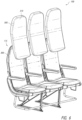
- the aircraft seating assembly 100 can include three seats 105a, 105b, 105c each of which defines a seating position for one passenger and, typically, for an adult passenger. However, it should be understood that the aircraft seating assembly 100 may be expanded to include additional seats or reduced to include fewer seats. In some embodiments, the aircraft seating assembly 100 can include four seats. In some embodiments, the aircraft seating assembly 100 can include a single seat or two seats. Since the seats 105a, 105b, 105c are similar in design and construction, only seat 105a will be described in detail; however, it should be understood that the same, or similar, structures and features can be utilized for seats 105b, 105c.
- the first seat 105a can include a seat pan 110, a back support 115, a connection frame 120, and an armrest 125.
- the aircraft seating assembly 100 is designed to be placed within the cabin of an aircraft and attached to the cabin via the connection frame 120.
- the seat pan 110 can be connected to the connection frame 120. As shown in the illustrated embodiment of Figure 2 , in some embodiments the seat pan 110 can be removably coupled to one or more tubes 121 of the connection frame 120, such as a fore tube positioned nearer a front portion 111 of the seat pan 110 and an aft tube positioned nearer a rear portion 114 of the seat pan 110. These tubes 121 can extend along the width of the aircraft seating assembly 100.
- the seat pan 110 can be removably coupled to these tubes 121 with one or more mounts 200. In the illustrated embodiment, four mounts 200 are attached to a bottom of the seat pan 110 and are attached at four, spaced apart corners of the seat pan 110.
- the mounts 200 can advantageously be arranged to allow the seat pan 110 to more easily flex along portions which are spaced from the mounting points of the mounts 200. This greater ability for the seat pan 110 to flex can allow for a more compliant seat pan 110 thereby enhancing comfort for the passenger.
- the mounts 200 can be generally located under the passenger's thighs and buttock to provide substantial support for the passenger. In some embodiments, fewer or greater number of mounts 200 can be used to removably attach the seat pan to the connection frame 120 and/or the mounts 200 can be positioned at other locations relative to the seat pan 110 as desired.
- the seat pan 110 can include features which significantly enhance passenger comfort.
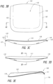
- the seat pan 110 can include a waterfall feature along a front portion 111 of the seat pan 110 and/or along one or both side portions 112 of the seat pan 110.
- the seat pan 110 can have an upward slope from the rear portion 114 of the seat pan 110 towards the front portion 111 of the seat pan 110. Proximate an edge of the front portion 111, the seat pan 110 can slope towards the floor of the aircraft.
- the edge of the front portion 111 of the seat pan 110 can have an angle of about 1 to about 45 degrees relative to a plane 116 perpendicular to the aircraft floor, an angle of about 5 to about 30 degrees relative to the plane 116, an angle of about 10 to about 15 degrees relative to the plane 116, any sub-range within these ranges, and/or any other angle as desired.
- the transition from the upward slope to the downward slope can be gradual and can include a generally rounded surface 118.
- the seat pan 110 can have an upward slope from the central portion 113 of the seat pan 110 towards one or both side portions 112 of the seat pan 110. Proximate an edge of one or both the side portions 112, the seat pan 110 can slope towards the floor of the aircraft. As shown in the illustrated embodiment, the edge of one or both sides portions 112 of the seat pan 110 can have an angle of about 1 to about 45 degrees relative to a plane 117 perpendicular to the aircraft floor, an angle of about 5 to about 30 degrees relative to the plane 117, an angle of about 10 to about 15 degrees relative to the plane 117, any sub-range within these ranges, and/or any other angle as desired.
- the transition from the upward slope to the downward slope can be gradual and can include a generally rounded surface 119.
- the front portion 111 and/or one or both side portions 112 can be angled towards the floor of the aircraft.
- the waterfall feature can advantageously enhance passenger comfort by reducing pressure points on a passenger's legs while the passenger is seated.
- the seat pan 110 can be relatively flexible to allow for a greater degree of compliancy. This greater flexibility can significantly enhance passenger comfort while the passenger is seated.
- the mounts 200 can allow the seat pan 110 to articulate.
- the seat pan 110 can rotate and/or translate relative to the connection frame 120.
- the mounts 200 can allow the seat pan 110 to be rotated from a first configuration 110a as shown in Figure 4A , such as a fully attached configuration, to a second configuration 110b as shown in Figure 4B , such as a maintenance configuration, without having to completely detach the seat pan 110 from the connection assembly 120.
- a first configuration 110a as shown in Figure 4A such as a fully attached configuration
- a second configuration 110b such as a maintenance configuration
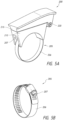
- the mounts 200 can include a strap 205 which can releasably couple the mount 200 to the connection frame 120.
- the strap 205 can be formed from a material having some degree of compliancy such that the strap can be loosened.
- the strap 205 can include a flexible, elongate member 206 with a coupling member 207.
- the coupling member 207 can be used to lock the elongate member 206 in a desired position and/or apply tension to the elongate member 206.
- the coupling member 207 can be a worm gear or similar device.
- This strap-style mount 200 advantageously does not require holes to be drilled along the tube 121 to secure the mount 200 to the connection frame 120. This can be particularly beneficial as such drilling can decrease the strength of the 121. Moreover, as the strap-style mount 200 can be removably coupled to the connection frame 120 without drilling holes, the strap-style mount 200 provides greater flexibility in choosing where to position the seat along the width of the aircraft seating assembly 100. In some embodiments, interior and/or exterior surfaces of the elongate member 206 can be provided with an interior lining to reduce the likelihood of damage to components to which the elongate member 206 is in contact, such as tube 121.
- the mounts 200 can include a first member 210 and a second member 215.
- the first and second members 210, 215 can be movable relative to each other.
- the first and second members 210, 215 can be rotatably coupled via a hinge 220.
- the first and second members 210, 215 can be translatably coupled to each other in addition to, or in lieu of, being rotatably coupled.
- the first member 210 can be attached to the connection frame 120 and the second member 215 can be attached to the seat pan 110. Such a design can allow the seat pan 110 to be rotatable as shown in Figure 4 .
- mounts 900, 950 are illustrated which can be used to connect the seat pan 110 to the connection frame 120, such as the tubes 121.
- the mounts 900, 950 can share the same, or similar, structures and features to mounts 200.
- the seat pan 110 can be removably coupled to one or more tubes 121 of the connection frame 120, such as a fore tube positioned nearer a front portion 111 of the seat pan 110 and an aft tube positioned nearer a rear portion 114 of the seat pan 110. These tubes 121 can extend along the width of the aircraft seating assembly 100.
- the seat pan 110 can be removably coupled to these tubes 121 with one or more mounts 900, 950.
- two mounts 900 and two mounts 950 are attached to a bottom of the seat pan 110 and are attached at four, spaced apart corners of the seat pan 110, with the mounts 900 being positioned nearer a rear portion 114 of the seat pan 110 and the mounts 950 being positioned nearer a front portion 111 of the seat pan 110.
- the mounts 900 and the mounts 950 can be positioned at any position on the seat pan 110 including the reverse of the configuration described above.
- the mounts 900, 950 can advantageously be arranged to allow the seat pan 110 to more easily flex along portions which are spaced from the mounting points of the mounts 900, 950. This greater ability for the seat pan 110 to flex can allow for a more compliant seat pan 110 thereby enhancing comfort for the passenger.
- the mounts 900, 950 can be generally located under the passenger's thighs and buttock to provide substantial support for the passenger. In some embodiments, fewer or greater number of mounts 900, 950 can be used to removably attach the seat pan to the connection frame 120.
- the mounts 900, 950 can include straps 905, 955 which can releasably couple the mounts 900, 950 to the connection frame 120. Straps 905, 955 can be formed from a material having some degree of compliancy such that the strap can be loosened. As shown in Figures 56 and 57 , the straps 905, 955 can include flexible, elongate members 906, 956 with coupling members 907, 957. These can be similar to elongate member 206 and coupling member 207 described above.
- the coupling members 907, 957 can be used to lock the elongate members 906, 956 in a desired position and/or apply tension to the elongate members 906, 956.
- the coupling members 907, 957 can be a worm gear or similar device.
- These strap-style mounts 900, 950 advantageously do not require holes to be drilled along the tube 121 to secure the mounts 900, 950 to the connection frame 120.
- interior and/or exterior surfaces of the elongate members 906, 956 can be provided with an interior lining to reduce the likelihood of damage to components to which the elongate members 906, 956 are in contact, such as tube 121.
- the elongate members 906, 956 and/or coupling members 907, 957 can have different constructions.
- the mounts 900, 950 can allow the seat pan 110 to be rotated relative to the tubes 121 of the connection assembly 120.
- the seat pan 110 is rotated clockwise about a fore tube 121.
- portions of the mounts 900, 950 can retained on the tubes 121 while other portions of the mounts 900, 950 can be disengaged.
- engagement and disengagement can be via a "quick disconnect" coupling mechanism, such as a snap-fit coupling, thereby facilitating removal.
- this arrangement can be reversed.
- the seat pan 110 can be rotated in a counter-clockwise direction along an aft tube 121.
- the mount 900 can include a first member 910 and a second member 915.
- the first and second members 910, 915 can be movable relative to each other. As shown in the illustrated embodiment, the first and second members 910, 915 can be removably coupled via a coupling mechanism.
- the coupling mechanism can be a "quick disconnect" coupling mechanism such as a ball stud fastener 920 and corresponding receiver 925 which can facilitate coupling and decoupling the first and second members 910, 915.
- the first and second members 910, 915 can be coupled and decoupled without the use of tools.
- the second member 915 can include the ball stud fastener 920 which can extend downwardly from a bottom surface 917 of the second member 915.
- the first member 910 can include the stud receiver 925 which can open upwardly along an upper surface 912 of the first member 910.
- Other types of coupling mechanisms can be used, such as mechanical coupling mechanisms including clips, screws, hook-and-loop fasteners, chemical coupling mechanisms such as adhesives, any other coupling mechanism as desired, and/or any combination of coupling mechanisms.
- the mount 900 can include features which can reduce or inhibit translational and/or rotational motion.
- the mount 900 can include a protrusion 930 and a corresponding detent or recess 935 in which the protrusion 930 can be received.
- the first member 910 can include the protrusion 930 along an upper surface 912 of the first member 910.
- the second member 915 can include the detent or recess 935 which can open downwardly of the bottom surface 917 of the second member 915.
- the protrusion 930 can be received within the detent or recess 935 which can inhibit translation in a horizontal plane and/or rotation along an axis perpendicular to the horizontal plane. This can advantageously reduce stresses applied to the coupling mechanism, such as the ball stud fastener 920 and corresponding receiver 925.
- an upper surface 919 of the second member 915 can be coupled to the bottom of the seat pan 110 such as via mechanical coupling mechanisms including clips, screws, hook-and-loop fasteners, chemical coupling mechanisms such as adhesives, any other coupling mechanism as desired, and/or any combination of coupling mechanisms.
- the upper surface 919 of the second member 915 can be correspondingly shaped to the bottom surface of the seat pan 110.
- the upper surface 919 of the second member 915 can include a curve.
- the mount 950 can include a first member 960 and a second member 965.
- the first and second members 960, 965 can be movable relative to each other.
- the first and second members 960, 965 can be rotatably coupled via a coupling mechanism.
- the coupling mechanism can be a "quick disconnect" coupling mechanism such as a pin 970 and corresponding slot 975 which can facilitate coupling and decoupling the first and second members 960, 965.
- the first and second members 960, 965 can be coupled and decoupled without the use of tools.
- the first member 960 can include the pin 970 which can extend laterally outward from a side surface 962 of the first member 960.
- the second member 965 can include the slot 975. This can allow the first and second members 960, 965 to be rotatably coupled. Other types of rotatable couplings can be used.
- the first and second members 960, 965 can be shaped such that the first and second members 960, 965 can be maintained in at an angle between about 70 degree to about 150 degrees relative to each other, between about 80 degrees to about 130 degrees relative to each other, between about 90 degrees to about 110 degrees relative to each other, any sub-range within these ranges, generally perpendicular relative to each other, or any other angle as desired.
- the front surface of the first member 960 can include a stop which can contact a surface of the second member 965 upon reaching a desired angle. In some embodiments, further rotation beyond this angle can allow the slot 975 to disengage the pin 970 thereby decoupling the first member 960 from the second member 965.
- the slot 975 can be disengaged from the pin 970 by applying a force on the second member 965 in a direction opposite the opening of the slot 975.
- the second member 965 can be decoupled from the first member 960 by applying a force on the second member 965 in a vertical direction.
- the mount 950 can include features which can reduce or inhibit translational and/or rotational motion.
- the mount 950 can include a protrusion 980 and a corresponding detent or recess (not shown) in which the protrusion 980 can be received.
- the first member 960 can include the protrusion 980 along an upper surface 964 of the first member 960.
- the second member 965 can include the detent or recess which can open downwardly of the bottom surface 967 of the second member 965. When the first and second members 960, 965 are coupled, the protrusion 980 can be received within the detent or recess which can inhibit translation in a horizontal plane and/or rotation along an axis perpendicular to the horizontal plane.
- an upper surface 969 of the second member 965 can be coupled to the bottom of the seat pan 110 such as via mechanical coupling mechanisms including clips, screws, hook-and-loop fasteners, chemical coupling mechanisms such as adhesives, any other coupling mechanism as desired, and/or any combination of coupling mechanisms.
- the upper surface 969 of the second member 965 can be correspondingly shaped to the bottom surface of the seat pan 110.
- the upper surface 969 of the second member 965 can include a curve.
- an upholstery cover 225 can be removably coupled to the seat pan 110 using a draw string 230.
- the draw string 230 can extend along a periphery of the upholstery cover 225 such that the cross-sectional dimension of the periphery can be reduced by increasing tension in the draw string 230. This reduction in cross-sectional dimension can allow the upholstery cover 225 to be secured to the seat pan 110.
- a standard tensioner (not shown) and/or a string locking mechanism can be used to apply tension to and/or retain tension in the draw string 230 to lock the cover 225 in place
- Use of a draw string 230 coupling mechanism can beneficially facilitate installation of the cover 225 to the seat pan 110. Moreover, this can reduce and/or eliminate the use of Velcro on the cover 225 and the seat pan 110.
- the draw string 230 can beneficially reduce variations, such as misalignment, wrinkles, and the like, between the upholstery covers on each seat.
- the back support 115 can include a back support frame 300 and a cushioning member 305 which can be removably coupled to the back support frame 300 using a "quick disconnect" coupling mechanism.
- This can advantageously allow the cushioning member 305 to be quickly installed and/or removed for maintenance of the cushioning member 305 and/or portions underlying the cushioning member 305 such as the back support frame 300.
- this can allow the cushioning member 305 to be assembled very quickly on an assembly line with consistent fit, form, and function.
- the cushioning member 305 can slide in from the top and couple to the back support frame 300.
- the cushioning member 305 can include a cover 310 and a cushion frame 315.
- the cushion frame 315 can serve as a support structure for the cover 310.
- the cover 310 can be a soft, upholstered cloth cover; however, other types of materials can be used, such as foam cushion, or a combination of such materials.
- the cushion frame 315 can be relatively rigid or semi-rigid which can provide stiffness to the cover 310. The stiffness of the cushion frame 315 can allow the cushioning member 305 to retain its shape while still allowing some degree of compliancy to enhance passenger comfort.
- One or more coupling members 320 can be used to couple the cushioning member 305 to the back support frame.
- components of coupling members 320 can be attached to a rear portion of the cushion frame 315 and corresponding components of coupling members 320 can be attached to a front portion of the back support frame 300.
- five to seven coupling members 320 can be used to ensure a secure connection between the cushioning member 305 and the back support frame 300 while still maintaining ease of installation and removal.
- the coupling member 320 can include a first member 325, such as a plate, having a hook 330 and a second member 335 having a corresponding receptacle 340 for receiving the hook 330.
- a set of first members 325 can be fastened, via a mechanical and/or chemical fastener, such as screws, bolts and/or adhesives, on a rear portion of the cushion frame 315 and a set of second members 335 can be fastened, via a mechanical and/or chemical fastener, such as screws, bolts and/or adhesives, on a front portion of the back support frame 300.
- the coupling members 320 can include tabs, clips, keyways, pins, and/or slots in addition to, or in lieu of, the hook 330 and receptacle 340.
- the back support 115 can include a locking channel 342.
- the locking channel 342 can be positioned along side portions of the back support frame 300.
- the back support frame 300 can include a locking member 345, such as a rail, which cooperates with a corresponding locking member 350, such as a corresponding rail, of the cushioning member 305.
- the locking member 350 can extend from the cushion frame 315.
- the locking members 345, 350 can include corresponding features to retain the two members 345, 350 in a certain position.
- the locking members 345, 350 can include snap-fit connections, detents, protrusions, and other types of connectors.
- the locking members 345, 350 can serve as alignment members with the back support frame 300 and cushioning member 305 being retained in a certain position via other locking mechanisms, such as the coupling members 320. This can advantageously facilitate the process of coupling the cushioning member 305 to the back support frame 300 together via the coupling members 320.
- the cover 310 can be positioned relative to the cushion frame 315 such that a gap 355 is present between the cover 310 and the cushion frame 315.
- This gap 355 can allow the cushion frame 315 to deflect in response to forces applied to the cover 310, for example, by a seated passenger.
- this arrangement of the cover 310 and cushion frame 315 can allow a degree of flexibility around the lumbar area.
- the rigidity of the cushion frame 315 and/or the cushioning member 310, as well as the positioning of the cushioning member 310 relative to the cushion frame 315, can be advantageously selected to provide a desired amount of flexibility in the lumbar area.
- the back support 115 can include a wall portion 360 positioned rearward of the cushion frame 315.
- the wall portion 360 can be sufficiently rigid such that it can reduce the likelihood that a passenger seated behind the occupant of the seat 105a can contact the cushion frame 315 thereby potentially causing movement of the cushioning member 305 and affecting the passenger seated on the cushioning member 305.
- the wall portion 360 can be formed from a more rigid material and/or include structures to increase rigidity.
- the material can be similar to the cushion frame 315 but manufactured to be thicker. As shown in the illustrated embodiment, the wall portion 360 is separate and independent of the cushioning member 310 and the cushion frame 315. As such, contact with the wall portion 360 would likely not impact the comfort of the seated passenger.
- the back support 115 can include a desirably recessed area 365.
- This can advantageously provide provides usable space that has little impact to passenger living space behind the seat.
- the open area 365 can be for airline/operator use to store miscellaneous literature, magazines, or safety briefing cards.
- the open area 365 can be for passenger use to temporarily store personal items, such as personal electronic devices: tablets, phones, e- readers, media players, or items that could be held while the tray table is being used.
- the open area 365 can also house integrated seat options such as in-flight entertainment (ife) components (video monitor, usb, audio jacks, credit card reader, handsets, etc.).
- the aircraft seating assembly 100 can include a movement subassembly such as a tilt system which can allow portions of a seat, such as back support 115, to rotate relative to other portions of the seat. This can be beneficial in allowing the back support 115 to recline thereby enhancing passenger comfort.
- the tilt system can include an actuator 400 for controlling the change in tilt or angular orientation of the back support 115.
- the tilt system can allow the back support 115 to transition from a standard, upright position as shown in Figure 14B to a reclined position as shown in Figure 14C .
- the actuator 400 can be activated to allow tilting of the back support 115 by pressing a button on the seat.
- the actuator 400 can be attached to a pivot member 405 at a first end 401 of the actuator 400 and to a portion of the connection frame 120, such the tube 121, at a second end 402 of the actuator 400.
- the pivot member 405 can include a cross bar 410 and quadrants 415.
- the actuator 400 can be attached to the cross bar 410 and the quadrants 415 can be positioned over a portion of the connection frame 120, such as the tube 121, and be pivotally coupled to the back support 115 at a pivot location 420 of the back support 115.
- the quadrants 415 can be positioned further outward from the tube 121.
- the actuator 400 can be activated to allow tilting of the back support 115 by pressing a button on the seat.
- the actuator 400 can be centrally located relative to a width of the seat 105a which can advantageously allow for a more equalized distribution of forces on components of the tilt system during tilting of the back support 115 and head impact. Moreover, the centralized location of the actuator 400 can advantageously allow for a more symmetric back support 115 and assembly design. Additionally, as shown in the illustrated embodiment, the tilt system can be independent from the seat pan 110 and thus does not require the bottom pan to articulate when the back support 115 is articulated. In some embodiments, the actuator 400 can be positioned within a middle portion of the seat, such as a middle half of the seat with a quarter of the width on both sides of the middle half.
- the actuator 400 can be positioned within a middle portion of the seat, such as a middle third of the seat with a third of the width on both sides of the middle third. In some embodiments, the actuator 1000 can be positioned within a middle portion of the seat, such as a middle quarter of the seat.
- the tilt system can also serve as an energy absorbing system for the seat 105a.
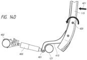
- the tilt system allows the back support 115 to rotate forward when subject to a forwardly directed force on a rearward portion of the back support 115. This can be caused, for example, by the head of a passenger seated behind the seat 105a striking the back support 115, such as during abrupt movements of the aircraft. Accordingly, by allowing the back support 115 to rotate forward when subject to such a force, the force applied to the passenger's head can be reduced.
- the geometry of the quadrants 415 is designed to limit rotation when the quadrants 415 contact the aft base tube 121.
- the back support 115 can pivot in a frontward direction which is further frontward than the standard, upright position illustrated in Figure 14B .
- the quadrants 415 can contact the base tube 121 while still allowing the back support 115 to pivot further frontward to displace and/or absorb additional energy imposed by the frontwardly-directed force 421.
- the quadrants 415 can contact the base tube 121 while in the standard, upright position.
- This reduction in parts subjected to significant forces, as well as the symmetric geometry of the system, provides more consistent, reliable, and predictable energy absorbing qualities.
- the tilt system can include an actuator 1000 for controlling the change in tilt or angular orientation of the back support 115.
- the tilt system can include the same, or similar, structures and features to the tilt system described above in connection with Figures 13 and 14A-D .
- the tilt system can allow the back support 115 to transition from a standard, upright position similar to that shown in Figure 14B to a reclined position similar to that shown in Figure 14C .
- the actuator 1000 can be activated to allow tilting of the back support 115 by pressing a button on the seat.
- the actuator 1000 can be attached to a pivot member 1005 at connection location 1001 of the actuator 1000.
- the actuator 1000 can be positioned within a carrier 1002 which can be attached to tubes 121, such as a fore tube 121 and an aft tube 121.
- the carrier 1002 can be attached to one or both tubes 121 via a clamp. This can beneficially retain the positioning of the actuator 1000 such that the actuator 1000 is retained within the same plane when transitioned from an upright position to a reclined position and from the reclined position to the upright position. This can beneficially increase the usable storage area beneath the actuator 1000 as the actuator 1000 does not rotate or pivot when the tilt system is used. In some embodiments, use of a carrier 1002 can enhance the robustness of the tilt system.
- the pivot member 1005 can include a cross bar 1010 and quadrants 1015.
- the cross bar 1010 can be rotatably coupled at ends 1012 to the quadrants 1015. This can allow the cross bar 1010 to rotate relative to the quadrants 1015.
- the cross bar 1010 can be movably coupled to the carrier 1002.
- the cross bar 1010 can be translatably coupled to the carrier 1002 via use of a fastener 1014 which can slide within a slot 1004 of the carrier 1002.
- the actuator 1000 can be attached to the cross bar 1010 and the quadrants 1015 can be positioned over a portion of the connection frame 120, such as the tube 121 including but not limited to the aft tube 121.
- the quadrants 1015 can be pivotally coupled to the back support 115 at a pivot location 1020.
- the actuator 1000 can be centrally located relative to a width of the seat 105a which can advantageously allow for a more equalized distribution of forces on components of the tilt system during tilting of the back support 115 and head impact. Moreover, the centralized location of the actuator 1000 can advantageously allow for a more symmetric back support 115 and assembly design.
- the tilt system can be independent from the seat pan 110 and thus does not require the bottom pan to articulate when the back support 115 is articulated.
- the actuator 1000 can be positioned within a middle portion of the seat, such as a middle half of the seat with a quarter of the width on both sides of the middle half.
- the actuator 1000 can be positioned within a middle portion of the seat, such as a middle third of the seat with a third of the width on both sides of the middle third of the seat. In some embodiments, the actuator 1000 can be positioned within a middle portion of the seat, such as a middle quarter of the seat.
- Figures 59 and 60 illustrate the positioning of actuator 1000, connection location 1001, and the pivot member 1005 when the back support 115 is in an upright position.
- Figures 61 and 62 illustrate the positioning of actuator 1000, connection location 1001, and the pivot member 1005 when the back support 115 is in an upright position.
- the cross member 1010 of the pivot member 1005 can translate frontwards towards the fore tube 121.
- the cross member 1010 of the pivot member 1005 can translate rearwards towards the aft tube 121.
- the tilt system can also serve as an energy absorbing system for the seat 105a similar to that described above in connection with Figures 14A-14D .
- the aircraft seating assembly 100 can include a retention system, such as retention system 505, to retain an object therein.
- the retention systems can be used to retain a personal electronic device (PED), including small-sized PEDs such as a phone 500a, a medium-sized PED such as a mini tablet 500b, and/or a large-sized PED such as a full-size tablet 500c.
- PED personal electronic device
- the retention systems are positioned such that the object retained within the retention system are within a seated passenger's line of sight; however, the retention systems can also be positioned at other locations of the seat. As shown in the illustrated embodiments, the retention systems are positioned along an upper portion of the seat 105a.
- the retention system 505 can include a clamp member 510 coupled to a base member 515.
- the base member 515 can be attached to a portion of the seat 105a, such as the back support 115.
- the first end 517 of the clamp member 510 can be rotatably coupled to the base member 515 and can include a biasing member such that the clamp member 510 is biased towards a closed or clamped position.
- the clamp member 510 can include a hinge portion 518 having an aperture 519 through which a rotatable coupling can be received for coupling the clamp member 510 to the base member 515.
- the clamp member 510 can include protrusion 520 which can serve as a surface upon which the object, such as personal electronic device 500c, can rest.
- the clamp member 510 can be rotatably attached to the base member 515 along a portion of the clamp member 510 between the first end 517 and second end 521 of the clamp member 510.
- the clamp member 510 can include a lower portion 525.
- This lower portion 525 can beneficially reduce the likelihood that the clamp member 510 will block a passenger's view of the object, such as a screen of a PED, when the object is retained by the clamp member 510.
- the lower portion 525 can be positioned centrally along the clamp member 510 as a passenger may be likely to position the PED centrally relative to the width of the clamp member 510; however, the lower portion 525 can be positioned along other portions of the clamp member 510 as desired.
- the clamp member 510 can include one or more raised portions 530 which can facilitate a passenger's grasping of the clamp member 510 to rotate the clamp member 510 relative to the base member 515 in order to insert an object into the retention system 505 and/or remove an object from the retention system 505.
- the retention system 505 can include one or more dampers 535.
- the dampers 535 can be used in conjunction with biasing members to apply a force in a direction opposite that of the force applied by a biasing member of the retention system 505. This can advantageously control the velocity, and the force, of the clamp member 510 thereby reducing the likelihood of damage to objects positioned within the retention system 505.
- the damper 535 is a linear damper attached to the base member 515.
- the damper 535 can be one or more rotational damper 1135 (as shown in Figure 63 ). The rotational damper can be positioned along, or to rotate along, an axis of rotation 538 of the clamp member 510.
- the clamp member 510 can include one or more raised ridges 540 projecting outwardly from an inner surface of the clamp member 510.
- the raised ridges 540 can have a first thickness along a first portion 545 of the ridge 540 and a second thickness along a second portion 550 of the ridge 540. As shown in the illustrated embodiment, the first thickness can be less than the second thickness. This can beneficially allow the clamp member 510 to more securely retain a wider range of PED sizes.
- the raised ridges 540 can include additional thicknesses along other portions. In some embodiments, the raised ridges 540 can have a constant thickness throughout.
- the one or more ridges 540 can be formed from a material having a low shore hardness, such as rubber, to reduce the likelihood of scratching surfaces of the object. In some embodiments, the one or more ridges 540 can be formed from a material having a high friction coefficient to more strongly secure the object to the retention system 505.
- the retention system 1105 can include a clamp member 1110 coupled to a base member 1115.
- the retention system 1105 can include the same, or similar, structures and features to the retention systems 505 described above.
- the base member 1115 can be attached to a portion of the seat 105a, such as the back support 115.
- the first end 1117 of the clamp member 1110 can be rotatably coupled to the base member 1115.
- the clamp member 1110 can include a shaft 1111 at or proximate the first end 1117 to rotatably couple the clamp member 1110 to the base member 1115.
- the clamp member 1110 can include a biasing member such that the clamp member 1110 is biased towards a closed or clamped position.
- one or more biasing members 1112 can form part of the rotatable coupling. As shown in the illustrated embodiment, the one or more biasing members 1112 can be in line with the shaft 1111.
- the clamp member 1110 can be rotatably attached to the base member 1115 along a portion of the clamp member 1110 between the first end 1117 and second end 1121 of the clamp member 1110 similar to that illustrated in Figure 19 .
- the clamp member 1110 can include a latch 1150.
- the clamp member 1110 can include protrusion 1120 which can serve as a surface upon which the object, such as personal electronic device 500c, can rest.
- the clamp member 1110 can include a one or more ports 1114 which can provide a power and/or data connection.
- the one or more ports 1114 can be a power outlet, a USB port, and the like. This can advantageously allow a user to plug in their personal electronic device to the seat.
- the clamp member 1110 can include a lower portion 1125.
- This lower portion 1125 can beneficially reduce the likelihood that the clamp member 1110 will block a passenger's view of the object, such as a screen of a PED, when the object is retained by the clamp member 1110.
- the lower portion 11125 can be positioned centrally along the clamp member 1110 as a passenger may be likely to position the PED centrally relative to the width of the clamp member 1110; however, the lower portion 1125 can be positioned along other portions of the clamp member 1110 as desired.
- the clamp member 1110 can include one or more raised portions 1130 which can facilitate a passenger's grasping of the clamp member 1110 to rotate the clamp member 1110 relative to the base member 1115 in order to insert an object into the retention system 1105 and/or remove an object from the retention system 1105.
- the clamp member 1110 can include one or more raised ridges 1140 projecting outwardly from an inner surface of the clamp member 1110.
- the raised ridges 1140 can have a first thickness along a first portion 1145 of the ridge 1140 and a second thickness along a second portion 1150 of the ridge 1140. As shown in the illustrated embodiment, the first thickness can be less than the second thickness. This can beneficially allow the clamp member 1110 to more securely retain a wider range of PED sizes.
- the raised ridges 1140 can include additional thicknesses along other portions. In some embodiments, the raised ridges 1140 can have a constant thickness throughout.
- the one or more ridges 1140 can be formed from a material having a low shore hardness, such as rubber, to reduce the likelihood of scratching surfaces of the object. In some embodiments, the one or more ridges 1140 can be formed from a material having a high friction coefficient to more strongly secure the object to the retention system 1105.
- the retention system 1105 can include one or more dampers 1135.
- the one or more dampers 1135 can be used in conjunction with one or more biasing members 1112 to apply a force in a direction opposite that of the force applied by a biasing member of the retention system 1105. This can advantageously control the velocity, and the force, of the clamp member 1110 thereby reducing the likelihood of damage to objects positioned within the retention system 1105.
- the damper 1135 is a rotational damper attached to the base member 1115.
- a rotational damper 1135 can be beneficial in that it can apply a relatively constant amount of damping throughout the range of motion of the clamp member 1110.
- the damper 1135 can have a rotatable member 1136 which engages with a ramped feature 1137 of the clamp member 1110.
- the rotatable member 1136 can rotate as the clamp member 1110 is pivoted relative to the base member 1115.
- the rotatable member 1136 and the ramped feature 1137 can include engagement structures, such as teeth, to reduce the likelihood of slippage between the rotatable member 1136 and the ramped feature 1137.
- the damper 1135 can be positioned along, or to rotate along, an axis of rotation of the clamp member 1110.
- the damper 1135 can rotate along an axis of the shaft 1111.
- the retention system 560 can include a fold-out tray member 565 which can be rotatably attached to a base member 570.
- the tray member 565 can include various ridges 575 to allow for variable positioning, such as tilt, of the object retained thereon.
- the retention system 560 can include a slot or pocket 580 to retain an upper portion of the object.
- the retention system 590 can include a slot 595 formed in the base member 596.
- a baggage bar 122 of the connection frame 120 can be attached to a tube 121 via a mount 123.
- the design of the mount 123 can advantageously allow and upper portion of baggage bar 122 to be placed anywhere along the length of the tube 121. This can be beneficial as it can allow the same mount 123 to be used on any type of seat assembly.
- a storage compartment 124 can be positioned under the seat pan 110. As shown in the illustrated embodiment, the storage compartment 124 can be attached to a tube 121 of the connection frame 120. The location of the storage compartment 124 can improve living space because it is located underneath the seat pan 110 while still being located above a typical location for luggage stored under a seat. The tilt of the storage compartment 124 can allow the passenger to more easily store and retrieve an object therein. In some embodiments, the storage compartment 124 can be sized and shaped to store water bottles of various sizes during flight.
- the armrest 125 can be designed to reduce the likelihood of finger pinching. As shown in the illustrated embodiment, concentric shapes of the armrest 125, finger guard 126, and spreader 127 can reduce or eliminate the areas of potential finger pinch as armrest travels through its range of motion
- the armrest 125 can be rotatably coupled to a spreader 127.
- the armrest can include a clamp member 128 which can be tightened against the spreader 127.
- the clamp member 128 can be tightened via two fasteners, such as screws or bolts, on opposite sides of an aperture 129 for receiving a rotatable coupling, such as an armrest pivot shaft, between the armrest 125 and the spreader 127.
- Use of fasteners on opposite sides of the aperture 129 can provide a more consistent distribution of clamping force against the rotatable coupling and can reduce looseness in the armrest.
- the illustrated spreader 127 and clamp member 128 design can beneficially allow for quick adjustment of friction force to resist up and down rotation of armrest to stow and deploy and/or removal of the armrest 125 from the spreader 127.
- the fasteners can be tightened to increase friction force and can be loosened to reduce friction force.
- a friction bearing insert can be positioned between the clamp member 128 and the spreader 127 to provide a more consistent friction force.
- the armrest 125 can be formed from multiple portions.
- the armrest 125 can be formed from a first base portion 600, a second base portion 605, and a cap portion 610.
- the first base portion 600 and the second base portion 605 can be mated to form a base of the armrest 125.
- the first base portion 600 and the second base portion 605 are mated at a symmetric centerline of the base; however, these portions can be mated at other locations.
- the first base portion 600 and the second base portion 605 can be fastened together using mechanical fasteners, such as screws, bolts, turnbuckles, and the like, and/or chemical fasteners, such as an adhesive.
- the first base portion 600 and the second base portion 605 can include keyed features, such as pins, to ensure that the mating surfaces are properly aligned prior to fastening.
- the first base portion 600 and the second base portion 605 can form keyways 615 to facilitate connection of the cap portion 610 to the armrest assembly.
- Mounting screws 620 can be partially threaded into the cap portion 610 prior to alignment.
- the mounting screws 620 can be sized such that the head can pass through the large opening of the keyway 615 and the cap portion 610 can be translated along the keyway 615 into proper alignment with the base of armrest 125.
- the base of the armrest 125 can include holes 625 along a bottom portion to allow mounting hardware, such as a screwdriver, to pass therethrough for tightening the mounting screws 620 after the cap portion 615 is aligned with respect to the base of the armrest 125. This arrangement can beneficially facilitate installation and removal of the cap portion 610 from the armrest 125.
- the spreader 127 can include a photo luminescent material 630.
- This photo luminescent material 630 can be used as a proximity light when light within the cabin is reduced.
- the photo luminescent material 630 can provide passengers with an indicator as to positioning of the various rows of aircraft seating assemblies.
- the photo luminescent material 630 can have various colors or shapes to provide passengers with additional information.
- the photo luminescent material 630 can provide passengers with information for offboarding the plane during an emergency operation. This can beneficially eliminate having to include a proximity light to the assembly and can advantageously decrease weight, decrease assembly time, and improve reliability
- the aircraft seat 105a can include a tray table 130.
- the tray table 130 can be coupled to the aircraft seat 105a via a cross bar 750 attached to arms 700.
- the arms 700 can include an elongate member 705 and a clamp member 710 which can be tightened against the elongate member 705.
- the clamp member 710 can be tightened via two fasteners 711, such as screws, bolts or the like, on opposite sides of an aperture for receiving a rotatable coupling, such as a pivot shaft 715, of the arm 700.
- fasteners 711 on opposite sides of the pivot shaft 715 can provide a more consistent distribution of clamping force against the rotatable coupling and can reduce looseness in the arm 700 thereby reducing looseness in the tray table 130.
- the illustrated design can beneficially allow for quick adjustment of the friction force to rotate the tray table 130 from a stowed position to a use position where the tray table 130 can be used as a table by the passenger and vice versa.
- the fasteners can be tightened to increase friction force and can be loosened to reduce friction force.
- the illustrated embodiment can facilitate installation and removal of the arms 700.
- a friction bearing insert can be positioned between the clamp member 710 and the elongate member 705 to provide a more consistent friction force.
- One or both arms 700 can include a stop member 720 to limit rotation of the arm 700 and thereby limit rotation of the tray table 130.
- the stop member 720 can limit rotation of the tray table 130 such that it can only rotate to a position generally parallel to the floor of the aircraft.
- the cross bar 750 can be rotatably coupled to the arms 700 via a shaft 755.
- the shaft 755 can be coupled relative to the cross bar 750 such that the shaft 755 applies a frictional force to the cross bar 750 as the cross bar 750 is rotated relative to the shaft 755.
- the cross bar 750 can include a fastener 760, such as a screw, bolt or the like, to increase or decrease friction on the shaft 755.
- the illustrated clamp design on the cross bar 750 can advantageously provide consistent clamping force on shaft 755.
- the clamp design provides quick adjustment of friction force and adjustment for play/looseness in tray 130 and associated components.
- the fastener 760 can be tightened to increase friction force and can be loosened to reduce friction force.
- a friction bearing insert can be positioned between the cross bar 750 and the shaft 755 to provide a more consistent friction force.
- the cross bar 750 can include an elongate member 765 which can extend into a cavity of the tray table 130.
- the tray table 130 can slidably translate along the elongate member 765 and can be retained in a specific position, relative to the elongate member 765, by tightening a fastener 770, such as a screw, bolt or the like, which can clamp the tray table 130 to the elongate member 765.
- a fastener 770 such as a screw, bolt or the like
- This can beneficially allow the vertical spacing of the tray table 130 relative to the cross bar 750 to be adjusted to ensure that the tray 130 is properly positioned with respect to the seat 105a. This can help to ensure that the tray 130 can be properly retained in the stowed position by a latch assembly.
- the tray table 130 can be formed from a first portion 131 coupled to a second portion 132.
- the first portion 131 and the second portion 132 can form a clamshell design and have an interlocking feature 133 to retain the tray table 130 in an assembled state.
- This two piece clamshell design can advantageously allow the two portions 131, 132 to mate with one another around the exterior surfaces of the shells which can include straight surfaces, curved surfaces, drafted surfaces, and undercuts.
- this design can advantageously allow various components to be positioned within the tray table 130.
- a tray table 1200 can include a first portion 1205, such as a bottom portion, and a second portion 1210, such as a top portion.
- the tray table 1200 can be coupled to a cross bar, such as cross bar 750.
- the second portion 1210 can extend over the cross bar 750 along a front portion 1215 of the second portion 1210. This can beneficially enhance the usable surface area of the tray table 1200.
- the second portion 1210 In the stowed position, the second portion 1210 can be positioned adjacent a seat back.
- the front portion 1215 can be positioned between the seat back and at least a portion of the cross bar 750.
- the tray tables 130, 1200 can be retained in a stowed position via a latch 135.
- the latch 135 can be rotatably coupled to the retention system 505, such as the base member 515. Accordingly, when in an unlatched position as shown in Figure 44 , the latch 135 can be positioned between the base member 515 and the clamp member 510. This can beneficially protect a passenger's head from strike against the latch 135 during abrupt movements of the aircraft. As shown in the illustrated embodiment, the latch 135 can be rotated from a latched position to an unlatched position via approximately a one-quarter turn rotation.
- the structures of the aircraft seating assembly 100 can include cable management systems to beneficially improve packaging and increase the living space for passengers.
- back support 115 can include recesses 800 configured to allow cables 805 and other components to pass therethrough.
- cables 805 and other components can pass through a cavity 810 of the back support frame 300.
- the retention system 505 can include a channel 597 to allow a wire to pass through towards the PED 400c.
- aircraft seating assembly 100 be designed such that components, such as the tray table 130, the retention system 505, and/or the lower net pocket 140, are positioned to be flush with, or at least substantially flush with, a rearmost portion of the back support 115.
- the aircraft seating assembly 100 can be designed such that the components, such as the tray table 130, the retention system 505, and/or the lower net pocket 140, are sub- flush with, or at least substantially sub-flush with, a rearmost portion of the back support 115. This can advantageously provide increased passenger living space.
- the arms 700 of the tray table 130 are positioned laterally outward of the back support 115. This can beneficially increases reliability, stability, and ease of removal/servicing/adjustment by having tray arms not nested in back structure.
- any value of a threshold, limit, duration, etc. provided herein is not intended to be absolute and, thereby, can be approximate.
- any threshold, limit, duration, etc. provided herein can be fixed or varied either automatically or by a user.
- relative terminology such as exceeds, greater than, less than, etc. in relation to a reference value is intended to also encompass being equal to the reference value. For example, exceeding a reference value that is positive can encompass being equal to or greater than the reference value.
- relative terminology such as exceeds, greater than, less than, etc. in relation to a reference value is intended to also encompass an inverse of the disclosed relationship, such as below, less than, greater than, etc. in relations to the reference value.
Landscapes
- Engineering & Computer Science (AREA)
- Aviation & Aerospace Engineering (AREA)
- Transportation (AREA)
- Mechanical Engineering (AREA)
- Physics & Mathematics (AREA)
- Thermal Sciences (AREA)
- Seats For Vehicles (AREA)
- Connection Of Plates (AREA)
- Pivots And Pivotal Connections (AREA)
Abstract
Description
- The embodiments described herein relate generally to seat devices, systems, and methods. In particular, some embodiments described herein relate to aircraft seat devices, systems, and methods.
- The structure of aircraft seats plays a significant role in the airline industry. As passenger seating is typically arranged in rows with one or more aisles separating parts of each row, aircraft seating assemblies typically are configured as 2, 3 or 4 seat units. These aircraft seating assemblies have a structure for withstanding forces caused not only due to acceleration and deceleration of the aircraft during normal operation, but also substantial forces caused during emergencies. Significantly, the aircraft seats desirably achieve this performance while being relatively lightweight. Further, while the structural integrity and weight of the seating assemblies is important, the cost of the assemblies is also an important consideration.
- While there are many existing aircraft seat assemblies, such seating assemblies and certain components thereof have various limitations and disadvantages.
- Embodiments of an aircraft seating assembly are disclosed which are both compliant with industry regulations and lightweight yet capable of withstanding significant forces. In some embodiments, the aircraft seating assembly can be installed in an aircraft. The assembly can include a seat pan, a connection frame, and one or more mounts. The one or more mounts can removably couple the seat pan to the connection frame. The one or more mounts can be attached to a bottom portion of the seat pan.
- In some embodiments, the aircraft seating assembly can include a back support. The back support can include a back support frame and a cushioning member. The cushioning member can be removably coupled to the back support frame.
- In some embodiments, the aircraft seating assembly can include a connection frame, a back support, and a tilt system. The back support can be coupled to the connection frame. The tilt system can be coupled to the back support and to the connection frame. The tilt system can allow the back support to articulate relative to a connection frame. The tilt system can include a pivot member and an actuator. The actuator can include a first end and a second end. The actuator can be coupled to the connection frame at the first end and the pivot member at the second end. The actuator can be centrally located relative to a width of a seat of the aircraft seating assembly.
- In some embodiments, the aircraft seating assembly can include a connection frame, a back support, and a tilt system. The back support can be coupled to the connection frame. The tilt system can be coupled to the back support and to the connection frame. The tilt system can allow the back support to articulate relative to a connection frame. The tilt system can include a pivot member, a carrier and an actuator. The carrier can be coupled to the connection frame. The actuator can be positioned within the carrier and can be coupled to the pivot member.
- In some embodiments, the aircraft seating assembly can include a back support and a retention system. The retention system can be coupled to the back support. The retention system can retain an object in place when in a closed configuration. The retention system can include a base member, a clamp member and a biasing component. The clamp member can be rotatably coupled to the base portion. The biasing component can bias the clamp member into the closed configuration.
- Embodiments of the present disclosure will now be described hereinafter, by way of example only, with reference to the accompanying drawings as indicated below.
-
Figure 1 is a front perspective view of an embodiment of an aircraft seating assembly. -
Figure 2 is a bottom perspective view of the aircraft seating assembly ofFigure 1 . -
Figure 3A is a front perspective view of an embodiment of a seat pan. -
Figure 3B is a top view of the seat pan ofFigure 3A . -
Figure 3C is a sectional view of the seat pan ofFigure 3B along line "3C." -
Figure 3D is a front view of the seat pan ofFigure 3A . -
Figure 3E is a sectional view of the seat pan ofFigure 3D along line "3E." -
Figure 4A is a perspective view of the seat pan ofFigure 3A shown in a first configuration. -
Figure 4B is a perspective view of the seat pan ofFigure 4A shown in a second configuration. -
Figure 5A is a perspective view of an embodiment of a mount of the seat pan ofFigure 3A . -
Figure 5B is a perspective view of an embodiment of a strap of the mount ofFigure 5A . -
Figure 6 is a front perspective view of an embodiment of an aircraft seating assembly with a removable cushioning member. -
Figure 7 is a perspective view of an embodiment of a coupling member for coupling a cushioning member with a back support frame. -
Figure 8 is a rear perspective view of an embodiment of a cushioning member of the aircraft seating assembly ofFigure 6 . -
Figure 9 is a cross-sectional view of a seat of the aircraft seating assembly ofFigure 6 . -
Figure 10 is an enlarged view of the cross-sectional view ofFigure 9 . -
Figure 11 is a cross-sectional view of an embodiment of the aircraft seating assembly ofFigure 6 . -
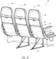
Figure 12 is a rear perspective view of the aircraft seating assembly ofFigure 1 . -
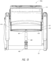
Figure 13 is a top view of a tilt system of an aircraft seat. -
Figure 14A is a perspective view of the tilt system ofFigure 13 . -
Figure 14B is a side view of the tilt system ofFigure 13 in a first position. -
Figure 14C is a side view of the tilt system ofFigure 13 in a second position. -
Figure 14D is a side view of the tilt system ofFigure 13 in third position. -
Figure 15 is a rear view of an embodiment of a retention system of an aircraft seat. -
Figure 16 is a side view of the retention system ofFigure 15 . -
Figure 17A is a side perspective view of an embodiment of a clamp member of the retention system ofFigure 15 . -
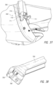
Figure 17B is a side perspective view of an embodiment of a damper system of the retention system ofFigure 15 . -
Figure 18 is a front view of another embodiment of a clamp member of the retention system ofFigure 15 . -
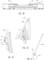
Figure 19 is a schematic, side view of another embodiment of a retention system. -
Figure 20 is a schematic, side view of another embodiment of a retention system. -
Figure 21 is a schematic, side view of another embodiment of a retention system. -
Figure 22 is a bottom view of an embodiment of a seat pan and an upholstery cover. -
Figure 23 is a rear perspective view of another embodiment of an aircraft seat. -
Figure 24 is a rear perspective view of another embodiment of an aircraft seat with a personal electronic device retained on a retention system. -
Figure 25 is a rear perspective view of an embodiment of a mount for coupling a baggage bar to a connection frame. -
Figure 26 is a front perspective view of the mount ofFigure 25 . -
Figure 27A is a front perspective view of an embodiment of an aircraft seating assembly having a storage compartment. -
Figure 27B is a side view of the storage compartment ofFigure 27A . -
Figure 28 is a rear perspective view of an embodiment of an armrest in a first configuration. -
Figure 29 is a rear perspective view of the armrest ofFigure 28 in a second configuration. -
Figure 30 is a front perspective view of the armrest ofFigure 28 . -
Figure 31 is a front perspective view of the armrest ofFigure 29 . -
Figure 32 is a partial, cross-sectional view of the armrest ofFigure 28 . -
Figure 33 is a perspective view of an embodiment of an armrest having multiple components. -
Figure 34 is a perspective view of the armrest ofFigure 33 in a partially assembled state. -
Figure 35 is a bottom perspective view of components of the armrest ofFigure 33 in an assembled state. -
Figure 36 is a perspective view of an embodiment of a spreader with a photo luminescent material. -
Figure 37 is a perspective view of an embodiment of an arm for a tray table. -
Figure 38 is a perspective view of an embodiment of a cross bar for a tray table. -
Figure 39 is a rear view of an embodiment of an aircraft seat with a arms ofFigure 37 and cross bar ofFigure 38 . -
Figure 40 is a perspective view of an embodiment of a cross bar for a tray table having an elongate member. -
Figure 41 is a perspective view of an embodiment of a tray table. -
Figure 42 is a cross-sectional view of the tray table ofFigure 41 . -
Figure 43 is a rear view of an embodiment of a latch in a latched position. -
Figure 44 is a rear view of the latch ofFigure 43 in an open position. -
Figure 45 is a perspective view of the latch ofFigure 43 in a latched position. -
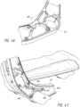
Figure 46 is a perspective view of an embodiment of a cable management system in support structures of an aircraft seat. -
Figure 47 is a perspective view of an embodiment of a cable management system in support structures of an aircraft seat. -
Figure 48 is a cross-sectional view of an embodiment of a cable management system in a back support frame of an aircraft seat. -
Figure 49 is a perspective view of an embodiment of a cable management system for a personal electronic device. -
Figure 50 is a perspective view of components of the cable management system ofFigure 49 . -
Figure 51 is a perspective view of an embodiment of an aircraft seating assembly. -
Figure 52 is a rear perspective view of the aircraft seating assembly ofFigure 51 . -
Figure 53 is a bottom perspective view of a seat pan having another embodiment of mounts. -
Figure 54 is a bottom perspective view of the seat pan and mounts ofFigure 53 coupled to an aircraft seating assembly. -
Figure 55 A is a schematic view of the seat pan and mounts ofFigure 53 in a second configuration. -
Figure 55B is a top perspective view of the seat pan and mounts ofFigure 53 coupled to an aircraft seating assembly in a second configuration. -
Figure 56 is a side view of a mount shown inFigure 53 in a second configuration. -
Figure 57 is a side view of a mount shown inFigure 53 in a decoupled configuration. -
Figure 58 is a top perspective view of another embodiment of a tilt system. -
Figure 59 is a top perspective view of the tilt system ofFigure 58 in a first position. -
Figure 60 is a bottom perspective view of the tilt system ofFigure 58 in a first position. -
Figure 61 is a top perspective view of the tilt system ofFigure 58 in a second position. -
Figure 62 is a bottom perspective view of the tilt system ofFigure 58 in a second position. -
Figure 63 is a front perspective view of another embodiment of a retention system. -
Figure 64 is a rear perspective view of the retention system ofFigure 63 . -
Figure 65 is a rear perspective view of an embodiment of a clamp of the retention system ofFigure 63 . -
Figure 66 is a top perspective view of another embodiment of a tray table. - The following detailed description is merely illustrative in nature and is not intended to limit the embodiments of the subject matter or the application and uses of such embodiments. Any implementation described herein as exemplary is not necessarily to be construed as preferred or advantageous over other implementations. Furthermore, there is no intention to be bound by any expressed or implied theory presented in the proceeding technical field, background, brief summary, or the following detailed description.
- Certain terminology may be used in the following description for the purpose of reference only, and thus are not intended to be limiting. For example, terms such as "upper", "lower", "above", and "below" refer to directions in the drawings to which reference is made. Terms such as "front", "back", "rear", "left side," and "right side" describe the orientation and/or location of portions of the component within a consistent but arbitrary frame of reference which is made clear by reference to the text and the associated drawings describing the component under discussion. Such terminology may include the words specifically mentioned above, derivatives thereof, and words of similar import. Similarly, the terms "first", "second", and other such numerical terms referring to structures do not imply a sequence or order unless clearly indicated by the context.
- With reference first to
Figures 1 and 2 , which are illustrations of an embodiment of anaircraft seating assembly 100, theaircraft seating assembly 100 can include threeseats aircraft seating assembly 100 may be expanded to include additional seats or reduced to include fewer seats. In some embodiments, theaircraft seating assembly 100 can include four seats. In some embodiments, theaircraft seating assembly 100 can include a single seat or two seats. Since theseats seat 105a will be described in detail; however, it should be understood that the same, or similar, structures and features can be utilized forseats first seat 105a can include aseat pan 110, aback support 115, aconnection frame 120, and anarmrest 125. Theaircraft seating assembly 100 is designed to be placed within the cabin of an aircraft and attached to the cabin via theconnection frame 120. - With reference now to
Figures 2-5 , in some embodiments theseat pan 110 can be connected to theconnection frame 120. As shown in the illustrated embodiment ofFigure 2 , in some embodiments theseat pan 110 can be removably coupled to one ormore tubes 121 of theconnection frame 120, such as a fore tube positioned nearer afront portion 111 of theseat pan 110 and an aft tube positioned nearer arear portion 114 of theseat pan 110. Thesetubes 121 can extend along the width of theaircraft seating assembly 100. Theseat pan 110 can be removably coupled to thesetubes 121 with one or more mounts 200. In the illustrated embodiment, fourmounts 200 are attached to a bottom of theseat pan 110 and are attached at four, spaced apart corners of theseat pan 110. In some embodiments, themounts 200 can advantageously be arranged to allow theseat pan 110 to more easily flex along portions which are spaced from the mounting points of themounts 200. This greater ability for theseat pan 110 to flex can allow for a morecompliant seat pan 110 thereby enhancing comfort for the passenger. As shown in the illustrated embodiment, themounts 200 can be generally located under the passenger's thighs and buttock to provide substantial support for the passenger. In some embodiments, fewer or greater number ofmounts 200 can be used to removably attach the seat pan to theconnection frame 120 and/or themounts 200 can be positioned at other locations relative to theseat pan 110 as desired. - With reference to
Figures 3A-3E , theseat pan 110 can include features which significantly enhance passenger comfort. For example, as shown in the illustrated embodiment, theseat pan 110 can include a waterfall feature along afront portion 111 of theseat pan 110 and/or along one or bothside portions 112 of theseat pan 110. As shown in the illustrated embodiment, theseat pan 110 can have an upward slope from therear portion 114 of theseat pan 110 towards thefront portion 111 of theseat pan 110. Proximate an edge of thefront portion 111, theseat pan 110 can slope towards the floor of the aircraft. As shown in the illustrated embodiment, the edge of thefront portion 111 of theseat pan 110 can have an angle of about 1 to about 45 degrees relative to aplane 116 perpendicular to the aircraft floor, an angle of about 5 to about 30 degrees relative to theplane 116, an angle of about 10 to about 15 degrees relative to theplane 116, any sub-range within these ranges, and/or any other angle as desired. In some embodiments, the transition from the upward slope to the downward slope can be gradual and can include a generally roundedsurface 118. - As shown in the illustrated embodiment, the
seat pan 110 can have an upward slope from thecentral portion 113 of theseat pan 110 towards one or bothside portions 112 of theseat pan 110. Proximate an edge of one or both theside portions 112, theseat pan 110 can slope towards the floor of the aircraft. As shown in the illustrated embodiment, the edge of one or bothsides portions 112 of theseat pan 110 can have an angle of about 1 to about 45 degrees relative to aplane 117 perpendicular to the aircraft floor, an angle of about 5 to about 30 degrees relative to theplane 117, an angle of about 10 to about 15 degrees relative to theplane 117, any sub-range within these ranges, and/or any other angle as desired. In some embodiments, the transition from the upward slope to the downward slope can be gradual and can include a generally roundedsurface 119. In some embodiments, thefront portion 111 and/or one or bothside portions 112 can be angled towards the floor of the aircraft. The waterfall feature can advantageously enhance passenger comfort by reducing pressure points on a passenger's legs while the passenger is seated. As another example, theseat pan 110 can be relatively flexible to allow for a greater degree of compliancy. This greater flexibility can significantly enhance passenger comfort while the passenger is seated. - With reference to
Figures 4 A and4B , in some embodiments themounts 200 can allow theseat pan 110 to articulate. In some embodiments, theseat pan 110 can rotate and/or translate relative to theconnection frame 120. For example, as shown in the illustrated embodiment, themounts 200 can allow theseat pan 110 to be rotated from afirst configuration 110a as shown inFigure 4A , such as a fully attached configuration, to asecond configuration 110b as shown inFigure 4B , such as a maintenance configuration, without having to completely detach theseat pan 110 from theconnection assembly 120. For example, to rotate theseat pan 110 in the manner illustrated, only the tworear mounts 200 need to be disconnected. This can advantageously facilitate maintenance, inspection, and assembly of theaircraft seating assembly 100. - With reference to
Figures 5 A and5B , in some embodiments themounts 200 can include astrap 205 which can releasably couple themount 200 to theconnection frame 120. Thestrap 205 can be formed from a material having some degree of compliancy such that the strap can be loosened. As shown inFigure 5B , thestrap 205 can include a flexible,elongate member 206 with acoupling member 207. Thecoupling member 207 can be used to lock theelongate member 206 in a desired position and/or apply tension to theelongate member 206. As shown in the illustrated embodiment, thecoupling member 207 can be a worm gear or similar device. This strap-style mount 200 advantageously does not require holes to be drilled along thetube 121 to secure themount 200 to theconnection frame 120. This can be particularly beneficial as such drilling can decrease the strength of the 121. Moreover, as the strap-style mount 200 can be removably coupled to theconnection frame 120 without drilling holes, the strap-style mount 200 provides greater flexibility in choosing where to position the seat along the width of theaircraft seating assembly 100. In some embodiments, interior and/or exterior surfaces of theelongate member 206 can be provided with an interior lining to reduce the likelihood of damage to components to which theelongate member 206 is in contact, such astube 121. - As shown in the illustrated embodiment, the
mounts 200 can include afirst member 210 and asecond member 215. The first andsecond members second members hinge 220. In some embodiments, the first andsecond members first member 210 can be attached to theconnection frame 120 and thesecond member 215 can be attached to theseat pan 110. Such a design can allow theseat pan 110 to be rotatable as shown inFigure 4 . - With reference now to
Figures 53-57 , another embodiment ofmounts seat pan 110 to theconnection frame 120, such as thetubes 121. Themounts - With reference first to
Figures 53 and 54 , in some embodiments theseat pan 110 can be removably coupled to one ormore tubes 121 of theconnection frame 120, such as a fore tube positioned nearer afront portion 111 of theseat pan 110 and an aft tube positioned nearer arear portion 114 of theseat pan 110. Thesetubes 121 can extend along the width of theaircraft seating assembly 100. Theseat pan 110 can be removably coupled to thesetubes 121 with one ormore mounts mounts 900 and twomounts 950 are attached to a bottom of theseat pan 110 and are attached at four, spaced apart corners of theseat pan 110, with themounts 900 being positioned nearer arear portion 114 of theseat pan 110 and themounts 950 being positioned nearer afront portion 111 of theseat pan 110. However, it should be understood that themounts 900 and themounts 950 can be positioned at any position on theseat pan 110 including the reverse of the configuration described above. - In some embodiments, the
mounts seat pan 110 to more easily flex along portions which are spaced from the mounting points of themounts seat pan 110 to flex can allow for a morecompliant seat pan 110 thereby enhancing comfort for the passenger. As shown in the illustrated embodiment, themounts mounts connection frame 120. - With reference to
Figures 55-57 , in some embodiments themounts straps mounts connection frame 120.Straps Figures 56 and 57 , thestraps elongate members coupling members elongate member 206 andcoupling member 207 described above. Thecoupling members elongate members elongate members coupling members tube 121 to secure themounts connection frame 120. In some embodiments, interior and/or exterior surfaces of theelongate members elongate members tube 121. In some embodiments, theelongate members coupling members - As shown in
Figure 55 , themounts seat pan 110 to be rotated relative to thetubes 121 of theconnection assembly 120. For example, as shown in the illustrated embodiment, theseat pan 110 is rotated clockwise about afore tube 121. In some embodiments, portions of themounts tubes 121 while other portions of themounts seat pan 110 can be rotated in a counter-clockwise direction along anaft tube 121. - With reference next to
Figure 56 , themount 900 can include afirst member 910 and asecond member 915. The first andsecond members second members ball stud fastener 920 andcorresponding receiver 925 which can facilitate coupling and decoupling the first andsecond members second members second member 915 can include theball stud fastener 920 which can extend downwardly from abottom surface 917 of thesecond member 915. Thefirst member 910 can include thestud receiver 925 which can open upwardly along an upper surface 912 of thefirst member 910. Other types of coupling mechanisms can be used, such as mechanical coupling mechanisms including clips, screws, hook-and-loop fasteners, chemical coupling mechanisms such as adhesives, any other coupling mechanism as desired, and/or any combination of coupling mechanisms. - In some embodiments, the
mount 900 can include features which can reduce or inhibit translational and/or rotational motion. For example, themount 900 can include aprotrusion 930 and a corresponding detent orrecess 935 in which theprotrusion 930 can be received. As shown in the illustrated embodiment, thefirst member 910 can include theprotrusion 930 along an upper surface 912 of thefirst member 910. Thesecond member 915 can include the detent orrecess 935 which can open downwardly of thebottom surface 917 of thesecond member 915. When the first andsecond members protrusion 930 can be received within the detent orrecess 935 which can inhibit translation in a horizontal plane and/or rotation along an axis perpendicular to the horizontal plane. This can advantageously reduce stresses applied to the coupling mechanism, such as theball stud fastener 920 andcorresponding receiver 925. - In some embodiments, an
upper surface 919 of thesecond member 915 can be coupled to the bottom of theseat pan 110 such as via mechanical coupling mechanisms including clips, screws, hook-and-loop fasteners, chemical coupling mechanisms such as adhesives, any other coupling mechanism as desired, and/or any combination of coupling mechanisms. Theupper surface 919 of thesecond member 915 can be correspondingly shaped to the bottom surface of theseat pan 110. For example, theupper surface 919 of thesecond member 915 can include a curve. - With reference to
Figure 57 , themount 950 can include afirst member 960 and asecond member 965. The first andsecond members second members pin 970 andcorresponding slot 975 which can facilitate coupling and decoupling the first andsecond members second members first member 960 can include thepin 970 which can extend laterally outward from aside surface 962 of thefirst member 960. Thesecond member 965 can include theslot 975. This can allow the first andsecond members - As shown in the illustrated embodiment, the first and
second members second members first member 960 can include a stop which can contact a surface of thesecond member 965 upon reaching a desired angle. In some embodiments, further rotation beyond this angle can allow theslot 975 to disengage thepin 970 thereby decoupling thefirst member 960 from thesecond member 965. This can beneficially reduce the likelihood of damage due to over-rotation of theseat pan 110. In some embodiments, theslot 975 can be disengaged from thepin 970 by applying a force on thesecond member 965 in a direction opposite the opening of theslot 975. For example, as shown in the illustrated configuration ofFigure 57 , thesecond member 965 can be decoupled from thefirst member 960 by applying a force on thesecond member 965 in a vertical direction. - In some embodiments, the
mount 950 can include features which can reduce or inhibit translational and/or rotational motion. For example, themount 950 can include aprotrusion 980 and a corresponding detent or recess (not shown) in which theprotrusion 980 can be received. As shown in the illustrated embodiment, thefirst member 960 can include theprotrusion 980 along anupper surface 964 of thefirst member 960. Thesecond member 965 can include the detent or recess which can open downwardly of thebottom surface 967 of thesecond member 965. When the first andsecond members protrusion 980 can be received within the detent or recess which can inhibit translation in a horizontal plane and/or rotation along an axis perpendicular to the horizontal plane. - In some embodiments, an
upper surface 969 of thesecond member 965 can be coupled to the bottom of theseat pan 110 such as via mechanical coupling mechanisms including clips, screws, hook-and-loop fasteners, chemical coupling mechanisms such as adhesives, any other coupling mechanism as desired, and/or any combination of coupling mechanisms. Theupper surface 969 of thesecond member 965 can be correspondingly shaped to the bottom surface of theseat pan 110. For example, theupper surface 969 of thesecond member 965 can include a curve. - With reference now to
Figure 22 , in some embodiments anupholstery cover 225 can be removably coupled to theseat pan 110 using adraw string 230. As shown in the illustrated embodiment, thedraw string 230 can extend along a periphery of theupholstery cover 225 such that the cross-sectional dimension of the periphery can be reduced by increasing tension in thedraw string 230. This reduction in cross-sectional dimension can allow theupholstery cover 225 to be secured to theseat pan 110. A standard tensioner (not shown) and/or a string locking mechanism can be used to apply tension to and/or retain tension in thedraw string 230 to lock thecover 225 in place Use of adraw string 230 coupling mechanism can beneficially facilitate installation of thecover 225 to theseat pan 110. Moreover, this can reduce and/or eliminate the use of Velcro on thecover 225 and theseat pan 110. Moreover, thedraw string 230 can beneficially reduce variations, such as misalignment, wrinkles, and the like, between the upholstery covers on each seat. - With reference now to
Figures 6-12 , in some embodiments theback support 115 can include aback support frame 300 and a cushioningmember 305 which can be removably coupled to theback support frame 300 using a "quick disconnect" coupling mechanism. This can advantageously allow thecushioning member 305 to be quickly installed and/or removed for maintenance of the cushioningmember 305 and/or portions underlying the cushioningmember 305 such as theback support frame 300. Moreover, this can allow thecushioning member 305 to be assembled very quickly on an assembly line with consistent fit, form, and function. - With reference to
Figures 6 and8 , as shown in the illustrated embodiment, the cushioningmember 305 can slide in from the top and couple to theback support frame 300. In some embodiments, the cushioningmember 305 can include acover 310 and acushion frame 315. Thecushion frame 315 can serve as a support structure for thecover 310. As shown in the illustrated embodiment, thecover 310 can be a soft, upholstered cloth cover; however, other types of materials can be used, such as foam cushion, or a combination of such materials. Thecushion frame 315 can be relatively rigid or semi-rigid which can provide stiffness to thecover 310. The stiffness of thecushion frame 315 can allow thecushioning member 305 to retain its shape while still allowing some degree of compliancy to enhance passenger comfort. - One or
more coupling members 320 can be used to couple the cushioningmember 305 to the back support frame. In some embodiments, components ofcoupling members 320 can be attached to a rear portion of thecushion frame 315 and corresponding components ofcoupling members 320 can be attached to a front portion of theback support frame 300. In some embodiments, five to sevencoupling members 320 can be used to ensure a secure connection between the cushioningmember 305 and theback support frame 300 while still maintaining ease of installation and removal. - With reference to
Figure 7 , in some embodiments, thecoupling member 320 can include afirst member 325, such as a plate, having ahook 330 and asecond member 335 having acorresponding receptacle 340 for receiving thehook 330. A set offirst members 325 can be fastened, via a mechanical and/or chemical fastener, such as screws, bolts and/or adhesives, on a rear portion of thecushion frame 315 and a set ofsecond members 335 can be fastened, via a mechanical and/or chemical fastener, such as screws, bolts and/or adhesives, on a front portion of theback support frame 300. In some embodiments, thecoupling members 320 can include tabs, clips, keyways, pins, and/or slots in addition to, or in lieu of, thehook 330 andreceptacle 340. - With reference to
Figures 9-11 , in some embodiments theback support 115 can include a lockingchannel 342. As shown in the illustrated embodiment, the lockingchannel 342 can be positioned along side portions of theback support frame 300. For example, theback support frame 300 can include a lockingmember 345, such as a rail, which cooperates with acorresponding locking member 350, such as a corresponding rail, of the cushioning member 305.The lockingmember 350 can extend from thecushion frame 315. In some embodiments, the lockingmembers members members members back support frame 300 and cushioningmember 305 being retained in a certain position via other locking mechanisms, such as thecoupling members 320. This can advantageously facilitate the process of coupling the cushioningmember 305 to theback support frame 300 together via thecoupling members 320. - In some embodiments, the
cover 310 can be positioned relative to thecushion frame 315 such that agap 355 is present between thecover 310 and thecushion frame 315. Thisgap 355 can allow thecushion frame 315 to deflect in response to forces applied to thecover 310, for example, by a seated passenger. As shown in the illustrated embodiment, this arrangement of thecover 310 andcushion frame 315 can allow a degree of flexibility around the lumbar area. The rigidity of thecushion frame 315 and/or the cushioningmember 310, as well as the positioning of the cushioningmember 310 relative to thecushion frame 315, can be advantageously selected to provide a desired amount of flexibility in the lumbar area. - In some embodiments, the
back support 115 can include awall portion 360 positioned rearward of thecushion frame 315. Thewall portion 360 can be sufficiently rigid such that it can reduce the likelihood that a passenger seated behind the occupant of theseat 105a can contact thecushion frame 315 thereby potentially causing movement of the cushioningmember 305 and affecting the passenger seated on the cushioningmember 305. In some embodiments, thewall portion 360 can be formed from a more rigid material and/or include structures to increase rigidity. In some embodiments, the material can be similar to thecushion frame 315 but manufactured to be thicker. As shown in the illustrated embodiment, thewall portion 360 is separate and independent of the cushioningmember 310 and thecushion frame 315. As such, contact with thewall portion 360 would likely not impact the comfort of the seated passenger. - With reference now to
Figures 23 and 24 , theback support 115 can include a desirably recessedarea 365. This can advantageously provide provides usable space that has little impact to passenger living space behind the seat. In some embodiments, theopen area 365 can be for airline/operator use to store miscellaneous literature, magazines, or safety briefing cards. In some embodiments, theopen area 365 can be for passenger use to temporarily store personal items, such as personal electronic devices: tablets, phones, e- readers, media players, or items that could be held while the tray table is being used. In some embodiments, theopen area 365 can also house integrated seat options such as in-flight entertainment (ife) components (video monitor, usb, audio jacks, credit card reader, handsets, etc.). - With reference now to
Figures 13 and14A-D , in some embodiments theaircraft seating assembly 100 can include a movement subassembly such as a tilt system which can allow portions of a seat, such asback support 115, to rotate relative to other portions of the seat. This can be beneficial in allowing theback support 115 to recline thereby enhancing passenger comfort. In some embodiments, the tilt system can include anactuator 400 for controlling the change in tilt or angular orientation of theback support 115. For example, the tilt system can allow theback support 115 to transition from a standard, upright position as shown inFigure 14B to a reclined position as shown inFigure 14C . In some embodiments, theactuator 400 can be activated to allow tilting of theback support 115 by pressing a button on the seat. - As shown in the illustrated embodiment, the
actuator 400 can be attached to apivot member 405 at afirst end 401 of theactuator 400 and to a portion of theconnection frame 120, such thetube 121, at asecond end 402 of theactuator 400. As shown in the illustrated embodiment, thepivot member 405 can include across bar 410 andquadrants 415. Theactuator 400 can be attached to thecross bar 410 and thequadrants 415 can be positioned over a portion of theconnection frame 120, such as thetube 121, and be pivotally coupled to theback support 115 at apivot location 420 of theback support 115. As shown in the illustrated embodiment, when theback support 115 is at least partially in a reclined position, thequadrants 415 can be positioned further outward from thetube 121. In some embodiments, theactuator 400 can be activated to allow tilting of theback support 115 by pressing a button on the seat. - As shown in the illustrated embodiment, the
actuator 400 can be centrally located relative to a width of theseat 105a which can advantageously allow for a more equalized distribution of forces on components of the tilt system during tilting of theback support 115 and head impact. Moreover, the centralized location of theactuator 400 can advantageously allow for a moresymmetric back support 115 and assembly design. Additionally, as shown in the illustrated embodiment, the tilt system can be independent from theseat pan 110 and thus does not require the bottom pan to articulate when theback support 115 is articulated. In some embodiments, theactuator 400 can be positioned within a middle portion of the seat, such as a middle half of the seat with a quarter of the width on both sides of the middle half. In some embodiments, theactuator 400 can be positioned within a middle portion of the seat, such as a middle third of the seat with a third of the width on both sides of the middle third. In some embodiments, theactuator 1000 can be positioned within a middle portion of the seat, such as a middle quarter of the seat. - The tilt system can also serve as an energy absorbing system for the
seat 105a. For example, the tilt system allows theback support 115 to rotate forward when subject to a forwardly directed force on a rearward portion of theback support 115. This can be caused, for example, by the head of a passenger seated behind theseat 105a striking theback support 115, such as during abrupt movements of the aircraft. Accordingly, by allowing theback support 115 to rotate forward when subject to such a force, the force applied to the passenger's head can be reduced. - As shown in the illustrated embodiment, the geometry of the
quadrants 415 is designed to limit rotation when thequadrants 415 contact theaft base tube 121. With reference particularly toFigure 14D , in the event of a frontwardly-directedforce 421 being applied to theback support 115, theback support 115 can pivot in a frontward direction which is further frontward than the standard, upright position illustrated inFigure 14B . In such an event, thequadrants 415 can contact thebase tube 121 while still allowing theback support 115 to pivot further frontward to displace and/or absorb additional energy imposed by the frontwardly-directedforce 421. In some embodiments, thequadrants 415 can contact thebase tube 121 while in the standard, upright position. This can advantageously isolate movements to theback support 115 and thequadrants 415 and can relieve downstream components (crossbar 410,actuator 400, etc.) of some, if not a majority, of such forces. This reduction in parts subjected to significant forces, as well as the symmetric geometry of the system, provides more consistent, reliable, and predictable energy absorbing qualities. - With reference now to
Figures 58-62 , in some embodiments the tilt system can include anactuator 1000 for controlling the change in tilt or angular orientation of theback support 115. The tilt system can include the same, or similar, structures and features to the tilt system described above in connection withFigures 13 and14A-D . For example, the tilt system can allow theback support 115 to transition from a standard, upright position similar to that shown inFigure 14B to a reclined position similar to that shown inFigure 14C . In some embodiments, theactuator 1000 can be activated to allow tilting of theback support 115 by pressing a button on the seat. - As shown in the illustrated embodiment, the
actuator 1000 can be attached to apivot member 1005 atconnection location 1001 of theactuator 1000. Theactuator 1000 can be positioned within acarrier 1002 which can be attached totubes 121, such as afore tube 121 and anaft tube 121. Thecarrier 1002 can be attached to one or bothtubes 121 via a clamp. This can beneficially retain the positioning of theactuator 1000 such that theactuator 1000 is retained within the same plane when transitioned from an upright position to a reclined position and from the reclined position to the upright position. This can beneficially increase the usable storage area beneath theactuator 1000 as theactuator 1000 does not rotate or pivot when the tilt system is used. In some embodiments, use of acarrier 1002 can enhance the robustness of the tilt system. - As shown in the illustrated embodiment, the
pivot member 1005 can include across bar 1010 andquadrants 1015. In some embodiments, thecross bar 1010 can be rotatably coupled at ends 1012 to thequadrants 1015. This can allow thecross bar 1010 to rotate relative to thequadrants 1015. In some embodiments, thecross bar 1010 can be movably coupled to thecarrier 1002. For example, thecross bar 1010 can be translatably coupled to thecarrier 1002 via use of afastener 1014 which can slide within aslot 1004 of thecarrier 1002. Theactuator 1000 can be attached to thecross bar 1010 and thequadrants 1015 can be positioned over a portion of theconnection frame 120, such as thetube 121 including but not limited to theaft tube 121. Thequadrants 1015 can be pivotally coupled to theback support 115 at apivot location 1020. - As shown in the illustrated embodiment, the
actuator 1000 can be centrally located relative to a width of theseat 105a which can advantageously allow for a more equalized distribution of forces on components of the tilt system during tilting of theback support 115 and head impact. Moreover, the centralized location of theactuator 1000 can advantageously allow for a moresymmetric back support 115 and assembly design. In some embodiments, the tilt system can be independent from theseat pan 110 and thus does not require the bottom pan to articulate when theback support 115 is articulated. In some embodiments, theactuator 1000 can be positioned within a middle portion of the seat, such as a middle half of the seat with a quarter of the width on both sides of the middle half. In some embodiments, theactuator 1000 can be positioned within a middle portion of the seat, such as a middle third of the seat with a third of the width on both sides of the middle third of the seat. In some embodiments, theactuator 1000 can be positioned within a middle portion of the seat, such as a middle quarter of the seat. -
Figures 59 and 60 illustrate the positioning ofactuator 1000,connection location 1001, and thepivot member 1005 when theback support 115 is in an upright position.Figures 61 and 62 illustrate the positioning ofactuator 1000,connection location 1001, and thepivot member 1005 when theback support 115 is in an upright position. As shown in these Figures, during the transition of theback support 115 from the upright position to the reclined position, thecross member 1010 of thepivot member 1005 can translate frontwards towards thefore tube 121. When theback support 115 is transitioned back to the upright position from the reclined position, thecross member 1010 of thepivot member 1005 can translate rearwards towards theaft tube 121. The tilt system can also serve as an energy absorbing system for theseat 105a similar to that described above in connection withFigures 14A-14D . - With reference now to
Figures 15-21 , theaircraft seating assembly 100 can include a retention system, such asretention system 505, to retain an object therein. For example, the retention systems can be used to retain a personal electronic device (PED), including small-sized PEDs such as aphone 500a, a medium-sized PED such as amini tablet 500b, and/or a large-sized PED such as a full-size tablet 500c. Preferably, the retention systems are positioned such that the object retained within the retention system are within a seated passenger's line of sight; however, the retention systems can also be positioned at other locations of the seat. As shown in the illustrated embodiments, the retention systems are positioned along an upper portion of theseat 105a. - With reference to
Figures 15-17A , theretention system 505 can include aclamp member 510 coupled to abase member 515. Thebase member 515 can be attached to a portion of theseat 105a, such as theback support 115. In the illustrated embodiment, thefirst end 517 of theclamp member 510 can be rotatably coupled to thebase member 515 and can include a biasing member such that theclamp member 510 is biased towards a closed or clamped position. For example, theclamp member 510 can include ahinge portion 518 having anaperture 519 through which a rotatable coupling can be received for coupling theclamp member 510 to thebase member 515. As shown in the illustrated embodiment, theclamp member 510 can includeprotrusion 520 which can serve as a surface upon which the object, such as personalelectronic device 500c, can rest. In some embodiments, such as that illustrated inFigure 19 , theclamp member 510 can be rotatably attached to thebase member 515 along a portion of theclamp member 510 between thefirst end 517 andsecond end 521 of theclamp member 510. - In some embodiments, the
clamp member 510 can include alower portion 525. Thislower portion 525 can beneficially reduce the likelihood that theclamp member 510 will block a passenger's view of the object, such as a screen of a PED, when the object is retained by theclamp member 510. As shown in the illustrated embodiment, thelower portion 525 can be positioned centrally along theclamp member 510 as a passenger may be likely to position the PED centrally relative to the width of theclamp member 510; however, thelower portion 525 can be positioned along other portions of theclamp member 510 as desired. Theclamp member 510 can include one or more raisedportions 530 which can facilitate a passenger's grasping of theclamp member 510 to rotate theclamp member 510 relative to thebase member 515 in order to insert an object into theretention system 505 and/or remove an object from theretention system 505. - With reference to
Figure 17B , in some embodiments theretention system 505 can include one ormore dampers 535. In some instances, thedampers 535 can be used in conjunction with biasing members to apply a force in a direction opposite that of the force applied by a biasing member of theretention system 505. This can advantageously control the velocity, and the force, of theclamp member 510 thereby reducing the likelihood of damage to objects positioned within theretention system 505. In the illustrated embodiment, thedamper 535 is a linear damper attached to thebase member 515. In some embodiments, thedamper 535 can be one or more rotational damper 1135 (as shown inFigure 63 ). The rotational damper can be positioned along, or to rotate along, an axis ofrotation 538 of theclamp member 510. - With reference to
Figure 18 , in some embodiments theclamp member 510 can include one or more raisedridges 540 projecting outwardly from an inner surface of theclamp member 510. In some embodiments, the raisedridges 540 can have a first thickness along afirst portion 545 of theridge 540 and a second thickness along asecond portion 550 of theridge 540. As shown in the illustrated embodiment, the first thickness can be less than the second thickness. This can beneficially allow theclamp member 510 to more securely retain a wider range of PED sizes. In some embodiments, the raisedridges 540 can include additional thicknesses along other portions. In some embodiments, the raisedridges 540 can have a constant thickness throughout. In some embodiments, the one ormore ridges 540 can be formed from a material having a low shore hardness, such as rubber, to reduce the likelihood of scratching surfaces of the object. In some embodiments, the one ormore ridges 540 can be formed from a material having a high friction coefficient to more strongly secure the object to theretention system 505. - With reference to
Figures 63-65 , theretention system 1105 can include aclamp member 1110 coupled to abase member 1115. Theretention system 1105 can include the same, or similar, structures and features to theretention systems 505 described above. Thebase member 1115 can be attached to a portion of theseat 105a, such as theback support 115. In the illustrated embodiment, thefirst end 1117 of theclamp member 1110 can be rotatably coupled to thebase member 1115. Theclamp member 1110 can include ashaft 1111 at or proximate thefirst end 1117 to rotatably couple theclamp member 1110 to thebase member 1115. Theclamp member 1110 can include a biasing member such that theclamp member 1110 is biased towards a closed or clamped position. For example, one ormore biasing members 1112, such as a torsion springs, can form part of the rotatable coupling. As shown in the illustrated embodiment, the one ormore biasing members 1112 can be in line with theshaft 1111. In some embodiments, theclamp member 1110 can be rotatably attached to thebase member 1115 along a portion of theclamp member 1110 between thefirst end 1117 andsecond end 1121 of theclamp member 1110 similar to that illustrated inFigure 19 . Theclamp member 1110 can include alatch 1150. - As shown in the illustrated embodiment, the
clamp member 1110 can includeprotrusion 1120 which can serve as a surface upon which the object, such as personalelectronic device 500c, can rest. Theclamp member 1110 can include a one ormore ports 1114 which can provide a power and/or data connection. For example, the one ormore ports 1114 can be a power outlet, a USB port, and the like. This can advantageously allow a user to plug in their personal electronic device to the seat. - With reference to
Figure 65 , in some embodiments, theclamp member 1110 can include alower portion 1125. Thislower portion 1125 can beneficially reduce the likelihood that theclamp member 1110 will block a passenger's view of the object, such as a screen of a PED, when the object is retained by theclamp member 1110. As shown in the illustrated embodiment, the lower portion 11125 can be positioned centrally along theclamp member 1110 as a passenger may be likely to position the PED centrally relative to the width of theclamp member 1110; however, thelower portion 1125 can be positioned along other portions of theclamp member 1110 as desired. Theclamp member 1110 can include one or more raisedportions 1130 which can facilitate a passenger's grasping of theclamp member 1110 to rotate theclamp member 1110 relative to thebase member 1115 in order to insert an object into theretention system 1105 and/or remove an object from theretention system 1105. - In some embodiments the
clamp member 1110 can include one or more raisedridges 1140 projecting outwardly from an inner surface of theclamp member 1110. In some embodiments, the raisedridges 1140 can have a first thickness along afirst portion 1145 of theridge 1140 and a second thickness along asecond portion 1150 of theridge 1140. As shown in the illustrated embodiment, the first thickness can be less than the second thickness. This can beneficially allow theclamp member 1110 to more securely retain a wider range of PED sizes. In some embodiments, the raisedridges 1140 can include additional thicknesses along other portions. In some embodiments, the raisedridges 1140 can have a constant thickness throughout. In some embodiments, the one ormore ridges 1140 can be formed from a material having a low shore hardness, such as rubber, to reduce the likelihood of scratching surfaces of the object. In some embodiments, the one ormore ridges 1140 can be formed from a material having a high friction coefficient to more strongly secure the object to theretention system 1105. - In some embodiments the
retention system 1105 can include one ormore dampers 1135. In some instances, the one ormore dampers 1135 can be used in conjunction with one ormore biasing members 1112 to apply a force in a direction opposite that of the force applied by a biasing member of theretention system 1105. This can advantageously control the velocity, and the force, of theclamp member 1110 thereby reducing the likelihood of damage to objects positioned within theretention system 1105. In the illustrated embodiment, thedamper 1135 is a rotational damper attached to thebase member 1115. Arotational damper 1135 can be beneficial in that it can apply a relatively constant amount of damping throughout the range of motion of theclamp member 1110. - In the illustrated embodiment, the
damper 1135 can have arotatable member 1136 which engages with a rampedfeature 1137 of theclamp member 1110. Therotatable member 1136 can rotate as theclamp member 1110 is pivoted relative to thebase member 1115. In some embodiments, therotatable member 1136 and the rampedfeature 1137 can include engagement structures, such as teeth, to reduce the likelihood of slippage between therotatable member 1136 and the rampedfeature 1137. In some embodiments, thedamper 1135 can be positioned along, or to rotate along, an axis of rotation of theclamp member 1110. For example, thedamper 1135 can rotate along an axis of theshaft 1111. - In some embodiments, such as that illustrated in
Figure 20 , the retention system 560 can include a fold-outtray member 565 which can be rotatably attached to abase member 570. Thetray member 565 can includevarious ridges 575 to allow for variable positioning, such as tilt, of the object retained thereon. In some embodiments, the retention system 560 can include a slot orpocket 580 to retain an upper portion of the object. In some embodiments, such as that illustrated inFigure 21 , the retention system 590 can include aslot 595 formed in thebase member 596. - With reference to
Figures 1, 2 ,25 and 26 , in some embodiments abaggage bar 122 of theconnection frame 120 can be attached to atube 121 via amount 123. The design of themount 123 can advantageously allow and upper portion ofbaggage bar 122 to be placed anywhere along the length of thetube 121. This can be beneficial as it can allow thesame mount 123 to be used on any type of seat assembly. - With reference to
Figures 27A and 27B , in some embodiments astorage compartment 124 can be positioned under theseat pan 110. As shown in the illustrated embodiment, thestorage compartment 124 can be attached to atube 121 of theconnection frame 120. The location of thestorage compartment 124 can improve living space because it is located underneath theseat pan 110 while still being located above a typical location for luggage stored under a seat. The tilt of thestorage compartment 124 can allow the passenger to more easily store and retrieve an object therein. In some embodiments, thestorage compartment 124 can be sized and shaped to store water bottles of various sizes during flight. - With reference to
Figures 28-32 , in some embodiments thearmrest 125 can be designed to reduce the likelihood of finger pinching. As shown in the illustrated embodiment, concentric shapes of thearmrest 125,finger guard 126, andspreader 127 can reduce or eliminate the areas of potential finger pinch as armrest travels through its range of motion - With reference to
Figure 32 , in some embodiments thearmrest 125 can be rotatably coupled to aspreader 127. As shown in the illustrated embodiment, the armrest can include aclamp member 128 which can be tightened against thespreader 127. In some embodiments, theclamp member 128 can be tightened via two fasteners, such as screws or bolts, on opposite sides of anaperture 129 for receiving a rotatable coupling, such as an armrest pivot shaft, between thearmrest 125 and thespreader 127. Use of fasteners on opposite sides of theaperture 129 can provide a more consistent distribution of clamping force against the rotatable coupling and can reduce looseness in the armrest. Moreover, the illustratedspreader 127 andclamp member 128 design can beneficially allow for quick adjustment of friction force to resist up and down rotation of armrest to stow and deploy and/or removal of thearmrest 125 from thespreader 127. For example, the fasteners can be tightened to increase friction force and can be loosened to reduce friction force. In some embodiments, a friction bearing insert can be positioned between theclamp member 128 and thespreader 127 to provide a more consistent friction force. - With reference to
Figures 33-35 , in some embodiments thearmrest 125 can be formed from multiple portions. For example, as shown in the illustrated embodiment, thearmrest 125 can be formed from afirst base portion 600, asecond base portion 605, and acap portion 610. Thefirst base portion 600 and thesecond base portion 605 can be mated to form a base of thearmrest 125. As shown in the illustrated embodiment, thefirst base portion 600 and thesecond base portion 605 are mated at a symmetric centerline of the base; however, these portions can be mated at other locations. Thefirst base portion 600 and thesecond base portion 605 can be fastened together using mechanical fasteners, such as screws, bolts, turnbuckles, and the like, and/or chemical fasteners, such as an adhesive. Thefirst base portion 600 and thesecond base portion 605 can include keyed features, such as pins, to ensure that the mating surfaces are properly aligned prior to fastening. - As shown in the illustrated embodiment, the
first base portion 600 and thesecond base portion 605 can formkeyways 615 to facilitate connection of thecap portion 610 to the armrest assembly. Mountingscrews 620 can be partially threaded into thecap portion 610 prior to alignment. The mountingscrews 620 can be sized such that the head can pass through the large opening of thekeyway 615 and thecap portion 610 can be translated along thekeyway 615 into proper alignment with the base ofarmrest 125. The base of thearmrest 125 can includeholes 625 along a bottom portion to allow mounting hardware, such as a screwdriver, to pass therethrough for tightening the mountingscrews 620 after thecap portion 615 is aligned with respect to the base of thearmrest 125. This arrangement can beneficially facilitate installation and removal of thecap portion 610 from thearmrest 125. - With reference to
Figure 36 , in some embodiments thespreader 127 can include aphoto luminescent material 630. This photoluminescent material 630 can be used as a proximity light when light within the cabin is reduced. For example, thephoto luminescent material 630 can provide passengers with an indicator as to positioning of the various rows of aircraft seating assemblies. In some embodiments, thephoto luminescent material 630 can have various colors or shapes to provide passengers with additional information. For example, thephoto luminescent material 630 can provide passengers with information for offboarding the plane during an emergency operation. This can beneficially eliminate having to include a proximity light to the assembly and can advantageously decrease weight, decrease assembly time, and improve reliability - With reference to
Figures 12 and37 , in some embodiments theaircraft seat 105a can include a tray table 130. The tray table 130 can be coupled to theaircraft seat 105a via across bar 750 attached toarms 700. As shown in the illustrated embodiment, thearms 700 can include anelongate member 705 and aclamp member 710 which can be tightened against theelongate member 705. In some embodiments, theclamp member 710 can be tightened via twofasteners 711, such as screws, bolts or the like, on opposite sides of an aperture for receiving a rotatable coupling, such as apivot shaft 715, of thearm 700. Use offasteners 711 on opposite sides of thepivot shaft 715 can provide a more consistent distribution of clamping force against the rotatable coupling and can reduce looseness in thearm 700 thereby reducing looseness in the tray table 130. Moreover, the illustrated design can beneficially allow for quick adjustment of the friction force to rotate the tray table 130 from a stowed position to a use position where the tray table 130 can be used as a table by the passenger and vice versa. For example, the fasteners can be tightened to increase friction force and can be loosened to reduce friction force. Additionally, the illustrated embodiment can facilitate installation and removal of thearms 700. In some embodiments, a friction bearing insert can be positioned between theclamp member 710 and theelongate member 705 to provide a more consistent friction force. One or botharms 700 can include a stop member 720 to limit rotation of thearm 700 and thereby limit rotation of the tray table 130. For example, the stop member 720 can limit rotation of the tray table 130 such that it can only rotate to a position generally parallel to the floor of the aircraft. - With reference to
Figure 38 , in some embodiments thecross bar 750 can be rotatably coupled to thearms 700 via ashaft 755. In some embodiments, theshaft 755 can be coupled relative to thecross bar 750 such that theshaft 755 applies a frictional force to thecross bar 750 as thecross bar 750 is rotated relative to theshaft 755. This can beneficially help control deployment of the tray table 130 from a stowed position to a use position and vice versa. To adjust friction force during deployment of thetray 130, thecross bar 750 can include afastener 760, such as a screw, bolt or the like, to increase or decrease friction on theshaft 755. The illustrated clamp design on thecross bar 750 can advantageously provide consistent clamping force onshaft 755. Moreover, the clamp design provides quick adjustment of friction force and adjustment for play/looseness intray 130 and associated components. For example, thefastener 760 can be tightened to increase friction force and can be loosened to reduce friction force. In some embodiments, a friction bearing insert can be positioned between thecross bar 750 and theshaft 755 to provide a more consistent friction force. - With reference to
Figures 39 and 40 , in some embodiments thecross bar 750 can include anelongate member 765 which can extend into a cavity of the tray table 130. In some embodiments, the tray table 130 can slidably translate along theelongate member 765 and can be retained in a specific position, relative to theelongate member 765, by tightening afastener 770, such as a screw, bolt or the like, which can clamp the tray table 130 to theelongate member 765. This can beneficially allow the vertical spacing of the tray table 130 relative to thecross bar 750 to be adjusted to ensure that thetray 130 is properly positioned with respect to theseat 105a. This can help to ensure that thetray 130 can be properly retained in the stowed position by a latch assembly. - With reference to
Figures 41 and 42 , in some embodiments the tray table 130 can be formed from afirst portion 131 coupled to asecond portion 132. Thefirst portion 131 and thesecond portion 132 can form a clamshell design and have aninterlocking feature 133 to retain the tray table 130 in an assembled state. This two piece clamshell design can advantageously allow the twoportions - With reference to
Figure 66 , in some embodiments a tray table 1200 can include afirst portion 1205, such as a bottom portion, and asecond portion 1210, such as a top portion. The tray table 1200 can be coupled to a cross bar, such ascross bar 750. Thesecond portion 1210 can extend over thecross bar 750 along afront portion 1215 of thesecond portion 1210. This can beneficially enhance the usable surface area of the tray table 1200. In the stowed position, thesecond portion 1210 can be positioned adjacent a seat back. In the stowed position, thefront portion 1215 can be positioned between the seat back and at least a portion of thecross bar 750. - With reference to
Figures 43-45 , in some embodiments the tray tables 130, 1200 can be retained in a stowed position via alatch 135. Thelatch 135 can be rotatably coupled to theretention system 505, such as thebase member 515. Accordingly, when in an unlatched position as shown inFigure 44 , thelatch 135 can be positioned between thebase member 515 and theclamp member 510. This can beneficially protect a passenger's head from strike against thelatch 135 during abrupt movements of the aircraft. As shown in the illustrated embodiment, thelatch 135 can be rotated from a latched position to an unlatched position via approximately a one-quarter turn rotation. - With reference to
Figures 46-50 , in some embodiments the structures of theaircraft seating assembly 100 can include cable management systems to beneficially improve packaging and increase the living space for passengers. For example, as shown inFigures 46-47 , backsupport 115 can includerecesses 800 configured to allowcables 805 and other components to pass therethrough. As another example, as shown inFigure 48 ,cables 805 and other components can pass through acavity 810 of theback support frame 300. As yet another example, as shown inFigures 49 and 50 , theretention system 505 can include achannel 597 to allow a wire to pass through towards the PED 400c. - With reference to
Figures 51 and 52 , in some embodimentsaircraft seating assembly 100 be designed such that components, such as the tray table 130, theretention system 505, and/or the lowernet pocket 140, are positioned to be flush with, or at least substantially flush with, a rearmost portion of theback support 115. In some embodiments, theaircraft seating assembly 100 can be designed such that the components, such as the tray table 130, theretention system 505, and/or the lowernet pocket 140, are sub- flush with, or at least substantially sub-flush with, a rearmost portion of theback support 115. This can advantageously provide increased passenger living space. - In some embodiments, the
arms 700 of the tray table 130 are positioned laterally outward of theback support 115. This can beneficially increases reliability, stability, and ease of removal/servicing/adjustment by having tray arms not nested in back structure. - Illustrative, non-exclusive examples of inventive subject matter according to the present disclosure are described in the following numbered clauses:
-
Clause 1. An aircraft seating assembly for installation in an aircraft, the assembly comprising:- a seat pan;
- a connection frame; and
- one or more mounts for removably coupling the seat pan to the connection frame, the mounts being attached to a bottom portion of the seat pan.
-
Clause 2. The aircraft seating assembly ofClause 1, wherein the one or more mounts are configured to allow the seat pan to articulate relative to the connection frame while the seat pan is removably coupled to the connection frame. - Clause 3. The aircraft seating assembly of
Clause 2, wherein the one or more mounts are configured to allow the seat pan to rotate relative to the connection frame while the seat pan is removably coupled to the connection frame. - Clause 4. The aircraft seating assembly according to any of Clauses 1-3, wherein the one or more mounts comprise a first engagement portion and a second engagement portion, the second engagement portion being configured to attach to a bottom portion of the seat pan and the first engagement portion being configured to removably couple to the connection frame.
- Clause 5. The aircraft seating assembly according to Clause 4, wherein the first engagement portion and the second engagement portion are rotatably coupled at a hinge of the mount.
- Clause 6. The aircraft seating assembly according to Clauses 4 or 5, wherein the first engagement portion is configured to be removably coupled to the connection frame without permanent modification to the connection frame.
- Clause 7. The aircraft seating assembly according to Clauses 4 or 5, the first engagement portion comprising a removable strap.
-
Clause 8. The aircraft seating assembly according to any of Clauses 1-6, wherein the aircraft seating assembly comprises four, spaced-apart mounts positioned proximate corners of the seat pan. - Clause 9. The aircraft seating assembly according to any of Clauses 1-8, wherein at least one of the front edge and side edges comprise a waterfall feature.
- Clause 10. The aircraft seating assembly according to any of Clauses 1-9, wherein the seat pan is formed from a flexible material.
-
Clause 11. The aircraft seating assembly ofClause 1, wherein the one or more mounts comprises a first set of mounts and a second set of mounts, wherein the first set of mounts are configured to removably couple to a first tube of the connection frame and the second set of mounts are configured to be removably couple to a second tube of the connection frame. - Clause 12. The aircraft seating assembly of
Clause 11, wherein the first set of mounts each comprise a first engagement portion and a second engagement portion, the first engagement portion configured to removably couple to the first tube and the second engagement portion configured to attach to the seat, wherein the first engagement portion and second engagement portion are configured to cooperate to align the first engagement portion and second engagement portion relative to each other. - Clause 13. The aircraft seating assembly of Clause 12, the first engagement portions of the first set of mounts comprising at least one alignment member configured to cooperate with at least one corresponding alignment member of the second engagement portions of the first set of mounts.
- Clause 14. The aircraft seating assembly of Clause 13, wherein the at least one alignment member and the at least one corresponding alignment member comprises a ball stud fastener and a receiver.
- Clause 15. The aircraft seating assembly of Clause 13 or 14, wherein the at least one alignment member and the at least one corresponding alignment member comprises a protrusion and a recess.
- Clause 16. The aircraft seating assembly according to any of Clauses 11-15, wherein the second set of mounts each comprise a first engagement portion and a second engagement portion, the first engagement portion configured to removably couple to the first tube and the second engagement portion configured to attach to the seat, wherein the first and second engagement portions of the second set of mounts are configured to rotate relative to each other.
- Clause 17. The aircraft seating assembly of Clause 16, wherein the first and second engagement portions of the second set of mounts are configured to cooperate to align the first and second engagement portions of the second set of mounts relative to each other.
- Clause 18. The aircraft seating assembly of Clause 16 or 17, wherein the first and second engagement portions of the second set of mounts are configured to be manually pivoted.
- Clause 19. The aircraft seating assembly according to any of Clauses 16-18, wherein the first and second engagement portions of the second set of mounts are configured to be decoupled.
-
Clause 20. The aircraft seating assembly according to any of Clauses 16-19, the first engagement portions of the second set of mounts comprising at least one alignment member configured to cooperate with at least one corresponding alignment member of the second engagement portions of the second set of mounts. - Clause 21. The aircraft seating assembly according to any of Clauses 11-20, wherein the first and second engagement portions of at least one of the first set of mounts and second set of mounts are configured to be removably coupled without tools.
- Clause 22. The aircraft seating assembly according to any of Clauses 10-21, wherein the at least one of the one or more mounts is configured to inhibit at least one of translation generally parallel to a plane of the seat pan and/or rotation along an axis orthogonal to the plane generally parallel to the plane of the seat pan.
- Clause 23. The aircraft seating assembly of Clause 22, wherein the plane is a generally horizontal plane.
-
Clause 24. An aircraft seating assembly for installation in an aircraft, the assembly comprising:
a back support, the back support comprising a back support frame and a cushioning member, wherein the cushioning member is configured to be removably coupled to the back support frame. - Clause 25. The aircraft seating assembly of
Clause 24, wherein the cushioning member comprises a cover and a cushion frame. - Clause 26. The aircraft seating assembly of Clause 25, wherein the cover and cushion frame are configured such that a gap is present between the rear of the cover and the front of the cushion frame.
- Clause 27. The aircraft seating assembly of Clauses 25 or 26, wherein the cover and the cushion frame are configured such that a gap is present between the rear of the cover and the front of the cushion frame.
- Clause 28. The aircraft seating assembly according to any of Clauses 25-27, wherein the cushion frame is formed from a rigid material.
- Clause 29. The aircraft seating assembly according to any of Clauses 25-27, wherein the cushion frame is formed from a semi-rigid material.
- Clause 30. The aircraft seating assembly according to any of Clauses 24-29, wherein the aircraft seating assembly comprises one or more coupling members configured to removably couple the cushioning member to the back support frame.
- Clause 31. The aircraft seating assembly according to Clause 30, wherein the coupling member comprises a first member and a second member, the first member comprising a hook and the second member comprising a receptacle.
- Clause 32. The aircraft seating assembly according to Clause 30, wherein the first member is attached to the cushioning member and the second member is attached to the back support frame.
- Clause 33. The aircraft seating assembly according to any of Clauses 24-32, wherein the back support comprises a locking channel configured to align the cushioning member relative to the back support frame.
- Clause 34. The aircraft seating assembly according to any of Clauses 24-32, wherein the back support comprises a locking channel configured to align the cushioning member relative to the back support frame.
- Clause 35. An aircraft seating assembly for installation in an aircraft, the assembly comprising:
- a connection frame;
- a back support coupled to the connection frame; and a tilt assembly coupled to the back support and to the connection frame, the tilt assembly configured to allow the back support to articulate relative to the connection frame, the tilt assembly comprising:
- a pivot member; and
- an actuator having a first and second end, the actuator being coupled to the connection frame at the first end and the pivot member at the second end, and
- wherein the actuator is located within a middle half of the width of a seat.
- Clause 36. The aircraft seating assembly of Clause 35, wherein the pivot member comprises a cross bar and quadrants.
- Clause 37. The aircraft seating assembly of Clauses 35 or 36, wherein the tilt assembly is configured to allow the back support to articulate relative to the connection frame without the seat pan articulating.
- Clause 38. The aircraft seating assembly according to any of Clauses 35-37, wherein the tilt assembly is configured allow the back support to articulate in a forward direction.
- Clause 39. The aircraft seating assembly according to any of Clauses 35-37, wherein the tilt assembly is configured allow the back support to articulate in a rearward direction.
- Clause 40. An aircraft seating assembly for installation in an aircraft, the assembly comprising:
- a connection frame;
- a back support coupled to the connection frame; and
- a tilt assembly coupled to the back support and to the connection frame, the tilt assembly configured to allow the back support to articulate relative to the connection frame, the tilt assembly comprising:
- a pivot member;
- a carrier coupled to the connection frame; and
- an actuator being positioned within the carrier and coupled to the pivot member, wherein the actuator is located within a middle half of the width of a seat.
- Clause 41. The aircraft seating assembly of Clause 40, wherein the pivot member comprises a cross bar and quadrants.
- Clause 42. The aircraft seating assembly of Clause 41, wherein the cross bar is configured to translate relative to the carrier.
- Clause 43. The aircraft seating assembly according to any of Clauses 40-42, wherein the tilt assembly is configured to allow the back support to articulate relative to the connection frame without the seat pan articulating.
- Clause 44. The aircraft seating assembly according to any of Clauses 40-43, wherein the tilt assembly is configured allow the back support to articulate in a forward direction.
- Clause 45. The aircraft seating assembly according to any of Clauses 40-44, wherein the tilt assembly is configured allow the back support to articulate in a rearward direction.
- Clause 46. An aircraft seating assembly for installation in an aircraft, the assembly comprising:
- a back support; and
- a retention system coupled to the back support, the retention system configured to retain an object in place when in a closed configuration, the retention system comprising:
- a base member;
- a clamp member rotatably coupled to the base portion; and
- a biasing component configured to bias the clamp member into the closed configuration.
- Clause 47. The aircraft seating assembly of Clause 46, wherein the retention system is coupled to the back support along an upper portion of the back support.
- Clause 48. The aircraft seating assembly of Clauses 46 or 47, wherein the clamp member comprises a protrusion extending from an inner surface of the clamp member, the protrusion configured to form a surface upon which a bottom portion of the object can be placed.
- Clause 49. The aircraft seating assembly according to any of Clauses 46-48, wherein the clamp member comprises at least one ridge extending from an inner surface of the clamp member.
- Clause 50. The aircraft seating assembly of Clause 49, wherein the ridge comprises a first portion and a second portion, wherein a thickness of the first portion is different from a thickness of the second portion.
- Clause 51. The aircraft seating assembly according to any of Clauses 46-50, wherein the retention system further comprises a damper.
- Clause 52. The aircraft seating assembly of Clauses 51 , wherein the damper extends from the base member.
- Clause 53. The aircraft seating assembly of Clauses 51, wherein the damper is a rotational damper.
- Clause 54. The aircraft seating assembly according to any of Clauses 46-54, wherein the retention system further comprises a channel configured to allow a wire to pass therethrough.
- Any value of a threshold, limit, duration, etc. provided herein is not intended to be absolute and, thereby, can be approximate. In addition, any threshold, limit, duration, etc. provided herein can be fixed or varied either automatically or by a user. Furthermore, as is used herein relative terminology such as exceeds, greater than, less than, etc. in relation to a reference value is intended to also encompass being equal to the reference value. For example, exceeding a reference value that is positive can encompass being equal to or greater than the reference value. In addition, as is used herein relative terminology such as exceeds, greater than, less than, etc. in relation to a reference value is intended to also encompass an inverse of the disclosed relationship, such as below, less than, greater than, etc. in relations to the reference value.
- While certain embodiments have been described, these embodiments have been presented by way of example only, and are not intended to limit the scope of the disclosure. Indeed, the novel devices, system and methods described herein may be embodied in a variety of other forms. Furthermore, various omissions, substitutions and changes in the systems and methods described herein may be made. The accompanying claims and their equivalents are intended to cover such forms or modifications as would fall within the scope of the disclosure. Accordingly, the scope of the present disclosure is defined only by reference to the claims presented herein or as presented in the future.
- Features, materials, characteristics, or groups described in conjunction with a particular aspect, embodiment, or example are to be understood to be applicable to any other aspect, embodiment or example described in this section or elsewhere in this specification unless incompatible therewith. All of the features disclosed in this specification (including any accompanying claims, abstract and drawings), and/or all of the steps of any method or process so disclosed, may be combined in any combination, except combinations where at least some of such features and/or steps are mutually exclusive. The protection is not restricted to the details of any foregoing embodiments. The protection extends to any novel one, or any novel combination, of the features disclosed in this specification (including any accompanying claims, abstract and drawings), or to any novel one, or any novel combination, of the steps of any method or process so disclosed.
- Furthermore, certain features that are described in this disclosure in the context of separate implementations can also be implemented in combination in a single implementation. Conversely, various features that are described in the context of a single implementation can also be implemented in multiple implementations separately or in any suitable subcombination. Moreover, although features may be described above as acting in certain combinations, one or more features from a claimed combination can, in some cases, be excised from the combination, and the combination may be claimed as a subcombination or variation of a subcombination.
- For purposes of this disclosure, certain aspects, advantages, and novel features are described herein. Not necessarily all such advantages may be achieved in accordance with any particular embodiment. Thus, for example, those skilled in the art will recognize that the disclosure may be embodied or carried out in a manner that achieves one advantage or a group of advantages as taught herein without necessarily achieving other advantages as may be taught or suggested herein.
- Conditional language, such as "can," "could," "might," or "may," unless specifically stated otherwise, or otherwise understood within the context as used, is generally intended to convey that certain embodiments include, while other embodiments do not include, certain features, elements, and/or steps. Thus, such conditional language is not generally intended to imply that features, elements, and/or steps are in any way required for one or more embodiments or that one or more embodiments necessarily include logic for deciding, with or without user input or prompting, whether these features, elements, and/or steps are included or are to be performed in any particular embodiment.
- Conjunctive language such as the phrase "at least one of X, Y, and Z," unless specifically stated otherwise, is otherwise understood with the context as used in general to convey that an item, term, etc. may be either X, Y, or Z. Thus, such conjunctive language is not generally intended to imply that certain embodiments require the presence of at least one of X, at least one of Y, and at least one of Z.
- The scope of the present disclosure is not intended to be limited by the specific disclosures of preferred embodiments in this section or elsewhere in this specification, and may be defined by claims as presented in this section or elsewhere in this specification or as presented in the future. The language of the claims is to be interpreted broadly based on the language employed in the claims and not limited to the examples described in the present specification or during the prosecution of the application, which examples are to be construed as non-exclusive.
Claims (15)
- An aircraft seating assembly for installation in an aircraft, the assembly comprising:a seat pan;a connection frame; andone or more mounts for removably coupling the seat pan to the connection frame, the mounts being attached to a bottom portion of the seat pan.
- The aircraft seating assembly of Claim 1, wherein the one or more mounts are configured to allow the seat pan to articulate relative to the connection frame while the seat pan is removably coupled to the connection frame, and optionally
wherein the one or more mounts are configured to allow the seat pan to rotate relative to the connection frame while the seat pan is removably coupled to the connection frame. - The aircraft seating assembly according to claim 1 or 2, wherein the one or more mounts comprise a first engagement portion and a second engagement portion, the second engagement portion being configured to attach to a bottom portion of the seat pan and the first engagement portion being configured to removably couple to the connection frame.
- The aircraft seating assembly according to claim 3, wherein the first engagement portion and the second engagement portion are rotatably coupled at a hinge of the mount.
- The aircraft seating assembly according to claim 3 or 4, wherein the first engagement portion is configured to be removably coupled to the connection frame without permanent modification to the connection frame, and/or
wherein the first engagement portion comprises a removable strap. - The aircraft seating assembly according to any of the preceding claims, wherein:the aircraft seating assembly comprises four, spaced-apart mounts positioned proximate corners of the seat pan, and/orat least one of the front edge and side edges comprise a waterfall feature, and/orthe seat pan is formed from a flexible material.
- The aircraft seating assembly of claim 1, wherein the one or more mounts comprises a first set of mounts and a second set of mounts, wherein the first set of mounts are configured to removably couple to a first tube of the connection frame and the second set of mounts are configured to be removably couple to a second tube of the connection frame.
- The aircraft seating assembly of claim 7, wherein the first set of mounts each comprise a first engagement portion and a second engagement portion, the first engagement portion configured to removably couple to the first tube and the second engagement portion configured to attach to the seat, wherein the first engagement portion and second engagement portion are configured to cooperate to align the first engagement portion and second engagement portion relative to each other.
- The aircraft seating assembly of claim 8, wherein the first engagement portions of the first set of mounts comprise at least one alignment member configured to cooperate with at least one corresponding alignment member of the second engagement portions of the first set of mounts, and optionally
wherein the at least one alignment member and the at least one corresponding alignment member comprises a ball stud fastener and a receiver. - The aircraft seating assembly of claim 9, wherein the at least one alignment member and the at least one corresponding alignment member comprises a protrusion and a recess.
- The aircraft seating assembly according to any of claims 7-10, wherein the second set of mounts each comprise a first engagement portion and a second engagement portion, the first engagement portion configured to removably couple to the first tube and the second engagement portion configured to attach to the seat, wherein the first and second engagement portions of the second set of mounts are configured to rotate relative to each other.
- The aircraft seating assembly of claim 11, wherein the first and second engagement portions of the second set of mounts are configured to cooperate to align the first and second engagement portions of the second set of mounts relative to each other, and/or
wherein the first and second engagement portions of the second set of mounts are configured to be manually pivoted. - The aircraft seating assembly of claims 10 or 11, wherein the first and second engagement portions of the second set of mounts are configured to be decoupled, and/or
wherein the first engagement portions of the second set of mounts comprise at least one alignment member configured to cooperate with at least one corresponding alignment member of the second engagement portions of the second set of mounts. - The aircraft seating assembly according to any of claims 7-13, wherein the first and second engagement portions of at least one of the first set of mounts and second set of mounts are configured to be removably coupled without tools.
- The aircraft seating assembly according to any of claims 7-14, wherein the at least one of the one or more mounts is configured to inhibit at least one of translation generally parallel to a plane of the seat pan and/or rotation along an axis orthogonal to the plane generally parallel to the plane of the seat pan, and optionally
wherein the plane is a generally horizontal plane.
Applications Claiming Priority (5)
| Application Number | Priority Date | Filing Date | Title |
|---|---|---|---|
| US201562146932P | 2015-04-13 | 2015-04-13 | |
| US201562146925P | 2015-04-13 | 2015-04-13 | |
| US15/089,366 US9764844B2 (en) | 2015-04-13 | 2016-04-01 | Aircraft seating assembly |
| EP16717799.7A EP3283376B1 (en) | 2015-04-13 | 2016-04-12 | Aircraft seating assembly |
| PCT/US2016/027145 WO2016168200A1 (en) | 2015-04-13 | 2016-04-12 | Aircraft seating assembly |
Related Parent Applications (1)
| Application Number | Title | Priority Date | Filing Date |
|---|---|---|---|
| EP16717799.7A Division EP3283376B1 (en) | 2015-04-13 | 2016-04-12 | Aircraft seating assembly |
Publications (2)
| Publication Number | Publication Date |
|---|---|
| EP4501784A2 true EP4501784A2 (en) | 2025-02-05 |
| EP4501784A3 EP4501784A3 (en) | 2025-04-09 |
Family
ID=57111260
Family Applications (4)
| Application Number | Title | Priority Date | Filing Date |
|---|---|---|---|
| EP24220561.5A Pending EP4501784A3 (en) | 2015-04-13 | 2016-04-12 | Aircraft seating assembly |
| EP24220563.1A Pending EP4520662A3 (en) | 2015-04-13 | 2016-04-12 | Aircraft seating assembly |
| EP16717799.7A Active EP3283376B1 (en) | 2015-04-13 | 2016-04-12 | Aircraft seating assembly |
| EP24220562.3A Pending EP4501785A3 (en) | 2015-04-13 | 2016-04-12 | Aircraft seating assembly |
Family Applications After (3)
| Application Number | Title | Priority Date | Filing Date |
|---|---|---|---|
| EP24220563.1A Pending EP4520662A3 (en) | 2015-04-13 | 2016-04-12 | Aircraft seating assembly |
| EP16717799.7A Active EP3283376B1 (en) | 2015-04-13 | 2016-04-12 | Aircraft seating assembly |
| EP24220562.3A Pending EP4501785A3 (en) | 2015-04-13 | 2016-04-12 | Aircraft seating assembly |
Country Status (3)
| Country | Link |
|---|---|
| US (2) | US9764844B2 (en) |
| EP (4) | EP4501784A3 (en) |
| WO (1) | WO2016168200A1 (en) |
Families Citing this family (40)
| Publication number | Priority date | Publication date | Assignee | Title |
|---|---|---|---|---|
| US9016627B2 (en) * | 2009-10-02 | 2015-04-28 | Panasonic Avionics Corporation | System and method for providing an integrated user interface system at a seat |
| USRE47872E1 (en) | 2011-07-11 | 2020-02-25 | Molon Labe Llc | Slider seat for aircraft |
| US9764844B2 (en) | 2015-04-13 | 2017-09-19 | Encore Seats, Inc. | Aircraft seating assembly |
| DE102015114677A1 (en) * | 2015-09-02 | 2017-03-02 | Recaro Aircraft Seating Gmbh & Co. Kg | Aircraft seat device |
| DE102016102707A1 (en) * | 2016-02-16 | 2017-08-17 | Recaro Aircraft Seating Gmbh & Co. Kg | Aircraft seat device |
| GB2548411B (en) * | 2016-03-18 | 2019-12-25 | Acro Aircraft Seating Ltd | Seat back |
| US10144515B2 (en) | 2016-04-01 | 2018-12-04 | Encore Seats, Inc. | Aircraft seating assembly and components |
| EP3484767B1 (en) * | 2016-07-18 | 2020-09-02 | Safran Seats USA LLC | Seat beam clamp |
| US10569881B2 (en) | 2016-10-18 | 2020-02-25 | Molon Labe, Llc | Staggered aircraft seat assembly |
| CA2986993C (en) * | 2016-11-29 | 2019-07-09 | Inflight Investments Inc. | Power/data outlet adjustable seat bracket |
| DE102016223771A1 (en) * | 2016-11-30 | 2018-05-30 | Airbus Operations Gmbh | Flight attendant seat and method for assembling a flight attendant seat |
| US11208213B2 (en) * | 2017-03-30 | 2021-12-28 | The Boeing Company | Integrated aircraft fuselage and load-bearing structural base for aircraft seats |
| GB2560977A (en) * | 2017-03-31 | 2018-10-03 | Acro Aircraft Seating Ltd | Connector |
| US11117502B2 (en) * | 2017-04-06 | 2021-09-14 | Safran Seats Usa Llc | Variable section bench for seat |
| USD841352S1 (en) * | 2017-06-15 | 2019-02-26 | Jaguar Land Rover Limited | Bench seat for a vehicle |
| USD840701S1 (en) * | 2017-10-18 | 2019-02-19 | Molon Labe, Llc | Staggered aircraft seats |
| USD882975S1 (en) * | 2017-10-23 | 2020-05-05 | Embraer S.A. | Passenger seat |
| US10538334B2 (en) | 2017-10-25 | 2020-01-21 | Rockwell Collins, Inc. | Underseat replaceable in-flight entertainment cabling assembly |
| USD850177S1 (en) | 2017-12-15 | 2019-06-04 | Molon Labe, Llc | Aircraft seat armrests |
| DE102018202427A1 (en) * | 2018-02-16 | 2019-08-22 | Airbus Operations Gmbh | Combined seat-stair assembly for a multi-story vehicle, in particular a multi-story aircraft or spacecraft |
| US10822091B2 (en) * | 2018-03-06 | 2020-11-03 | Bombardier Inc. | Passenger seat for aircraft |
| USD867775S1 (en) | 2018-04-03 | 2019-11-26 | Molon Labe, Llc | Set of multilevel aircraft seat armrests |
| US10807718B2 (en) * | 2018-04-20 | 2020-10-20 | The Boeing Company | Vehicle seat assemblies |
| US10836495B2 (en) * | 2018-10-24 | 2020-11-17 | Safran Seats Usa Llc | Passenger seat with suspended seat diaphragm |
| DE102019102144A1 (en) * | 2019-01-29 | 2020-07-30 | Airbus Operations Gmbh | Procedure for optimizing the utilization of luggage compartments |
| USD936383S1 (en) | 2019-08-01 | 2021-11-23 | Molon Labe, Llc | Staggered aircraft seat assembly |
| USD924043S1 (en) | 2019-08-22 | 2021-07-06 | Molon Labe, Llc | Aircraft wheelchair accommodating seat assembly |
| WO2021040730A1 (en) * | 2019-08-30 | 2021-03-04 | Safran Seats Usa Llc | Passenger seat wire routing |
| CN110576975A (en) * | 2019-09-06 | 2019-12-17 | 北京安达维尔民用航空技术有限公司 | Light and thin type aviation seat back |
| DE102020108392A1 (en) | 2020-03-26 | 2021-09-30 | Airbus Operations Gmbh | Fastening device and arrangement for fastening a cabin interior component, aircraft cabin and aircraft |
| JP7111781B2 (en) * | 2020-08-26 | 2022-08-02 | 本田技研工業株式会社 | vehicle seat |
| GB202014141D0 (en) * | 2020-09-09 | 2020-10-21 | Ifpl Group Ltd | Contactless reader |
| DE102021116542A1 (en) * | 2021-06-25 | 2022-12-29 | Recaro Aircraft Seating Gmbh & Co. Kg | seat device |
| US11731766B1 (en) | 2022-03-29 | 2023-08-22 | B/E Aerospace, Inc. | Wedged clamping device and method for aircraft seat frame |
| USD1083415S1 (en) | 2022-03-29 | 2025-07-15 | B/E Aerospace, Inc. | Economy class passenger seat |
| US11845557B2 (en) | 2022-03-29 | 2023-12-19 | B/E Aerospace, Inc. | Springless dress cover and lower closeout system for passenger seat |
| IT202200012452A1 (en) * | 2022-06-13 | 2023-12-13 | Geven S P A | Reclining seat |
| IT202200012446A1 (en) * | 2022-06-13 | 2023-12-13 | Geven S P A | Reclining seat |
| FR3144574B1 (en) * | 2023-01-03 | 2025-01-03 | Faurecia Sieges Dautomobile | Modular seat cushion, and seat assembly comprising such a cushion |
| EP4530127A1 (en) * | 2023-09-29 | 2025-04-02 | FAURECIA Sièges d'Automobile | Modular cushion for seating, and seat assembly comprising such a cushion |
Citations (1)
| Publication number | Priority date | Publication date | Assignee | Title |
|---|---|---|---|---|
| US20090108132A1 (en) * | 2006-03-31 | 2009-04-30 | Recaro Aircraft Seating Gmbh & Co. Kg | Seating Apparatus |
Family Cites Families (287)
| Publication number | Priority date | Publication date | Assignee | Title |
|---|---|---|---|---|
| US345710A (en) | 1886-07-20 | mason | ||
| US2223532A (en) | 1938-01-27 | 1940-12-03 | Harry A Sallop | Slip cover for automobile seats |
| US2507842A (en) | 1947-10-17 | 1950-05-16 | Nan C Waddill | Demountable receptacle for motor vehicles |
| US2619395A (en) | 1949-05-09 | 1952-11-25 | Thomas A Kent | Adjustable folding table for automobile seats |
| US2767895A (en) | 1955-03-07 | 1956-10-23 | Mamie P Smith | Multipurpose attachment for vehicle seat |
| FR89705E (en) * | 1966-02-07 | 1967-08-04 | Grosfillex Freres | Shaped articles of plastics, suitable for use in particular as removable seats and backs, for chairs and other similar furniture |
| US3049374A (en) | 1960-06-13 | 1962-08-14 | Continental Air Lines Inc | Passenger seat installed food container |
| US3088771A (en) | 1961-10-12 | 1963-05-07 | Weigle Barbara | Automobile seat litter receiving device |
| US3333890A (en) | 1966-07-18 | 1967-08-01 | American Seating Co | Retainer assembly |
| US3533178A (en) | 1968-06-03 | 1970-10-13 | Gary F Strohmaier | Holder for vehicle registration certificate |
| US3615118A (en) | 1968-12-04 | 1971-10-26 | Autair Int Airways Ltd | Installations for food catering |
| US3653713A (en) | 1970-07-23 | 1972-04-04 | Hunting Eng Ltd | Seating structure |
| US3785600A (en) * | 1972-01-25 | 1974-01-15 | 1P Ind Chimica Arredamento S P | Adjustable mounting assemblies for groups of seats in aircraft or other vehicles |
| US3795422A (en) | 1972-04-04 | 1974-03-05 | Air Specialties Inc | Seat mounted food tray with vanity mirror |
| SE391873B (en) * | 1974-10-15 | 1977-03-07 | Landstingens Inkopscentral | CHAIR WITH ONE IN ANY DIFFERENT ANGLE LASBAR BACK |
| AU498745B2 (en) | 1975-10-29 | 1979-03-22 | General Electric Company | Anon-opaque flame retardant polycarbonate composition |
| USD250071S (en) | 1977-01-10 | 1978-10-31 | Uop Inc. | Multi-passenger aircraft seat |
| DE7725186U1 (en) | 1977-08-13 | 1978-01-19 | Fa. Willibald Grammer, 8450 Amberg | SEAT, IN PARTICULAR DRIVER'S SEAT WITH ARMRESTS |
| US4184276A (en) | 1977-10-14 | 1980-01-22 | Albert Hernandez | Motor vehicle registration card holder |
| USD257707S (en) | 1978-03-17 | 1980-12-30 | Fairchild Industries, Inc. | Aircraft seat |
| US4229040A (en) * | 1978-11-27 | 1980-10-21 | Fairchild Industries, Inc. | Seat support structure |
| US4244623A (en) | 1979-05-08 | 1981-01-13 | Uop Inc. | Multi-position armrest |
| JPS56150A (en) | 1979-06-18 | 1981-01-06 | Masafumi Kuribayashi | Sheet article with adhesive layer and production of same |
| USD267372S (en) | 1980-03-31 | 1982-12-28 | Uop Inc. | Multi-passenger aircraft seat |
| US4307913A (en) | 1980-06-02 | 1981-12-29 | Milsco Manufacturing Company | Adjustable arm-rest for vehicle seat |
| USD268972S (en) | 1980-12-15 | 1983-05-17 | The Boeing Company | Vehicle seat or the like |
| US4460215A (en) | 1981-09-30 | 1984-07-17 | The Boeing Company | Folding seat assembly |
| US4466659A (en) | 1982-06-18 | 1984-08-21 | Carpentier John R | Seat back mounted tray holder |
| US4489978A (en) | 1982-09-23 | 1984-12-25 | Ptc Aerospace Inc. | Support structure for maximizing or equalizing luggage space under vehicle seats |
| US4526421A (en) | 1982-09-30 | 1985-07-02 | Ptc Aerospace Inc. | Multi-passenger aircraft seat having composite panel frame |
| US4511178A (en) * | 1982-12-16 | 1985-04-16 | Ptc Aerospace Inc. | Quick release mounting for seat back tray table |
| DE3433589A1 (en) | 1984-09-13 | 1986-03-13 | Keiper Recaro GmbH & Co, 5630 Remscheid | Vehicle seat with a folding table at the rear of the back rest |
| GB8432094D0 (en) * | 1984-12-19 | 1985-01-30 | Flight Equipment & Eng Ltd | Reclinable vehicle seats |
| FR2577776A1 (en) | 1985-02-26 | 1986-08-29 | Roudil Alain | Armchair-bar-magazine rack, bookcase |
| US4723732A (en) | 1985-09-12 | 1988-02-09 | The Boeing Company | Movable seating system for aircraft |
| US4936527A (en) | 1985-09-12 | 1990-06-26 | The Boeing Company | Movable seating system for aircraft |
| DK153986C (en) | 1985-09-30 | 1989-02-06 | Per Mueller | TABLE FOR FITTING AT THE BACK OF A CHAIR SMOKE |
| DE3609591A1 (en) * | 1986-03-21 | 1988-01-21 | Grammer Sitzsysteme Gmbh | SEAT |
| USD306520S (en) | 1986-08-04 | 1990-03-13 | Mccarthy Patricia | Wheel chair attachment container or similar article |
| US4718719A (en) * | 1986-08-05 | 1988-01-12 | Ptc Aerospace Inc. | Energy absorbing aircraft seat frame structure |
| FR2612151B1 (en) * | 1987-03-12 | 1992-04-10 | Sicma Aero Seat | STRUCTURE WITH AN ENERGY ABSORBING DEVICE AND RESISTANT TO DYNAMIC EFFORTS FORMING A FLOOR FOR THE SEAT OF AN AIR TRANSPORTATION APPARATUS AND SEAT COMPRISING SUCH A STRUCTURE |
| US4757928A (en) | 1987-05-12 | 1988-07-19 | Browne Donald V | Basket and method for hanging the basket on the rear side of a vehicular seat |
| US4911381A (en) * | 1987-12-28 | 1990-03-27 | Simula, Inc. | Energy-absorbing leg assembly for aircraft passenger seats |
| US4836602A (en) | 1988-09-23 | 1989-06-06 | The Boeing Company | Apparatus for storing food and beverages in a passenger seatback |
| US5800013A (en) | 1989-06-15 | 1998-09-01 | Flight Equipment & Engineering Limited | Vehicle passenger seating |
| USD336379S (en) | 1990-07-30 | 1993-06-15 | Aviointeriors, S.r.l. | Seat for vehicles, in particular for aircrafts |
| US5118163A (en) | 1991-05-02 | 1992-06-02 | Brittian Lucille J | Child restraint seat for an aircraft |
| US5292174A (en) * | 1991-10-22 | 1994-03-08 | Tachi-S Co., Ltd. | Pocket structure in automotive seat |
| IT1260548B (en) * | 1992-03-24 | 1996-04-16 | GROUP FOR ARMCHAIR WITH BACK AND ADJUSTABLE FOOT-REST | |
| US5352020A (en) | 1992-07-10 | 1994-10-04 | Weber Aircraft, Inc. | Hydraulic extendable legrest |
| US5375907A (en) | 1992-07-30 | 1994-12-27 | Ultra-Mek, Inc. | Sofa table and mechanism |
| US5409186A (en) * | 1993-03-05 | 1995-04-25 | Eldec Corporation | Unitary seat support with integrated electronics |
| FR2705315B1 (en) * | 1993-05-14 | 1995-07-13 | Sicma Aero Seat | Base for seat of air transport apparatus and seat comprising such a base. |
| FR2705314B1 (en) * | 1993-05-14 | 1995-07-13 | Sicma Aero Seat | Air transport device seat base comprising an attached energy absorption device. |
| GB9320322D0 (en) | 1993-10-01 | 1993-11-17 | Aircraft Furnishing Ltd | Coupling apparatus and seat structure |
| US5611503A (en) | 1993-10-13 | 1997-03-18 | The Boeing Company | Optimal airplane passenger seating configurations and methods therefor |
| DE4337939C2 (en) * | 1993-11-06 | 1997-06-05 | Keiper Recaro Gmbh Co | Vehicle seat, in particular passenger seat |
| DE4340189A1 (en) | 1993-11-25 | 1995-06-01 | Immanuel Haffner Fa | Seat for a means of transport |
| US5553923A (en) | 1993-12-08 | 1996-09-10 | Weber Aircraft, Inc. | Base frame for an aircraft seat |
| US5485976A (en) * | 1994-01-12 | 1996-01-23 | Weber Aircraft, Inc. | Plastic bottom diaphragm for aircraft seat |
| US5502912A (en) | 1994-03-30 | 1996-04-02 | Leboff; Andrew | Display holder for a picture, certificate, license inspection sticker, registration sticker and the like |
| US5597139A (en) | 1994-04-15 | 1997-01-28 | Burns Aerospace Corporation | Convertible passenger seat assembly |
| US5507556A (en) | 1994-11-04 | 1996-04-16 | Burns Aerospace Corporation | Seat including an automatically adjustable display screen assembly |
| US5522640A (en) * | 1994-12-02 | 1996-06-04 | Weber Aircraft, Inc. | Apparatus for an energy dissipating seat leg |
| FR2737447B1 (en) | 1995-08-04 | 1997-12-05 | Blanc Rosset Andre Jules | UTILITY PLATFORM TYPE ACCESSORY FOR A MOTOR VEHICLE |
| US5657950A (en) * | 1995-08-14 | 1997-08-19 | Industrial Technology Research Intitute | Backward-leaning-movement seat leg structure |
| KR970010318A (en) | 1995-08-18 | 1997-03-27 | 배순훈 | Driver's armrest for car to alleviate side impact |
| US5695240A (en) | 1996-05-13 | 1997-12-09 | Fuselage Engineering Services | Chair construction and passenger aircraft compartment including same |
| US5779312A (en) * | 1996-08-06 | 1998-07-14 | Kayaba Kogyo Kabushiki Kaisha | Back-rest angle adjusting apparatus |
| NO312491B1 (en) * | 1997-02-28 | 2002-05-21 | Kjartan Alvestad | Adjusting device for the support frame in reclining or seating furniture |
| JPH10295758A (en) * | 1997-04-30 | 1998-11-10 | Matsushita Electric Works Ltd | Massage machine |
| US5836646A (en) * | 1997-05-14 | 1998-11-17 | Columbia Manufacturing, Inc. | Classroom chair having bookbag hook |
| US5878672A (en) | 1997-06-23 | 1999-03-09 | Ostermann; Heather M. | Portable organizer desk for use while traveling |
| US6006462A (en) | 1997-11-28 | 1999-12-28 | Media Services International, Ltd. | Hanging display and method for vehicles |
| FR2774645B1 (en) | 1998-02-12 | 2003-12-05 | Gec Alsthom Transport Sa | BENCH TWO PLACES OF SECOND CLASS MODULAR IN BANQUETTE A PLACE OF FIRST CLASS AND REVERSE AND METHOD FOR CONVERTING SUCH A BANQUETTE |
| FR2774644B1 (en) | 1998-02-12 | 2003-12-05 | Gec Alsthom Transport Sa | FIRST-SECOND CLASS MODULAR TWO-SEAT BENCH AND PROCESS FOR CONVERTING SUCH A BENCH |
| WO2000002745A1 (en) | 1998-07-11 | 2000-01-20 | Mile High Marketing Limited | Vehicle seat, vehicle seat table and vehicle communication system |
| DE19833888C1 (en) * | 1998-07-28 | 2000-01-27 | Fischer Artur Werke Gmbh | Folding table for attachment to the back of a back of a passenger seat in a bus or plane |
| US6092705A (en) | 1998-08-03 | 2000-07-25 | Meritt; Ronald R. | Self-contained case for housing transporting and mounting video monitor and video player for use in passenger vehicles |
| US6216927B1 (en) | 1998-08-03 | 2001-04-17 | Ronald Meritt | Mounting system for releasably and securely mounting an entertainment accessory within an automobile |
| GB9824704D0 (en) * | 1998-11-12 | 1999-01-06 | Mgr Foamtex Ltd | Aircraft seats |
| US6450571B1 (en) | 1999-02-27 | 2002-09-17 | Lear Corporation | Seat back having pocket for storing a storage case |
| USD445269S1 (en) | 1999-05-03 | 2001-07-24 | Figueras International Seating, S.A. | Armchairs seating unit |
| IT1306152B1 (en) * | 1999-06-02 | 2001-05-30 | Aviointeriors Spa | ARMCHAIR WITH PERFECTED CRADLE MOVEMENT, IN PARTICULAR AIRCRAFT. |
| DE19945554C2 (en) | 1999-09-23 | 2003-01-02 | Faurecia Autositze Gmbh & Co | Motor vehicle seat with storage |
| USD430761S (en) | 1999-09-24 | 2000-09-12 | American Seating Company | Aisle seat arm rest and trim |
| EP1116653B1 (en) | 2000-01-14 | 2006-03-15 | Be Aerospace, Inc. | Passenger seat with fabric suspension legrest |
| DE60117923T2 (en) | 2000-01-14 | 2006-09-14 | BE Aerospace, Inc., Wellington | Passenger seat with variable seat |
| ES2226993T3 (en) * | 2000-03-09 | 2005-04-01 | Airbus Deutschland Gmbh | AIRCRAFT PASSENGER SEAT FOR A PASSENGER CABIN OF AN AIRCRAFT. |
| US6592179B1 (en) | 2000-03-10 | 2003-07-15 | Kwj International, Llc | System for vehicle passenger seat advertising |
| DE10029624A1 (en) | 2000-06-20 | 2002-01-03 | Volkswagen Ag | Back rest and head rest arrangement for vehicle seat has frame construction with integral stowage compartment in rear part of back rest and/or head rest formed by profile struts in frame |
| JP2004523252A (en) * | 2000-08-25 | 2004-08-05 | レカロ エアークラフト シーティング ゲゼルシャフト ミット ベシュレンクテル ハフツング ウント コンパニー コマンディト ゲゼルシャフト | Transport seats for people, especially for air travelers |
| DE10042495A1 (en) | 2000-08-30 | 2002-03-14 | Volkswagen Ag | Arrangement for positioning image observation unit has coupling arrangement enabling observation unit to be moved between two positions by moving covering arrangement |
| US6994401B1 (en) * | 2000-09-14 | 2006-02-07 | Lear Corporation | Seat backrest cover module |
| JP4674952B2 (en) * | 2000-10-16 | 2011-04-20 | コクヨ株式会社 | Chair |
| WO2002032268A1 (en) | 2000-10-20 | 2002-04-25 | William Ashley Donlan | Seat signage and associated sales systems |
| FR2820399B1 (en) * | 2001-02-05 | 2003-08-01 | Sicma Aero Seat | BACK STRUCTURE FOR AIRCRAFT SEAT WITH COVERING CANVAS AND METHOD FOR MOUNTING THE STRUCTURE |
| US6505890B2 (en) * | 2001-02-07 | 2003-01-14 | Am-Safe, Inc. | Aircraft seat structure |
| DE10118496A1 (en) | 2001-04-06 | 2002-10-17 | Wilhelm Solutions Gmbh & Co Kg | Folding table for installation on back of seat in road vehicle or aircraft incorporates top or bottom surface forming monitor for computer display system |
| US6588848B2 (en) | 2001-05-18 | 2003-07-08 | Industrial Technology Research Institute | Movable baggage restraint seat |
| US6742840B2 (en) * | 2001-05-25 | 2004-06-01 | Weber Aircraft Lp | Adjustable seats |
| US6761398B2 (en) | 2001-05-25 | 2004-07-13 | Weber Aircraft Lp | Stowable tables |
| ES1049384Y (en) * | 2001-06-12 | 2002-09-01 | Figueras Int Seating Sa | BACKUP FOR PERFECTED ARMCHAIRS. |
| US6886282B2 (en) | 2001-10-09 | 2005-05-03 | Sumner, Iii Robert E. | Display holder for vehicle interior |
| US6644738B2 (en) | 2001-11-21 | 2003-11-11 | B E Aerospace, Inc. | Aircraft passenger seat frame construction |
| US6672661B2 (en) | 2001-11-21 | 2004-01-06 | B E Aerospace, Inc. | Passenger seat, passenger seat leg module and method |
| US6550861B1 (en) * | 2001-11-21 | 2003-04-22 | B E Aerospace, Inc. | Passenger seat meal tray |
| US6792875B2 (en) | 2001-11-21 | 2004-09-21 | B E Aerospace, Inc. | Passenger seat meal tray assembly and passenger seat |
| US6749266B2 (en) | 2001-11-21 | 2004-06-15 | B E Aerospace, Inc. | Locking collar for passenger seat back recline assembly |
| US6669295B2 (en) | 2001-11-21 | 2003-12-30 | B E Aerospace, Inc. | Passenger seat with low profile seat back recline locking assembly |
| US6739552B2 (en) | 2001-11-29 | 2004-05-25 | The Boeing Company | Side wall supported armrest for aircraft |
| US7360649B2 (en) | 2001-12-01 | 2008-04-22 | Cfs Products, Inc. | Entertainment system comprising suspension platform |
| ITTO20020097A1 (en) | 2002-02-01 | 2003-08-01 | Petra Italia S A S Di Marina B | VEHICLE SEAT. |
| DE10214104C1 (en) * | 2002-03-28 | 2003-12-11 | Airbus Gmbh | Vehicle seat, in particular passenger seat |
| DE10215058C1 (en) | 2002-04-05 | 2003-07-24 | Recaro Aircraft Seating Gmbh | Headrest for aircraft passenger seat provided with inclination angle and height adjustment mechanisms |
| US6763986B2 (en) | 2002-06-13 | 2004-07-20 | Maryann C. Santos | Convertible travel tote bag for use in a vehicle |
| US7500716B2 (en) | 2002-06-14 | 2009-03-10 | The Boeing Company | Multi-function tray table |
| US6776455B2 (en) | 2002-08-02 | 2004-08-17 | B E Aerospace | Passenger seat and armrest pivot cover for passenger seat |
| US6688694B1 (en) * | 2002-08-22 | 2004-02-10 | Yu Wei-Mei | Releasable safety device for a chair backrest |
| US6793282B2 (en) | 2002-09-10 | 2004-09-21 | B E Aerospace, Inc. | Convertible passenger seat assembly |
| US20040099766A1 (en) | 2002-11-27 | 2004-05-27 | Pratt John H. | Aircraft passenger seat with seat back control array |
| USD505796S1 (en) | 2003-01-10 | 2005-06-07 | Be Aerospace, Inc. | Passenger seat |
| US7066551B2 (en) | 2003-04-28 | 2006-06-27 | Be Aerospace, Inc. | Curved beam aircraft passenger seat |
| US6824213B2 (en) | 2003-04-28 | 2004-11-30 | Be Aerospace, Inc. | Passenger seat with seat electronics unit and beam therefor |
| USD486330S1 (en) | 2003-05-20 | 2004-02-10 | Ross Laming | Seat armrest unit |
| US6715834B1 (en) * | 2003-07-15 | 2004-04-06 | Simon Liao | Angle adjusting device for a chair |
| WO2005011353A2 (en) | 2003-07-31 | 2005-02-10 | Spellman Edward F | Vehicle seat mount equipment rack |
| US6960110B2 (en) | 2003-09-18 | 2005-11-01 | Be Aerospace, Inc. | Secure life jacket container |
| DE20315554U1 (en) | 2003-10-07 | 2003-12-04 | Oesterie Slr Gmbh | Vehicle folding table |
| DE10349157A1 (en) * | 2003-10-22 | 2005-05-19 | Suspa Holding Gmbh | Length adjustable compression spring and seat with such a compression spring |
| US20060006704A1 (en) | 2003-12-15 | 2006-01-12 | Be Aerospace, Inc. | Vehicle seating with storage feature |
| DE102004002169B4 (en) * | 2004-01-12 | 2007-06-28 | Airbus Deutschland Gmbh | Vehicle seat, in particular passenger seat |
| DE102004004339B4 (en) | 2004-01-29 | 2020-06-04 | Recaro Aircraft Seating Gmbh & Co. Kg | Passenger seat |
| US7073449B2 (en) | 2004-02-13 | 2006-07-11 | Marc Calvin Pipkin | Seat supported reading tray |
| DE102004008877A1 (en) | 2004-02-18 | 2005-09-08 | Recaro Aircraft Seating Gmbh & Co. Kg | Airplane passenger seat row |
| DE502005007173D1 (en) * | 2004-05-21 | 2009-06-10 | Airbus Gmbh | Passenger seat with integrated spring element |
| DE102004025982B4 (en) | 2004-05-27 | 2008-12-04 | Airbus Deutschland Gmbh | Zweiholmerchassis for passenger seat |
| US7182402B1 (en) | 2004-06-22 | 2007-02-27 | Timco Aviation Services, Inc. | Seat recline control override |
| DE102004044243A1 (en) | 2004-09-14 | 2006-03-30 | Recaro Aircraft Seating Gmbh & Co. Kg | Seat, in particular passenger seat |
| US7261369B2 (en) | 2004-11-02 | 2007-08-28 | Timco Aviation Services Inc | Convertible aircraft passenger seat |
| ITTO20040815A1 (en) | 2004-11-19 | 2005-02-19 | Ruspa Officine Spa | ARMREST GROUP FOR A SEAT OF A VEHICLE |
| DE102005005654B4 (en) | 2005-02-08 | 2018-02-15 | Recaro Aircraft Seating Gmbh & Co. Kg | System comprising a screen and control unit, and a seat |
| JP4260124B2 (en) | 2005-03-01 | 2009-04-30 | 小糸工業株式会社 | Aircraft seat |
| NL1028744C2 (en) | 2005-04-12 | 2006-10-18 | Hendrikus Wilhelmus Mar Santen | Device for suspending a portable computer on a vehicle seat, as well as the use of such a device for realizing a mini-cinema in a vehicle. |
| US7134713B1 (en) * | 2005-05-10 | 2006-11-14 | Taiwan Shin Yen Enterprise Co., Ltd. | Chair with a footrest turnable relative to a chair seat frame |
| US7311359B2 (en) * | 2005-06-30 | 2007-12-25 | Nepsco, Inc. | Manual zero gravity reclining chair with adjustable back angle |
| US7390062B2 (en) * | 2005-07-06 | 2008-06-24 | Seats Incorporated | Seat having cushion height and recline adjustment mechanisms |
| US7252569B2 (en) | 2005-07-14 | 2007-08-07 | Be Aerospace, Inc. | Secure life vest container |
| US20070018494A1 (en) | 2005-07-21 | 2007-01-25 | Be Aerospace, Inc. | Combination footrest and baggage bar for aircraft passenger seat |
| DE102005051138B4 (en) | 2005-10-26 | 2008-08-14 | Audi Ag | Multifunction device for a motor vehicle |
| US20070200414A1 (en) | 2006-02-27 | 2007-08-30 | Pozzi Alexander N | Vehicle seats and components thereof |
| US20070205640A1 (en) | 2006-02-28 | 2007-09-06 | Pecorino Philip A | Portable food holder for stadium seating |
| US7621593B2 (en) | 2006-03-14 | 2009-11-24 | Be Aerospace, Inc. | Meal tray with advertising display |
| WO2007123615A1 (en) | 2006-03-27 | 2007-11-01 | Weber Aircraft Lp | Tray tables principally for use in passenger vehicles |
| GB0609315D0 (en) | 2006-05-11 | 2006-06-21 | Technicon Internat Man Service | Improved seat |
| US7954762B2 (en) | 2006-05-17 | 2011-06-07 | The Boeing Company | Lightweight aircraft passenger seat with composite construction |
| DE102006039181A1 (en) | 2006-06-02 | 2007-12-06 | Airbus Deutschland Gmbh | Oxygen supply system for producing oxygenated air from cabin air in aircraft, has decentralized oxygen supply unit arranged for producing oxygenated air from cabin air using electrical energy |
| US7717519B2 (en) | 2006-12-22 | 2010-05-18 | The Boeing Company | Composite seat back structure for a lightweight aircraft seat assembly |
| US8205833B2 (en) | 2006-12-22 | 2012-06-26 | The Boeing Company | Composite leg structure for a lightweight aircraft seat assembly |
| US7716797B2 (en) | 2006-12-22 | 2010-05-18 | The Boeing Company | Composite seat pan structure for a lightweight aircraft seat assembly |
| US8393574B2 (en) * | 2006-12-22 | 2013-03-12 | The Boeing Company | Composite leg structure for a lightweight aircraft seat assembly |
| EP1947007B1 (en) * | 2007-01-16 | 2013-01-16 | Recaro Aircraft Seating GmbH & Co. KG | Seat apparatus, especially vehicle or aircraft seat apparatus |
| DE102007007856A1 (en) * | 2007-02-16 | 2008-08-21 | Metzeler Schaum Gmbh | Seat, in particular passenger seat |
| US8141948B2 (en) | 2007-05-11 | 2012-03-27 | Audiovox Corporation | Seat back entertainment system |
| US7871039B2 (en) | 2007-05-22 | 2011-01-18 | The Boeing Company | Modular passenger seat for an aircraft |
| DE102007046130A1 (en) | 2007-09-27 | 2009-04-02 | Fischer Automotive Systems Gmbh | Motor vehicle i.e. passenger car, has multimedia connections within rear area, where multimedia connections are arranged at vehicle roof liner or at rear side of backrest of front seat of motor vehicle |
| FR2923779A1 (en) | 2007-11-20 | 2009-05-22 | Thierry Roth | Flat portable computing terminal for portable computer fasten to front seat of e.g. taxi, has cover articulated with respect to body around axis located opposite to unit, where cover has another unit for fixing part of computer |
| US20090217846A1 (en) | 2008-03-03 | 2009-09-03 | Julie Harris | Tray-table assembly |
| DE102009020199B4 (en) | 2008-05-07 | 2022-06-09 | Zim Aircraft Seating Gmbh | Kit for rows of seats in airplanes |
| US8272694B2 (en) * | 2008-07-08 | 2012-09-25 | B/E Aerospace, Inc. | Articulating passenger seat |
| CA129202S (en) | 2008-07-10 | 2009-12-21 | Mitsubishi Heavy Ind Ltd | Aircraft seat |
| CA129203S (en) | 2008-07-10 | 2009-12-21 | Mitsubishi Heavy Ind Ltd | Aircraft seat |
| CA129208S (en) | 2008-07-10 | 2009-12-21 | Mitsubishi Heavy Ind Ltd | Aircraft seat |
| US8991930B2 (en) * | 2008-09-22 | 2015-03-31 | Johnson Controls Technology Company | Closed cell foam vehicle interior component and method of making same |
| US20100102170A1 (en) * | 2008-10-29 | 2010-04-29 | Harper Engineering Co. | Energy absorbing seat |
| US8186760B2 (en) | 2008-10-31 | 2012-05-29 | The Boeing Company | Adjustable width seats |
| US8028958B2 (en) | 2008-10-31 | 2011-10-04 | The Boeing Company | Adjustable width seats |
| US7562408B1 (en) | 2008-11-04 | 2009-07-21 | Kenneth Johnson | Sleeper storage apparatus |
| US8047613B1 (en) | 2008-11-19 | 2011-11-01 | Timco Aviation Services, Inc. | Cushion-less aircraft seat |
| DE102009014720A1 (en) * | 2009-03-27 | 2010-09-30 | Recaro Aircraft Seating Gmbh & Co. Kg | Seat frame device |
| DE102009014721A1 (en) * | 2009-03-27 | 2010-10-07 | Recaro Aircraft Seating Gmbh & Co. Kg | Seat frame device |
| WO2010114814A1 (en) | 2009-03-30 | 2010-10-07 | Weber Aircraft Llc | Leg-rests for passenger seats |
| WO2010117920A1 (en) | 2009-04-08 | 2010-10-14 | C&D Zodiac, Inc. | Vehicle seat tubing having variable wall thickness |
| US20120205329A1 (en) | 2009-08-13 | 2012-08-16 | Delta Tooling Co., Ltd. | Vehicle seat |
| US8146999B2 (en) | 2009-09-02 | 2012-04-03 | AMI Industries. Inc | Aircraft seat with adjustable armrest |
| US9016627B2 (en) | 2009-10-02 | 2015-04-28 | Panasonic Avionics Corporation | System and method for providing an integrated user interface system at a seat |
| JP5544018B2 (en) | 2009-10-02 | 2014-07-09 | パナソニック・アビオニクス・コーポレイション | System and method for providing an integrated user interface system to a seat |
| US8464982B2 (en) | 2009-10-05 | 2013-06-18 | Jamco America, Inc. | Systems and methods for securing and protecting aircraft line replaceable units with status indicator under a passenger seat |
| US8366044B2 (en) * | 2009-10-09 | 2013-02-05 | PAC Seating Systems, Inc. | Removable back shell for an aircraft seat |
| US7971929B2 (en) | 2009-10-28 | 2011-07-05 | Be Aerospace, Inc. | Meal tray with advertising display |
| CA2780174A1 (en) * | 2009-12-01 | 2011-06-09 | Weber Aircraft Llc | Passenger seat assembly |
| DE102009057880A1 (en) | 2009-12-11 | 2011-06-16 | Recaro Aircraft Seating Gmbh & Co. Kg | Seating device with energy absorption unit |
| USD665182S1 (en) | 2010-01-14 | 2012-08-14 | Air New Zealand Limited | Aircraft seat unit |
| CA2787420A1 (en) | 2010-01-29 | 2011-08-04 | Weber Aircraft Llc | Seat back assembly |
| CN201602410U (en) * | 2010-02-04 | 2010-10-13 | 周金坤 | Dual-purpose chair for working and entertainment |
| US8827365B2 (en) * | 2010-02-10 | 2014-09-09 | Zodiac Seats Us Llc | Passenger seat |
| JP2013522123A (en) | 2010-03-23 | 2013-06-13 | ビー イー エアロスペイス,インク. | Passenger seat assembly and associated floorboard structure |
| US8544796B2 (en) | 2010-03-23 | 2013-10-01 | Be Aerospace, Inc. | Passenger seat assembly with associated floor panel and aircraft sidewall attachment, and method |
| US8397963B2 (en) | 2010-03-26 | 2013-03-19 | Neeraj Singh | Automobile caddy |
| US8550564B1 (en) | 2010-04-01 | 2013-10-08 | The Boeing Company | Composite seat pan structure for a lightweight aircraft seat assembly |
| WO2011133969A1 (en) * | 2010-04-23 | 2011-10-27 | Weber Aircraft Llc | Tray table stop assembly |
| US9045096B2 (en) | 2010-05-14 | 2015-06-02 | Zodiac Seats Us Llc | Coupling assembly |
| JP5527026B2 (en) * | 2010-06-04 | 2014-06-18 | トヨタ紡織株式会社 | Vehicle seat |
| US8931847B2 (en) | 2010-10-18 | 2015-01-13 | Zodiac Seats France | Passenger seating assemblies and aspects thereof |
| US8944505B2 (en) | 2010-11-10 | 2015-02-03 | Zodiac Seats Us Llc | Swiveling passenger seat |
| FR2970945B1 (en) | 2011-02-01 | 2016-06-10 | Benjamin Jacob Saada | ULTRA-LIGHT MONOPIECE SEAT FOR AIRCRAFT |
| JP5702190B2 (en) | 2011-03-03 | 2015-04-15 | 株式会社ニフコ | Support structure for seating table |
| US8934063B2 (en) | 2011-03-18 | 2015-01-13 | Skycast Solutions Inc. | In-flight entertainment system |
| CN103534170B (en) | 2011-04-04 | 2016-06-15 | Be航天股份有限公司 | Seat Back Mounts for Tablet Computers |
| EP2709873B1 (en) * | 2011-05-20 | 2020-07-08 | Zodiac Seats France | Kinematic seat with elastic pivot |
| US9266613B2 (en) | 2011-05-27 | 2016-02-23 | Robert J. Henshaw | Seating arrangement |
| US20130002001A1 (en) | 2011-06-28 | 2013-01-03 | Weber Aircraft Llc | Retractable armrest |
| US8936307B2 (en) | 2011-06-28 | 2015-01-20 | Zodiac Seats Us Llc | Multipurpose tray |
| EP2729365B1 (en) * | 2011-07-06 | 2016-11-30 | Zodiac Seats US LLC | Seat pan assembly |
| US9359079B2 (en) * | 2011-07-11 | 2016-06-07 | Molon Labe Llc | Slider seat for aircraft |
| US8708410B2 (en) | 2011-07-11 | 2014-04-29 | Molon Labe Llc | Slider seat for aircraft |
| US8870116B2 (en) | 2011-09-27 | 2014-10-28 | The Boeing Company | Aircraft seating systems |
| DE102011083626B4 (en) | 2011-09-28 | 2023-05-25 | Airbus Operations Gmbh | Cover for a seat in an aircraft or spacecraft |
| DE102011083622A1 (en) | 2011-09-28 | 2013-03-28 | Airbus Operations Gmbh | Seat with universal device for receiving an electronic device for an aircraft or spacecraft |
| WO2016076921A1 (en) | 2014-11-13 | 2016-05-19 | Pajic Nick | Electronic device support for vehicles |
| US8826830B2 (en) | 2011-10-13 | 2014-09-09 | Nick Pajic | Tray table with rotatable inner tray for electronic device docking |
| US8667904B2 (en) | 2011-10-13 | 2014-03-11 | Nick Pajic | Aircraft tray table with electronic device support |
| US9403596B2 (en) | 2011-10-13 | 2016-08-02 | SmartTray International, LLC | Tray table with rotatable inner tray and adjustable retention assembly |
| US9067682B2 (en) | 2011-10-13 | 2015-06-30 | Nick Pajic | Electronic device support for vehicles |
| DE102011116519A1 (en) | 2011-10-20 | 2013-04-25 | Airbus Operations Gmbh | Flight attendant seat, line up with a flight attendant seat and airplane area |
| FR2982218B1 (en) | 2011-11-07 | 2013-11-15 | Renault Sas | SEAT SHELF FORMING TOUCH SCREEN SUPPORT |
| GB2497323A (en) | 2011-12-07 | 2013-06-12 | James Shing Hin Lee | High density seating |
| WO2013109751A1 (en) | 2012-01-17 | 2013-07-25 | Zodiac Seats Us Llc | Passenger seat |
| US8763976B1 (en) | 2012-01-18 | 2014-07-01 | Arctic, LLC | Mounting accessory for personal electronics |
| USD725927S1 (en) | 2012-01-19 | 2015-04-07 | Grammer Ag | Passenger seat |
| DE202012100251U1 (en) | 2012-01-25 | 2012-02-27 | Crd Car Research & Development Gmbh & Co. Kg | folding table |
| USD686422S1 (en) | 2012-03-12 | 2013-07-23 | Dominic James Robinson | Seat |
| FR2988049B1 (en) | 2012-03-13 | 2014-05-09 | Cera | HEADREST FOR THE SEAT OF A MOTOR VEHICLE |
| EP2639103A1 (en) | 2012-03-16 | 2013-09-18 | Bombardier Transportation GmbH | Seat-supported stowable tray table provided with a hinged stand |
| US8782835B2 (en) * | 2012-03-20 | 2014-07-22 | Be Aerospace, Inc. | Seat cushion with integrated seat frame attachment structure |
| TW201340915A (en) | 2012-04-09 | 2013-10-16 | Superalloy Ind Co Ltd | Tabletop apparatus for positioning electronic tablet device and chair thereof |
| HK1210995A1 (en) | 2012-05-01 | 2016-05-13 | Pajic Nick | Tray table with electronic device support |
| US20130314861A1 (en) | 2012-05-26 | 2013-11-28 | John E. Burford | Multi-position support for a personal electronic device |
| DE102012012850B4 (en) * | 2012-06-26 | 2015-01-08 | Johnson Controls Gmbh | vehicle seat |
| TW201410509A (en) | 2012-09-14 | 2014-03-16 | Superalloy Ind Co Ltd | Seatback dining table device |
| WO2014075040A1 (en) | 2012-11-12 | 2014-05-15 | Zodiac Seats Us Llc | Integrated keyboard tray |
| DE102012111887A1 (en) | 2012-12-06 | 2014-06-12 | Recaro Aircraft Seating Gmbh & Co. Kg | Vehicle seat locking device |
| US9352840B2 (en) | 2012-12-17 | 2016-05-31 | Zodiac Seats Us Llc | Passenger tray table and organizer |
| TR201910601T4 (en) * | 2012-12-21 | 2019-08-21 | Recaro Aircraft Seating Gmbh & Co Kg | Aircraft seat holding device. |
| DE202012013495U1 (en) * | 2012-12-21 | 2017-03-10 | Recaro Aircraft Seating Gmbh & Co. Kg | Car seat carrier device |
| DE102012112942B4 (en) | 2012-12-21 | 2025-02-06 | Recaro Aircraft Seating Gmbh & Co. Kg | aircraft seat fastening device |
| DE202012105089U1 (en) | 2012-12-28 | 2013-01-29 | Airbus Operations Gmbh | Storage arrangement for a vehicle, passenger seat and aircraft |
| USD723819S1 (en) | 2013-01-22 | 2015-03-10 | Central Japan Railway Company | Vehicle seat |
| USD707999S1 (en) | 2013-01-22 | 2014-07-01 | Central Japan Railway Company | Vehicle seat |
| DE102013001190A1 (en) | 2013-01-24 | 2014-07-24 | Airbus Operations Gmbh | Passenger seat, luggage and passenger seat / luggage system |
| USD701213S1 (en) | 2013-03-23 | 2014-03-18 | Nick Pajic | Tray table for supporting an electronic device |
| WO2014163581A1 (en) * | 2013-04-05 | 2014-10-09 | Singapore Technologies Aerospace Ltd | Seat structure for a passenger seat and passenger seat |
| SG11201508205PA (en) * | 2013-04-05 | 2015-11-27 | Singapore Tech Aerospace Ltd | Seat leg assembly for a passenger seat, frame for a passenger seat and passenger seat |
| WO2014161583A1 (en) | 2013-04-05 | 2014-10-09 | Nokia Solutions And Networks Oy | Dedicated channel dch enhancements in lte-a: introduction of shared dch |
| DE102013103436B4 (en) | 2013-04-05 | 2018-10-11 | Recaro Aircraft Seating Gmbh & Co. Kg | Seat device and seat, in particular aircraft seat, with a seat device |
| US9758249B2 (en) | 2013-04-05 | 2017-09-12 | Singapore Technologies Aerospace Ltd. | Passenger seat tray table |
| EP2981190B1 (en) * | 2013-04-05 | 2021-11-17 | St Engineering Aerospace Ltd. | Passenger seat for an aircraft |
| CA2902891C (en) | 2013-04-08 | 2017-08-22 | B/E Aerospace, Inc. | Aircraft seat employing dual actuators for seat translation and seat recline |
| WO2014176017A1 (en) | 2013-04-26 | 2014-10-30 | Encore Interiors, Inc. | Aircraft seating assembly with reduced spacing |
| USD750392S1 (en) | 2013-08-20 | 2016-03-01 | Encore Interiors, Inc. | Aircraft seat |
| US9630717B2 (en) | 2013-04-26 | 2017-04-25 | Encore Interiors, Inc. | Aircraft seating assembly with reduced spacing |
| US9138055B2 (en) | 2013-05-01 | 2015-09-22 | The Boeing Company | Configurable tray table |
| ITTO20130453A1 (en) * | 2013-06-03 | 2014-12-04 | Fiat Group Automobiles Spa | SUPPORT AND HOLDING GROUP FOR A PORTABLE ELECTRONIC DEVICE, AND VEHICLE DASHBOARD PROVIDED WITH SUCH SUPPORT AND HOLDING GROUP |
| DE202013102887U1 (en) | 2013-07-02 | 2013-07-30 | Harting Kgaa | vehicle seat |
| SG2013052030A (en) | 2013-07-04 | 2015-02-27 | Singapore Tech Aerospace Ltd | A seatback for a passenger seat |
| USD724338S1 (en) | 2013-07-09 | 2015-03-17 | Etihad Airways | Row of seats |
| US9242733B2 (en) | 2013-07-18 | 2016-01-26 | Nick Pajic | Tray table with articulating support |
| WO2015013661A1 (en) | 2013-07-26 | 2015-01-29 | Aerocents, Llc | Seat-mounted supports for personal electronic devices |
| DE102013017696A1 (en) | 2013-10-24 | 2014-07-24 | Daimler Ag | Folding table for motor vehicle such as passenger car, has charging unit which is provided for wireless charging of battery of electronic terminal located on tabletop during use position |
| GB2519599B (en) | 2013-10-28 | 2016-06-01 | Jaguar Land Rover Ltd | A supporting device for a tablet computer |
| DE102013020439A1 (en) | 2013-12-06 | 2015-06-11 | Daimler Ag | motor vehicle |
| USD724339S1 (en) | 2014-03-28 | 2015-03-17 | Superalloy Industrial Co., Ltd. | Aircraft seat |
| USD723822S1 (en) | 2014-03-28 | 2015-03-10 | Superalloy Industrial Co., Ltd. | Aircraft seat |
| CN106414239B (en) * | 2014-03-31 | 2021-07-30 | Be航天公司 | Electronically actuated mechanical cable release device and method for locking gas springs |
| WO2015153734A1 (en) | 2014-04-02 | 2015-10-08 | B/E Aerospace, Inc. | Cradle recline mechanism for fixed-shell aircraft seat |
| EP3126235A1 (en) | 2014-04-04 | 2017-02-08 | B/E Aerospace, Inc. | Aircraft seat base frame |
| CN106716763B (en) | 2014-04-07 | 2020-09-29 | 赛峰座椅美国有限责任公司 | Inductive power transfer in aircraft seats |
| US9597990B2 (en) * | 2014-05-12 | 2017-03-21 | Ford Global Technologies, Llc | Internal map pocket |
| DE102014212635A1 (en) * | 2014-06-30 | 2015-12-31 | Airbus Operations Gmbh | Vehicle seat with integrated holder for electronic devices |
| EP2965990A1 (en) | 2014-07-08 | 2016-01-13 | Airbus Operations GmbH | Passenger seat for a means of transportation |
| FR3024090B1 (en) | 2014-07-24 | 2016-07-15 | Renault Sa | REAR SHELF OF A CAR SEAT BACK, SEAT EQUIPPED WITH SUCH A TABLET AND ARRANGEMENT OF SUCH A SEAT |
| DE102014220549A1 (en) | 2014-10-09 | 2016-04-14 | Volkswagen Aktiengesellschaft | Folding table and vehicle seat with such a folding table |
| DE102014222672A1 (en) | 2014-11-06 | 2016-05-12 | Volkswagen Aktiengesellschaft | Holding device for an electronic display device and vehicle seat or vehicle with at least one such holding device |
| EP3265339A1 (en) | 2015-03-03 | 2018-01-10 | Assan Hanil Otomotiv Sanayi Ve Ticaret Anonim Sirketi | Vehicle seat table enabling gradual change in the position of an object placed on it |
| US9764844B2 (en) | 2015-04-13 | 2017-09-19 | Encore Seats, Inc. | Aircraft seating assembly |
| DE102016000818A1 (en) | 2016-01-26 | 2016-07-21 | Daimler Ag | Multifunction table for a vehicle |
| US10144515B2 (en) * | 2016-04-01 | 2018-12-04 | Encore Seats, Inc. | Aircraft seating assembly and components |
-
2016
- 2016-04-01 US US15/089,366 patent/US9764844B2/en active Active
- 2016-04-12 EP EP24220561.5A patent/EP4501784A3/en active Pending
- 2016-04-12 WO PCT/US2016/027145 patent/WO2016168200A1/en not_active Ceased
- 2016-04-12 EP EP24220563.1A patent/EP4520662A3/en active Pending
- 2016-04-12 EP EP16717799.7A patent/EP3283376B1/en active Active
- 2016-04-12 EP EP24220562.3A patent/EP4501785A3/en active Pending
-
2017
- 2017-08-31 US US15/692,243 patent/US10392114B2/en active Active
Patent Citations (1)
| Publication number | Priority date | Publication date | Assignee | Title |
|---|---|---|---|---|
| US20090108132A1 (en) * | 2006-03-31 | 2009-04-30 | Recaro Aircraft Seating Gmbh & Co. Kg | Seating Apparatus |
Also Published As
| Publication number | Publication date |
|---|---|
| WO2016168200A8 (en) | 2016-11-24 |
| EP4520662A3 (en) | 2025-05-07 |
| EP3283376B1 (en) | 2024-12-25 |
| US20180079509A1 (en) | 2018-03-22 |
| EP4501784A3 (en) | 2025-04-09 |
| US20160297533A1 (en) | 2016-10-13 |
| US10392114B2 (en) | 2019-08-27 |
| EP4520662A2 (en) | 2025-03-12 |
| US9764844B2 (en) | 2017-09-19 |
| EP3283376A1 (en) | 2018-02-21 |
| EP4501785A3 (en) | 2025-05-07 |
| WO2016168200A1 (en) | 2016-10-20 |
| EP4501785A2 (en) | 2025-02-05 |
Similar Documents
| Publication | Publication Date | Title |
|---|---|---|
| US10392114B2 (en) | Aircraft seating assembly | |
| EP3303133B1 (en) | Deployable seatback holder for portable electronic devices | |
| US8851565B2 (en) | Seatback holder for tablet computers | |
| US8702163B2 (en) | Seat back assembly | |
| US10543921B2 (en) | Lightweight seat | |
| US20150108798A1 (en) | Seat-mounted supports for personal electronic devices, and associated systems and methods | |
| US8777310B2 (en) | Seat back assembly | |
| EP3230162B1 (en) | Retractable device holder for an aircraft seat | |
| US20220234739A1 (en) | Portable electronic device holder for seat | |
| US12269394B2 (en) | Adjustable device holder | |
| US12415604B2 (en) | Aircraft storage retainer | |
| US10689116B1 (en) | Seat system with mounting option | |
| WO2007137360A1 (en) | Head support for emergency landing |
Legal Events
| Date | Code | Title | Description |
|---|---|---|---|
| PUAI | Public reference made under article 153(3) epc to a published international application that has entered the european phase |
Free format text: ORIGINAL CODE: 0009012 |
|
| STAA | Information on the status of an ep patent application or granted ep patent |
Free format text: STATUS: THE APPLICATION HAS BEEN PUBLISHED |
|
| AC | Divisional application: reference to earlier application |
Ref document number: 3283376 Country of ref document: EP Kind code of ref document: P |
|
| AK | Designated contracting states |
Kind code of ref document: A2 Designated state(s): AL AT BE BG CH CY CZ DE DK EE ES FI FR GB GR HR HU IE IS IT LI LT LU LV MC MK MT NL NO PL PT RO RS SE SI SK SM TR |
|
| REG | Reference to a national code |
Ref country code: DE Ref legal event code: R079 Free format text: PREVIOUS MAIN CLASS: B64D0011000000 Ipc: B64D0011060000 |
|
| PUAL | Search report despatched |
Free format text: ORIGINAL CODE: 0009013 |
|
| AK | Designated contracting states |
Kind code of ref document: A3 Designated state(s): AL AT BE BG CH CY CZ DE DK EE ES FI FR GB GR HR HU IE IS IT LI LT LU LV MC MK MT NL NO PL PT RO RS SE SI SK SM TR |
|
| RIC1 | Information provided on ipc code assigned before grant |
Ipc: B64D 11/00 20060101ALI20250303BHEP Ipc: B64D 11/06 20060101AFI20250303BHEP |
|
| STAA | Information on the status of an ep patent application or granted ep patent |
Free format text: STATUS: REQUEST FOR EXAMINATION WAS MADE |
|
| 17P | Request for examination filed |
Effective date: 20251009 |
|
| STAA | Information on the status of an ep patent application or granted ep patent |
Free format text: STATUS: EXAMINATION IS IN PROGRESS |
|
| 17Q | First examination report despatched |
Effective date: 20260219 |