EP4501737A1 - Control device for mobile object, control method for mobile object, mobile object, information processing method, and program - Google Patents
Control device for mobile object, control method for mobile object, mobile object, information processing method, and program Download PDFInfo
- Publication number
- EP4501737A1 EP4501737A1 EP22935045.9A EP22935045A EP4501737A1 EP 4501737 A1 EP4501737 A1 EP 4501737A1 EP 22935045 A EP22935045 A EP 22935045A EP 4501737 A1 EP4501737 A1 EP 4501737A1
- Authority
- EP
- European Patent Office
- Prior art keywords
- moving object
- stop position
- user
- information
- vehicle
- Prior art date
- Legal status (The legal status is an assumption and is not a legal conclusion. Google has not performed a legal analysis and makes no representation as to the accuracy of the status listed.)
- Pending
Links
Images





Classifications
-
- G—PHYSICS
- G05—CONTROLLING; REGULATING
- G05D—SYSTEMS FOR CONTROLLING OR REGULATING NON-ELECTRIC VARIABLES
- G05D1/00—Control of position, course, altitude or attitude of land, water, air or space vehicles, e.g. using automatic pilots
- G05D1/20—Control system inputs
- G05D1/22—Command input arrangements
- G05D1/228—Command input arrangements located on-board unmanned vehicles
- G05D1/2285—Command input arrangements located on-board unmanned vehicles using voice or gesture commands
-
- G—PHYSICS
- G05—CONTROLLING; REGULATING
- G05D—SYSTEMS FOR CONTROLLING OR REGULATING NON-ELECTRIC VARIABLES
- G05D1/00—Control of position, course, altitude or attitude of land, water, air or space vehicles, e.g. using automatic pilots
- G05D1/40—Control within particular dimensions
- G05D1/43—Control of position or course in two dimensions [2D]
-
- B—PERFORMING OPERATIONS; TRANSPORTING
- B60—VEHICLES IN GENERAL
- B60W—CONJOINT CONTROL OF VEHICLE SUB-UNITS OF DIFFERENT TYPE OR DIFFERENT FUNCTION; CONTROL SYSTEMS SPECIALLY ADAPTED FOR HYBRID VEHICLES; ROAD VEHICLE DRIVE CONTROL SYSTEMS FOR PURPOSES NOT RELATED TO THE CONTROL OF A PARTICULAR SUB-UNIT
- B60W60/00—Drive control systems specially adapted for autonomous road vehicles
- B60W60/001—Planning or execution of driving tasks
- B60W60/0025—Planning or execution of driving tasks specially adapted for specific operations
- B60W60/00253—Taxi operations
-
- G—PHYSICS
- G06—COMPUTING OR CALCULATING; COUNTING
- G06F—ELECTRIC DIGITAL DATA PROCESSING
- G06F3/00—Input arrangements for transferring data to be processed into a form capable of being handled by the computer; Output arrangements for transferring data from processing unit to output unit, e.g. interface arrangements
- G06F3/16—Sound input; Sound output
- G06F3/167—Audio in a user interface, e.g. using voice commands for navigating, audio feedback
-
- G—PHYSICS
- G06—COMPUTING OR CALCULATING; COUNTING
- G06N—COMPUTING ARRANGEMENTS BASED ON SPECIFIC COMPUTATIONAL MODELS
- G06N20/00—Machine learning
-
- G—PHYSICS
- G06—COMPUTING OR CALCULATING; COUNTING
- G06Q—INFORMATION AND COMMUNICATION TECHNOLOGY [ICT] SPECIALLY ADAPTED FOR ADMINISTRATIVE, COMMERCIAL, FINANCIAL, MANAGERIAL OR SUPERVISORY PURPOSES; SYSTEMS OR METHODS SPECIALLY ADAPTED FOR ADMINISTRATIVE, COMMERCIAL, FINANCIAL, MANAGERIAL OR SUPERVISORY PURPOSES, NOT OTHERWISE PROVIDED FOR
- G06Q10/00—Administration; Management
- G06Q10/04—Forecasting or optimisation specially adapted for administrative or management purposes, e.g. linear programming or "cutting stock problem"
- G06Q10/047—Optimisation of routes or paths, e.g. travelling salesman problem
-
- G—PHYSICS
- G06—COMPUTING OR CALCULATING; COUNTING
- G06Q—INFORMATION AND COMMUNICATION TECHNOLOGY [ICT] SPECIALLY ADAPTED FOR ADMINISTRATIVE, COMMERCIAL, FINANCIAL, MANAGERIAL OR SUPERVISORY PURPOSES; SYSTEMS OR METHODS SPECIALLY ADAPTED FOR ADMINISTRATIVE, COMMERCIAL, FINANCIAL, MANAGERIAL OR SUPERVISORY PURPOSES, NOT OTHERWISE PROVIDED FOR
- G06Q10/00—Administration; Management
- G06Q10/06—Resources, workflows, human or project management; Enterprise or organisation planning; Enterprise or organisation modelling
- G06Q10/063—Operations research, analysis or management
- G06Q10/0631—Resource planning, allocation, distributing or scheduling for enterprises or organisations
-
- G—PHYSICS
- G06—COMPUTING OR CALCULATING; COUNTING
- G06Q—INFORMATION AND COMMUNICATION TECHNOLOGY [ICT] SPECIALLY ADAPTED FOR ADMINISTRATIVE, COMMERCIAL, FINANCIAL, MANAGERIAL OR SUPERVISORY PURPOSES; SYSTEMS OR METHODS SPECIALLY ADAPTED FOR ADMINISTRATIVE, COMMERCIAL, FINANCIAL, MANAGERIAL OR SUPERVISORY PURPOSES, NOT OTHERWISE PROVIDED FOR
- G06Q50/00—Information and communication technology [ICT] specially adapted for implementation of business processes of specific business sectors, e.g. utilities or tourism
- G06Q50/40—Business processes related to the transportation industry
-
- G—PHYSICS
- G06—COMPUTING OR CALCULATING; COUNTING
- G06V—IMAGE OR VIDEO RECOGNITION OR UNDERSTANDING
- G06V20/00—Scenes; Scene-specific elements
- G06V20/50—Context or environment of the image
- G06V20/56—Context or environment of the image exterior to a vehicle by using sensors mounted on the vehicle
-
- G—PHYSICS
- G06—COMPUTING OR CALCULATING; COUNTING
- G06V—IMAGE OR VIDEO RECOGNITION OR UNDERSTANDING
- G06V20/00—Scenes; Scene-specific elements
- G06V20/50—Context or environment of the image
- G06V20/56—Context or environment of the image exterior to a vehicle by using sensors mounted on the vehicle
- G06V20/58—Recognition of moving objects or obstacles, e.g. vehicles or pedestrians; Recognition of traffic objects, e.g. traffic signs, traffic lights or roads
-
- G—PHYSICS
- G06—COMPUTING OR CALCULATING; COUNTING
- G06V—IMAGE OR VIDEO RECOGNITION OR UNDERSTANDING
- G06V40/00—Recognition of biometric, human-related or animal-related patterns in image or video data
- G06V40/10—Human or animal bodies, e.g. vehicle occupants or pedestrians; Body parts, e.g. hands
-
- G—PHYSICS
- G08—SIGNALLING
- G08G—TRAFFIC CONTROL SYSTEMS
- G08G1/00—Traffic control systems for road vehicles
- G08G1/005—Traffic control systems for road vehicles including pedestrian guidance indicator
-
- G—PHYSICS
- G08—SIGNALLING
- G08G—TRAFFIC CONTROL SYSTEMS
- G08G1/00—Traffic control systems for road vehicles
- G08G1/01—Detecting movement of traffic to be counted or controlled
- G08G1/0104—Measuring and analyzing of parameters relative to traffic conditions
- G08G1/0108—Measuring and analyzing of parameters relative to traffic conditions based on the source of data
- G08G1/0112—Measuring and analyzing of parameters relative to traffic conditions based on the source of data from the vehicle, e.g. floating car data [FCD]
-
- G—PHYSICS
- G08—SIGNALLING
- G08G—TRAFFIC CONTROL SYSTEMS
- G08G1/00—Traffic control systems for road vehicles
- G08G1/09—Arrangements for giving variable traffic instructions
- G08G1/0962—Arrangements for giving variable traffic instructions having an indicator mounted inside the vehicle, e.g. giving voice messages
- G08G1/0967—Systems involving transmission of highway information, e.g. weather, speed limits
- G08G1/096708—Systems involving transmission of highway information, e.g. weather, speed limits where the received information might be used to generate an automatic action on the vehicle control
- G08G1/096725—Systems involving transmission of highway information, e.g. weather, speed limits where the received information might be used to generate an automatic action on the vehicle control where the received information generates an automatic action on the vehicle control
-
- G—PHYSICS
- G08—SIGNALLING
- G08G—TRAFFIC CONTROL SYSTEMS
- G08G1/00—Traffic control systems for road vehicles
- G08G1/09—Arrangements for giving variable traffic instructions
- G08G1/0962—Arrangements for giving variable traffic instructions having an indicator mounted inside the vehicle, e.g. giving voice messages
- G08G1/0967—Systems involving transmission of highway information, e.g. weather, speed limits
- G08G1/096766—Systems involving transmission of highway information, e.g. weather, speed limits where the system is characterised by the origin of the information transmission
- G08G1/096775—Systems involving transmission of highway information, e.g. weather, speed limits where the system is characterised by the origin of the information transmission where the origin of the information is a central station
-
- G—PHYSICS
- G08—SIGNALLING
- G08G—TRAFFIC CONTROL SYSTEMS
- G08G1/00—Traffic control systems for road vehicles
- G08G1/09—Arrangements for giving variable traffic instructions
- G08G1/0962—Arrangements for giving variable traffic instructions having an indicator mounted inside the vehicle, e.g. giving voice messages
- G08G1/0968—Systems involving transmission of navigation instructions to the vehicle
- G08G1/096805—Systems involving transmission of navigation instructions to the vehicle where the transmitted instructions are used to compute a route
- G08G1/096827—Systems involving transmission of navigation instructions to the vehicle where the transmitted instructions are used to compute a route where the route is computed onboard
-
- G—PHYSICS
- G08—SIGNALLING
- G08G—TRAFFIC CONTROL SYSTEMS
- G08G1/00—Traffic control systems for road vehicles
- G08G1/09—Arrangements for giving variable traffic instructions
- G08G1/0962—Arrangements for giving variable traffic instructions having an indicator mounted inside the vehicle, e.g. giving voice messages
- G08G1/0968—Systems involving transmission of navigation instructions to the vehicle
- G08G1/096833—Systems involving transmission of navigation instructions to the vehicle where different aspects are considered when computing the route
- G08G1/096838—Systems involving transmission of navigation instructions to the vehicle where different aspects are considered when computing the route where the user preferences are taken into account or the user selects one route out of a plurality
-
- G—PHYSICS
- G08—SIGNALLING
- G08G—TRAFFIC CONTROL SYSTEMS
- G08G1/00—Traffic control systems for road vehicles
- G08G1/09—Arrangements for giving variable traffic instructions
- G08G1/0962—Arrangements for giving variable traffic instructions having an indicator mounted inside the vehicle, e.g. giving voice messages
- G08G1/0968—Systems involving transmission of navigation instructions to the vehicle
- G08G1/096833—Systems involving transmission of navigation instructions to the vehicle where different aspects are considered when computing the route
- G08G1/096844—Systems involving transmission of navigation instructions to the vehicle where different aspects are considered when computing the route where the complete route is dynamically recomputed based on new data
-
- G—PHYSICS
- G08—SIGNALLING
- G08G—TRAFFIC CONTROL SYSTEMS
- G08G1/00—Traffic control systems for road vehicles
- G08G1/09—Arrangements for giving variable traffic instructions
- G08G1/0962—Arrangements for giving variable traffic instructions having an indicator mounted inside the vehicle, e.g. giving voice messages
- G08G1/0968—Systems involving transmission of navigation instructions to the vehicle
- G08G1/096877—Systems involving transmission of navigation instructions to the vehicle where the input to the navigation device is provided by a suitable I/O arrangement
- G08G1/096888—Systems involving transmission of navigation instructions to the vehicle where the input to the navigation device is provided by a suitable I/O arrangement where input information is obtained using learning systems, e.g. history databases
-
- G—PHYSICS
- G08—SIGNALLING
- G08G—TRAFFIC CONTROL SYSTEMS
- G08G1/00—Traffic control systems for road vehicles
- G08G1/20—Monitoring the location of vehicles belonging to a group, e.g. fleet of vehicles, countable or determined number of vehicles
- G08G1/202—Dispatching vehicles on the basis of a location, e.g. taxi dispatching
-
- B—PERFORMING OPERATIONS; TRANSPORTING
- B60—VEHICLES IN GENERAL
- B60W—CONJOINT CONTROL OF VEHICLE SUB-UNITS OF DIFFERENT TYPE OR DIFFERENT FUNCTION; CONTROL SYSTEMS SPECIALLY ADAPTED FOR HYBRID VEHICLES; ROAD VEHICLE DRIVE CONTROL SYSTEMS FOR PURPOSES NOT RELATED TO THE CONTROL OF A PARTICULAR SUB-UNIT
- B60W2420/00—Indexing codes relating to the type of sensors based on the principle of their operation
- B60W2420/40—Photo, light or radio wave sensitive means, e.g. infrared sensors
- B60W2420/403—Image sensing, e.g. optical camera
-
- B—PERFORMING OPERATIONS; TRANSPORTING
- B60—VEHICLES IN GENERAL
- B60W—CONJOINT CONTROL OF VEHICLE SUB-UNITS OF DIFFERENT TYPE OR DIFFERENT FUNCTION; CONTROL SYSTEMS SPECIALLY ADAPTED FOR HYBRID VEHICLES; ROAD VEHICLE DRIVE CONTROL SYSTEMS FOR PURPOSES NOT RELATED TO THE CONTROL OF A PARTICULAR SUB-UNIT
- B60W2556/00—Input parameters relating to data
- B60W2556/45—External transmission of data to or from the vehicle
-
- G—PHYSICS
- G01—MEASURING; TESTING
- G01C—MEASURING DISTANCES, LEVELS OR BEARINGS; SURVEYING; NAVIGATION; GYROSCOPIC INSTRUMENTS; PHOTOGRAMMETRY OR VIDEOGRAMMETRY
- G01C21/00—Navigation; Navigational instruments not provided for in groups G01C1/00 - G01C19/00
- G01C21/20—Instruments for performing navigational calculations
-
- G—PHYSICS
- G05—CONTROLLING; REGULATING
- G05D—SYSTEMS FOR CONTROLLING OR REGULATING NON-ELECTRIC VARIABLES
- G05D2105/00—Specific applications of the controlled vehicles
- G05D2105/20—Specific applications of the controlled vehicles for transportation
- G05D2105/22—Specific applications of the controlled vehicles for transportation of humans
-
- G—PHYSICS
- G05—CONTROLLING; REGULATING
- G05D—SYSTEMS FOR CONTROLLING OR REGULATING NON-ELECTRIC VARIABLES
- G05D2107/00—Specific environments of the controlled vehicles
- G05D2107/10—Outdoor regulated spaces
- G05D2107/13—Spaces reserved for vehicle traffic, e.g. roads, regulated airspace or regulated waters
-
- G—PHYSICS
- G05—CONTROLLING; REGULATING
- G05D—SYSTEMS FOR CONTROLLING OR REGULATING NON-ELECTRIC VARIABLES
- G05D2109/00—Types of controlled vehicles
- G05D2109/10—Land vehicles
Definitions
- the present invention relates to a moving object control apparatus, a method for controlling a moving object, a moving object, an information processing method, and a program.
- an electric vehicle called an ultra-compact mobility vehicle (also referred to as a micro mobility vehicle) having a riding capacity of about one or two persons is known, and is expected to spread as an easy movement mechanism.
- PTL 1 discloses a technique in which, when the user coming out of a house is allowed to ride in an automated driving vehicle, a distance for the user to walk to a riding position is made as short as possible to prevent the user from feeling inconvenience.
- PTL 2 discloses a technique in which a vehicle traveling by automated driving determines a stop position, when recognizing that an occupant of a self-vehicle is present in a boarding and alighting area, to be a position at which a distance between the self-vehicle and the occupant in the area is within several meters, and travels to the stop position.
- a use case is conceivable in which the ultra-compact mobility vehicle and the user dynamically adjust the stop position of the mobility while moving.
- Such a use case is effective in a case where joining at a scheduled position is difficult due to congestion, restriction, or the like, a case where the stop position is to be finely adjusted, and the like.
- the vehicle and the user dynamically adjusts the stop position of the vehicle while moving.
- the present invention has been made in view of the above problems, and an object thereof is to realize a technique capable of flexibly adjusting a stop position of a moving object (for example, a vehicle) between a user and the moving object.
- a moving object for example, a vehicle
- a moving object control apparatus that adjusts a stop position of a moving object based on an instruction of a user, the moving object control apparatus characterized by comprising: instruction acquisition means for acquiring instruction information of the user; image acquisition means for acquiring a captured image captured in the moving object; determination means for determining a stop position of the moving object; and control means for controlling traveling of the moving object to cause the moving object to travel toward the determined stop position, characterized in that the determination means (i) determines a first stop position using position information of a communication device used by the user or position information corresponding to a destination included in first instruction information of the user, and (ii) determines a second stop position based on second instruction information of the user and a region of a predetermined target identified in the captured image in response to a position of the moving object falling within a predetermined distance from the first stop position by traveling of the moving object is provided.
- the information processing system 10 includes a vehicle 100 and a communication device 120.
- the vehicle 100 is an example of a moving object, and is, for example, an ultra-compact mobility vehicle that is equipped with a battery and moves mainly by the power of a motor.
- the ultra-compact mobility vehicle is an ultra-compact vehicle that is more compact than a general automobile and has a riding capacity of about one or two persons.
- the ultra-compact mobility vehicle may be able to travel on roadways or sidewalks.
- the vehicle 100 is, for example, a four-wheeled vehicle. Note that the present embodiment is applicable not only to vehicles but also to other moving objects.
- the moving object is not limited to the vehicle, and may include a small mobility such as traveling in parallel with a walking user to carry baggage or lead a person, or may include another moving object (such as a walking robot) capable of autonomous movement.
- the vehicle 100 is connected to a network 140 via wireless communication such as 5th generation mobile communication, road-to-vehicle communication, or Wi-Fi.
- the vehicle 100 measures states inside and outside the vehicle (such as a vehicle position, a traveling state, or a target of a surrounding object) by various sensors and accumulates measured data.
- the data collected and transmitted as described above is also generally referred to as floating data, probe data, traffic information, or the like.
- the vehicle 100 may transmit the accumulated data to a server (not illustrated). When information on the vehicle is transmitted to the server, the information is transmitted at regular intervals or in response to an occurrence of a specific event.
- the vehicle 100 can travel by automated driving even when a user 130 does not ride the vehicle.
- the vehicle 100 can start traveling from a first stop position toward a position where the user 130 rides the vehicle in accordance with utterance information from the communication device 120 or the like. As will be described later, the vehicle 100 acquires the utterance information of the user transmitted from the communication device 120 via a network 111 and transmits the utterance information to the communication device 120 to adjust the stop position with the user. The vehicle 100 stops the vehicle at the adjusted stop position to allow the user to ride the vehicle.
- the communication device 120 is, for example, a smartphone, but is not limited thereto, and may be an earphone type communication terminal, a personal computer, a tablet terminal, a game machine, or the like.
- the communication device 120 is connected to the network 140 via wireless communication such as 5th generation mobile communication or Wi-Fi.
- the network 111 includes, for example, a communication network such as the Internet or a mobile phone network, and transmits information between the vehicle 100, the communication device 120, a server (not illustrated), and the like.
- a communication network such as the Internet or a mobile phone network
- the stop position is adjusted using the utterance information and image information captured by the vehicle 100.
- the vehicle 100 moves a current position of the user on a map or a position of a destination obtained from the utterance information of the user on the map as the stop position. Then, when the vehicle 100 approaches the stop position, the user is identified, or the utterance information (for example, "Is there a store nearby?") asking for a place related to the visual mark is transmitted to the communication device 120. As a result, the vehicle 100 can move toward the position of the user in a case where the user can be found (identified) from the image information, or can move toward a mark obtained from the utterance information even in a situation where it is difficult to identify the user.
- the vehicle 100 can move toward the position of the user in a case where the user can be found (identified) from the image information, or can move toward a mark obtained from the utterance information even in a situation where it is difficult to identify the user.
- the place related to the visual mark includes, for example, a name of a target that can be identified from an image.
- the vehicle 100 receives, from the communication device 120, the utterance information (for example, "Stop in front of the vending machine") including the place related to the visual mark. Then, the vehicle 100 identifies the target as the mark from the image information and moves to the front of a place of the mark.
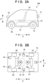
- FIG. 2A illustrates a side surface of the vehicle 100 according to the present embodiment
- FIG. 2B illustrates an internal configuration of the vehicle 100
- an arrow X indicates a front-and-rear direction of the vehicle 100
- F indicates the front
- R indicates the rear
- Arrows Y and Z indicate a width direction (lateral direction) and a vertical direction of the vehicle 100, respectively.
- the vehicle 100 is an electric autonomous vehicle including a traveling unit 12 and using a battery 13 as a main power supply.
- the battery 13 is, for example, a secondary battery such as a lithium ion battery, and the vehicle 100 autonomously travels by the traveling unit 12 by electric power supplied from the battery 13.
- the traveling unit 12 is, for example, a four-wheeled vehicle including a pair of left and right front wheels 20 and a pair of left and right rear wheels 21.
- the traveling unit 12 may be in another form such as a form of a three-wheeled vehicle.
- the vehicle 100 includes a seat 14 for one person or two persons.
- the traveling unit 12 includes a steering mechanism 22.
- the steering mechanism 22 is a mechanism that changes the steering angle of the pair of front wheels 20 using a motor 22a as a drive source. An advancing direction of the vehicle 100 can be changed by changing the steering angle of the pair of front wheels 20.
- the traveling unit 12 also includes a drive mechanism 23.
- the drive mechanism 23 is a mechanism that rotates the pair of rear wheels 21 with a motor 23a as a drive source.
- the vehicle 100 can be moved forward or backward by rotating the pair of rear wheels 21.
- the traveling unit 12 can detect and output physical quantities representing motions of the vehicle 100, such as the traveling speed, acceleration, and steering angle of the vehicle 100, and a rotational acceleration of a body of the vehicle 100.
- the vehicle 100 includes detection units 15 to 17 that detect targets around the vehicle 100.
- the detection units 15 to 17 are a group of external sensors that monitors the surroundings of the vehicle 100, and in the case of the present embodiment, each of the detection units 15 to 17 is an imaging device that captures an image of the surroundings of the vehicle 100 and includes, for example, an optical system such as a lens and an image sensor.
- a radar or a light detection and ranging (LiDAR) can also be used.
- the vehicle 100 can acquire a position (hereinafter, referred to as relative position) of a specific person or a specific target viewed from a coordinate system of the vehicle 100 based on image information obtained by the detection unit.
- the relative position can be indicated as, for example, a position of 1 m on the left and a position of 10 m in front.
- the two detection units 15 are disposed on front portions of the vehicle 100 in a state of being separated from each other in a Y direction, and mainly detect targets in front of the vehicle 100.
- the detection units 16 are disposed on a left side portion and a right side portion of the vehicle 100, respectively, and mainly detect targets on sides of the vehicle 100.
- the detection unit 17 is disposed on a rear portion of the vehicle 100, and mainly detects targets behind the vehicle 100.
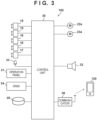
- FIG. 3 is a block diagram of a control system of the vehicle 100.
- the vehicle 100 includes a control unit (ECU) 30.
- the control unit 30 functions as a control apparatus of the vehicle (moving object).
- the control unit 30 includes a processor represented by a central processing unit (CPU), a storage device such as a semiconductor memory, an interface with an external device, and the like.
- the storage device stores a program to be executed by the processor, data used for processing by the processor, and the like.
- a plurality of sets of the processor, the storage device, and the interface may be provided for each function of the vehicle 100 to be capable of communicating with each other.
- the control unit 30 acquires detection results of the detection units 15 to 17, input information of an operation panel 31, voice information input from a voice input device 33, the utterance information from the communication device 120, and the like to execute corresponding processing.
- the control unit 30 performs control of the motors 22a and 23a (traveling control of the traveling unit 12), display control of the operation panel 31, notification to an occupant of the vehicle 100 by voice, and output of information.
- the control unit 30 may further include, as a processor, a graphical processing unit (GPU) or dedicated hardware suitable for executing processing of a machine learning model such as a neural network.
- the control unit 30 executes stop position determination processing according to the present embodiment described later.
- the voice input device 33 can collect a voice of the occupant of the vehicle 100.
- the control unit 30 can recognize the input voice and execute corresponding processing.
- a global navigation satellite system (GNSS) sensor 34 receives a GNSS signal and detects a current position of the vehicle 100.
- GNSS global navigation satellite system
- a storage apparatus 35 is a mass storage device that stores map data and the like including information regarding a traveling road on which the vehicle 100 can travel, landmarks such as buildings, stores, and the like.
- the storage apparatus 35 may also store a program to be executed by the processor, data used for processing by the processor, and the like.
- the storage apparatus 35 may store various parameters (for example, trained parameters of a deep neural network, hyperparameters, and the like) of a machine learning model for voice recognition or image recognition to be executed by the control unit 30.
- the storage apparatus 35 may be provided on a server (not illustrated).
- the communication device 36 is, for example, a communication device that can be connected to the network 140 via wireless communication such as 5th generation mobile communication or Wi-Fi.
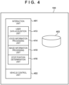
- the present software configuration is implemented by the control unit 30 executing a program stored in a storage medium.
- the software configuration according to the present embodiment includes an interaction unit 401, a vehicle control unit 402, and a database 403.
- the interaction unit 401 performs processing for the voice information (utterance information) transmitted and received to and from the communication device 120, processing for the image information acquired by the detection unit 15 or the like, processing for estimating the stop position, and other processing.
- the vehicle control unit 402 determines a route to the stop position set by the interaction unit 401, and controls each unit of the vehicle along the route.
- the vehicle control unit 402 controls the traveling speed according to a remaining distance. For example, when the remaining distance to the stop position is larger than a predetermined value, the vehicle control unit 402 controls the vehicle to approach the stop position at a first speed that is determined in advance (relatively fast). Furthermore, when the remaining distance is equal to or less than the predetermined value, the vehicle control unit 402 controls the vehicle to approach the stop position at a second speed (first speed > second speed) at which stop control can be quickly performed by safe acceleration/deceleration.
- the database 403 stores various types of data such as the map data including the information regarding the traveling road on which the vehicle 100 can travel, the landmarks such as buildings, the stores, and the like described above, and travel history information of the self-vehicle and other vehicles described above.
- a user data acquisition unit 413 acquires the utterance information and position information transmitted from the communication device 120.
- the user data acquisition unit 413 may store the acquired utterance information and position information in the database 403.
- the utterance information acquired by the user data acquisition unit 413 is input to a trained machine learning model in order to estimate an intention of the user.
- information (instruction information) including the instruction of the user is not limited to the voice information, and may be other information including the intention of the user such as text information.
- a voice information processing unit 414 includes a machine learning model that processes the voice information, and executes processing of an inference stage of the machine learning model.
- the machine learning model of the voice information processing unit 414 recognizes utterance content of the user and estimates an utterance intention of the user by performing computation of a deep learning algorithm using a deep neural network (DNN), for example.
- DNN deep neural network
- a machine learning algorithm separate from the recognition of the utterance content of the user and the estimation of the intention of the user may be used.
- the estimation of the intention of the user may be classification processing of classifying the utterance information into a predetermined intention class.
- the utterance intention class may be defined for each use scene (for example, before boarding, during boarding, and after alighting) in which the user 130 uses the vehicle 100.
- intention classes such as an inquiry, a pick-up request, a greeting, a place instruction, a mark expression, agreement, denial, and asking back may be associated with the use scene of "before boarding".
- intention classes that are at least partially different from those before boarding such as a route instruction, a stop instruction, an acceleration instruction, a deceleration instruction, agreement, denial, and asking back may be associated with the use scene of "during boarding”.
- intention classes that are at least partially different from those before boarding and those during boarding may be associated with the use scene of "after alighting”.
- an utterance such as "Can I ride now?" at a stage before boarding is classified into the intention of "inquiry”.
- an utterance such as "Can you come soon?" is classified into the intention of "pick-up request”.
- utterance information such as "in front of a vending machine” is classified into the intention of "mark expression”.
- a place name or the like included in the utterance information may be identified.
- a place name, a name of a landmark such as a building, a store name, a target name, and the like included in the utterance information are recognized.
- the target may include a pedestrian, a signboard, a sign, equipment installed outdoors such as a vending machine, building components such as a window and an entrance, a road, a vehicle, a two-wheeled vehicle, and the like included in the utterance information.
- the DNN becomes a trained state by performing processing of a training stage, and can perform recognition processing (processing of the inference stage) for utterance information by inputting the utterance information to the trained DNN.
- recognition processing processing of the inference stage
- a recognition result may be received from the server.
- An image information processing unit 415 includes a machine learning model that processes the image information, and the trained machine learning model executes processing of an inference stage.
- the machine learning model of the image information processing unit 415 performs processing of recognizing a target included in the image information by performing computation of a deep learning algorithm using a deep neural network (DNN), for example.
- the target may include a pedestrian, a signboard, a sign, equipment installed outdoors such as a vending machine, building components such as a window and an entrance, a road, a vehicle, a two-wheeled vehicle, and the like included in the image.
- the machine learning model of the image information processing unit 415 can recognize a face of a person, an action (for example, hand gesture) of a person, a shape of a garment, a color of a garment, and the like included in the image information.
- a stop position determination unit 416 cooperates with the voice information processing unit 414 and the image information processing unit 415 described above to execute an operation of the stop position determination processing described later.
- the stop position determination processing will be described later.
- FIGS. 5A to 5H An outline of the stop position determination processing executed in the vehicle 100 will be described with reference to FIGS. 5A to 5H . Note that an operation described with the vehicle 100 as an operation subject in this description is implemented as the control unit 30 of the vehicle 100 executes a program and each unit illustrated in FIG. 4 operates.
- the stop position determination processing when there is a pick-up request from the user, first, the user 130 and the vehicle 100 located at a distant place approach each other to such an extent that the user, the target serving as a mark, or the like can be visually confirmed. Thereafter, the vehicle 100 adjusts the stop position with the user 130 based on the voice information (utterance information) and the image information, and stops at a desired position of the user 130.
- the reason why the stop position can be adjusted in this manner is that the possibility that the user corrects the stop position once determined according to the surrounding situation is considered. Even in a case where there is a possibility that accuracy of voice recognition or image recognition fluctuates according to the surrounding environment such as a state of noise or light, it is possible to easily cope with the case by making the stop position adjustable. As will be described later, in the present embodiment, it is possible to adjust a new stop position while the vehicle 100 moves to a currently set stop position or is stopped, and it is possible to smoothly join at the new stop position.
- FIG. 5A schematically illustrates a state in which the user 130 calls the vehicle 100 stopped at a standby place by an utterance in an area where the vehicle 100 can travel.
- the user 130 transmits utterance information 510 of "Can you come soon?" to the vehicle 100 using the communication device 120.
- the vehicle 100 acquires the utterance information of the user 130 and determines that the utterance intention of the utterance information is "pick-up request"
- the vehicle 100 transmits utterance information 511 of "Yes, I'm coming soon" to the communication device 120.
- the user 130 wants to get on the vehicle 100 while moving toward a vending machine 500 ahead in a moving direction.
- the user 130 transmits utterance information 512 of "I am in a hurry, so come after me” from the communication device 120 to the vehicle 100.
- the vehicle 100 receives the utterance information 512 and recognizes an intention and content of the utterance, the vehicle 100 transmits utterance information 513 of "Understood" to the communication device 120.
- the vehicle 100 acquires position information (for example, GPS information) of the communication device 120 of the user 130 and sets a stop position based on the position of the user 130 and map information. Then, the vehicle 100 calculates a route through which the vehicle moves to the stop position (the position of the user 130 at the present time) from the map information, and moves according to the route.
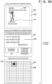
- FIG. 5B schematically illustrates an example of a system status after the vehicle 100 acquires the utterance information 510 of "Can you come soon?" and performs the voice information processing and the like.
- the system status is indicated by visual information understanding 520 indicating a processing result of visual information, language information understanding 521 indicating a processing result of the utterance information, and likelihood 522 of an estimated stop position.
- a display 524 of a recognized target is displayed in captured image information 523.
- information on a subject irrelevant to the description is omitted in order to ensure drawing legibility.
- nothing is described in the image information 523 in the example illustrated in FIG. 5B , but there is actually a subject or the like of a captured background.
- "None" indicating that the target is not recognized is superimposed.
- an utterance intention estimation result 525 of the user 130 is illustrated.
- a horizontal bar graph indicates a probability that the estimated user intention corresponds to a category (pick-up request, place instruction, or the like). This example indicates that there is a high probability that the utterance intention of the utterance information of "Can you come soon?" of the user 130 is the pick-up request.
- the likelihood 522 of the stop position is represented by a map 526 obtained by expressing a region illustrated in FIG. 5A in a mesh, and a color-coded region 527 is a region having a high probability (likelihood) of being estimated as the stop position.
- a blackened region indicates a region having the highest probability as the stop position.
- a region represented by hatching indicates a region having the second highest probability.
- FIG. 5C illustrates a situation in which the vehicle 100 has approached the user 130 to such an extent that the user can be confirmed by the image information.
- the vehicle 100 switches an operation state from a "traveling state based on an absolute position" using the latitude and longitude to a "stop control state based on the relative position” for controlling the stop position using the relative position.
- the position of the moving object or the target from a position based on specific geographic coordinates such as latitude and longitude is referred to as the absolute position.
- the vehicle 100 performs an interaction for confirming whether a person in an image is the user 130. For example, the vehicle 100 transmits utterance information 530 of "I am close. Can you wave your hand?".
- the user 130 transmits utterance information 531 of "Hey, I am here" from the communication device 120 to the vehicle 100 while waving his or her hand.
- the vehicle 100 recognizes the user 130 waving a hand in the image, and transmits, for example, utterance information 532 of "Are you wearing a red garment?" to the communication device 120.
- the user 130 transmits, from the communication device 120 to the vehicle 100, utterance information 533 indicating an agreement that "Yes, I am”.
- FIG. 5D schematically illustrates an example of the system status in a state in which the interaction illustrated in FIG. 5C has progressed between the vehicle 100 and the user 130.
- the image information 523 indicates a recognition result 541 of recognizing a person waving a hand and a recognition result 540 of recognizing a vending machine as a target.
- the language information understanding 521 receives the utterance information 533 of "Yes, I am" of the user 130 and indicates the utterance intention estimation result 525 indicating that there is a high probability that the utterance intention is "agreement”.
- the vehicle 100 calculates the likelihood 522 of the stop position based on the relative position of the user 130 obtained from the recognition result 541 by the image information and the absolute position of the vehicle 100. In this example, since the user 130 has moved, a position of a color-coded region 542 has moved to the right side on the map 526.
- FIG. 5E illustrates an interaction example after the vehicle 100 acquires the position of the user 130 at the relative position.
- the vehicle 100 transmits utterance information 550 of "I will stop in front of you" to the communication device 120.
- the user 130 transmits utterance information 551 of "No, stop over there” to the vehicle 100.
- the user 130 points to the vending machine 500.
- the vehicle 100 recognizes the mark (vending machine) from the image information based on the utterance information 551 (including "over there") and the pointing action of the user 130.
- the vehicle 100 transmits utterance information 552 of "Do you mean the vending machine?" for confirming the mark, and then receives utterance information 553 of "Yes, I do" from the user 130.
- the vehicle 100 sets the position of the vending machine 500 as the stop position, and controls traveling so as to stop at the stop position.
- the vehicle 100 can interact with the user 130 while approaching the initially set stop position to search for the stop position, and can flexibly reset a new stop position even when the new stop position is instructed.
- FIG. 5F schematically illustrates an example of the system status in a state in which the vehicle 100 has processed the utterance information 551 of "No, stop over there" from the user 130.
- the image information 523 indicates a recognition result 561 of recognizing a person pointing a finger and a recognition result 560 of recognizing the vending machine as the target.
- the language information understanding 521 receives the utterance information 551 of "No, stop over there" of the user 130 and indicates the utterance intention estimation result 525 indicating that there is a high probability that the utterance intention is "place instruction”.
- the vehicle 100 calculates the likelihood 522 of the stop position based on the relative position of the vending machine 500 obtained from the recognition results 560 and 561 by the image information and the absolute position of the vehicle 100.
- a position of a color-coded region 562 has moved to the right side (position corresponding to the vending machine 500) on the map 526.
- FIG. 5G illustrates an example of an interaction between the vehicle 100 and the user 130 when the vehicle 100 approaches the position of the vending machine 500.
- the vehicle 100 travels while continuously measuring the relative position of the vending machine appearing in the image information, and transmits utterance information 570 of "Thank you for waiting" to the communication device 120 when approaching the relative position. Furthermore, the vehicle 100 stops at the currently set stop position. When utterance information 571 of "Thank you” from the user 130 is received, the vehicle 100 can determine that dispatch is completed (that is, the relative position is not re-designated).
- FIG. 5H schematically illustrates an example of the system status in a state in which the vehicle 100 has processed the utterance information 571 of "Thank you” from the user 130.
- the image information 523 indicates a recognition result 581 of recognizing a person and a recognition result 580 of recognizing the vending machine as the target.
- the language information understanding 521 receives the utterance information 571 of "Thank you” of the user 130 and indicates the utterance intention estimation result 525 indicating that there is a high probability that the utterance intention is "appreciation”.
- the vehicle 100 calculates the likelihood 522 of the stop position based on the relative position of the vending machine 500 obtained from the recognition result 580 by the image information and the absolute position of the vehicle 100. In this example, since the position of the vending machine 500 is extremely highly likely to be the stop position, a position of a region 582 indicating the high probability indicates the position corresponding to the vending machine 500 on the map 526.
- the vehicle 100 enters a "stopped” state. In this state, when a start command such as the pick-up request is input, the vehicle 100 enters an automated traveling state.
- the automated traveling state roughly includes a "traveling state based on the absolute position", a "stop control state based on the relative position", and a "stop control state".
- the vehicle 100 when the vehicle 100 receives the pick-up request from the user, the vehicle 100 first sets the first stop position based on the absolute position. For example, when the utterance information of the pick-up request includes a mark, the vehicle 100 sets the position of the mark based on the absolute position, and when the utterance information does not include the mark, the vehicle sets the position of the user (GPS position information of the communication device 120) based on the absolute position. Thus, the vehicle 100 transitions to the "traveling state based on the absolute position" in the "automated traveling state” and starts traveling. The vehicle 100 may confirm the stop position with the user 130 while traveling.
- the vehicle 100 transitions to the stop control state when arriving at the stop position. For example, when a predetermined time has elapsed in the stop control state, the vehicle 100 determines that dispatch has been completed, and transitions the state to be "stopped".
- the state transitions to "during a search for the stop position" of the "stop control state based on the relative position".
- the vehicle 100 specifies a user or a mark, and sets the stop position at the relative position of the specified mark or the like. For example, the vehicle 100 transmits utterance information for confirming the stop position to the user 130.
- the vehicle 100 when the vehicle 100 acquires the utterance information 551 of "No, stop over there", the vehicle 100 specifies an indicated object (vending machine 500), sets the relative position of the indicated object to the stop position, and transitions to the "approach/stop control" state.
- the vehicle 100 moves toward the set stop position. At this time, when the vehicle 100 cannot detect a mark serving as the stop position from the image information due to, for example, appearance of an obstacle in front of the vehicle 100, the state of the vehicle 100 is transitioned to "during a search for the stop position". Furthermore, as described above, when the vehicle 100 approaches the stop position during traveling using the relative position, the vehicle 100 may control the traveling speed according to the remaining distance.
- the vehicle 100 stops and enters a stop standby state.
- utterance information for re-designating the relative position is acquired from the user 130 in the stop standby state, the vehicle 100 resets the stop position and returns the state to the "approach/stop control" state.
- the utterance information of the user 130 indicates that the stop position is correct, such as "Thank you"
- the vehicle 100 transitions to the stop control state.
- the vehicle 100 may set a travel control parameter corresponding to each state and control the travel of the vehicle according to the vehicle speed control parameter. For example, for each state of “during a search for the stop position", “approach/stop control”, and “during stop standby", a predetermined target (limit) vehicle speed, target acceleration/deceleration, and lowest state holding time may be held as a table, and the vehicle speed and the like may be controlled according to the transition of the state.
- a predetermined target (limit) vehicle speed, target acceleration/deceleration, and lowest state holding time may be held as a table, and the vehicle speed and the like may be controlled according to the transition of the state.
- a target vehicle speed may be lower than that in the state of "approach/stop control" where the stop position has already been determined because there is a high possibility that a travel route on which the stop position is determined is (newly) changed. That is, the target vehicle speeds for "during a search for the stop position", “approach/stop control", and “during stop standby” may be set to be (A, B, 0) (where A ⁇ B). In this manner, it is possible to realize traveling in accordance with the acceleration/deceleration and the target vehicle speed set for each state along with the transition of the state. Note that the traveling control of the vehicle 100 is not limited to this example. As will be described later, the vehicle speed may be controlled according to a degree of certainty with respect to the stop position.
- the control unit 30 receives the utterance information of the pick-up request and the position information of the user from the communication device 120.
- the utterance information of the pick-up request includes, for example, an utterance such as "Can you come soon?" described above with reference to FIG. 5A .
- the utterance information of the pick-up request may be information including a destination, such as "Can you come soon in front of AAA?".
- the position information of the user is, for example, position information detected by the communication device 120.
- the control unit 30 identifies the destination from the user utterance information of the pick-up request. For example, the control unit 30 may identify "AAA" as the destination from the utterance information like "Can you come soon in front of AAA?".
- the control unit 30 may determine that the destination cannot be identified. Furthermore, the control unit 30 may transmit utterance information, such as asking for a destination, to the communication device 120, and additionally acquire utterance information including the destination.
- control unit 30 determines whether the destination has been identified. For example, when the utterance information of the pick-up request includes a word indicating the destination, the control unit 30 determines that the destination has been identified and advances the processing to S705, and otherwise advances the processing to S704.
- the control unit 30 sets the position of the user as the stop position (when the destination cannot be identified from the utterance information).
- the position information of the user is the absolute position.
- control unit 30 specifies the identified destination position from the map information and sets the specified destination position as the stop position.
- the control unit 30 searches for the name of AAA as the destination from the map information, and sets the position information (for example, latitude/longitude information) obtained by the search as the stop position.
- the position information is the absolute position.
- control unit 30 moves the vehicle 100 to the set stop position. For example, the control unit 30 determines a travel route to the stop position based on the map information, and travels according to the travel route.
- the control unit 30 determines whether the vehicle approaches the stop position. For example, the control unit 30 acquired current position information of the vehicle 100, and determines whether the position information is within a predetermined distance from the latitude and longitude determined as the stop position. When the current position of the vehicle is within the predetermined distance from the stop position, the control unit 30 determines that the vehicle approaches the stop position and advances the processing to S708, and otherwise, the control unit 30 returns the processing to S707 (that is, repeats the determination while the vehicle travels on a route).
- control unit 30 executes stop position adjustment processing using the relative position. Details of the stop position adjustment processing will be described later with reference to FIG. 8 . Upon completion of the stop position adjustment processing using the relative position, the control unit 30 then terminates the series of operations.
- the present processing is realized by the control unit 30 executing a program, similarly to the processing illustrated in FIG. 7 .
- This processing is processing of specifying the relative position of a user or a target as a mark identified by the image information acquired by the detection unit 15 and the like, and controlling traveling to the stop position using the relative position based on the image information.
- this processing generally corresponds to the processing in the "stop control state based on the relative position" described above with reference to FIG. 6 .
- control unit 30 performs object recognition processing on the image acquired by the detection unit 15 and the like, to identify an object region in the image (corresponding to the visual mark).
- control unit 30 determines whether a predetermined number or more of objects are present in the surroundings. For example, the control unit 30 determines whether the number of object regions identified in S801 is the predetermined number or more. When the number of object regions is the predetermined number or more, the control unit 30 advances the processing to S804, and otherwise advances the processing to S803.
- control unit 30 identifies the user from the image information. At this time, the control unit 30 may further identify a user action, such as a hand gesture or a pointing action, of the user. Furthermore, the utterance information for limiting a target person when specifying the user, such as "Can you wave your hand?" or "Are you wearing a red garment?", may be transmitted to the communication device 120.
- the control unit 30 transmits utterance information asking for a mark of the stop position to the communication device 120.
- the mark is identified using the utterance information and the image information by utilizing the utterance information such as transmitting the utterance information asking for a mark of the stop position.
- the control unit 30 may transmit additional utterance information for narrowing down visual marks, for example "Red vending machine?".
- the visual mark cannot be narrowed down to one in a relationship between the utterance information of the user 130 and the image information of the vehicle 100, it is possible to reduce ambiguity of the visual mark by obtaining additional utterance information from the user. This makes it possible to identify a mark with higher accuracy.
- the control unit 30 acquires the utterance information of the user and identifies the mark from the utterance information. At this time, the control unit 30 may further identify a user action, such as a hand gesture or a pointing action, of the user. For example, when the utterance information of the user 130 is "Stop over there”, “over there” which is the instruction word is identified. Furthermore, when the utterance information of the user 130 is "Stop in front of the vending machine", the control unit 30 identifies "vending machine" as the mark.
- a user action such as a hand gesture or a pointing action
- the control unit 30 identifies the mark corresponding to the utterance information identified in S805 from the image information, and specifies the relative position. For example, when “over there" is identified from the utterance information of the user, the control unit 30 recognizes the pointing of the user in the image and identifies an object in that direction as the mark. Furthermore, when the "vending machine" is identified from the utterance information, the control unit 30 identifies a region of the vending machine in the image information. Then, the control unit 30 specifies the relative position of the identified object. As described above, a relative distance is a position viewed from the vehicle 100, and is represented by, for example, 1 m to the left and 10 m to the front.
- a probability distribution indicating a probability corresponding to a visual mark may be calculated for one or more object regions in the image. For example, when the mark included in the utterance information is "vending machine" and there are two or more regions of "vending machine” in the image, the control unit 30 may calculate the probability distribution of the object region further based on a limited linguistic element (for example, "blue") of the utterance content. In this case, for example, when there are a blue vending machine and a red vending machine in the image, a probability distribution in which the probability of the blue vending machine is "0.90" and the probability of the red vending machine is "0.10" may be calculated.
- a limited linguistic element for example, "blue”
- the control unit 30 may further vary the probability distribution according to a relative positional relationship between the target serving as the visual mark and the user 130. If the red vending machine is closer to the current position of the user 130 or the vehicle 100, the control unit 30 may correct the probability distribution so that the probability of the red vending machine is "0.6" and the probability of the blue vending machine is "0.4". It is possible to provide the probability distribution in which the probability increases in the order in which the vending machine can become a candidate when viewed from a direction in which the user approaches.
- the control unit 30 may calculate the probability distribution in consideration of a relative positional relationship as viewed from the vehicle 100. For example, the probability of the region of the vending machine on the left side of the building may be calculated as "0.9", and the probability of the region of the vending machine on the right side of the building may be calculated as "0.1".
- control unit 30 When calculating the probability distribution with respect to the mark, the control unit 30 identifies an object having the highest probability as the mark and specifies the relative position thereof.
- the control unit 30 transmits the utterance information for confirming the stop position to the communication device 120.
- the control unit 30 transmits the utterance information such as "I will stop in front of you" to the communication device 120.
- the control unit 30 receives utterance information regarding confirmation by the user 130 for the utterance information for confirming the stop position. For example, the control unit 30 receives utterance information of "No, go over there".
- the control unit 30 determines whether the received utterance information includes designation of the stop position. That is, the control unit 30 determines whether there is a designation to change the stop position in response to the confirmation of the stop position in S807. For example, when the control unit 30 determines that the utterance information of the user 130 includes designation of a place such as "over there" or "in front of the vending machine", the control unit 30 advances the processing to S805, and otherwise advances the processing to S809. The processing proceeds to S809, for example, when utterance information of "OK" has been received from the user 130.
- step S809 the control unit 30 specifies the relative position of the user or the target as the mark identified by the image information.
- a relative distance is a position viewed from the vehicle 100, and is represented by, for example, 1 m to the left and 10 m to the front.
- the control unit 30 sets the specified relative position as the stop position, and controls traveling to the stop position. At this time, when the mark of the stop position is identified in the image information, the stop position is updated to the position of the mark. As described above, the control unit 30 may control the traveling speed according to the remaining distance to the stop position. Furthermore, the traveling speed may be adjusted according to the degree of certainty of the stop position. For example, when there are a plurality of visual marks (for example, two vending machines) obtained from the utterance information of the user on the image, the control unit 30 can assign the probability distribution to each vending machine according to the utterance of the user and the relative position as described above. In this case, the control unit 30 may use the value of the probability distribution as the degree of certainty.
- the control unit 30 may use the value of the probability distribution as the degree of certainty.
- the control unit 30 reduces the traveling speed more than when the degree of certainty is high. In this manner, when the stop position is highly likely to be changed, it is possible to travel while suppressing the speed of the vehicle and to prepare for the change of the stop position. On the other hand, when the degree of certainty is high, the vehicle can quickly approach the stop position.
- the speed of the vehicle may be linearly changed according to the degree of certainty as follows.
- Final speed (Maximum set speed - Minimum set speed) * Degree of certainty of Stop position + Minimum set speed
- the present invention is not limited to this example, and the traveling speed according to the degree of certainty may be set using a nonlinear function.
- the speed may be changed according to a degree of progress of an interaction between the user and the vehicle.
- control unit 30 may acquire a set of a stop position and a distribution of the degrees of certainty, and obtain the final speed by using an evaluation function.
- the following optimization problem may be considered to obtain a target speed at which the following cost within a predicted time is minimized.
- control unit 30 determines whether there is re-designation of the stop position (for example, reception of utterance information for designating the stop position from the user 130). When the control unit 30 determines that there is re-designation of the stop position, the control unit 30 advances the processing to S805, and otherwise advances the processing to S812. In S812, the control unit 30 determines whether a distance to the stop position has approached within a predetermined distance. The control unit 30 advances the processing to S813 when the distance to the stop position has approached within the predetermined distance, and otherwise returns the processing to S811.
- control unit 30 since the stop position is not re-designated and the vehicle approaches the stop position, the vehicle decelerates and stops at the stop position. At this time, the control unit 30 transmits utterance information (for example, "Thank you for waiting") notifying of arrival to the communication device 120. Thereafter, the control unit 30 ends the stop position adjustment processing using the relative position, and returns to a calling-source processing. Then, the control unit 30 also ends the series of processes illustrated in FIG. 7 .
- the vehicle 100 first approaches to such an extent that the user, the target serving as the mark, or the like can be visually confirmed using the absolute position, and then stops at a desired position of the user 130 by adjusting the stop position with the user 130 based on the voice information (utterance information) and the image information. In this manner, the stop position of the vehicle (moving object) can be flexibly adjusted between the user and the vehicle (moving object).
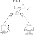
- an information processing system 900 includes a vehicle 910, the communication device 120, and a server 901.
- the information processing system 900 includes the vehicle 910, the server 901, and the communication device 120.
- the server 901 includes one or more server devices, and is capable of acquiring, via the network 111, information on the vehicle transmitted from the vehicle 910, and the utterance information and the position information transmitted from the communication device 120, and controlling traveling of the vehicle 910.
- the server can generally use more abundant calculation resources than the vehicle and the like. Furthermore, it is possible to collect training data under a wide variety of situations by receiving and accumulating data on images captured by various vehicles, so that it is possible to perform training in response to a wider variety of circumstances.
- the utterance information of the user is transmitted from the communication device 120 to the server 901. Furthermore, the server 901 acquires image information captured by the vehicle 910 as part of floating data of the vehicle 910 together with position information and the like via the network 140. For example, after the server 901 performs processing corresponding to S701 to S705 of the stop position determination processing described above, the server 901 transmits a control amount such as the traveling speed to the vehicle 910 in S706. The vehicle 910 travels (continues traveling) according to the received control amount. Subsequently, the server 901 executes processing corresponding to S707 and S708.
- the server 901 executes processing corresponding to S801 to S809 also in the stop position adjustment processing using the relative position, and transmits the control amount such as the traveling speed to the vehicle 910 in S810.
- the vehicle 910 travels (continues traveling) according to the received control amount.
- the server 901 executes processing corresponding to S811 to S813.
- These processing executed by the server 901 are implemented by a processor (not illustrated) included in the server 901 executing a program stored in a storage medium (not illustrated) included in the server 901.
- the configuration of the vehicle 910 may be the same as that of the vehicle 100 except that the control unit 30 does not execute the stop position determination processing and the vehicle is caused to travel according to the control amount from the server 901.
- the server 901 causes the vehicle to approach to such an extent that the user, the target serving as the mark, or the like can be visually confirmed using the absolute position, and then stops the vehicle at a desired position of the user 130 by adjusting the stop position with the user 130 based on the voice information (utterance information) and the image information. In this manner, the stop position of the vehicle (moving object) can be flexibly adjusted between the user and the vehicle (moving object).
- the stop position of the vehicle (moving object) is adjusted between the user who is going to join and the vehicle (moving object); however, the application of the present invention is not limited thereto.
- the present invention may be applied to a case where the user instructs the stop position based on the target serving as the mark while riding on the vehicle (moving object).
- the moving object determines the stop position while responding "Is that red vending machine?" or the like in response to the utterance information (instruction information) of the user "stop in front of the vending machine over there". Thereafter, it is conceivable that the moving object adjusts the stop position based on utterance information (instruction information) such as "Stop at the convenience store over there" from the user.
Landscapes
- Engineering & Computer Science (AREA)
- Physics & Mathematics (AREA)
- General Physics & Mathematics (AREA)
- Business, Economics & Management (AREA)
- Theoretical Computer Science (AREA)
- Human Resources & Organizations (AREA)
- Radar, Positioning & Navigation (AREA)
- Remote Sensing (AREA)
- Economics (AREA)
- Strategic Management (AREA)
- Multimedia (AREA)
- Automation & Control Theory (AREA)
- Human Computer Interaction (AREA)
- Entrepreneurship & Innovation (AREA)
- Marketing (AREA)
- Mathematical Physics (AREA)
- Tourism & Hospitality (AREA)
- General Business, Economics & Management (AREA)
- Aviation & Aerospace Engineering (AREA)
- Operations Research (AREA)
- General Health & Medical Sciences (AREA)
- Health & Medical Sciences (AREA)
- Atmospheric Sciences (AREA)
- Life Sciences & Earth Sciences (AREA)
- General Engineering & Computer Science (AREA)
- Quality & Reliability (AREA)
- Development Economics (AREA)
- Software Systems (AREA)
- Game Theory and Decision Science (AREA)
- Computing Systems (AREA)
- Educational Administration (AREA)
- Data Mining & Analysis (AREA)
- Medical Informatics (AREA)
- Analytical Chemistry (AREA)
- Computer Vision & Pattern Recognition (AREA)
- Artificial Intelligence (AREA)
- Evolutionary Computation (AREA)
- Databases & Information Systems (AREA)
- Chemical & Material Sciences (AREA)
- Primary Health Care (AREA)
Abstract
Description
- The present invention relates to a moving object control apparatus, a method for controlling a moving object, a moving object, an information processing method, and a program.
- In recent years, an electric vehicle called an ultra-compact mobility vehicle (also referred to as a micro mobility vehicle) having a riding capacity of about one or two persons is known, and is expected to spread as an easy movement mechanism.
- In order to use the ultra-compact mobility vehicle that travels by automated driving as the easy movement mechanism, it is desirable that the ultra-compact mobility vehicle stops at a suitable place where a user can easily ride.
PTL 1 discloses a technique in which, when the user coming out of a house is allowed to ride in an automated driving vehicle, a distance for the user to walk to a riding position is made as short as possible to prevent the user from feeling inconvenience. Furthermore, PTL 2 discloses a technique in which a vehicle traveling by automated driving determines a stop position, when recognizing that an occupant of a self-vehicle is present in a boarding and alighting area, to be a position at which a distance between the self-vehicle and the occupant in the area is within several meters, and travels to the stop position. -
- PTL 1:
Japanese Patent Laid-Open No. 2019-91216 - PTL 2:
Japanese Patent Laid-Open No. 2020-142720 - Incidentally, in a case where the user uses the ultra-compact mobility vehicle, a use case is conceivable in which the ultra-compact mobility vehicle and the user dynamically adjust the stop position of the mobility while moving. Such a use case is effective in a case where joining at a scheduled position is difficult due to congestion, restriction, or the like, a case where the stop position is to be finely adjusted, and the like. In the above-described related art, there is no consideration regarding the use case in which the vehicle and the user dynamically adjusts the stop position of the vehicle while moving.
- The present invention has been made in view of the above problems, and an object thereof is to realize a technique capable of flexibly adjusting a stop position of a moving object (for example, a vehicle) between a user and the moving object.
- According to the preset invention, a moving object control apparatus that adjusts a stop position of a moving object based on an instruction of a user, the moving object control apparatus characterized by comprising: instruction acquisition means for acquiring instruction information of the user; image acquisition means for acquiring a captured image captured in the moving object; determination means for determining a stop position of the moving object; and control means for controlling traveling of the moving object to cause the moving object to travel toward the determined stop position, characterized in that the determination means (i) determines a first stop position using position information of a communication device used by the user or position information corresponding to a destination included in first instruction information of the user, and (ii) determines a second stop position based on second instruction information of the user and a region of a predetermined target identified in the captured image in response to a position of the moving object falling within a predetermined distance from the first stop position by traveling of the moving object is provided.
- According to the present invention, it is possible to flexibly adjust the stop position of the moving object between the user and the moving object.
-
-
FIG. 1 is a diagram illustrating an example of an information processing system according to an embodiment of the present invention. -
FIG. 2A is a block diagram (1) illustrating a hardware configuration example of a vehicle according to the present embodiment. -
FIG. 2B is a block diagram (2) illustrating the hardware configuration example of the vehicle according to the present embodiment. -
FIG. 3 is a block diagram illustrating a functional configuration example of the vehicle according to the present embodiment. -
FIG. 4 is a block diagram illustrating an example of a functional configuration implemented by a control unit according to the present embodiment. -
FIG. 5A is a diagram (1) illustrating determination of a stop position of the vehicle using an utterance and an image according to the present embodiment. -
FIG. 5B is a diagram (2) illustrating determination of the stop position of the vehicle using the utterance and the image according to the present embodiment. -
FIG. 5C is a diagram (3) illustrating determination of the stop position of the vehicle using the utterance and the image according to the present embodiment. -
FIG. 5D is a diagram (4) illustrating determination of the stop position of the vehicle using the utterance and the image according to the present embodiment. -
FIG. 5E is a diagram (5) illustrating determination of the stop position of the vehicle using the utterance and the image according to the present embodiment. -
FIG. 5F is a diagram (6) illustrating determination of the stop position of the vehicle using the utterance and the image according to the present embodiment. -
FIG. 5G is a diagram (7) illustrating determination of the stop position of the vehicle using the utterance and the image according to the present embodiment. -
FIG. 5H is a diagram (8) illustrating determination of the stop position of the vehicle using the utterance and the image according to the present embodiment. -
FIG. 6 is a diagram illustrating a state transition of vehicle control in response to an instruction of the stop position according to the present embodiment. -
FIG. 7 is a flowchart illustrating a series of operations of stop position determination processing according to the present embodiment. -
FIG. 8 is a flowchart illustrating a series of operations of stop position adjustment processing using a relative position according to the present embodiment. -
FIG. 9 is a diagram illustrating an example of an information processing system according to another embodiment. - Hereinafter, embodiments will be described in detail with reference to the attached drawings. Note, the following embodiments are not intended to limit the scope of the claimed invention, and limitation is not made to an invention that requires a combination of all features described in the embodiments. Two or more of the multiple features described in the embodiments may be combined as appropriate. Furthermore, the same reference numerals are given to the same or similar configurations, and redundant description thereof is omitted.
- A configuration of an
information processing system 10 according to the present embodiment will be described with reference toFIG. 1 . Theinformation processing system 10 includes avehicle 100 and acommunication device 120. - The
vehicle 100 is an example of a moving object, and is, for example, an ultra-compact mobility vehicle that is equipped with a battery and moves mainly by the power of a motor. The ultra-compact mobility vehicle is an ultra-compact vehicle that is more compact than a general automobile and has a riding capacity of about one or two persons. The ultra-compact mobility vehicle may be able to travel on roadways or sidewalks. In the present embodiment, thevehicle 100 is, for example, a four-wheeled vehicle. Note that the present embodiment is applicable not only to vehicles but also to other moving objects. The moving object is not limited to the vehicle, and may include a small mobility such as traveling in parallel with a walking user to carry baggage or lead a person, or may include another moving object (such as a walking robot) capable of autonomous movement. - The
vehicle 100 is connected to anetwork 140 via wireless communication such as 5th generation mobile communication, road-to-vehicle communication, or Wi-Fi. Thevehicle 100 measures states inside and outside the vehicle (such as a vehicle position, a traveling state, or a target of a surrounding object) by various sensors and accumulates measured data. The data collected and transmitted as described above is also generally referred to as floating data, probe data, traffic information, or the like. Thevehicle 100 may transmit the accumulated data to a server (not illustrated). When information on the vehicle is transmitted to the server, the information is transmitted at regular intervals or in response to an occurrence of a specific event. Thevehicle 100 can travel by automated driving even when auser 130 does not ride the vehicle. Thevehicle 100 can start traveling from a first stop position toward a position where theuser 130 rides the vehicle in accordance with utterance information from thecommunication device 120 or the like. As will be described later, thevehicle 100 acquires the utterance information of the user transmitted from thecommunication device 120 via a network 111 and transmits the utterance information to thecommunication device 120 to adjust the stop position with the user. Thevehicle 100 stops the vehicle at the adjusted stop position to allow the user to ride the vehicle. - The
communication device 120 is, for example, a smartphone, but is not limited thereto, and may be an earphone type communication terminal, a personal computer, a tablet terminal, a game machine, or the like. Thecommunication device 120 is connected to thenetwork 140 via wireless communication such as 5th generation mobile communication or Wi-Fi. - The network 111 includes, for example, a communication network such as the Internet or a mobile phone network, and transmits information between the
vehicle 100, thecommunication device 120, a server (not illustrated), and the like. - In the
information processing system 10, in a case where theuser 130 and thevehicle 100 at distant places approach each other to such an extent that a target or the like (serving as a visual mark) can be visually confirmed, the stop position is adjusted using the utterance information and image information captured by thevehicle 100. - Before the
user 130 and thevehicle 100 approach each other to the extent that the target or the like can be visually confirmed, first, thevehicle 100 moves a current position of the user on a map or a position of a destination obtained from the utterance information of the user on the map as the stop position. Then, when thevehicle 100 approaches the stop position, the user is identified, or the utterance information (for example, "Is there a store nearby?") asking for a place related to the visual mark is transmitted to thecommunication device 120. As a result, thevehicle 100 can move toward the position of the user in a case where the user can be found (identified) from the image information, or can move toward a mark obtained from the utterance information even in a situation where it is difficult to identify the user. - The place related to the visual mark includes, for example, a name of a target that can be identified from an image. The
vehicle 100 receives, from thecommunication device 120, the utterance information (for example, "Stop in front of the vending machine") including the place related to the visual mark. Then, thevehicle 100 identifies the target as the mark from the image information and moves to the front of a place of the mark. - Next, a configuration of the
vehicle 100 as an example of the vehicle according to the present embodiment will be described with reference toFIGS. 2A and 2B . -
FIG. 2A illustrates a side surface of thevehicle 100 according to the present embodiment, andFIG. 2B illustrates an internal configuration of thevehicle 100. In the drawings, an arrow X indicates a front-and-rear direction of thevehicle 100, F indicates the front, and R indicates the rear. Arrows Y and Z indicate a width direction (lateral direction) and a vertical direction of thevehicle 100, respectively. - The
vehicle 100 is an electric autonomous vehicle including a travelingunit 12 and using abattery 13 as a main power supply. Thebattery 13 is, for example, a secondary battery such as a lithium ion battery, and thevehicle 100 autonomously travels by the travelingunit 12 by electric power supplied from thebattery 13. The travelingunit 12 is, for example, a four-wheeled vehicle including a pair of left and rightfront wheels 20 and a pair of left and rightrear wheels 21. The travelingunit 12 may be in another form such as a form of a three-wheeled vehicle. Thevehicle 100 includes aseat 14 for one person or two persons. - The traveling
unit 12 includes asteering mechanism 22. Thesteering mechanism 22 is a mechanism that changes the steering angle of the pair offront wheels 20 using amotor 22a as a drive source. An advancing direction of thevehicle 100 can be changed by changing the steering angle of the pair offront wheels 20. The travelingunit 12 also includes adrive mechanism 23. Thedrive mechanism 23 is a mechanism that rotates the pair ofrear wheels 21 with amotor 23a as a drive source. Thevehicle 100 can be moved forward or backward by rotating the pair ofrear wheels 21. The travelingunit 12 can detect and output physical quantities representing motions of thevehicle 100, such as the traveling speed, acceleration, and steering angle of thevehicle 100, and a rotational acceleration of a body of thevehicle 100. - The
vehicle 100 includesdetection units 15 to 17 that detect targets around thevehicle 100. Thedetection units 15 to 17 are a group of external sensors that monitors the surroundings of thevehicle 100, and in the case of the present embodiment, each of thedetection units 15 to 17 is an imaging device that captures an image of the surroundings of thevehicle 100 and includes, for example, an optical system such as a lens and an image sensor. In thevehicle 100, in addition to the imaging device, a radar or a light detection and ranging (LiDAR) can also be used. Thevehicle 100 can acquire a position (hereinafter, referred to as relative position) of a specific person or a specific target viewed from a coordinate system of thevehicle 100 based on image information obtained by the detection unit. The relative position can be indicated as, for example, a position of 1 m on the left and a position of 10 m in front. - The two
detection units 15 are disposed on front portions of thevehicle 100 in a state of being separated from each other in a Y direction, and mainly detect targets in front of thevehicle 100. Thedetection units 16 are disposed on a left side portion and a right side portion of thevehicle 100, respectively, and mainly detect targets on sides of thevehicle 100. Thedetection unit 17 is disposed on a rear portion of thevehicle 100, and mainly detects targets behind thevehicle 100. -
FIG. 3 is a block diagram of a control system of thevehicle 100. Thevehicle 100 includes a control unit (ECU) 30. Thecontrol unit 30 functions as a control apparatus of the vehicle (moving object). Thecontrol unit 30 includes a processor represented by a central processing unit (CPU), a storage device such as a semiconductor memory, an interface with an external device, and the like. The storage device stores a program to be executed by the processor, data used for processing by the processor, and the like. A plurality of sets of the processor, the storage device, and the interface may be provided for each function of thevehicle 100 to be capable of communicating with each other. - The
control unit 30 acquires detection results of thedetection units 15 to 17, input information of anoperation panel 31, voice information input from avoice input device 33, the utterance information from thecommunication device 120, and the like to execute corresponding processing. Thecontrol unit 30 performs control of themotors operation panel 31, notification to an occupant of thevehicle 100 by voice, and output of information. In addition to the CPU, thecontrol unit 30 may further include, as a processor, a graphical processing unit (GPU) or dedicated hardware suitable for executing processing of a machine learning model such as a neural network. In addition, thecontrol unit 30 executes stop position determination processing according to the present embodiment described later. - The
voice input device 33 can collect a voice of the occupant of thevehicle 100. Thecontrol unit 30 can recognize the input voice and execute corresponding processing. A global navigation satellite system (GNSS)sensor 34 receives a GNSS signal and detects a current position of thevehicle 100. - A
storage apparatus 35 is a mass storage device that stores map data and the like including information regarding a traveling road on which thevehicle 100 can travel, landmarks such as buildings, stores, and the like. Thestorage apparatus 35 may also store a program to be executed by the processor, data used for processing by the processor, and the like. Thestorage apparatus 35 may store various parameters (for example, trained parameters of a deep neural network, hyperparameters, and the like) of a machine learning model for voice recognition or image recognition to be executed by thecontrol unit 30. Furthermore, thestorage apparatus 35 may be provided on a server (not illustrated). - The
communication device 36 is, for example, a communication device that can be connected to thenetwork 140 via wireless communication such as 5th generation mobile communication or Wi-Fi. - Next, a software configuration for the stop position determination processing in the
control unit 30 will be described with reference toFIG. 4 . The present software configuration is implemented by thecontrol unit 30 executing a program stored in a storage medium. - The software configuration according to the present embodiment includes an
interaction unit 401, avehicle control unit 402, and adatabase 403. Theinteraction unit 401 performs processing for the voice information (utterance information) transmitted and received to and from thecommunication device 120, processing for the image information acquired by thedetection unit 15 or the like, processing for estimating the stop position, and other processing. - The
vehicle control unit 402, for example, determines a route to the stop position set by theinteraction unit 401, and controls each unit of the vehicle along the route. Although details will be described later, when thevehicle 100 approaches the stop position during traveling using the relative position, thevehicle control unit 402 controls the traveling speed according to a remaining distance. For example, when the remaining distance to the stop position is larger than a predetermined value, thevehicle control unit 402 controls the vehicle to approach the stop position at a first speed that is determined in advance (relatively fast). Furthermore, when the remaining distance is equal to or less than the predetermined value, thevehicle control unit 402 controls the vehicle to approach the stop position at a second speed (first speed > second speed) at which stop control can be quickly performed by safe acceleration/deceleration. - The
database 403 stores various types of data such as the map data including the information regarding the traveling road on which thevehicle 100 can travel, the landmarks such as buildings, the stores, and the like described above, and travel history information of the self-vehicle and other vehicles described above. - A user
data acquisition unit 413 acquires the utterance information and position information transmitted from thecommunication device 120. The userdata acquisition unit 413 may store the acquired utterance information and position information in thedatabase 403. As will be described later, the utterance information acquired by the userdata acquisition unit 413 is input to a trained machine learning model in order to estimate an intention of the user. Note that, in the following description, a case where an instruction of the user is acquired based on the utterance information will be described as an example. However, information (instruction information) including the instruction of the user is not limited to the voice information, and may be other information including the intention of the user such as text information. - A voice
information processing unit 414 includes a machine learning model that processes the voice information, and executes processing of an inference stage of the machine learning model. The machine learning model of the voiceinformation processing unit 414 recognizes utterance content of the user and estimates an utterance intention of the user by performing computation of a deep learning algorithm using a deep neural network (DNN), for example. A machine learning algorithm separate from the recognition of the utterance content of the user and the estimation of the intention of the user may be used. - The estimation of the intention of the user may be classification processing of classifying the utterance information into a predetermined intention class. The utterance intention class may be defined for each use scene (for example, before boarding, during boarding, and after alighting) in which the
user 130 uses thevehicle 100. By defining the intention class for each use scene, the number of classifications in intention recognition is limited, and recognition accuracy can be improved. For example, intention classes such as an inquiry, a pick-up request, a greeting, a place instruction, a mark expression, agreement, denial, and asking back may be associated with the use scene of "before boarding". Furthermore, for example, intention classes that are at least partially different from those before boarding, such as a route instruction, a stop instruction, an acceleration instruction, a deceleration instruction, agreement, denial, and asking back may be associated with the use scene of "during boarding". Similarly, intention classes that are at least partially different from those before boarding and those during boarding may be associated with the use scene of "after alighting". As an example of estimation of the intention class, an utterance such as "Can I ride now?" at a stage before boarding is classified into the intention of "inquiry". Furthermore, an utterance such as "Can you come soon?" is classified into the intention of "pick-up request". In addition, utterance information such as "in front of a vending machine" is classified into the intention of "mark expression". - In the recognition of the utterance content of the user, for example, when the utterance intention of the user is the place instruction, a place name or the like included in the utterance information may be identified. In the recognition of the utterance content of the user, for example, a place name, a name of a landmark such as a building, a store name, a target name, and the like included in the utterance information are recognized. The target may include a pedestrian, a signboard, a sign, equipment installed outdoors such as a vending machine, building components such as a window and an entrance, a road, a vehicle, a two-wheeled vehicle, and the like included in the utterance information.
- The DNN becomes a trained state by performing processing of a training stage, and can perform recognition processing (processing of the inference stage) for utterance information by inputting the utterance information to the trained DNN. Note that, in the present embodiment, a case where the
vehicle 100 executes voice recognition processing will be described as an example, but the voice recognition processing may be executed by a server (not illustrated), and a recognition result may be received from the server. - An image
information processing unit 415 includes a machine learning model that processes the image information, and the trained machine learning model executes processing of an inference stage. The machine learning model of the imageinformation processing unit 415 performs processing of recognizing a target included in the image information by performing computation of a deep learning algorithm using a deep neural network (DNN), for example. The target may include a pedestrian, a signboard, a sign, equipment installed outdoors such as a vending machine, building components such as a window and an entrance, a road, a vehicle, a two-wheeled vehicle, and the like included in the image. In addition, the machine learning model of the imageinformation processing unit 415 can recognize a face of a person, an action (for example, hand gesture) of a person, a shape of a garment, a color of a garment, and the like included in the image information. - A stop
position determination unit 416 cooperates with the voiceinformation processing unit 414 and the imageinformation processing unit 415 described above to execute an operation of the stop position determination processing described later. The stop position determination processing will be described later. - An outline of the stop position determination processing executed in the
vehicle 100 will be described with reference toFIGS. 5A to 5H . Note that an operation described with thevehicle 100 as an operation subject in this description is implemented as thecontrol unit 30 of thevehicle 100 executes a program and each unit illustrated inFIG. 4 operates. - In the stop position determination processing, when there is a pick-up request from the user, first, the
user 130 and thevehicle 100 located at a distant place approach each other to such an extent that the user, the target serving as a mark, or the like can be visually confirmed. Thereafter, thevehicle 100 adjusts the stop position with theuser 130 based on the voice information (utterance information) and the image information, and stops at a desired position of theuser 130. The reason why the stop position can be adjusted in this manner is that the possibility that the user corrects the stop position once determined according to the surrounding situation is considered. Even in a case where there is a possibility that accuracy of voice recognition or image recognition fluctuates according to the surrounding environment such as a state of noise or light, it is possible to easily cope with the case by making the stop position adjustable. As will be described later, in the present embodiment, it is possible to adjust a new stop position while thevehicle 100 moves to a currently set stop position or is stopped, and it is possible to smoothly join at the new stop position. -
FIG. 5A schematically illustrates a state in which theuser 130 calls thevehicle 100 stopped at a standby place by an utterance in an area where thevehicle 100 can travel. First, theuser 130 transmitsutterance information 510 of "Can you come soon?" to thevehicle 100 using thecommunication device 120. When thevehicle 100 acquires the utterance information of theuser 130 and determines that the utterance intention of the utterance information is "pick-up request", thevehicle 100 transmitsutterance information 511 of "Yes, I'm coming soon" to thecommunication device 120. In the vicinity of the current position of theuser 130, for example, there is a region where the vehicle cannot be stopped. Furthermore, theuser 130 wants to get on thevehicle 100 while moving toward avending machine 500 ahead in a moving direction. Thus, theuser 130 transmitsutterance information 512 of "I am in a hurry, so come after me" from thecommunication device 120 to thevehicle 100. When thevehicle 100 receives theutterance information 512 and recognizes an intention and content of the utterance, thevehicle 100 transmitsutterance information 513 of "Understood" to thecommunication device 120. At this time, since designation of a destination is not included in the utterance information of the user, thevehicle 100 acquires position information (for example, GPS information) of thecommunication device 120 of theuser 130 and sets a stop position based on the position of theuser 130 and map information. Then, thevehicle 100 calculates a route through which the vehicle moves to the stop position (the position of theuser 130 at the present time) from the map information, and moves according to the route. -
FIG. 5B schematically illustrates an example of a system status after thevehicle 100 acquires theutterance information 510 of "Can you come soon?" and performs the voice information processing and the like. As an example, the system status is indicated by visual information understanding 520 indicating a processing result of visual information, language information understanding 521 indicating a processing result of the utterance information, andlikelihood 522 of an estimated stop position. - In the visual information understanding 520, a
display 524 of a recognized target is displayed in capturedimage information 523. Note that, in the present description, information on a subject irrelevant to the description is omitted in order to ensure drawing legibility. Thus, nothing is described in theimage information 523 in the example illustrated inFIG. 5B , but there is actually a subject or the like of a captured background. In the example illustrated inFIG. 5B , "None" indicating that the target is not recognized is superimposed. - In the language information understanding 521, an utterance
intention estimation result 525 of theuser 130 is illustrated. A horizontal bar graph indicates a probability that the estimated user intention corresponds to a category (pick-up request, place instruction, or the like). This example indicates that there is a high probability that the utterance intention of the utterance information of "Can you come soon?" of theuser 130 is the pick-up request. - The
likelihood 522 of the stop position is represented by amap 526 obtained by expressing a region illustrated inFIG. 5A in a mesh, and a color-codedregion 527 is a region having a high probability (likelihood) of being estimated as the stop position. A blackened region indicates a region having the highest probability as the stop position. Furthermore, a region represented by hatching indicates a region having the second highest probability. -
FIG. 5C illustrates a situation in which thevehicle 100 has approached theuser 130 to such an extent that the user can be confirmed by the image information. In this situation, thevehicle 100 switches an operation state from a "traveling state based on an absolute position" using the latitude and longitude to a "stop control state based on the relative position" for controlling the stop position using the relative position. Here, the position of the moving object or the target from a position based on specific geographic coordinates such as latitude and longitude is referred to as the absolute position. Since the relative position is determined using the image information, thevehicle 100 performs an interaction for confirming whether a person in an image is theuser 130. For example, thevehicle 100 transmitsutterance information 530 of "I am close. Can you wave your hand?". Theuser 130 transmitsutterance information 531 of "Hey, I am here" from thecommunication device 120 to thevehicle 100 while waving his or her hand. Thevehicle 100 recognizes theuser 130 waving a hand in the image, and transmits, for example,utterance information 532 of "Are you wearing a red garment?" to thecommunication device 120. In response, theuser 130 transmits, from thecommunication device 120 to thevehicle 100,utterance information 533 indicating an agreement that "Yes, I am". -
FIG. 5D schematically illustrates an example of the system status in a state in which the interaction illustrated inFIG. 5C has progressed between thevehicle 100 and theuser 130. Theimage information 523 indicates arecognition result 541 of recognizing a person waving a hand and arecognition result 540 of recognizing a vending machine as a target. Furthermore, the language information understanding 521 receives theutterance information 533 of "Yes, I am" of theuser 130 and indicates the utteranceintention estimation result 525 indicating that there is a high probability that the utterance intention is "agreement". In addition, thevehicle 100 calculates thelikelihood 522 of the stop position based on the relative position of theuser 130 obtained from therecognition result 541 by the image information and the absolute position of thevehicle 100. In this example, since theuser 130 has moved, a position of a color-codedregion 542 has moved to the right side on themap 526. -
FIG. 5E illustrates an interaction example after thevehicle 100 acquires the position of theuser 130 at the relative position. Thevehicle 100 transmitsutterance information 550 of "I will stop in front of you" to thecommunication device 120. In response, since the user desires to ride in another place, theuser 130 transmitsutterance information 551 of "No, stop over there" to thevehicle 100. At this time, theuser 130 points to thevending machine 500. Thevehicle 100 recognizes the mark (vending machine) from the image information based on the utterance information 551 (including "over there") and the pointing action of theuser 130. Then, thevehicle 100 transmitsutterance information 552 of "Do you mean the vending machine?" for confirming the mark, and then receivesutterance information 553 of "Yes, I do" from theuser 130. Through the interaction and the recognition processing, thevehicle 100 sets the position of thevending machine 500 as the stop position, and controls traveling so as to stop at the stop position. As described above, thevehicle 100 can interact with theuser 130 while approaching the initially set stop position to search for the stop position, and can flexibly reset a new stop position even when the new stop position is instructed. -
FIG. 5F schematically illustrates an example of the system status in a state in which thevehicle 100 has processed theutterance information 551 of "No, stop over there" from theuser 130. Theimage information 523 indicates arecognition result 561 of recognizing a person pointing a finger and a recognition result 560 of recognizing the vending machine as the target. Furthermore, the language information understanding 521 receives theutterance information 551 of "No, stop over there" of theuser 130 and indicates the utteranceintention estimation result 525 indicating that there is a high probability that the utterance intention is "place instruction". In addition, thevehicle 100 calculates thelikelihood 522 of the stop position based on the relative position of thevending machine 500 obtained from the recognition results 560 and 561 by the image information and the absolute position of thevehicle 100. In this example, since the position of thevending machine 500 is highly likely to be the stop position, a position of a color-codedregion 562 has moved to the right side (position corresponding to the vending machine 500) on themap 526. -
FIG. 5G illustrates an example of an interaction between thevehicle 100 and theuser 130 when thevehicle 100 approaches the position of thevending machine 500. Thevehicle 100 travels while continuously measuring the relative position of the vending machine appearing in the image information, and transmitsutterance information 570 of "Thank you for waiting" to thecommunication device 120 when approaching the relative position. Furthermore, thevehicle 100 stops at the currently set stop position. Whenutterance information 571 of "Thank you" from theuser 130 is received, thevehicle 100 can determine that dispatch is completed (that is, the relative position is not re-designated). -
FIG. 5H schematically illustrates an example of the system status in a state in which thevehicle 100 has processed theutterance information 571 of "Thank you" from theuser 130. Theimage information 523 indicates arecognition result 581 of recognizing a person and arecognition result 580 of recognizing the vending machine as the target. Furthermore, the language information understanding 521 receives theutterance information 571 of "Thank you" of theuser 130 and indicates the utteranceintention estimation result 525 indicating that there is a high probability that the utterance intention is "appreciation". In addition, thevehicle 100 calculates thelikelihood 522 of the stop position based on the relative position of thevending machine 500 obtained from therecognition result 580 by the image information and the absolute position of thevehicle 100. In this example, since the position of thevending machine 500 is extremely highly likely to be the stop position, a position of aregion 582 indicating the high probability indicates the position corresponding to thevending machine 500 on themap 526. - Next, a state transition of traveling system control of the
vehicle 100 according to an instruction of a stop position will be described with reference toFIG. 6 . First, when the state transition of thevehicle 100 is started, thevehicle 100 enters a "stopped" state. In this state, when a start command such as the pick-up request is input, thevehicle 100 enters an automated traveling state. The automated traveling state roughly includes a "traveling state based on the absolute position", a "stop control state based on the relative position", and a "stop control state". - In the "traveling state based on the absolute position", as described above, when the
vehicle 100 receives the pick-up request from the user, thevehicle 100 first sets the first stop position based on the absolute position. For example, when the utterance information of the pick-up request includes a mark, thevehicle 100 sets the position of the mark based on the absolute position, and when the utterance information does not include the mark, the vehicle sets the position of the user (GPS position information of the communication device 120) based on the absolute position. Thus, thevehicle 100 transitions to the "traveling state based on the absolute position" in the "automated traveling state" and starts traveling. Thevehicle 100 may confirm the stop position with theuser 130 while traveling. When the utterance information of theuser 130 indicates that the stop position is the current stop position, thevehicle 100 transitions to the stop control state when arriving at the stop position. For example, when a predetermined time has elapsed in the stop control state, thevehicle 100 determines that dispatch has been completed, and transitions the state to be "stopped". - When the
vehicle 100 approaches the stop position (set at the absolute position) to such an extent that the user, a target as a mark, or the like can be visually confirmed, the state transitions to "during a search for the stop position" of the "stop control state based on the relative position". During the search for the stop position, thevehicle 100 specifies a user or a mark, and sets the stop position at the relative position of the specified mark or the like. For example, thevehicle 100 transmits utterance information for confirming the stop position to theuser 130. As in the above-described example, when thevehicle 100 acquires theutterance information 551 of "No, stop over there", thevehicle 100 specifies an indicated object (vending machine 500), sets the relative position of the indicated object to the stop position, and transitions to the "approach/stop control" state. - In the "approach/stop control" state, the
vehicle 100 moves toward the set stop position. At this time, when thevehicle 100 cannot detect a mark serving as the stop position from the image information due to, for example, appearance of an obstacle in front of thevehicle 100, the state of thevehicle 100 is transitioned to "during a search for the stop position". Furthermore, as described above, when thevehicle 100 approaches the stop position during traveling using the relative position, thevehicle 100 may control the traveling speed according to the remaining distance. When arriving at the relative position, thevehicle 100 stops and enters a stop standby state. When utterance information for re-designating the relative position is acquired from theuser 130 in the stop standby state, thevehicle 100 resets the stop position and returns the state to the "approach/stop control" state. When the utterance information of theuser 130 indicates that the stop position is correct, such as "Thank you", thevehicle 100 transitions to the stop control state. - In each state of "during a search for the stop position", "approach/stop control", and "during stop standby", the
vehicle 100 may set a travel control parameter corresponding to each state and control the travel of the vehicle according to the vehicle speed control parameter. For example, for each state of "during a search for the stop position", "approach/stop control", and "during stop standby", a predetermined target (limit) vehicle speed, target acceleration/deceleration, and lowest state holding time may be held as a table, and the vehicle speed and the like may be controlled according to the transition of the state. For example, in the state of "during a search for the stop position", a target vehicle speed may be lower than that in the state of "approach/stop control" where the stop position has already been determined because there is a high possibility that a travel route on which the stop position is determined is (newly) changed. That is, the target vehicle speeds for "during a search for the stop position", "approach/stop control", and "during stop standby" may be set to be (A, B, 0) (where A < B). In this manner, it is possible to realize traveling in accordance with the acceleration/deceleration and the target vehicle speed set for each state along with the transition of the state. Note that the traveling control of thevehicle 100 is not limited to this example. As will be described later, the vehicle speed may be controlled according to a degree of certainty with respect to the stop position. - Next, a series of operations of the stop position determination processing in the
vehicle 100 will be described with reference toFIG. 7 . Note that the present processing is realized by thecontrol unit 30 executing a program. In the following description, it is assumed that thecontrol unit 30 executes each processing for the simplicity of description; however, corresponding processing is executed by each part of theinteraction unit 401 and the vehicle control unit 402 (described above with reference toFIG. 4 ). - In S701, the
control unit 30 receives the utterance information of the pick-up request and the position information of the user from thecommunication device 120. The utterance information of the pick-up request includes, for example, an utterance such as "Can you come soon?" described above with reference toFIG. 5A . The utterance information of the pick-up request may be information including a destination, such as "Can you come soon in front of AAA?". The position information of the user is, for example, position information detected by thecommunication device 120. In S702, thecontrol unit 30 identifies the destination from the user utterance information of the pick-up request. For example, thecontrol unit 30 may identify "AAA" as the destination from the utterance information like "Can you come soon in front of AAA?". When the utterance information includes no destination like "Can you come soon?", thecontrol unit 30 may determine that the destination cannot be identified. Furthermore, thecontrol unit 30 may transmit utterance information, such as asking for a destination, to thecommunication device 120, and additionally acquire utterance information including the destination. - In S703, the
control unit 30 determines whether the destination has been identified. For example, when the utterance information of the pick-up request includes a word indicating the destination, thecontrol unit 30 determines that the destination has been identified and advances the processing to S705, and otherwise advances the processing to S704. - In S704, the
control unit 30 sets the position of the user as the stop position (when the destination cannot be identified from the utterance information). At this time, the position information of the user is the absolute position. By setting the position of the user as the stop position, thevehicle 100 first travels on a route approaching the user toward the position of the user. - In S705, the
control unit 30 specifies the identified destination position from the map information and sets the specified destination position as the stop position. For example, thecontrol unit 30 searches for the name of AAA as the destination from the map information, and sets the position information (for example, latitude/longitude information) obtained by the search as the stop position. Also in this case, the position information is the absolute position. - In S706, the
control unit 30 moves thevehicle 100 to the set stop position. For example, thecontrol unit 30 determines a travel route to the stop position based on the map information, and travels according to the travel route. - In S707, the
control unit 30 determines whether the vehicle approaches the stop position. For example, thecontrol unit 30 acquired current position information of thevehicle 100, and determines whether the position information is within a predetermined distance from the latitude and longitude determined as the stop position. When the current position of the vehicle is within the predetermined distance from the stop position, thecontrol unit 30 determines that the vehicle approaches the stop position and advances the processing to S708, and otherwise, thecontrol unit 30 returns the processing to S707 (that is, repeats the determination while the vehicle travels on a route). - In S708, the
control unit 30 executes stop position adjustment processing using the relative position. Details of the stop position adjustment processing will be described later with reference toFIG. 8 . Upon completion of the stop position adjustment processing using the relative position, thecontrol unit 30 then terminates the series of operations. - In addition, the operation of the stop position adjustment processing using the relative position in the
vehicle 100 will be described with reference toFIG. 8 . Note that the present processing is realized by thecontrol unit 30 executing a program, similarly to the processing illustrated inFIG. 7 . This processing is processing of specifying the relative position of a user or a target as a mark identified by the image information acquired by thedetection unit 15 and the like, and controlling traveling to the stop position using the relative position based on the image information. In other words, this processing generally corresponds to the processing in the "stop control state based on the relative position" described above with reference toFIG. 6 . - In S801, the
control unit 30 performs object recognition processing on the image acquired by thedetection unit 15 and the like, to identify an object region in the image (corresponding to the visual mark). - In S802, the
control unit 30 determines whether a predetermined number or more of objects are present in the surroundings. For example, thecontrol unit 30 determines whether the number of object regions identified in S801 is the predetermined number or more. When the number of object regions is the predetermined number or more, thecontrol unit 30 advances the processing to S804, and otherwise advances the processing to S803. - In S803, the
control unit 30 identifies the user from the image information. At this time, thecontrol unit 30 may further identify a user action, such as a hand gesture or a pointing action, of the user. Furthermore, the utterance information for limiting a target person when specifying the user, such as "Can you wave your hand?" or "Are you wearing a red garment?", may be transmitted to thecommunication device 120. - In S804, the
control unit 30 transmits utterance information asking for a mark of the stop position to thecommunication device 120. As described above, when the number of regions detected in the image is equal to or larger than a certain number, it is difficult to specify the mark with high accuracy only from an image recognition result. Thus, when the number of regions detected in the image is equal to or larger than a certain number, the mark is identified using the utterance information and the image information by utilizing the utterance information such as transmitting the utterance information asking for a mark of the stop position. Thecontrol unit 30 may transmit additional utterance information for narrowing down visual marks, for example "Red vending machine?". When the visual mark cannot be narrowed down to one in a relationship between the utterance information of theuser 130 and the image information of thevehicle 100, it is possible to reduce ambiguity of the visual mark by obtaining additional utterance information from the user. This makes it possible to identify a mark with higher accuracy. - In S805, the
control unit 30 acquires the utterance information of the user and identifies the mark from the utterance information. At this time, thecontrol unit 30 may further identify a user action, such as a hand gesture or a pointing action, of the user. For example, when the utterance information of theuser 130 is "Stop over there", "over there" which is the instruction word is identified. Furthermore, when the utterance information of theuser 130 is "Stop in front of the vending machine", thecontrol unit 30 identifies "vending machine" as the mark. - In S806, the
control unit 30 identifies the mark corresponding to the utterance information identified in S805 from the image information, and specifies the relative position. For example, when "over there" is identified from the utterance information of the user, thecontrol unit 30 recognizes the pointing of the user in the image and identifies an object in that direction as the mark. Furthermore, when the "vending machine" is identified from the utterance information, thecontrol unit 30 identifies a region of the vending machine in the image information. Then, thecontrol unit 30 specifies the relative position of the identified object. As described above, a relative distance is a position viewed from thevehicle 100, and is represented by, for example, 1 m to the left and 10 m to the front. - Note that a probability distribution indicating a probability corresponding to a visual mark may be calculated for one or more object regions in the image. For example, when the mark included in the utterance information is "vending machine" and there are two or more regions of "vending machine" in the image, the
control unit 30 may calculate the probability distribution of the object region further based on a limited linguistic element (for example, "blue") of the utterance content. In this case, for example, when there are a blue vending machine and a red vending machine in the image, a probability distribution in which the probability of the blue vending machine is "0.90" and the probability of the red vending machine is "0.10" may be calculated. - When the mark included in the utterance information is "vending machine" and there are two or more regions of "vending machine" in the image, the same probability may be assigned to both object regions. At this time, the
control unit 30 may further vary the probability distribution according to a relative positional relationship between the target serving as the visual mark and theuser 130. If the red vending machine is closer to the current position of theuser 130 or thevehicle 100, thecontrol unit 30 may correct the probability distribution so that the probability of the red vending machine is "0.6" and the probability of the blue vending machine is "0.4". It is possible to provide the probability distribution in which the probability increases in the order in which the vending machine can become a candidate when viewed from a direction in which the user approaches. - When the utterance information includes a positional relationship with an object such as "a vending machine on the left side of a building", the
control unit 30 may calculate the probability distribution in consideration of a relative positional relationship as viewed from thevehicle 100. For example, the probability of the region of the vending machine on the left side of the building may be calculated as "0.9", and the probability of the region of the vending machine on the right side of the building may be calculated as "0.1". - When calculating the probability distribution with respect to the mark, the
control unit 30 identifies an object having the highest probability as the mark and specifies the relative position thereof. - In S807, the
control unit 30 transmits the utterance information for confirming the stop position to thecommunication device 120. For example, thecontrol unit 30 transmits the utterance information such as "I will stop in front of you" to thecommunication device 120. Furthermore, thecontrol unit 30 receives utterance information regarding confirmation by theuser 130 for the utterance information for confirming the stop position. For example, thecontrol unit 30 receives utterance information of "No, go over there". - In S808, the
control unit 30 determines whether the received utterance information includes designation of the stop position. That is, thecontrol unit 30 determines whether there is a designation to change the stop position in response to the confirmation of the stop position in S807. For example, when thecontrol unit 30 determines that the utterance information of theuser 130 includes designation of a place such as "over there" or "in front of the vending machine", thecontrol unit 30 advances the processing to S805, and otherwise advances the processing to S809. The processing proceeds to S809, for example, when utterance information of "OK" has been received from theuser 130. - In step S809, the
control unit 30 specifies the relative position of the user or the target as the mark identified by the image information. As described above, a relative distance is a position viewed from thevehicle 100, and is represented by, for example, 1 m to the left and 10 m to the front. - In S810, the
control unit 30 sets the specified relative position as the stop position, and controls traveling to the stop position. At this time, when the mark of the stop position is identified in the image information, the stop position is updated to the position of the mark. As described above, thecontrol unit 30 may control the traveling speed according to the remaining distance to the stop position. Furthermore, the traveling speed may be adjusted according to the degree of certainty of the stop position. For example, when there are a plurality of visual marks (for example, two vending machines) obtained from the utterance information of the user on the image, thecontrol unit 30 can assign the probability distribution to each vending machine according to the utterance of the user and the relative position as described above. In this case, thecontrol unit 30 may use the value of the probability distribution as the degree of certainty. That is, when the degree of certainty is low, thecontrol unit 30 reduces the traveling speed more than when the degree of certainty is high. In this manner, when the stop position is highly likely to be changed, it is possible to travel while suppressing the speed of the vehicle and to prepare for the change of the stop position. On the other hand, when the degree of certainty is high, the vehicle can quickly approach the stop position. - For example, the speed of the vehicle may be linearly changed according to the degree of certainty as follows.
Final speed = (Maximum set speed - Minimum set speed) * Degree of certainty of Stop position + Minimum set speed - The present invention is not limited to this example, and the traveling speed according to the degree of certainty may be set using a nonlinear function.
- In addition, the speed may be changed according to a degree of progress of an interaction between the user and the vehicle. For example, the traveling speed of the vehicle may be set as follows.
Final speed = (Maximum set speed - Minimum set speed) * Degree of progress of Interaction + Minimum set speed - Furthermore, the
control unit 30 may acquire a set of a stop position and a distribution of the degrees of certainty, and obtain the final speed by using an evaluation function. For example, the following optimization problem may be considered to obtain a target speed at which the following cost within a predicted time is minimized. - Stage cost =α * Step time + β * Acceleration/deceleration operation cost
- Terminal cost =β * Divergence (Distribution distance) (Distribution of Stop positions, distribution of Self-vehicle positions)
- Constraint: Upper limit vehicle speed, Upper limit acceleration/deceleration
- In this manner, the speed control that achieves both acceleration/deceleration and arrival time to the stop position can be performed on the distribution of the stop positions.
- In S811, the
control unit 30 determines whether there is re-designation of the stop position (for example, reception of utterance information for designating the stop position from the user 130). When thecontrol unit 30 determines that there is re-designation of the stop position, thecontrol unit 30 advances the processing to S805, and otherwise advances the processing to S812. In S812, thecontrol unit 30 determines whether a distance to the stop position has approached within a predetermined distance. Thecontrol unit 30 advances the processing to S813 when the distance to the stop position has approached within the predetermined distance, and otherwise returns the processing to S811. - In S813, in the
control unit 30, since the stop position is not re-designated and the vehicle approaches the stop position, the vehicle decelerates and stops at the stop position. At this time, thecontrol unit 30 transmits utterance information (for example, "Thank you for waiting") notifying of arrival to thecommunication device 120. Thereafter, thecontrol unit 30 ends the stop position adjustment processing using the relative position, and returns to a calling-source processing. Then, thecontrol unit 30 also ends the series of processes illustrated inFIG. 7 . - As described above, the
vehicle 100 first approaches to such an extent that the user, the target serving as the mark, or the like can be visually confirmed using the absolute position, and then stops at a desired position of theuser 130 by adjusting the stop position with theuser 130 based on the voice information (utterance information) and the image information. In this manner, the stop position of the vehicle (moving object) can be flexibly adjusted between the user and the vehicle (moving object). - Hereinafter, modifications according to the present invention will be described. In the above embodiment, the example in which the stop position determination processing is executed in the
vehicle 100 has been described. However, the stop position determination processing can also be executed on the server side. In this case, as illustrated inFIG. 9 , aninformation processing system 900 includes avehicle 910, thecommunication device 120, and aserver 901. - A configuration of the
information processing system 900 according to the present embodiment will be described with reference toFIG. 9 . Theinformation processing system 900 includes thevehicle 910, theserver 901, and thecommunication device 120. Theserver 901 includes one or more server devices, and is capable of acquiring, via the network 111, information on the vehicle transmitted from thevehicle 910, and the utterance information and the position information transmitted from thecommunication device 120, and controlling traveling of thevehicle 910. The server can generally use more abundant calculation resources than the vehicle and the like. Furthermore, it is possible to collect training data under a wide variety of situations by receiving and accumulating data on images captured by various vehicles, so that it is possible to perform training in response to a wider variety of circumstances. - For example, in the embodiment according to the present modification, the utterance information of the user is transmitted from the
communication device 120 to theserver 901. Furthermore, theserver 901 acquires image information captured by thevehicle 910 as part of floating data of thevehicle 910 together with position information and the like via thenetwork 140. For example, after theserver 901 performs processing corresponding to S701 to S705 of the stop position determination processing described above, theserver 901 transmits a control amount such as the traveling speed to thevehicle 910 in S706. Thevehicle 910 travels (continues traveling) according to the received control amount. Subsequently, theserver 901 executes processing corresponding to S707 and S708. Theserver 901 executes processing corresponding to S801 to S809 also in the stop position adjustment processing using the relative position, and transmits the control amount such as the traveling speed to thevehicle 910 in S810. Thevehicle 910 travels (continues traveling) according to the received control amount. Subsequently, theserver 901 executes processing corresponding to S811 to S813. These processing executed by theserver 901 are implemented by a processor (not illustrated) included in theserver 901 executing a program stored in a storage medium (not illustrated) included in theserver 901. - Furthermore, the configuration of the
vehicle 910 may be the same as that of thevehicle 100 except that thecontrol unit 30 does not execute the stop position determination processing and the vehicle is caused to travel according to the control amount from theserver 901. - As described above, the
server 901 causes the vehicle to approach to such an extent that the user, the target serving as the mark, or the like can be visually confirmed using the absolute position, and then stops the vehicle at a desired position of theuser 130 by adjusting the stop position with theuser 130 based on the voice information (utterance information) and the image information. In this manner, the stop position of the vehicle (moving object) can be flexibly adjusted between the user and the vehicle (moving object). - Note that, in the above embodiment, it has been described that the stop position of the vehicle (moving object) is adjusted between the user who is going to join and the vehicle (moving object); however, the application of the present invention is not limited thereto. For example, the present invention may be applied to a case where the user instructs the stop position based on the target serving as the mark while riding on the vehicle (moving object). For example, in a state where the user rides on the moving object, the moving object determines the stop position while responding "Is that red vending machine?" or the like in response to the utterance information (instruction information) of the user "stop in front of the vending machine over there". Thereafter, it is conceivable that the moving object adjusts the stop position based on utterance information (instruction information) such as "Stop at the convenience store over there" from the user.
-
- 1. In the embodiment described above, a moving object control apparatus (for example, 30) that adjusts a stop position of a moving object (for example, 100) based on an instruction of a user, the moving object control apparatus characterized by comprising: instruction acquisition means (for example, 413) for acquiring instruction information of the user; image acquisition means (for example, 15-17) for acquiring a captured image captured in the moving object; determination means (for example, 416) for determining a stop position of the moving object; and control means (for example, 402) for controlling traveling of the moving object to cause the moving object to travel toward the determined stop position, characterized in that the determination means (i) determines a first stop position using position information of a communication device used by the user or position information corresponding to a destination included in first instruction information of the user, and (ii) determines a second stop position based on second instruction information of the user and a region of a predetermined target identified in the captured image in response to a position of the moving object falling within a predetermined distance from the first stop position by traveling of the moving object is provided.
According to this embodiment, it is possible to flexibly adjust the stop position of the moving object between the user and the moving object. - 2. In the embodiment described above, the determination means determines the second stop position by identifying designation of the predetermined target from the second instruction information of the user and then identifying the region of the predetermined target from the captured image.
According to this embodiment, the region of the target (for example, a vending machine) in the captured image can be identified from the instruction information of the user such as "Stop in front of the vending machine", and the position of the target (for example, the vending machine) can be set as the stop position. - 3. In the embodiment described above, the determination means determines the second stop position by identifying the user in the captured image based on the instruction information of the user and the captured image, and then identifying the region of the predetermined target from the captured image based on the second instruction information of the user and an action of the user identified in the captured image.
According to this embodiment, the user can be specified by an utterance and a motion of the user, and when the user utters "Stop over there" or the like while pointing at the target (for example, the vending machine), the position of the target can be set as the stop position based on the utterance and the pointing. - 4. In the embodiment described above, the determination means determines the first stop position using the position information of the communication device in response to reception of instruction information including a pick-up request.
According to this embodiment, it is possible to direct the moving object to a position of the user only by uttering the pick-up request such as "Can you come?". - 5. In the embodiment described above, the determination means determines the first stop position using one or more pieces of instruction information including a pick-up request and the destination.
According to this embodiment, it is possible to direct the moving object to the designated destination based on the pick-up request including the destination or an additional utterance including the destination, for example, "Can you come soon in front of AAA?". - 6. In the embodiment described above, the control means causes the moving object to travel at a traveling speed reduced according to a predetermined standard in response to the position of the moving object falling within the predetermined distance from the first stop position.
According to this embodiment, it is possible to reduce the traveling speed in a case where it is sufficiently close to the stop position or in a case where there are a plurality of targets and a degree of certainty is low, so that it is possible to enable safe acceleration/deceleration. - 7. In the embodiment described above, the control means reduces the traveling speed according to a distance from the position of the moving object to a position of the predetermined target.
According to this embodiment, quick approach is possible when the stop position is far, and it is possible to enable the safe acceleration/deceleration when it is sufficiently close to the stop position. - 8. In the embodiment described above, the determination means calculates a probability distribution indicating a probability of being the stop position for regions of one or more targets identified in the captured image, and determines the second stop position based on a region of a target having a highest probability, and
the control means lowers the traveling speed as the probability assigned to the target corresponding to the second stop position is lower.
According to this embodiment, when there are a plurality of targets, the stop position can be determined from a target with the highest likelihood, and it is possible to respond with the safe acceleration/deceleration even if the stop position is changed. - 9. In the embodiment described above, the determination means calculates a probability distribution indicating a probability of being the stop position for regions of one or more targets identified in the captured image, and determines the second stop position based on a region of a target having a highest probability, and
the control means controls the traveling speed to be higher than the traveling speed reduced according to the predetermined standard as the probability assigned to the target corresponding to the second stop position is higher.
According to this embodiment, it is possible to adjust the traveling speed so as to increase the traveling speed when probability of the stop position is high while reducing the traveling speed when it is sufficiently close to the stop position. - 10. In the embodiment described above, the determination means calculates a probability distribution indicating a probability of being the stop position for regions of one or more targets identified in the captured image, and determines the second stop position based on a region of a target having a highest probability.
According to this embodiment, when there are a plurality of targets, it is possible to determine the stop position from a target with the highest likelihood. - 11. In the embodiment described above, the determination means calculates a probability distribution indicating a probability of being the stop position for regions of a plurality of targets identified in the captured image, and determines the second stop position according to a distance to each of targets as candidates using a predetermined number of target regions for which the probability is high as the candidates.
According to this embodiment, when a region (first candidate) with the highest probability is located in the distance and a region (second candidate) with a probability slightly lower than the highest probability is located in the vicinity, it is possible to flexibly determine the stop position such that the stop position is closer. - 12. In the embodiment described above, when the instruction acquisition means acquires instruction information related to another destination or another target while the moving object travels toward the determined stop position, the determination means determines a new stop position related to the another destination or the another target while continuing traveling.
According to this embodiment, it is possible to adjust the stop position while continuing the traveling of the moving object. - 13. In the embodiment described above, when the instruction acquisition means acquires instruction information related to another destination or another target while the moving object travels toward the determined stop position, the determination means transmits additional instruction information for narrowing down the another destination or the another target to the communication device.
According to this embodiment, an interaction for narrowing down a target that needs to be identified can be performed with the user, and a stop position intended by the user can be accurately specified. - 14. In the embodiment described above, the first stop position is determined using an absolute position that is a position of a target from a position based on a specific geographic coordinate, and
the second stop position is determined using a relative position of the target viewed from a coordinate system of the moving object.
According to this embodiment, after the moving object and the user come close to each other, processing can be performed using the coordinate system having high affinity with an appearance of the stop position through the image. - 15. In the embodiment described above, the instruction acquisition means acquires the instruction information based on utterance information of the user.
According to this embodiment, the user can easily provide the instruction information by the utterance. - 16. In the embodiment described above, the moving object is an ultra-compact mobility vehicle.
According to this embodiment, an easy movement mechanism can be used. - 17. In the embodiment described above, a moving object control method for adjusting a stop position of a moving object based on an instruction of a user, the moving object control method characterized by comprising:
- acquiring instruction information of the user;
- acquiring a captured image captured in the moving object;
- determining a stop position of the moving object; and
- controlling traveling of the moving object to cause the moving object to travel toward the determined stop position,
- characterized in that the determining a stop position of the moving object includes (i) determining a first stop position using position information of a communication device used by the user or position information corresponding to a destination included in first instruction information of the user, and (ii) determining a second stop position based on second instruction information of the user and a region of a predetermined target identified in the captured image in response to a position of the moving object falling within a predetermined distance from the first stop position by traveling of the moving object is provided.
- According to this embodiment, according to this embodiment, it is possible to flexibly adjust the stop position of the moving object between the user and the moving object according to this embodiment.
-
- 100
- Vehicle
- 120
- Communication device
- 30
- Control unit
- 413
- User data acquisition unit
- 414
- Voice information processing unit
- 415
- Image information processing unit
- 416
- Stop position determination unit
Claims (21)
- A moving object control apparatus that adjusts a stop position of a moving object based on an instruction of a user, the moving object control apparatus characterized by comprising:instruction acquisition means for acquiring instruction information of the user;image acquisition means for acquiring a captured image captured in the moving object;determination means for determining a stop position of the moving object; andcontrol means for controlling traveling of the moving object to cause the moving object to travel toward the determined stop position,characterized in that the determination means (i) determines a first stop position using position information of a communication device used by the user or position information corresponding to a destination included in first instruction information of the user, and (ii) determines a second stop position based on second instruction information of the user and a region of a predetermined target identified in the captured image in response to a position of the moving object falling within a predetermined distance from the first stop position by traveling of the moving object.
- The moving object control apparatus according to claim 1, characterized in that the determination means determines the second stop position by identifying designation of the predetermined target from the second instruction information of the user and then identifying the region of the predetermined target from the captured image.
- The moving object control apparatus according to claim 1, characterized in that the determination means determines the second stop position by identifying the user in the captured image based on the instruction information of the user and the captured image, and then identifying the region of the predetermined target from the captured image based on the second instruction information of the user and an action of the user identified in the captured image.
- The moving object control apparatus according to any one of claims 1 to 3, characterized in that the determination means determines the first stop position using the position information of the communication device in response to reception of instruction information including a pick-up request.
- The moving object control apparatus according to any one of claims 1 to 3, characterized in that the determination means determines the first stop position using one or more pieces of instruction information including a pick-up request and the destination.
- The moving object control apparatus according to any one of claims 1 to 5, characterized in that the control means causes the moving object to travel at a traveling speed reduced according to a predetermined standard in response to the position of the moving object falling within the predetermined distance from the first stop position.
- The moving object control apparatus according to claim 6, characterized in that the control means reduces the traveling speed according to a distance from the position of the moving object to a position of the predetermined target.
- The moving object control apparatus according to claim 6, characterized in thatthe determination means calculates a probability distribution indicating a probability of being the stop position for regions of one or more targets identified in the captured image, and determines the second stop position based on a region of a target having a highest probability, andthe control means lowers the traveling speed as the probability assigned to the target corresponding to the second stop position is lower.
- The moving object control apparatus according to claim 6, characterized in thatthe determination means calculates a probability distribution indicating a probability of being the stop position for regions of one or more targets identified in the captured image, and determines the second stop position based on a region of a target having a highest probability, andthe control means controls the traveling speed to be higher than the traveling speed reduced according to the predetermined standard as the probability assigned to the target corresponding to the second stop position is higher.
- The moving object control apparatus according to any one of claims 1 to 7, characterized in that the determination means calculates a probability distribution indicating a probability of being the stop position for regions of one or more targets identified in the captured image, and determines the second stop position based on a region of a target having a highest probability.
- The moving object control apparatus according to any one of claims 1 to 7, characterized in that the determination means calculates a probability distribution indicating a probability of being the stop position for regions of a plurality of targets identified in the captured image, and determines the second stop position according to a distance to each of targets as candidates using a predetermined number of target regions for which the probability is high as the candidates.
- The moving object control apparatus according to any one of claims 1 to 11, characterized in that, when the instruction acquisition means acquires instruction information related to another destination or another target while the moving object travels toward the determined stop position, the determination means determines a new stop position related to the another destination or the another target while continuing traveling.
- The moving object control apparatus according to any one of claims 1 to 12, characterized in that, when the instruction acquisition means acquires instruction information related to another destination or another target while the moving object travels toward the determined stop position, the determination means transmits additional instruction information for narrowing down the another destination or the another target to the communication device.
- The moving object control apparatus according to any one of claims 1 to 13, characterized in thatthe first stop position is determined using an absolute position that is a position of a target from a position based on a specific geographic coordinate, andthe second stop position is determined using a relative position of the target viewed from a coordinate system of the moving object.
- The moving object control apparatus according to any one of claims 1 to 14, characterized in that the instruction acquisition means acquires the instruction information based on utterance information of the user.
- The moving object control apparatus according to any one of claims 1 to 15, characterized in that the moving object is an ultra-compact mobility vehicle.
- A moving object control method for adjusting a stop position of a moving object based on an instruction of a user, the moving object control method characterized by comprising:acquiring instruction information of the user;acquiring a captured image captured in the moving object;determining a stop position of the moving object; andcontrolling traveling of the moving object to cause the moving object to travel toward the determined stop position,characterized in that the determining a stop position of the moving object includes (i) determining a first stop position using position information of a communication device used by the user or position information corresponding to a destination included in first instruction information of the user, and (ii) determining a second stop position based on second instruction information of the user and a region of a predetermined target identified in the captured image in response to a position of the moving object falling within a predetermined distance from the first stop position by traveling of the moving object.
- A moving object that adjusts a stop position based on an instruction of a user, the moving object characterized by comprising:utterance acquisition means for acquiring instruction information of the user;image acquisition means for acquiring a captured image captured in the moving object;determination means for determining a stop position of the moving object; andcontrol means for controlling traveling of the moving object to cause the moving object to travel toward the determined stop position,characterized in that the determination means (i) determines a first stop position using position information of a communication device used by the user or position information corresponding to a destination included in first instruction information of the user, and (ii) determines a second stop position based on second instruction information of the user and a region of a predetermined target identified in the captured image in response to a position of the moving object falling within a predetermined distance from the first stop position by traveling of the moving object.
- An information processing method executed by an information processing apparatus that adjusts a stop position of a moving object based on an instruction of a user, the information processing method characterized by comprising:acquiring instruction information of the user;acquiring a captured image captured in the moving object and position information of the moving object from the moving object;determining a stop position of the moving object; andtransmitting, to the moving object, a control command for controlling traveling of the moving object to cause the moving object to travel toward the determined stop position,characterized in that the determining a stop position of the moving object includes (i) determining a first stop position using position information of a communication device used by the user or position information corresponding to a destination included in first instruction information of the user, and (ii) determining a second stop position based on second instruction information of the user and a region of a predetermined target identified in the captured image in response to a position of the moving object falling within a predetermined distance from the first stop position by traveling of the moving object.
- A program for causing a computer to function as each means of the moving object control apparatus according to any one of claims 1 to 16.
- A storage medium storing a program for causing a computer to function as each means of the moving object control apparatus according to any one of claims 1 to 16.
Applications Claiming Priority (1)
| Application Number | Priority Date | Filing Date | Title |
|---|---|---|---|
| PCT/JP2022/014966 WO2023187890A1 (en) | 2022-03-28 | 2022-03-28 | Control device for mobile object, control method for mobile object, mobile object, information processing method, and program |
Publications (2)
| Publication Number | Publication Date |
|---|---|
| EP4501737A1 true EP4501737A1 (en) | 2025-02-05 |
| EP4501737A4 EP4501737A4 (en) | 2025-05-28 |
Family
ID=88199645
Family Applications (1)
| Application Number | Title | Priority Date | Filing Date |
|---|---|---|---|
| EP22935045.9A Pending EP4501737A4 (en) | 2022-03-28 | 2022-03-28 | CONTROL DEVICE FOR A MOBILE OBJECT, CONTROL METHOD FOR A MOBILE OBJECT, MOBILE OBJECT, INFORMATION PROCESSING METHOD AND PROGRAM |
Country Status (5)
| Country | Link |
|---|---|
| US (1) | US20250021106A1 (en) |
| EP (1) | EP4501737A4 (en) |
| JP (1) | JP7825035B2 (en) |
| CN (1) | CN118973890A (en) |
| WO (1) | WO2023187890A1 (en) |
Families Citing this family (2)
| Publication number | Priority date | Publication date | Assignee | Title |
|---|---|---|---|---|
| WO2025120851A1 (en) * | 2023-12-08 | 2025-06-12 | 本田技研工業株式会社 | Processing system, learning method, processing method, and program |
| JP7851980B2 (en) * | 2024-03-27 | 2026-04-27 | 本田技研工業株式会社 | Control device, control method, and control program |
Family Cites Families (8)
| Publication number | Priority date | Publication date | Assignee | Title |
|---|---|---|---|---|
| JP6910806B2 (en) * | 2017-01-30 | 2021-07-28 | パナソニック インテレクチュアル プロパティ コーポレーション オブ アメリカPanasonic Intellectual Property Corporation of America | Control devices, control methods and programs for autonomous vehicles |
| JP7013776B2 (en) * | 2017-09-29 | 2022-02-01 | 日本電気株式会社 | Vehicle control device, vehicle, and automatic vehicle allocation method |
| JP7109905B2 (en) | 2017-11-14 | 2022-08-01 | アルパイン株式会社 | Routing device and routing method |
| JP2020135113A (en) * | 2019-02-14 | 2020-08-31 | トヨタ自動車株式会社 | Travel control device and travel control method |
| JP7058236B2 (en) | 2019-03-07 | 2022-04-21 | 本田技研工業株式会社 | Vehicle control devices, vehicle control methods, and programs |
| CN110570463B (en) * | 2019-09-11 | 2023-04-07 | 深圳市道通智能航空技术股份有限公司 | Target state estimation method and device and unmanned aerial vehicle |
| WO2021100190A1 (en) * | 2019-11-22 | 2021-05-27 | 三菱電機株式会社 | Merging assistance device, merging assistance system, and merging assistance method |
| JP7294231B2 (en) * | 2020-05-07 | 2023-06-20 | トヨタ自動車株式会社 | AUTOMATIC VEHICLE CONTROL DEVICE, VEHICLE ALLOCATION SYSTEM, AND VEHICLE ALLOCATION METHOD |
-
2022
- 2022-03-28 CN CN202280094017.0A patent/CN118973890A/en active Pending
- 2022-03-28 EP EP22935045.9A patent/EP4501737A4/en active Pending
- 2022-03-28 WO PCT/JP2022/014966 patent/WO2023187890A1/en not_active Ceased
- 2022-03-28 JP JP2024510583A patent/JP7825035B2/en active Active
-
2024
- 2024-09-26 US US18/897,339 patent/US20250021106A1/en active Pending
Also Published As
| Publication number | Publication date |
|---|---|
| EP4501737A4 (en) | 2025-05-28 |
| WO2023187890A1 (en) | 2023-10-05 |
| US20250021106A1 (en) | 2025-01-16 |
| CN118973890A (en) | 2024-11-15 |
| JP7825035B2 (en) | 2026-03-05 |
| JPWO2023187890A1 (en) | 2023-10-05 |
Similar Documents
| Publication | Publication Date | Title |
|---|---|---|
| US11473923B2 (en) | Vehicle dispatch system for autonomous driving vehicle and autonomous driving vehicle | |
| JP7195161B2 (en) | Guidance system, guidance method and program | |
| US20220169245A1 (en) | Information processing apparatus, information processing method, computer program, and mobile body device | |
| JP6841843B2 (en) | Vehicle control systems, vehicle control methods, and vehicle control programs | |
| US12291242B2 (en) | Mobile body control device, mobile body control method, mobile body, information processing method, and storage medium | |
| US20250021106A1 (en) | Moving object control apparatus, method for controlling moving object, moving object, information processing method, and storage medium | |
| US11756418B2 (en) | Device, method, and storage medium | |
| US20230315117A1 (en) | Mobile body control device, mobile body control method, and non-transitory computer-readable storage medium | |
| US20200365019A1 (en) | Information-processing device, vehicle control device, information-processing method, and storage medium | |
| US12515712B2 (en) | Information processing apparatus, control apparatus for moving body, method of controlling information processing apparatus, and method of controlling moving body | |
| US12304481B2 (en) | Systems and methods for controlling longitudinal acceleration based on lateral objects | |
| US20230315114A1 (en) | Mobile body control device, mobile body control method, and non-transitory computer-readable storage medium | |
| US20230315130A1 (en) | Mobile body control device, mobile body control method, and non-transitory computer-readable storage medium | |
| US12304476B2 (en) | Systems and methods for deweighting veering margins based on crossing time | |
| US12145582B2 (en) | Systems and methods for controlling longitudinal acceleration based on lateral objects | |
| US20250264336A1 (en) | Moving body control system, control method, storage medium, and moving body | |
| US20250187595A1 (en) | Moving object control system, control method, non-transitory storage medium, and moving object | |
| US20250074472A1 (en) | Information processing apparatus, mobile object, control method thereof, and storage medium | |
| EP4664222A1 (en) | Control device, control method, and program | |
| US12296853B2 (en) | Systems and methods for controlling longitudinal acceleration based on lateral objects | |
| JP7725399B2 (en) | Information processing device, mobile object, control method thereof, program, and storage medium | |
| CN117197834A (en) | Image-based pedestrian speed estimation | |
| EP4718197A1 (en) | System and method for controlling mobile body, mobile body, and program | |
| EP4718198A1 (en) | System and method for predicting movement of person, mobile body and program | |
| EP4624291A1 (en) | Mobile body, control device and control method therefor, and program |
Legal Events
| Date | Code | Title | Description |
|---|---|---|---|
| STAA | Information on the status of an ep patent application or granted ep patent |
Free format text: STATUS: THE INTERNATIONAL PUBLICATION HAS BEEN MADE |
|
| PUAI | Public reference made under article 153(3) epc to a published international application that has entered the european phase |
Free format text: ORIGINAL CODE: 0009012 |
|
| STAA | Information on the status of an ep patent application or granted ep patent |
Free format text: STATUS: REQUEST FOR EXAMINATION WAS MADE |
|
| 17P | Request for examination filed |
Effective date: 20241001 |
|
| AK | Designated contracting states |
Kind code of ref document: A1 Designated state(s): AL AT BE BG CH CY CZ DE DK EE ES FI FR GB GR HR HU IE IS IT LI LT LU LV MC MK MT NL NO PL PT RO RS SE SI SK SM TR |
|
| A4 | Supplementary search report drawn up and despatched |
Effective date: 20250428 |
|
| RIC1 | Information provided on ipc code assigned before grant |
Ipc: G01C 21/20 20060101ALI20250422BHEP Ipc: G08G 1/005 20060101ALI20250422BHEP Ipc: G06V 40/10 20220101ALI20250422BHEP Ipc: G06V 20/58 20220101ALI20250422BHEP Ipc: G06Q 50/40 20240101ALI20250422BHEP Ipc: G06Q 10/0631 20230101ALI20250422BHEP Ipc: G06Q 10/047 20230101ALI20250422BHEP Ipc: G06Q 10/02 20120101ALI20250422BHEP Ipc: G06F 3/16 20060101ALI20250422BHEP Ipc: G05D 109/10 20240101ALI20250422BHEP Ipc: G05D 107/13 20240101ALI20250422BHEP Ipc: G05D 105/22 20240101ALI20250422BHEP Ipc: G05D 1/2285 20240101ALI20250422BHEP Ipc: B60W 60/00 20200101ALI20250422BHEP Ipc: G08G 1/0968 20060101ALI20250422BHEP Ipc: G01C 21/26 20060101ALI20250422BHEP Ipc: B60W 50/10 20120101AFI20250422BHEP |
|
| DAV | Request for validation of the european patent (deleted) | ||
| DAX | Request for extension of the european patent (deleted) | ||
| RAP3 | Party data changed (applicant data changed or rights of an application transferred) |
Owner name: HONDA MOTOR CO., LTD. |
|
| STAA | Information on the status of an ep patent application or granted ep patent |
Free format text: STATUS: EXAMINATION IS IN PROGRESS |
|
| RIC1 | Information provided on ipc code assigned before grant |
Ipc: B60W 50/10 20120101AFI20251214BHEP Ipc: G01C 21/26 20060101ALI20251214BHEP Ipc: G08G 1/0968 20060101ALI20251214BHEP Ipc: B60W 60/00 20200101ALI20251214BHEP Ipc: G05D 1/2285 20240101ALI20251214BHEP Ipc: G05D 105/22 20240101ALI20251214BHEP Ipc: G05D 107/13 20240101ALI20251214BHEP Ipc: G05D 109/10 20240101ALI20251214BHEP Ipc: G06F 3/16 20060101ALI20251214BHEP Ipc: G06Q 10/02 20120101ALI20251214BHEP Ipc: G06Q 10/047 20230101ALI20251214BHEP Ipc: G06Q 10/0631 20230101ALI20251214BHEP Ipc: G06Q 50/40 20240101ALI20251214BHEP Ipc: G06V 20/58 20220101ALI20251214BHEP Ipc: G06V 40/10 20220101ALI20251214BHEP Ipc: G08G 1/005 20060101ALI20251214BHEP Ipc: G01C 21/20 20060101ALI20251214BHEP Ipc: G06N 20/00 20190101ALI20251214BHEP Ipc: G08G 1/01 20060101ALI20251214BHEP Ipc: G08G 1/0967 20060101ALI20251214BHEP Ipc: G08G 1/00 20060101ALI20251214BHEP |
|
| 17Q | First examination report despatched |
Effective date: 20260107 |