EP4501705A1 - Light distribution control device, vehicle lamp system, and light distribution control method - Google Patents
Light distribution control device, vehicle lamp system, and light distribution control method Download PDFInfo
- Publication number
- EP4501705A1 EP4501705A1 EP23774415.6A EP23774415A EP4501705A1 EP 4501705 A1 EP4501705 A1 EP 4501705A1 EP 23774415 A EP23774415 A EP 23774415A EP 4501705 A1 EP4501705 A1 EP 4501705A1
- Authority
- EP
- European Patent Office
- Prior art keywords
- image
- light distribution
- dilated
- vehicle
- group
- Prior art date
- Legal status (The legal status is an assumption and is not a legal conclusion. Google has not performed a legal analysis and makes no representation as to the accuracy of the status listed.)
- Withdrawn
Links
Images



Classifications
-
- B—PERFORMING OPERATIONS; TRANSPORTING
- B60—VEHICLES IN GENERAL
- B60Q—ARRANGEMENT OF SIGNALLING OR LIGHTING DEVICES, THE MOUNTING OR SUPPORTING THEREOF OR CIRCUITS THEREFOR, FOR VEHICLES IN GENERAL
- B60Q1/00—Arrangement of optical signalling or lighting devices, the mounting or supporting thereof or circuits therefor
- B60Q1/02—Arrangement of optical signalling or lighting devices, the mounting or supporting thereof or circuits therefor the devices being primarily intended to illuminate the way ahead or to illuminate other areas of way or environments
- B60Q1/04—Arrangement of optical signalling or lighting devices, the mounting or supporting thereof or circuits therefor the devices being primarily intended to illuminate the way ahead or to illuminate other areas of way or environments the devices being headlights
- B60Q1/06—Arrangement of optical signalling or lighting devices, the mounting or supporting thereof or circuits therefor the devices being primarily intended to illuminate the way ahead or to illuminate other areas of way or environments the devices being headlights adjustable, e.g. remotely-controlled from inside vehicle
- B60Q1/08—Arrangement of optical signalling or lighting devices, the mounting or supporting thereof or circuits therefor the devices being primarily intended to illuminate the way ahead or to illuminate other areas of way or environments the devices being headlights adjustable, e.g. remotely-controlled from inside vehicle automatically
-
- B—PERFORMING OPERATIONS; TRANSPORTING
- B60—VEHICLES IN GENERAL
- B60Q—ARRANGEMENT OF SIGNALLING OR LIGHTING DEVICES, THE MOUNTING OR SUPPORTING THEREOF OR CIRCUITS THEREFOR, FOR VEHICLES IN GENERAL
- B60Q1/00—Arrangement of optical signalling or lighting devices, the mounting or supporting thereof or circuits therefor
- B60Q1/02—Arrangement of optical signalling or lighting devices, the mounting or supporting thereof or circuits therefor the devices being primarily intended to illuminate the way ahead or to illuminate other areas of way or environments
- B60Q1/04—Arrangement of optical signalling or lighting devices, the mounting or supporting thereof or circuits therefor the devices being primarily intended to illuminate the way ahead or to illuminate other areas of way or environments the devices being headlights
- B60Q1/14—Arrangement of optical signalling or lighting devices, the mounting or supporting thereof or circuits therefor the devices being primarily intended to illuminate the way ahead or to illuminate other areas of way or environments the devices being headlights having dimming means
- B60Q1/1415—Dimming circuits
- B60Q1/1423—Automatic dimming circuits, i.e. switching between high beam and low beam due to change of ambient light or light level in road traffic
- B60Q1/143—Automatic dimming circuits, i.e. switching between high beam and low beam due to change of ambient light or light level in road traffic combined with another condition, e.g. using vehicle recognition from camera images or activation of wipers
-
- F—MECHANICAL ENGINEERING; LIGHTING; HEATING; WEAPONS; BLASTING
- F21—LIGHTING
- F21V—FUNCTIONAL FEATURES OR DETAILS OF LIGHTING DEVICES OR SYSTEMS THEREOF; STRUCTURAL COMBINATIONS OF LIGHTING DEVICES WITH OTHER ARTICLES, NOT OTHERWISE PROVIDED FOR
- F21V14/00—Controlling the distribution of the light emitted by adjustment of elements
- F21V14/04—Controlling the distribution of the light emitted by adjustment of elements by movement of reflectors
-
- F—MECHANICAL ENGINEERING; LIGHTING; HEATING; WEAPONS; BLASTING
- F21—LIGHTING
- F21V—FUNCTIONAL FEATURES OR DETAILS OF LIGHTING DEVICES OR SYSTEMS THEREOF; STRUCTURAL COMBINATIONS OF LIGHTING DEVICES WITH OTHER ARTICLES, NOT OTHERWISE PROVIDED FOR
- F21V7/00—Reflectors for light sources
-
- B—PERFORMING OPERATIONS; TRANSPORTING
- B60—VEHICLES IN GENERAL
- B60Q—ARRANGEMENT OF SIGNALLING OR LIGHTING DEVICES, THE MOUNTING OR SUPPORTING THEREOF OR CIRCUITS THEREFOR, FOR VEHICLES IN GENERAL
- B60Q2300/00—Indexing codes for automatically adjustable headlamps or automatically dimmable headlamps
- B60Q2300/05—Special features for controlling or switching of the light beam
- B60Q2300/056—Special anti-blinding beams, e.g. a standard beam is chopped or moved in order not to blind
-
- B—PERFORMING OPERATIONS; TRANSPORTING
- B60—VEHICLES IN GENERAL
- B60Q—ARRANGEMENT OF SIGNALLING OR LIGHTING DEVICES, THE MOUNTING OR SUPPORTING THEREOF OR CIRCUITS THEREFOR, FOR VEHICLES IN GENERAL
- B60Q2300/00—Indexing codes for automatically adjustable headlamps or automatically dimmable headlamps
- B60Q2300/40—Indexing codes relating to other road users or special conditions
- B60Q2300/41—Indexing codes relating to other road users or special conditions preceding vehicle
-
- B—PERFORMING OPERATIONS; TRANSPORTING
- B60—VEHICLES IN GENERAL
- B60Q—ARRANGEMENT OF SIGNALLING OR LIGHTING DEVICES, THE MOUNTING OR SUPPORTING THEREOF OR CIRCUITS THEREFOR, FOR VEHICLES IN GENERAL
- B60Q2300/00—Indexing codes for automatically adjustable headlamps or automatically dimmable headlamps
- B60Q2300/40—Indexing codes relating to other road users or special conditions
- B60Q2300/42—Indexing codes relating to other road users or special conditions oncoming vehicle
Definitions
- the present invention relates to light distribution controlling devices, vehicle lamp systems, and light distribution controlling methods.
- ADB control Adaptive driving beam (ADB) control is being proposed that dynamically and adaptively controls light distribution patterns based on the circumstances surrounding the vehicle.
- ADB control detects, with a camera, the presence of a front vehicle that should not be illuminated with high-luminance light and blocks the region of the light that corresponds to the front vehicle (see, for example, Patent Literature 1). Blocking the region of the light that corresponds to the front vehicle can reduce glare caused on the driver of the front vehicle and can also improve the visibility for the driver of the host vehicle.
- Patent Literature 1 JP 2015-064964
- the present invention has been made in view of such circumstances and is directed, in one aspect, to providing a technology that increases reliability in forming a shaded portion.
- This light distribution controlling device is configured to generate a processed image by adding a pixel line of a luminance value higher than a predetermined threshold to an end, in a width direction of a vehicle, of an image that is based on a first imaging device that captures an image of a region ahead of the vehicle; extract, from the processed image, a processing region that includes a front vehicle; generate an extracted image by subjecting the processing region to an extracting process of extracting a high-luminance pixel with use of the threshold; and set a shaded portion to overlap the front vehicle based on a pair of high-luminance pixels included in the extracted image and determine a light distribution pattern that includes the shaded portion.
- This vehicle lamp system includes a light distribution variable lamp capable of forming a light distribution pattern that includes a shaded portion to overlap a front vehicle, a first imaging device that captures an image of a region ahead of a vehicle, and the light distribution controlling device according to the aspect above that controls formation of the light distribution pattern by the light distribution variable lamp.
- This light distribution controlling method includes generating a processed image by adding a pixel line of a luminance value higher than a predetermined threshold to an end, in a width direction of a vehicle, of an image that is based on a first imaging device that captures an image of a region ahead of the vehicle; extracting, from the processed image, a processing region that includes a front vehicle; generating an extracted image by subjecting the processing region to an extracting process of extracting a high-luminance pixel with use of the threshold; and setting a shaded portion to overlap the front vehicle based on a pair of high-luminance pixels included in the extracted image and determining a light distribution pattern that includes the shaded portion.
- the present invention can increase reliability in forming a shaded portion.
- Fig. 1 is a block diagram of a vehicle lamp system 1.
- Fig. 1 depicts constituent elements of the vehicle lamp system 1 in the form of functional blocks. These functional blocks are implemented, in terms of their hardware configuration, by elements and/or circuits, such as a CPU and a memory of a computer, or implemented, in terms of their software configuration, by a computer program or the like. It is to be appreciated by a person skilled in the art that these functional blocks can be implemented in a variety of forms through combinations of hardware and software.
- the vehicle lamp system 1 includes a light distribution variable lamp 2, a first imaging device 4, and a light distribution controlling device 6. These components are provided in a vehicle.
- the vehicle in which the vehicle lamp system 1 is provided is a straddle-type vehicle, such as a motorcycle.
- the light distribution variable lamp 2, the first imaging device 4, and the light distribution controlling device 6 may all be contained within a single housing, or some of these members may be provided outside such a housing.
- the light distribution variable lamp 2, the first imaging device 4, and the light distribution controlling device 6 are housed in a lamp room.
- the lamp room is defined by a lamp body having an opening that opens to the front of the vehicle and a light-transmissive cover attached so as to cover the opening of the lamp body.
- the first imaging device 4 and the light distribution controlling device 6 may be provided outside the lamp room. In this case, the first imaging device 4 may be an onboard camera.
- the light distribution controlling device 6 may be, for example, entirely or partly embedded in a vehicle ECU 16.
- the light distribution variable lamp 2 is capable of forming a light distribution pattern PTN that includes a shaded portion to overlap a front vehicle. For example, the light distribution variable lamp 2 illuminates a region ahead of the host vehicle with a visible light beam L1 of a variable intensity distribution.
- the light distribution variable lamp 2 is enabled to vary, independently of each other, the illuminance of light illuminating a plurality of individual regions R arrayed ahead. The plurality of individual regions R are arrayed, for example, in a matrix.
- the light distribution variable lamp 2 receives information instructing on a light distribution pattern PTN from the light distribution controlling device 6 and emits a visible light beam L1 having an intensity distribution corresponding to the light distribution pattern PTN.
- the light distribution pattern PTN is formed ahead of the host vehicle.
- a light distribution pattern PTN is understood as a two- dimensional illuminance distribution of an illumination pattern 902 that the light distribution variable lamp 2 forms on an imaginary vertical screen 900 ahead of the host vehicle.
- the light distribution variable lamp 2 includes, for example, a plurality of light sources arrayed in a matrix and a lighting circuit that drives the light sources to turn them on independently of each other.
- some preferred examples of such a light source include a semiconductor light source, such as a light-emitting diode (LED), a laser diode (LD), and an organic or inorganic electroluminescence (EL) light source.
- the light sources are mapped to the respective individual regions R, and each individual region R is individually illuminated with light from the corresponding light source.
- the light distribution variable lamp 2 has a resolution, that is, a light distribution resolving power of, for example, from 1,000 pixels to 2,000,000 pixels.
- the resolution of the light distribution variable lamp 2 means the number of the unit regions, of a light distribution pattern PTN, whose illuminance can be varied independently of each other.
- the light distribution variable lamp 2 may include, for example but not limited to, a pattern forming device of a matrix type, such as a digital mirror device (DMD) or a liquid-crystal device, or a pattern forming device of a scan optics type that scans the region ahead of the host vehicle with light from the light sources.
- a pattern forming device of a matrix type such as a digital mirror device (DMD) or a liquid-crystal device
- DMD digital mirror device
- a liquid-crystal device a pattern forming device of a scan optics type that scans the region ahead of the host vehicle with light from the light sources.
- the first imaging device 4 has a sensitivity to a visible light range and repeatedly captures an image of the region ahead of the host vehicle.
- the first imaging device 4 captures an image of reflected light of a visible light beam L1 reflected by an object ahead of the vehicle.
- the first imaging device 4 also captures an image of light from a front vehicle, which includes a leading vehicle and an oncoming vehicle.
- An image IMG1 that the first imaging device 4 generates is sent to the light distribution controlling device 6.
- the imaging range of the first imaging device 4 matches the light illumination range of the light distribution variable lamp 2. Therefore, the outer edge of an image IMG1 and the outer edge of the range in which a light distribution pattern PTN can be formed overlap each other.
- An image IMG1 that the light distribution controlling device 6 acquires from the first imaging device 4 may be RAW image data or image data subjected to predetermined image processing by the first imaging device 4.
- this receiving also corresponds to the acquiring of an image IMG1 from the first imaging device 4.
- an image IMG1 that is based on a first imaging device 4" may mean either of RAW image data and data subjected to image processing.
- image IMG1 may be used without any distinction between the two types of image data.
- the light distribution controlling device 6 executes ADB control of dynamically and adaptively controlling the light distribution of the light distribution variable lamp 2 in accordance with a target present in the region ahead.
- the light distribution controlling device 6 determines a light distribution pattern PTN that includes a shaded portion to overlap a front vehicle, with the use of an image IMG1 that is based on the first imaging device 4.
- the light distribution controlling device 6 then sends information instructing on the determined light distribution pattern PTN to the light distribution variable lamp 2.
- the light distribution controlling device 6 can be constituted by a digital processor and may, for example, be constituted by a combination of a microcomputer including a CPU and a software program or by a field-programmable gate array (FPGA), an application specific IC (ASIC), or the like.
- the light distribution controlling device 6 includes, in one example, an image processing unit 8, a region setting unit 10, a pattern determining unit 12, and a lamp controlling unit 14. Each of these units operates as the integrated circuit constituting itself executes a program stored in a memory.
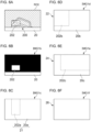
- Figs. 2A to 2D , 3A to 3F , and 4A and 4B are illustrations for describing an operation of the light distribution controlling device 6 according to Embodiment 1.
- the image processing unit 8 acquires an image IMG1 that is based on the first imaging device 4.
- the image IMG1 captures, at its left corner, roughly the right half of a front vehicle 200 and one luminous point 202 derived from a right lamp of the front vehicle 200.
- a lamp of a front vehicle 200 is, for example, a rear lamp if the front vehicle 200 is a leading vehicle or is, for example, a headlamp if the front vehicle 200 is an oncoming vehicle.
- a rear lamp includes a stop lamp and a tail lamp.
- Fig. 2A shows an image IMG1 captured when a light distribution pattern PTN is not formed, an image IMG1 is not limited to this image IMG1.
- the image processing unit 8 Upon acquiring the image IMG1, the image processing unit 8 generates a processed image IMG1a from the image IMG1, as shown in Fig. 2B .
- the processed image IMG1a is an image resulting from adding pixel lines 20 having a luminance value (pixel value) higher than a predetermined threshold to the ends of the image IMG1 in the width direction of the vehicle.
- the processed image IMG1a is edged with the pixel lines 20 at its right and left sides.
- Each of the pixel lines 20 is constituted, for example, by a line of pixels extending from the upper end to the lower end of the image IMG1.
- the width of a pixel line 20 is not limited to a single pixel.
- the threshold can be set in advance based on an experiment or simulation conducted by an engineer.
- the image processing unit 8 sends information about the processed image IMG1a to the region setting unit 10.
- the region setting unit 10 sets a processing region ROI in the processed image IMG1a, as shown in Fig. 2C .
- the processing region ROI includes the range in which the front vehicle 200 is present.
- the region setting unit 10 acquires information about the processing region ROI from the outside.
- the information about the processing region ROI may include, for example, the position coordinates of the processing region ROI in the image IMG1 or the angle of the processing region ROI relative to the host vehicle.
- the region setting unit 10 acquires the information about the processing region ROI from the vehicle ECU 16 provided in the vehicle.
- the vehicle ECU 16 generates the information about the processing region ROI, for example, as part of the control in the advanced driver-assistance system (ADAS). For example, as shown in Fig. 2D , the vehicle ECU 16 acquires a wide-angle image IMG2 that is based on a second imaging device 18. The second imaging device 18 has an imaging range broader than the light illumination range of the light distribution variable lamp 2. The vehicle ECU 16 then detects the front vehicle 200 from the wide-angle image IMG2 and generates position information of the front vehicle 200. The vehicle ECU 16 can detect the front vehicle 200 from the wide-angle image IMG2 with the use of a known technique, including algorithm recognition or deep learning.
- a known technique including algorithm recognition or deep learning.
- the vehicle ECU 16 can determine that the luminous point 202 in the wide-angle image IMG2 has been derived from a lamp of the front vehicle 200, or in other words, can detect the front vehicle 200, based, for example, on the position or pairedness of the luminous point 202. Pairedness of a luminous point means that a plurality of luminous points show the same behaviors while maintaining their distance.
- the imaging range of the second imaging device 18 is broader than the light illumination range of the light distribution variable lamp 2 and than the imaging range of the first imaging device 4. This configuration provides a high likelihood that, even when the first imaging device 4 can capture only a part of the front vehicle 200, the second imaging device 18 can capture the entire front vehicle 200. Hence, the vehicle ECU 16 can detect the front vehicle 200 from the wide-angle image IMG2.
- the vehicle ECU 16 sets the processing region ROI based on the position information of the front vehicle 200 and sends information about the processing region ROI to the region setting unit 10.
- the processing region ROI is a region that includes the entire front vehicle 200 and a predetermined range surrounding the front vehicle 200.
- the region setting unit 10 may detect the front vehicle 200 from the wide-angle image IMG2 and generate information about the processing region ROI.
- the region setting unit 10 sends the processed image IMG1a having the processing region ROI set therein to the image processing unit 8.
- the image processing unit 8 extracts the processing region ROI from the processed image IMG1a, as shown in Fig. 3A .
- the processed image IMG1a has been derived from the image IMG1 having an imaging range narrower than the imaging range of the wide-angle image IMG2. Therefore, the processing region ROI extracted from the processed image IMG1a includes only a part of the front vehicle 200. Hence, this processing region ROI includes only one luminous point 202 derived from the right lamp.
- the processing region ROI also includes the left pixel line 20.
- the image processing unit 8 performs an extracting process of extracting a high-luminance pixel from the processing region ROI with the use of a threshold that is based on the luminance value of the pixel line 20.
- This extracting process includes known image processing, such as binarization.
- This process generates an extracted image IMG1b in which the luminous point 202 derived from the lamp of the front vehicle 200 and the pixel line 20 have been extracted, as shown in Fig. 3B .
- the image processing unit 8 sends the generated extracted image IMG1b to the pattern determining unit 12.
- the pattern determining unit 12 sets a shaded portion 28 to overlap the front vehicle 200, based on high-luminance pixels included in the extracted image IMG1b. According to the present embodiment, the pattern determining unit 12 sets the shaded portion 28 based on a pair of high-luminance pixels arrayed in the width direction of the vehicle in the extracted image IMG1b. In one example, the pattern determining unit 12 performs a dilation process on the extracted image IMG1b to dilate high-luminance pixels in the upward direction and thus generates an upwardly dilated image IMG1c that includes an upwardly dilated group 21.
- the pattern determining unit 12 performs an upward dilation process on the extracted image IMG1b with the upper end pixel of the structuring element mapped to a pixel of interest.
- the dilation process when any of the pixels that the structuring element overlaps is a pixel of a high luminance value, the luminance value of the pixel of interest is changed to this high luminance value.
- the luminance value of the pixels located above a high-luminance pixel in the extracted image IMG1b is changed to the luminance value of the high-luminance pixel.
- the upwardly dilated image IMG1c that includes the upwardly dilated group 21, as shown in Fig. 3C , is generated.
- the upwardly dilated group 21 includes a first upwardly dilated group 202a formed as the luminous point 202 is dilated in the upward direction, and a second upwardly dilated group 20a formed as the pixel line 20 is dilated in the upward direction.
- the pixel line 20 extends from the upper end to the lower end in the extracted image IMG1b, the pixel line 20 and the second upwardly dilated group 20a have an identical shape.
- the pattern determining unit 12 then performs a dilation process on the upwardly dilated image IMG1c to dilate the upwardly dilated group 21 in the left direction and thus generates a leftwardly dilated image IMG1d that includes a leftwardly dilated group 22.
- the pattern determining unit 12 performs a leftward dilation process on the upwardly dilated image IMG1c with the left end pixel of the structuring element mapped to a pixel of interest.
- the luminance value of the pixels located to the left of a high-luminance pixel in the upwardly dilated image IMG1c is changed to the luminance value of the high-luminance pixel.
- the leftwardly dilated image IMG1d that includes the leftwardly dilated group 22, as shown in Fig. 3D is generated.
- the leftwardly dilated group 22 has a shape in which a first leftwardly dilated group 202b formed as the first upwardly dilated group 202a is dilated in the left direction and a second leftwardly dilated group 20b formed as the second upwardly dilated group 20a is dilated in the left direction are joined together.
- the second upwardly dilated group 20a is located at the left end of the upwardly dilated image IMG1c, the second upwardly dilated group 20a and the second leftwardly dilated group 20b have an identical shape.
- the pattern determining unit 12 also performs a dilation process on the upwardly dilated image IMG1c to dilate the upwardly dilated group 21 in the right direction and thus generates a rightwardly dilated image IMG1e that includes a rightwardly dilated group 24. Specifically, with the use of a structuring element having a predetermined shape elongated in the right-left direction, the pattern determining unit 12 performs a rightward dilation process on the upwardly dilated image IMG1c with the right end pixel of the structuring element mapped to a pixel of interest.
- the luminance value of the pixels located to the right of a high-luminance pixel in the upwardly dilated image IMG1c is changed to the luminance value of the high-luminance pixel.
- the rightwardly dilated image IMG1e that includes the rightwardly dilated group 24, as shown in Fig. 3E is generated.
- the rightwardly dilated group 24 has a shape in which a first rightwardly dilated group 202c formed as the first upwardly dilated group 202a is dilated in the right direction and a second rightwardly dilated group 20c formed as the second upwardly dilated group 20a is dilated in the right direction are joined together.
- the order of the rightward dilation process and the leftward dilation process is not set, and these processes can be performed in parallel.
- the pattern determining unit 12 then combines the leftwardly dilated image IMG1d and the rightwardly dilated image IMG1e. In other words, the pattern determining unit 12 performs an AND operation on the leftwardly dilated image IMG1d and the rightwardly dilated image IMG1e. This operation generates a combined image IMG1f that includes a combined pixel group 26, as shown in Fig. 3F .
- the combined pixel group 26 corresponds to a pixel region where the leftwardly dilated group 22 and the rightwardly dilated group 24 overlap.
- the pattern determining unit 12 sets the shaded portion 28 based on this combined pixel group 26. For example, the pattern determining unit 12 inverts the luminance value of each of the pixels in the combined image IMG1f and thus generates an inverted image IMG3 shown in Fig. 4A . In the inverted image IMG3, the combined pixel group 26 has a low luminance value, and the region other than the combined pixel group 26 has a high luminance value.
- the pattern determining unit 12 embeds the inverted image IMG3 into the region corresponding to the processing region ROI in the light distribution pattern serving as the base.
- the pattern determining unit 12 sets, as the shaded portion 28, the combined pixel group 26 itself in the light distribution pattern that serves as the base.
- the light distribution pattern PTN that includes the shaded portion 28 to overlap the front vehicle 200 is determined, as shown in Fig. 4B .
- the pattern determining unit 12 sends information about the determined light distribution pattern PTN to the lamp controlling unit 14.
- the shaded portion 28 is a portion of the light distribution pattern PTN of which the luminance (illuminance) is zero or a portion of the light distribution pattern PTN of which the luminance (illuminance) has been reduced to lower than the illuminance held before the shading but higher than zero.
- a light distribution pattern to serve as the base is selected in accordance with the light distribution mode that is determined based, for example, on the driver's instruction input by operating the light switch (not shown), the traveling state of the host vehicle, or the environment surrounding the host vehicle.
- the light distribution mode include, for example, a high beam mode of forming a high beam light distribution pattern and a low beam mode of forming a low beam light distribution pattern.
- Fig. 4B shows a high beam light distribution pattern.
- the lamp controlling unit 14 instructs the light distribution variable lamp 2 to form the light distribution pattern PTN.
- the lamp controlling unit 14 is constituted, for example, by a known LED driver module (LDM). If the light sources of the light distribution variable lamp 2 are controlled through analog dimming, the lamp controlling unit 14 adjusts the direct current level of the driving current flowing in the light sources. Meanwhile, if the light sources are controlled through pulse width modulation (PWM) dimming, the lamp control unit 14 adjusts the mean level of the driving current by switching the current that flows in the light sources and adjusting the ratio of the on periods. If the light distribution variable lamp 2 includes a DMD, the lamp controlling unit 14 may control the on/off switching of each of the mirror elements constituting the DMD. If the light distribution variable lamp 2 includes a liquid-crystal device, the lamp control unit 14 may control the optical transmittance of the liquid-crystal device. Thus, the light distribution pattern PTN is formed ahead of the host vehicle.
- LDM LED driver module
- the light distribution controlling device 6 generates a processed image IMG1a by adding pixel lines 20 of a high luminance to the ends, in the width direction of the vehicle, of an image IMG1 that is based on the first imaging device 4; extracts a processing region ROI from the processed image IMG1a; generates an extracted image IMG1b by subjecting the processing region ROI to an extracting process of extracting a high-luminance pixel; and sets a shaded portion 28 based on high-luminance pixels in the extracted image IMG1b.
- a shaded portion 28 is set based only on a luminous point 202 derived from the other lamp. This case does not allow for the formation of a valid shaded portion 28 that extends over the pair of lamps and can cause glare on the driver of the front vehicle 200. Broadening the imaging range of the first imaging device 4 can reduce the likelihood that one of the lamps of the front vehicle 200 goes outside the imaging range. This case, however, may necessitate a broader-angle first imaging device 4. Furthermore, the above case can lead to an increase in the processing load of the light distribution controlling device 6 or an increase in necessary memory.
- pixel lines 20 of a high luminance are added to the right and left ends of an image IMG1.
- the pixel lines 20 can be used as a substitute for a luminous point 202 derived from a lamp.
- the above configuration can guarantee that a luminous point 202 is present at the right or left end of an image IMG1. Therefore, even when one of the lamps of a front vehicle 200 goes off to the right or left of the imaging range of the first imaging device 4, a shaded portion 28 valid for this front vehicle 200 can be formed. Hence, reliability in forming a shaded portion can be increased.
- the imaging range of the first imaging device 4 matches the light illumination range of the light distribution variable lamp 2. Meanwhile, a processing region ROI is set based on a wide-angle image IMG2 broader than the light illumination range of the light distribution variable lamp 2.
- an upwardly dilated image IMG1c is generated from an extracted image IMG1b
- a leftwardly dilated image IMG1d and a rightwardly dilated image IMG1e are generated from the upwardly dilated image IMG1c
- the shaded portion 28 is set based on the leftwardly dilated image IMG1d and the rightwardly dilated image IMG1e.
- adding a pixel line 20 to an image IMG1 is particularly effective.
- the present embodiment has a configuration identical to the configuration of Embodiment 1 except for part of the content of light distribution control.
- the present embodiment will be described below with the description centered on its configuration that differs from the configuration of Embodiment 1, and the description of configuration that is common to both embodiments will be omitted, as appropriate.
- Figs. 5A to 5D , 6A to 6F , and 7A and 7B are illustrations for describing an operation of the light distribution controlling device 6 according to Embodiment 2.
- the image processing unit 8 acquires an image IMG1 that is based on the first imaging device 4.
- the image IMG1 captures, at its left corner, roughly the upper half of a front vehicle 200 that has tilted to the right and one luminous point 202 derived from a left lamp of the front vehicle 200.
- This kind of image IMG1 may be generated when the first imaging device 4 captures an image while the right-left axis of the host vehicle is tilted to a great extent, that is, while the host vehicle is tilted to a great extent in the roll direction.
- a straddle-type vehicle banks right and left to a great extent when traveling on a curved road, for example.
- Fig. 5A shows an image IMG1 captured when a light distribution pattern PTN is not formed, an image IMG1 is not limited to this image IMG1.
- the image processing unit 8 Upon acquiring the image IMG1, the image processing unit 8 generates a processed image IMG1a from the image IMG1, as shown in Fig. 5B .
- the image processing unit 8 according to the present embodiment generates the processed image IMG1a by adding pixel lines 20 to the ends of the image IMG1 in the width direction of the vehicle and also to the lower end of the image IMG1. Therefore, the processed image IMG1a is edged with the pixel lines 20 at its right, left, and lower sides.
- the image processing unit 8 sends information about the processed image IMG1a to the region setting unit 10.
- the region setting unit 10 sets a processing region ROI in the processed image IMG1a, as shown in Fig. 5C .
- the region setting unit 10 acquires information about the processing region ROI, for example, from the vehicle ECU 16.
- the vehicle ECU 16 detects the front vehicle 200 from a wide-angle image IMG2 broader than the light illumination range of the light distribution variable lamp 2, as shown in Fig. 5D .
- the vehicle ECU 16 sets the processing region ROI based on the position information of the front vehicle 200 and sends information about the processing region ROI to the region setting unit 10.
- the region setting unit 10 sends the processed image IMG1a having the processing region ROI set therein to the image processing unit 8.
- the image processing unit 8 extracts the processing region ROI from the processed image IMG1a, as shown in Fig. 6A .
- the processing region ROI includes the one luminous point 202 derived from the left lamp and the pixel line 20 at the lower side.
- the image processing unit 8 performs an extracting process of extracting a high-luminance pixel from the processing region ROI with the use of a threshold that is based on the luminance value of the pixel line 20. This process generates an extracted image IMG1b in which the luminous point 202 derived from the lamp of the front vehicle 200 and the pixel line 20 have been extracted, as shown in Fig. 6B .
- the image processing unit 8 sends the generated extracted image IMG1b to the pattern determining unit 12.
- the pattern determining unit 12 sets a shaded portion 28 to overlap the front vehicle 200, based on high-luminance pixels included in the extracted image IMG1b. According to the present embodiment, the pattern determining unit 12 sets the shaded portion 28 based on a pair of high-luminance pixels arrayed in the up-down direction in the extracted image IMG1b. In one example, the pattern determining unit 12 performs a dilation process on the extracted image IMG1b to dilate high-luminance pixels in the upward direction and thus generates an upwardly dilated image IMG1c that includes an upwardly dilated group 21, as shown in Fig. 6C .
- the upwardly dilated group 21 includes a first upwardly dilated group 202a formed as the luminous point 202 is dilated in the upward direction, and a second upwardly dilated group 20a formed as the pixel line 20 is dilated in the upward direction.
- the pixel line 20 extends between the left end and the right end of the extracted image IMG1b at its lower end. Therefore, the upwardly dilated image IMG1c is entirely covered with the second upwardly dilated group 20a.
- the pattern determining unit 12 then performs a dilation process on the upwardly dilated image IMG1c to dilate the upwardly dilated group 21 in the left direction and thus generates a leftwardly dilated image IMG1d that includes a leftwardly dilated group 22, as shown in Fig. 6D .
- the leftwardly dilated group 22 has a shape in which a first leftwardly dilated group 202b formed as the first upwardly dilated group 202a is dilated in the left direction and a second leftwardly dilated group 20b formed as the second upwardly dilated group 20a is dilated in the left direction are joined together.
- the upwardly dilated image IMG1c is entirely covered with the second upwardly dilated group 20a, the leftwardly dilated image IMG1d and the upwardly dilated image IMG1c are identical.
- the pattern determining unit 12 also performs a dilation process on the upwardly dilated image IMG1c to dilate the upwardly dilated group 21 in the right direction and thus generates a rightwardly dilated image IMG1e that includes a rightwardly dilated group 24, as shown in Fig. 6E .
- the rightwardly dilated group 24 has a shape in which a first rightwardly dilated group 202c formed as the first upwardly dilated group 202a is dilated in the right direction and a second rightwardly dilated group 20c formed as the second upwardly dilated group 20a is dilated in the right direction are joined together.
- the rightwardly dilated image IMG1e and the upwardly dilated image IMG1c are identical.
- the order of the rightward dilation process and the leftward dilation process is not set, and these processes can be performed in parallel.
- the pattern determining unit 12 then combines the leftwardly dilated image IMG1d and the rightwardly dilated image IMG1e. This operation generates a combined image IMG1f that includes a combined pixel group 26, as shown in Fig. 6F .
- the combined pixel group 26 corresponds to a pixel region where the leftwardly dilated group 22 and the rightwardly dilated group 24 overlap.
- the pattern determining unit 12 sets the shaded portion 28 based on this combined pixel group 26. For example, the pattern determining unit 12 inverts the luminance value of each of the pixels in the combined image IMG1f and thus generates an inverted image IMG3 shown in Fig. 7A . The pattern determining unit 12 then embeds the inverted image IMG3 into the light distribution pattern serving as the base and sets the combined pixel group 26 itself as the shaded portion 28. Thus, the light distribution pattern PTN that includes the shaded portion 28 to overlap the front vehicle 200 is determined, as shown in Fig. 7B . The pattern determining unit 12 sends information about the determined light distribution pattern PTN to the lamp controlling unit 14.
- the light distribution controlling device 6 generates a processed image IMG1a by adding pixel lines 20 to the ends, in the width direction of the vehicle, of an image IMG1 and to the lower end of the image IMG1; extracts a processing region ROI from the processed image IMG1a; generates an extracted image IMG1b from the processing region ROI; and sets a shaded portion 28 based on high-luminance pixels in the extracted image IMG1b.
- a light distribution controlling device (6) configured to:
- the light distribution controlling device (6) according to First Item, wherein the light distribution controlling device (6) adds the pixel line (20) also to a lower end of the image (IMG1).
- the light distribution controlling device (6) according to any one of First Item to Third Item, wherein the light distribution controlling device (6)
- the light distribution controlling device (6) according to Second Item, wherein the first imaging device (4) is provided in a straddle-type vehicle.
- a vehicle lamp system (1) comprising:
- a light distribution controlling method comprising:
- the present invention can be used in light distribution controlling devices, vehicle lamp systems, and light distribution controlling methods.
- 1 vehicle lamp system 2 light distribution variable lamp, 4 first imaging device, 6 light distribution controlling device, 20 pixel line, 21 upwardly dilated group, 22 leftwardly dilated group, 24 rightwardly dilated group, 28 shaded portion, IMG1 image, IMG1a processed image, IMG1b extracted image, IMG1c upwardly dilated image, IMG1d leftwardly dilated image, IMG1e rightwardly dilated image, ROI processing region
Landscapes
- Engineering & Computer Science (AREA)
- Mechanical Engineering (AREA)
- General Engineering & Computer Science (AREA)
- Lighting Device Outwards From Vehicle And Optical Signal (AREA)
Abstract
Description
- The present invention relates to light distribution controlling devices, vehicle lamp systems, and light distribution controlling methods.
- Adaptive driving beam (ADB) control is being proposed that dynamically and adaptively controls light distribution patterns based on the circumstances surrounding the vehicle. ADB control detects, with a camera, the presence of a front vehicle that should not be illuminated with high-luminance light and blocks the region of the light that corresponds to the front vehicle (see, for example, Patent Literature 1). Blocking the region of the light that corresponds to the front vehicle can reduce glare caused on the driver of the front vehicle and can also improve the visibility for the driver of the host vehicle.
- Patent Literature 1:
JP 2015-064964 - When ADB control is implemented, it is desired that there be no failure to form a shaded portion.
- The present invention has been made in view of such circumstances and is directed, in one aspect, to providing a technology that increases reliability in forming a shaded portion.
- To address the problem above, one aspect of the present invention provides a light distribution controlling device. This light distribution controlling device is configured to generate a processed image by adding a pixel line of a luminance value higher than a predetermined threshold to an end, in a width direction of a vehicle, of an image that is based on a first imaging device that captures an image of a region ahead of the vehicle; extract, from the processed image, a processing region that includes a front vehicle; generate an extracted image by subjecting the processing region to an extracting process of extracting a high-luminance pixel with use of the threshold; and set a shaded portion to overlap the front vehicle based on a pair of high-luminance pixels included in the extracted image and determine a light distribution pattern that includes the shaded portion.
- Another aspect of the present invention provides a vehicle lamp system. This vehicle lamp system includes a light distribution variable lamp capable of forming a light distribution pattern that includes a shaded portion to overlap a front vehicle, a first imaging device that captures an image of a region ahead of a vehicle, and the light distribution controlling device according to the aspect above that controls formation of the light distribution pattern by the light distribution variable lamp.
- Another aspect of the present invention provides a light distribution controlling method. This light distribution controlling method includes generating a processed image by adding a pixel line of a luminance value higher than a predetermined threshold to an end, in a width direction of a vehicle, of an image that is based on a first imaging device that captures an image of a region ahead of the vehicle; extracting, from the processed image, a processing region that includes a front vehicle; generating an extracted image by subjecting the processing region to an extracting process of extracting a high-luminance pixel with use of the threshold; and setting a shaded portion to overlap the front vehicle based on a pair of high-luminance pixels included in the extracted image and determining a light distribution pattern that includes the shaded portion.
- It is to be noted that any combinations of the constituent elements above or an embodiment obtained by converting what is expressed by the present invention between a method, an apparatus, a system, and so forth is also valid as an aspect of the present invention.
- The present invention can increase reliability in forming a shaded portion.
-
- [
Fig. 1] Fig. 1 is a block diagram of a vehicle lamp system. - [
Fig. 2] Figs. 2A to 2D are illustrations for describing an operation of a light distribution controlling device according toEmbodiment 1. - [
Fig. 3] Figs. 3A to 3F are illustrations for describing an operation of a light distribution controlling device according toEmbodiment 1. - [
Fig. 4] Figs. 4A and 4B are illustrations for describing an operation of a light distribution controlling device according toEmbodiment 1. - [
Fig. 5] Figs. 5A to 5D are illustrations for describing an operation of a light distribution controlling device according toEmbodiment 2. - [
Fig. 6] Figs. 6A to 6F are illustrations for describing an operation of a light distribution controlling device according toEmbodiment 2. - [
Fig. 7] Figs. 7A and 7B are illustrations for describing an operation of a light distribution controlling device according toEmbodiment 2. - Hereinafter, the present invention will be described based on some exemplary embodiments and with reference to the drawings. The embodiments are illustrative in nature and are not intended to limit the invention. Not all the features and combinations thereof described in the embodiments are necessarily essential to the invention. Identical or equivalent constituent elements, members, and processes shown in the drawings are given identical reference characters, and their duplicate description will be omitted, as appropriate. The scales and shapes of the components shown in the drawings are set merely for convenience in order to facilitate the description and are not to be interpreted as limiting, unless specifically indicated otherwise. When terms such as "first" and "second" are used in the present specification or in the claims, these terms do not indicate the order or the level of importance in any way and are merely used to distinguish a given component from another component, unless specifically indicated otherwise. Members that are not important in describing the embodiments are partly omitted from the drawings.
-
Fig. 1 is a block diagram of avehicle lamp system 1.Fig. 1 depicts constituent elements of thevehicle lamp system 1 in the form of functional blocks. These functional blocks are implemented, in terms of their hardware configuration, by elements and/or circuits, such as a CPU and a memory of a computer, or implemented, in terms of their software configuration, by a computer program or the like. It is to be appreciated by a person skilled in the art that these functional blocks can be implemented in a variety of forms through combinations of hardware and software. - The
vehicle lamp system 1 includes a lightdistribution variable lamp 2, afirst imaging device 4, and a light distribution controllingdevice 6. These components are provided in a vehicle. According to the present embodiment, the vehicle in which thevehicle lamp system 1 is provided is a straddle-type vehicle, such as a motorcycle. The lightdistribution variable lamp 2, thefirst imaging device 4, and the light distribution controllingdevice 6 may all be contained within a single housing, or some of these members may be provided outside such a housing. For example, the lightdistribution variable lamp 2, thefirst imaging device 4, and the light distribution controllingdevice 6 are housed in a lamp room. The lamp room is defined by a lamp body having an opening that opens to the front of the vehicle and a light-transmissive cover attached so as to cover the opening of the lamp body. Thefirst imaging device 4 and the light distribution controllingdevice 6 may be provided outside the lamp room. In this case, thefirst imaging device 4 may be an onboard camera. The light distribution controllingdevice 6 may be, for example, entirely or partly embedded in avehicle ECU 16. - The light
distribution variable lamp 2 is capable of forming a light distribution pattern PTN that includes a shaded portion to overlap a front vehicle. For example, the lightdistribution variable lamp 2 illuminates a region ahead of the host vehicle with a visible light beam L1 of a variable intensity distribution. The lightdistribution variable lamp 2 is enabled to vary, independently of each other, the illuminance of light illuminating a plurality of individual regions R arrayed ahead. The plurality of individual regions R are arrayed, for example, in a matrix. The lightdistribution variable lamp 2 receives information instructing on a light distribution pattern PTN from the light distribution controllingdevice 6 and emits a visible light beam L1 having an intensity distribution corresponding to the light distribution pattern PTN. Thus, the light distribution pattern PTN is formed ahead of the host vehicle. A light distribution pattern PTN is understood as a two- dimensional illuminance distribution of anillumination pattern 902 that the lightdistribution variable lamp 2 forms on an imaginaryvertical screen 900 ahead of the host vehicle. - There is no particular limitation on the configuration of the light
distribution variable lamp 2, and the lightdistribution variable lamp 2 includes, for example, a plurality of light sources arrayed in a matrix and a lighting circuit that drives the light sources to turn them on independently of each other. Although there is no particular limitation on the light sources, some preferred examples of such a light source include a semiconductor light source, such as a light-emitting diode (LED), a laser diode (LD), and an organic or inorganic electroluminescence (EL) light source. The light sources are mapped to the respective individual regions R, and each individual region R is individually illuminated with light from the corresponding light source. The lightdistribution variable lamp 2 has a resolution, that is, a light distribution resolving power of, for example, from 1,000 pixels to 2,000,000 pixels. The resolution of the lightdistribution variable lamp 2 means the number of the unit regions, of a light distribution pattern PTN, whose illuminance can be varied independently of each other. - In order to form an illuminance distribution corresponding to a light distribution pattern PTN, the light
distribution variable lamp 2 may include, for example but not limited to, a pattern forming device of a matrix type, such as a digital mirror device (DMD) or a liquid-crystal device, or a pattern forming device of a scan optics type that scans the region ahead of the host vehicle with light from the light sources. - The
first imaging device 4 has a sensitivity to a visible light range and repeatedly captures an image of the region ahead of the host vehicle. Thefirst imaging device 4 captures an image of reflected light of a visible light beam L1 reflected by an object ahead of the vehicle. Thefirst imaging device 4 also captures an image of light from a front vehicle, which includes a leading vehicle and an oncoming vehicle. An image IMG1 that thefirst imaging device 4 generates is sent to the lightdistribution controlling device 6. The imaging range of thefirst imaging device 4 matches the light illumination range of the lightdistribution variable lamp 2. Therefore, the outer edge of an image IMG1 and the outer edge of the range in which a light distribution pattern PTN can be formed overlap each other. - An image IMG1 that the light
distribution controlling device 6 acquires from thefirst imaging device 4 may be RAW image data or image data subjected to predetermined image processing by thefirst imaging device 4. When the lightdistribution controlling device 6 receives image data resulting from subjecting RAW image data generated by thefirst imaging device 4 to image processing performed by a processing device other than thefirst imaging device 4, this receiving also corresponds to the acquiring of an image IMG1 from thefirst imaging device 4. In the following description, "an image IMG1 that is based on afirst imaging device 4" may mean either of RAW image data and data subjected to image processing. Furthermore, the term "image IMG1" may be used without any distinction between the two types of image data. - The light
distribution controlling device 6 executes ADB control of dynamically and adaptively controlling the light distribution of the lightdistribution variable lamp 2 in accordance with a target present in the region ahead. The lightdistribution controlling device 6 determines a light distribution pattern PTN that includes a shaded portion to overlap a front vehicle, with the use of an image IMG1 that is based on thefirst imaging device 4. The lightdistribution controlling device 6 then sends information instructing on the determined light distribution pattern PTN to the lightdistribution variable lamp 2. The lightdistribution controlling device 6 can be constituted by a digital processor and may, for example, be constituted by a combination of a microcomputer including a CPU and a software program or by a field-programmable gate array (FPGA), an application specific IC (ASIC), or the like. The lightdistribution controlling device 6 includes, in one example, animage processing unit 8, aregion setting unit 10, apattern determining unit 12, and alamp controlling unit 14. Each of these units operates as the integrated circuit constituting itself executes a program stored in a memory. -
Figs. 2A to 2D ,3A to 3F , and4A and 4B are illustrations for describing an operation of the lightdistribution controlling device 6 according toEmbodiment 1. First, as shown inFig. 2A , theimage processing unit 8 acquires an image IMG1 that is based on thefirst imaging device 4. In one example, the image IMG1 captures, at its left corner, roughly the right half of afront vehicle 200 and oneluminous point 202 derived from a right lamp of thefront vehicle 200. A lamp of afront vehicle 200 is, for example, a rear lamp if thefront vehicle 200 is a leading vehicle or is, for example, a headlamp if thefront vehicle 200 is an oncoming vehicle. A rear lamp includes a stop lamp and a tail lamp. AlthoughFig. 2A shows an image IMG1 captured when a light distribution pattern PTN is not formed, an image IMG1 is not limited to this image IMG1. - Upon acquiring the image IMG1, the
image processing unit 8 generates a processed image IMG1a from the image IMG1, as shown inFig. 2B . The processed image IMG1a is an image resulting from addingpixel lines 20 having a luminance value (pixel value) higher than a predetermined threshold to the ends of the image IMG1 in the width direction of the vehicle. In other words, the processed image IMG1a is edged with the pixel lines 20 at its right and left sides. Each of the pixel lines 20 is constituted, for example, by a line of pixels extending from the upper end to the lower end of the image IMG1. Herein, the width of apixel line 20 is not limited to a single pixel. The threshold can be set in advance based on an experiment or simulation conducted by an engineer. Theimage processing unit 8 sends information about the processed image IMG1a to theregion setting unit 10. - The
region setting unit 10 sets a processing region ROI in the processed image IMG1a, as shown inFig. 2C . The processing region ROI includes the range in which thefront vehicle 200 is present. Theregion setting unit 10 according to the present embodiment acquires information about the processing region ROI from the outside. The information about the processing region ROI may include, for example, the position coordinates of the processing region ROI in the image IMG1 or the angle of the processing region ROI relative to the host vehicle. In one example, theregion setting unit 10 acquires the information about the processing region ROI from thevehicle ECU 16 provided in the vehicle. - The
vehicle ECU 16 generates the information about the processing region ROI, for example, as part of the control in the advanced driver-assistance system (ADAS). For example, as shown inFig. 2D , thevehicle ECU 16 acquires a wide-angle image IMG2 that is based on asecond imaging device 18. Thesecond imaging device 18 has an imaging range broader than the light illumination range of the lightdistribution variable lamp 2. Thevehicle ECU 16 then detects thefront vehicle 200 from the wide-angle image IMG2 and generates position information of thefront vehicle 200. Thevehicle ECU 16 can detect thefront vehicle 200 from the wide-angle image IMG2 with the use of a known technique, including algorithm recognition or deep learning. - The
vehicle ECU 16 can determine that theluminous point 202 in the wide-angle image IMG2 has been derived from a lamp of thefront vehicle 200, or in other words, can detect thefront vehicle 200, based, for example, on the position or pairedness of theluminous point 202. Pairedness of a luminous point means that a plurality of luminous points show the same behaviors while maintaining their distance. The imaging range of thesecond imaging device 18 is broader than the light illumination range of the lightdistribution variable lamp 2 and than the imaging range of thefirst imaging device 4. This configuration provides a high likelihood that, even when thefirst imaging device 4 can capture only a part of thefront vehicle 200, thesecond imaging device 18 can capture the entirefront vehicle 200. Hence, thevehicle ECU 16 can detect thefront vehicle 200 from the wide-angle image IMG2. - The
vehicle ECU 16 then sets the processing region ROI based on the position information of thefront vehicle 200 and sends information about the processing region ROI to theregion setting unit 10. In one example, the processing region ROI is a region that includes the entirefront vehicle 200 and a predetermined range surrounding thefront vehicle 200. Herein, theregion setting unit 10 may detect thefront vehicle 200 from the wide-angle image IMG2 and generate information about the processing region ROI. - The
region setting unit 10 sends the processed image IMG1a having the processing region ROI set therein to theimage processing unit 8. Theimage processing unit 8 extracts the processing region ROI from the processed image IMG1a, as shown inFig. 3A . The processed image IMG1a has been derived from the image IMG1 having an imaging range narrower than the imaging range of the wide-angle image IMG2. Therefore, the processing region ROI extracted from the processed image IMG1a includes only a part of thefront vehicle 200. Hence, this processing region ROI includes only oneluminous point 202 derived from the right lamp. The processing region ROI also includes theleft pixel line 20. - The
image processing unit 8 performs an extracting process of extracting a high-luminance pixel from the processing region ROI with the use of a threshold that is based on the luminance value of thepixel line 20. This extracting process includes known image processing, such as binarization. This process generates an extracted image IMG1b in which theluminous point 202 derived from the lamp of thefront vehicle 200 and thepixel line 20 have been extracted, as shown inFig. 3B . Theimage processing unit 8 sends the generated extracted image IMG1b to thepattern determining unit 12. - The
pattern determining unit 12 sets a shadedportion 28 to overlap thefront vehicle 200, based on high-luminance pixels included in the extracted image IMG1b. According to the present embodiment, thepattern determining unit 12 sets the shadedportion 28 based on a pair of high-luminance pixels arrayed in the width direction of the vehicle in the extracted image IMG1b. In one example, thepattern determining unit 12 performs a dilation process on the extracted image IMG1b to dilate high-luminance pixels in the upward direction and thus generates an upwardly dilated image IMG1c that includes an upwardly dilatedgroup 21. - Specifically, with the use of a structuring element having a predetermined shape elongated in the up-down direction, the
pattern determining unit 12 performs an upward dilation process on the extracted image IMG1b with the upper end pixel of the structuring element mapped to a pixel of interest. In the dilation process, when any of the pixels that the structuring element overlaps is a pixel of a high luminance value, the luminance value of the pixel of interest is changed to this high luminance value. Hence, in the upward dilation process, the luminance value of the pixels located above a high-luminance pixel in the extracted image IMG1b is changed to the luminance value of the high-luminance pixel. As a result, the upwardly dilated image IMG1c that includes the upwardly dilatedgroup 21, as shown inFig. 3C , is generated. The upwardly dilatedgroup 21 includes a first upwardly dilatedgroup 202a formed as theluminous point 202 is dilated in the upward direction, and a second upwardly dilatedgroup 20a formed as thepixel line 20 is dilated in the upward direction. Herein, since thepixel line 20 extends from the upper end to the lower end in the extracted image IMG1b, thepixel line 20 and the second upwardly dilatedgroup 20a have an identical shape. - The
pattern determining unit 12 then performs a dilation process on the upwardly dilated image IMG1c to dilate the upwardly dilatedgroup 21 in the left direction and thus generates a leftwardly dilated image IMG1d that includes a leftwardly dilatedgroup 22. Specifically, with the use of a structuring element having a predetermined shape elongated in the right-left direction, thepattern determining unit 12 performs a leftward dilation process on the upwardly dilated image IMG1c with the left end pixel of the structuring element mapped to a pixel of interest. In the leftward dilation process, the luminance value of the pixels located to the left of a high-luminance pixel in the upwardly dilated image IMG1c is changed to the luminance value of the high-luminance pixel. As a result, the leftwardly dilated image IMG1d that includes the leftwardly dilatedgroup 22, as shown inFig. 3D , is generated. The leftwardly dilatedgroup 22 has a shape in which a first leftwardly dilatedgroup 202b formed as the first upwardly dilatedgroup 202a is dilated in the left direction and a second leftwardly dilatedgroup 20b formed as the second upwardly dilatedgroup 20a is dilated in the left direction are joined together. Herein, since the second upwardly dilatedgroup 20a is located at the left end of the upwardly dilated image IMG1c, the second upwardly dilatedgroup 20a and the second leftwardly dilatedgroup 20b have an identical shape. - The
pattern determining unit 12 also performs a dilation process on the upwardly dilated image IMG1c to dilate the upwardly dilatedgroup 21 in the right direction and thus generates a rightwardly dilated image IMG1e that includes a rightwardly dilatedgroup 24. Specifically, with the use of a structuring element having a predetermined shape elongated in the right-left direction, thepattern determining unit 12 performs a rightward dilation process on the upwardly dilated image IMG1c with the right end pixel of the structuring element mapped to a pixel of interest. In the rightward dilation process, the luminance value of the pixels located to the right of a high-luminance pixel in the upwardly dilated image IMG1c is changed to the luminance value of the high-luminance pixel. As a result, the rightwardly dilated image IMG1e that includes the rightwardly dilatedgroup 24, as shown inFig. 3E , is generated. The rightwardly dilatedgroup 24 has a shape in which a first rightwardly dilatedgroup 202c formed as the first upwardly dilatedgroup 202a is dilated in the right direction and a second rightwardly dilatedgroup 20c formed as the second upwardly dilatedgroup 20a is dilated in the right direction are joined together. Herein, the order of the rightward dilation process and the leftward dilation process is not set, and these processes can be performed in parallel. - The
pattern determining unit 12 then combines the leftwardly dilated image IMG1d and the rightwardly dilated image IMG1e. In other words, thepattern determining unit 12 performs an AND operation on the leftwardly dilated image IMG1d and the rightwardly dilated image IMG1e. This operation generates a combined image IMG1f that includes a combinedpixel group 26, as shown inFig. 3F . The combinedpixel group 26 corresponds to a pixel region where the leftwardly dilatedgroup 22 and the rightwardly dilatedgroup 24 overlap. - The
pattern determining unit 12 sets the shadedportion 28 based on this combinedpixel group 26. For example, thepattern determining unit 12 inverts the luminance value of each of the pixels in the combined image IMG1f and thus generates an inverted image IMG3 shown inFig. 4A . In the inverted image IMG3, the combinedpixel group 26 has a low luminance value, and the region other than the combinedpixel group 26 has a high luminance value. Thepattern determining unit 12 embeds the inverted image IMG3 into the region corresponding to the processing region ROI in the light distribution pattern serving as the base. Thepattern determining unit 12 then sets, as the shadedportion 28, the combinedpixel group 26 itself in the light distribution pattern that serves as the base. Thus, the light distribution pattern PTN that includes the shadedportion 28 to overlap thefront vehicle 200 is determined, as shown inFig. 4B . Thepattern determining unit 12 sends information about the determined light distribution pattern PTN to thelamp controlling unit 14. - The shaded
portion 28 is a portion of the light distribution pattern PTN of which the luminance (illuminance) is zero or a portion of the light distribution pattern PTN of which the luminance (illuminance) has been reduced to lower than the illuminance held before the shading but higher than zero. A light distribution pattern to serve as the base is selected in accordance with the light distribution mode that is determined based, for example, on the driver's instruction input by operating the light switch (not shown), the traveling state of the host vehicle, or the environment surrounding the host vehicle. The light distribution mode include, for example, a high beam mode of forming a high beam light distribution pattern and a low beam mode of forming a low beam light distribution pattern. As one example,Fig. 4B shows a high beam light distribution pattern. - The
lamp controlling unit 14 instructs the lightdistribution variable lamp 2 to form the light distribution pattern PTN. Thelamp controlling unit 14 is constituted, for example, by a known LED driver module (LDM). If the light sources of the lightdistribution variable lamp 2 are controlled through analog dimming, thelamp controlling unit 14 adjusts the direct current level of the driving current flowing in the light sources. Meanwhile, if the light sources are controlled through pulse width modulation (PWM) dimming, thelamp control unit 14 adjusts the mean level of the driving current by switching the current that flows in the light sources and adjusting the ratio of the on periods. If the lightdistribution variable lamp 2 includes a DMD, thelamp controlling unit 14 may control the on/off switching of each of the mirror elements constituting the DMD. If the lightdistribution variable lamp 2 includes a liquid-crystal device, thelamp control unit 14 may control the optical transmittance of the liquid-crystal device. Thus, the light distribution pattern PTN is formed ahead of the host vehicle. - As described above, the light
distribution controlling device 6 according to the present embodiment generates a processed image IMG1a by addingpixel lines 20 of a high luminance to the ends, in the width direction of the vehicle, of an image IMG1 that is based on thefirst imaging device 4; extracts a processing region ROI from the processed image IMG1a; generates an extracted image IMG1b by subjecting the processing region ROI to an extracting process of extracting a high-luminance pixel; and sets a shadedportion 28 based on high-luminance pixels in the extracted image IMG1b. - When a
front vehicle 200 is located at an end of the imaging range of thefirst imaging device 4 and one of the lamps is outside the imaging range of thefirst imaging device 4, a shadedportion 28 is set based only on aluminous point 202 derived from the other lamp. This case does not allow for the formation of a valid shadedportion 28 that extends over the pair of lamps and can cause glare on the driver of thefront vehicle 200. Broadening the imaging range of thefirst imaging device 4 can reduce the likelihood that one of the lamps of thefront vehicle 200 goes outside the imaging range. This case, however, may necessitate a broader-anglefirst imaging device 4. Furthermore, the above case can lead to an increase in the processing load of the lightdistribution controlling device 6 or an increase in necessary memory. - In contrast, according to the present embodiment,
pixel lines 20 of a high luminance are added to the right and left ends of an image IMG1. The pixel lines 20 can be used as a substitute for aluminous point 202 derived from a lamp. Thus, the above configuration can guarantee that aluminous point 202 is present at the right or left end of an image IMG1. Therefore, even when one of the lamps of afront vehicle 200 goes off to the right or left of the imaging range of thefirst imaging device 4, a shadedportion 28 valid for thisfront vehicle 200 can be formed. Hence, reliability in forming a shaded portion can be increased. - According to the present embodiment, the imaging range of the
first imaging device 4 matches the light illumination range of the lightdistribution variable lamp 2. Meanwhile, a processing region ROI is set based on a wide-angle image IMG2 broader than the light illumination range of the lightdistribution variable lamp 2. In the process of determining a shadedportion 28, an upwardly dilated image IMG1c is generated from an extracted image IMG1b, a leftwardly dilated image IMG1d and a rightwardly dilated image IMG1e are generated from the upwardly dilated image IMG1c, and the shadedportion 28 is set based on the leftwardly dilated image IMG1d and the rightwardly dilated image IMG1e. In this case, adding apixel line 20 to an image IMG1 is particularly effective. - The present embodiment has a configuration identical to the configuration of
Embodiment 1 except for part of the content of light distribution control. The present embodiment will be described below with the description centered on its configuration that differs from the configuration ofEmbodiment 1, and the description of configuration that is common to both embodiments will be omitted, as appropriate.Figs. 5A to 5D ,6A to 6F , and7A and 7B are illustrations for describing an operation of the lightdistribution controlling device 6 according toEmbodiment 2. - First, as shown in
Fig. 5A , theimage processing unit 8 acquires an image IMG1 that is based on thefirst imaging device 4. In one example, the image IMG1 captures, at its left corner, roughly the upper half of afront vehicle 200 that has tilted to the right and oneluminous point 202 derived from a left lamp of thefront vehicle 200. This kind of image IMG1 may be generated when thefirst imaging device 4 captures an image while the right-left axis of the host vehicle is tilted to a great extent, that is, while the host vehicle is tilted to a great extent in the roll direction. In particular, a straddle-type vehicle banks right and left to a great extent when traveling on a curved road, for example. Therefore, the kind of image IMG1 described above is more likely to be generated when thefirst imaging device 4 is provided in a straddle-type vehicle. AlthoughFig. 5A shows an image IMG1 captured when a light distribution pattern PTN is not formed, an image IMG1 is not limited to this image IMG1. - Upon acquiring the image IMG1, the
image processing unit 8 generates a processed image IMG1a from the image IMG1, as shown inFig. 5B . Theimage processing unit 8 according to the present embodiment generates the processed image IMG1a by addingpixel lines 20 to the ends of the image IMG1 in the width direction of the vehicle and also to the lower end of the image IMG1. Therefore, the processed image IMG1a is edged with the pixel lines 20 at its right, left, and lower sides. Theimage processing unit 8 sends information about the processed image IMG1a to theregion setting unit 10. - The
region setting unit 10 sets a processing region ROI in the processed image IMG1a, as shown inFig. 5C . Theregion setting unit 10 according to the present embodiment acquires information about the processing region ROI, for example, from thevehicle ECU 16. Thevehicle ECU 16 detects thefront vehicle 200 from a wide-angle image IMG2 broader than the light illumination range of the lightdistribution variable lamp 2, as shown inFig. 5D . Thevehicle ECU 16 then sets the processing region ROI based on the position information of thefront vehicle 200 and sends information about the processing region ROI to theregion setting unit 10. - The
region setting unit 10 sends the processed image IMG1a having the processing region ROI set therein to theimage processing unit 8. Theimage processing unit 8 extracts the processing region ROI from the processed image IMG1a, as shown inFig. 6A . The processing region ROI includes the oneluminous point 202 derived from the left lamp and thepixel line 20 at the lower side. Theimage processing unit 8 performs an extracting process of extracting a high-luminance pixel from the processing region ROI with the use of a threshold that is based on the luminance value of thepixel line 20. This process generates an extracted image IMG1b in which theluminous point 202 derived from the lamp of thefront vehicle 200 and thepixel line 20 have been extracted, as shown inFig. 6B . Theimage processing unit 8 sends the generated extracted image IMG1b to thepattern determining unit 12. - The
pattern determining unit 12 sets a shadedportion 28 to overlap thefront vehicle 200, based on high-luminance pixels included in the extracted image IMG1b. According to the present embodiment, thepattern determining unit 12 sets the shadedportion 28 based on a pair of high-luminance pixels arrayed in the up-down direction in the extracted image IMG1b. In one example, thepattern determining unit 12 performs a dilation process on the extracted image IMG1b to dilate high-luminance pixels in the upward direction and thus generates an upwardly dilated image IMG1c that includes an upwardly dilatedgroup 21, as shown inFig. 6C . The upwardly dilatedgroup 21 includes a first upwardly dilatedgroup 202a formed as theluminous point 202 is dilated in the upward direction, and a second upwardly dilatedgroup 20a formed as thepixel line 20 is dilated in the upward direction. Herein, thepixel line 20 extends between the left end and the right end of the extracted image IMG1b at its lower end. Therefore, the upwardly dilated image IMG1c is entirely covered with the second upwardly dilatedgroup 20a. - The
pattern determining unit 12 then performs a dilation process on the upwardly dilated image IMG1c to dilate the upwardly dilatedgroup 21 in the left direction and thus generates a leftwardly dilated image IMG1d that includes a leftwardly dilatedgroup 22, as shown inFig. 6D . The leftwardly dilatedgroup 22 has a shape in which a first leftwardly dilatedgroup 202b formed as the first upwardly dilatedgroup 202a is dilated in the left direction and a second leftwardly dilatedgroup 20b formed as the second upwardly dilatedgroup 20a is dilated in the left direction are joined together. Herein, since the upwardly dilated image IMG1c is entirely covered with the second upwardly dilatedgroup 20a, the leftwardly dilated image IMG1d and the upwardly dilated image IMG1c are identical. - The
pattern determining unit 12 also performs a dilation process on the upwardly dilated image IMG1c to dilate the upwardly dilatedgroup 21 in the right direction and thus generates a rightwardly dilated image IMG1e that includes a rightwardly dilatedgroup 24, as shown inFig. 6E . The rightwardly dilatedgroup 24 has a shape in which a first rightwardly dilatedgroup 202c formed as the first upwardly dilatedgroup 202a is dilated in the right direction and a second rightwardly dilatedgroup 20c formed as the second upwardly dilatedgroup 20a is dilated in the right direction are joined together. Herein, since the upwardly dilated image IMG1c is entirely covered with the second upwardly dilatedgroup 20a, the rightwardly dilated image IMG1e and the upwardly dilated image IMG1c are identical. The order of the rightward dilation process and the leftward dilation process is not set, and these processes can be performed in parallel. - The
pattern determining unit 12 then combines the leftwardly dilated image IMG1d and the rightwardly dilated image IMG1e. This operation generates a combined image IMG1f that includes a combinedpixel group 26, as shown inFig. 6F . The combinedpixel group 26 corresponds to a pixel region where the leftwardly dilatedgroup 22 and the rightwardly dilatedgroup 24 overlap. - The
pattern determining unit 12 sets the shadedportion 28 based on this combinedpixel group 26. For example, thepattern determining unit 12 inverts the luminance value of each of the pixels in the combined image IMG1f and thus generates an inverted image IMG3 shown inFig. 7A . Thepattern determining unit 12 then embeds the inverted image IMG3 into the light distribution pattern serving as the base and sets the combinedpixel group 26 itself as the shadedportion 28. Thus, the light distribution pattern PTN that includes the shadedportion 28 to overlap thefront vehicle 200 is determined, as shown inFig. 7B . Thepattern determining unit 12 sends information about the determined light distribution pattern PTN to thelamp controlling unit 14. - As described above, the light
distribution controlling device 6 according to the present embodiment generates a processed image IMG1a by addingpixel lines 20 to the ends, in the width direction of the vehicle, of an image IMG1 and to the lower end of the image IMG1; extracts a processing region ROI from the processed image IMG1a; generates an extracted image IMG1b from the processing region ROI; and sets a shadedportion 28 based on high-luminance pixels in the extracted image IMG1b. With this configuration, even when one of the lamps of afront vehicle 200 goes outside and below the imaging range of thefirst imaging device 4, a shadedportion 28 valid for thisfront vehicle 200 can be formed. Hence, reliability in forming a shaded portion can be increased. - Thus far, some embodiments according to the present invention have been described in detail. The embodiments described above merely illustrate some specific examples for implementing the present invention. The content of the embodiments does not limit the technical scope of the present invention, and a number of design changes, including modifications, additions, and deletions of constituent elements, can be made within the scope that does not depart from the sprit of the invention set forth in the claims. A new embodiment resulting from adding a design change has advantageous effects of the embodiments combined as well as the advantageous effects of the modification. With regard to the embodiments described above, the expressions "according to the present embodiment," "in the present embodiment," and so on are added for emphasis to the content that can be subjected to a design change as described above, but a design change is also permitted on the content without these expressions. A desired combination of the constituent elements described above is also valid as an aspect of the present invention. Hatching added along a section in the drawings does not limit the material of such with hatching.
- The invention according to the embodiments described above may be identified by the items indicated below.
- A light distribution controlling device (6) configured to:
- generate a processed image (IMG1a) by adding a pixel line (20) of a luminance value higher than a predetermined threshold to an end, in a width direction of a vehicle, of an image (IMG1) that is based on a first imaging device (4) that captures an image of a region ahead of the vehicle;
- extract, from the processed image (IMG1a), a processing region (ROI) that includes a front vehicle (200);
- generate an extracted image (IMG1b) by subjecting the processing region (ROI) to an extracting process of extracting a high-luminance pixel (20, 202) with use of the threshold; and
- set a shaded portion (28) to overlap the front vehicle (200) based on a pair of high-luminance pixels (20, 202) included in the extracted image (IMG1b) and determine a light distribution pattern (PTN) that includes the shaded portion (28) .
- The light distribution controlling device (6) according to First Item, wherein
the light distribution controlling device (6) adds the pixel line (20) also to a lower end of the image (IMG1). - The light distribution controlling device (6) according to First Item or Second Item, wherein
- the image (IMG1) is an image of an imaging range matching a light illumination range of a light distribution variable lamp (2) that forms the light distribution pattern (PTN), and
- the processing region (ROI) is set based on position information of the front vehicle (200) detected from a wide-angle image (IMG2) that is based on a second imaging device (18) having an imaging range broader than the light illumination range.
- The light distribution controlling device (6) according to any one of First Item to Third Item, wherein the light distribution controlling device (6)
- generates an upwardly dilated image (IMG1c) that includes an upwardly dilated group (21) by subjecting the extracted image (IMG1b) to a dilation process of dilating the high-luminance pixel (20, 202) in an upward direction,
- generates a leftwardly dilated image (IMG1d) that includes a leftwardly dilated group (22) by subjecting the upwardly dilated image (IMG1c) to a dilation process of dilating the upwardly dilated group (21) in a left direction,
- generates a rightwardly dilated image (IMG1e) that includes a rightwardly dilated group (24) by subjecting the upwardly dilated image (IMG1c) to a dilation process of dilating the upwardly dilated group (21) in a right direction, and
- sets, as the shaded portion (28), a pixel region (26) where the leftwardly dilated group (22) and the rightwardly dilated group (24) overlap.
- The light distribution controlling device (6) according to Second Item, wherein
the first imaging device (4) is provided in a straddle-type vehicle. - A vehicle lamp system (1), comprising:
- a light distribution variable lamp (2) capable of forming a light distribution pattern (PTN) that includes a shaded portion (28) to overlap a front vehicle (200);
- a first imaging device (4) that captures an image of a region ahead of a vehicle; and
- the light distribution controlling device (6) according to any one of First Item to Fifth Item, the light distribution controlling device (6) controlling formation of the light distribution pattern (PTN) by the light distribution variable lamp (2).
- A light distribution controlling method, comprising:
- generating a processed image (IMG1a) by adding a pixel line (20) of a luminance value higher than a predetermined threshold to an end, in a width direction of a vehicle, of an image (IMG1) that is based on a first imaging device (4) that captures an image of a region ahead of the vehicle;
- extracting, from the processed image (IMG1a), a processing region (ROI) that includes a front vehicle (200);
- generating an extracted image (IMG1b) by subjecting the processing region (ROI) to an extracting process of extracting a high-luminance pixel (20, 202) with use of the threshold; and
- setting a shaded portion (28) to overlap the front vehicle (200) based on a pair of high-luminance pixels (20, 202) included in the extracted image (IMG1b) and determining a light distribution pattern (PTN) that includes the shaded portion (28).
- The present invention can be used in light distribution controlling devices, vehicle lamp systems, and light distribution controlling methods.
- 1 vehicle lamp system, 2 light distribution variable lamp, 4 first imaging device, 6 light distribution controlling device, 20 pixel line, 21 upwardly dilated group, 22 leftwardly dilated group, 24 rightwardly dilated group, 28 shaded portion, IMG1 image, IMG1a processed image, IMG1b extracted image, IMG1c upwardly dilated image, IMG1d leftwardly dilated image, IMG1e rightwardly dilated image, ROI processing region
Claims (7)
- A light distribution controlling device configured to:generate a processed image by adding a pixel line of a luminance value higher than a predetermined threshold to an end, in a width direction of a vehicle, of an image that is based on a first imaging device that captures an image of a region ahead of the vehicle;extract, from the processed image, a processing region that includes a front vehicle;generate an extracted image by subjecting the processing region to an extracting process of extracting a high-luminance pixel with use of the threshold; andset a shaded portion to overlap the front vehicle based on a pair of high-luminance pixels included in the extracted image and determine a light distribution pattern that includes the shaded portion.
- The light distribution controlling device according to Claim 1, wherein
the light distribution controlling device adds the pixel line also to a lower end of the image. - The light distribution controlling device according to Claim 1 or 2, whereinthe image is an image of an imaging range matching a light illumination range of a light distribution variable lamp that forms the light distribution pattern, andthe processing region is set based on position information of the front vehicle detected from a wide-angle image that is based on a second imaging device having an imaging range broader than the light illumination range.
- The light distribution controlling device according to any one of Claims 1 to 3, wherein the light distribution controlling devicegenerates an upwardly dilated image that includes an upwardly dilated group by subjecting the extracted image to a dilation process of dilating the high-luminance pixel in an upward direction,generates a leftwardly dilated image that includes a leftwardly dilated group by subjecting the upwardly dilated image to a dilation process of dilating the upwardly dilated group in a left direction,generates a rightwardly dilated image that includes a rightwardly dilated group by subjecting the upwardly dilated image to a dilation process of dilating the upwardly dilated group in a right direction, andsets, as the shaded portion, a pixel region where the leftwardly dilated group and the rightwardly dilated group overlap.
- The light distribution controlling device according to Claim 2, wherein
the first imaging device is provided in a straddle-type vehicle. - A vehicle lamp system, comprising:a light distribution variable lamp capable of forming a light distribution pattern that includes a shaded portion to overlap a front vehicle;a first imaging device that captures an image of a region ahead of a vehicle; andthe light distribution controlling device according to any one of Claims 1 to 5, the light distribution controlling device controlling formation of the light distribution pattern by the light distribution variable lamp.
- A light distribution controlling method, comprising:generating a processed image by adding a pixel line of a luminance value higher than a predetermined threshold to an end, in a width direction of a vehicle, of an image that is based on a first imaging device that captures an image of a region ahead of the vehicle;extracting, from the processed image, a processing region that includes a front vehicle;generating an extracted image by subjecting the processing region to an extracting process of extracting a high-luminance pixel with use of the threshold; andsetting a shaded portion to overlap the front vehicle based on a pair of high-luminance pixels included in the extracted image and determining a light distribution pattern that includes the shaded portion.
Applications Claiming Priority (2)
| Application Number | Priority Date | Filing Date | Title |
|---|---|---|---|
| JP2022050591 | 2022-03-25 | ||
| PCT/JP2023/007653 WO2023181816A1 (en) | 2022-03-25 | 2023-03-01 | Light distribution control device, vehicle lamp system, and light distribution control method |
Publications (2)
| Publication Number | Publication Date |
|---|---|
| EP4501705A1 true EP4501705A1 (en) | 2025-02-05 |
| EP4501705A4 EP4501705A4 (en) | 2025-04-02 |
Family
ID=88100633
Family Applications (1)
| Application Number | Title | Priority Date | Filing Date |
|---|---|---|---|
| EP23774415.6A Withdrawn EP4501705A4 (en) | 2022-03-25 | 2023-03-01 | LIGHT DISTRIBUTION CONTROL DEVICE, VEHICLE LAMP SYSTEM AND LIGHT DISTRIBUTION CONTROL METHOD |
Country Status (5)
| Country | Link |
|---|---|
| US (1) | US20250001927A1 (en) |
| EP (1) | EP4501705A4 (en) |
| JP (1) | JPWO2023181816A1 (en) |
| CN (1) | CN118900791A (en) |
| WO (1) | WO2023181816A1 (en) |
Family Cites Families (8)
| Publication number | Priority date | Publication date | Assignee | Title |
|---|---|---|---|---|
| JP4432497B2 (en) * | 2004-01-13 | 2010-03-17 | カシオ計算機株式会社 | Image shooting device |
| JP6321932B2 (en) | 2013-09-24 | 2018-05-09 | 株式会社小糸製作所 | Vehicle headlamp |
| DE102016014330B3 (en) * | 2016-12-01 | 2018-04-19 | Daimler Ag | Control of a pixel vehicle headlight |
| JP2021024495A (en) * | 2019-08-08 | 2021-02-22 | 市光工業株式会社 | Vehicle headlight device |
| EP4044148B1 (en) * | 2019-10-10 | 2025-06-04 | Koito Manufacturing Co., Ltd. | Vehicle position detection device, vehicle lamp system, and vehicle position detection method |
| CN114765971A (en) * | 2019-12-04 | 2022-07-19 | 株式会社小糸制作所 | Vehicle detection device, vehicle lamp system, vehicle detection method, light distribution control device, and light distribution control method |
| CN115362084A (en) * | 2020-03-27 | 2022-11-18 | 株式会社小糸制作所 | Vehicle lamp system, light distribution control device, light distribution control method, vehicle determination device, and vehicle determination method |
| CN115768658B (en) * | 2020-06-09 | 2025-09-12 | 株式会社小糸制作所 | Light distribution control device, vehicle lighting system, and light distribution control method |
-
2023
- 2023-03-01 WO PCT/JP2023/007653 patent/WO2023181816A1/en not_active Ceased
- 2023-03-01 CN CN202380029020.9A patent/CN118900791A/en active Pending
- 2023-03-01 JP JP2024509896A patent/JPWO2023181816A1/ja active Pending
- 2023-03-01 EP EP23774415.6A patent/EP4501705A4/en not_active Withdrawn
-
2024
- 2024-09-09 US US18/827,925 patent/US20250001927A1/en active Pending
Also Published As
| Publication number | Publication date |
|---|---|
| CN118900791A (en) | 2024-11-05 |
| EP4501705A4 (en) | 2025-04-02 |
| JPWO2023181816A1 (en) | 2023-09-28 |
| US20250001927A1 (en) | 2025-01-02 |
| WO2023181816A1 (en) | 2023-09-28 |
Similar Documents
| Publication | Publication Date | Title |
|---|---|---|
| US11827140B2 (en) | Vehicle detecting device, vehicle lamp system, vehicle detecting method, light distribution controlling device, and light distribution controlling method | |
| US12151605B2 (en) | Light distribution controlling device, vehicle position detecting device, vehicle lamp system, light distribution controlling method, and vehicle position detecting method | |
| JP6751307B2 (en) | Vehicle lighting | |
| US10552688B2 (en) | Method and device for detecting objects in the surroundings of a vehicle | |
| US11964608B2 (en) | Vehicular lamp system, light distribution control device, and light distribution control method | |
| EP3733452A1 (en) | Vehicle lamp system, vehicle lamp control device, and vehicle lamp control method | |
| US12589686B2 (en) | Light distribution control device, vehicular lamp system, and light distribution control method | |
| JP7595091B2 (en) | Light distribution control device, vehicle lighting system, and light distribution control method | |
| EP4501705A1 (en) | Light distribution control device, vehicle lamp system, and light distribution control method | |
| EP4497633A1 (en) | Vehicular lamp system, light distribution control device, and light distribution control method | |
| WO2024090152A1 (en) | Vehicle detection device, light distribution control device, and vehicle detection method | |
| US20240416824A1 (en) | Light distribution controlling device, vehicle lamp system, and light distribution controlling method | |
| JP7534410B2 (en) | Light distribution control device, vehicle lighting system, and light distribution control method | |
| EP4458614A1 (en) | Vehicle detection device, light distribution control device, and vehicle detection method | |
| CN115768658A (en) | Light distribution control device, vehicle lamp system, and light distribution control method | |
| WO2024009934A1 (en) | Target detection device, light distribution control device, and target detection method | |
| CN121794161A (en) | Light distribution control device, vehicle lamp system, and computer program | |
| WO2023234388A1 (en) | Light distribution control device, vehicle lighting tool system, and light distribution control method | |
| CN116710323A (en) | Light distribution control device, vehicle lamp system, and light distribution control method | |
| WO2025013641A1 (en) | Headlamp control device, headlamp control method, and headlamp system | |
| KR20230008557A (en) | Head lamp dimming control device and dimming control method for vehicle |
Legal Events
| Date | Code | Title | Description |
|---|---|---|---|
| STAA | Information on the status of an ep patent application or granted ep patent |
Free format text: STATUS: THE INTERNATIONAL PUBLICATION HAS BEEN MADE |
|
| PUAI | Public reference made under article 153(3) epc to a published international application that has entered the european phase |
Free format text: ORIGINAL CODE: 0009012 |
|
| STAA | Information on the status of an ep patent application or granted ep patent |
Free format text: STATUS: REQUEST FOR EXAMINATION WAS MADE |
|
| 17P | Request for examination filed |
Effective date: 20240903 |
|
| AK | Designated contracting states |
Kind code of ref document: A1 Designated state(s): AL AT BE BG CH CY CZ DE DK EE ES FI FR GB GR HR HU IE IS IT LI LT LU LV MC ME MK MT NL NO PL PT RO RS SE SI SK SM TR |
|
| A4 | Supplementary search report drawn up and despatched |
Effective date: 20250303 |
|
| RIC1 | Information provided on ipc code assigned before grant |
Ipc: B60Q 1/14 20060101AFI20250226BHEP |
|
| DAV | Request for validation of the european patent (deleted) | ||
| DAX | Request for extension of the european patent (deleted) | ||
| STAA | Information on the status of an ep patent application or granted ep patent |
Free format text: STATUS: THE APPLICATION IS DEEMED TO BE WITHDRAWN |
|
| 18D | Application deemed to be withdrawn |
Effective date: 20250923 |