EP4501700A1 - Charging cable assembly and electric vehicle charging system - Google Patents
Charging cable assembly and electric vehicle charging system Download PDFInfo
- Publication number
- EP4501700A1 EP4501700A1 EP23189082.3A EP23189082A EP4501700A1 EP 4501700 A1 EP4501700 A1 EP 4501700A1 EP 23189082 A EP23189082 A EP 23189082A EP 4501700 A1 EP4501700 A1 EP 4501700A1
- Authority
- EP
- European Patent Office
- Prior art keywords
- charging
- charging cable
- arm
- cable assembly
- electric vehicle
- Prior art date
- Legal status (The legal status is an assumption and is not a legal conclusion. Google has not performed a legal analysis and makes no representation as to the accuracy of the status listed.)
- Withdrawn
Links
Images

Classifications
-
- B—PERFORMING OPERATIONS; TRANSPORTING
- B60—VEHICLES IN GENERAL
- B60L—PROPULSION OF ELECTRICALLY-PROPELLED VEHICLES; SUPPLYING ELECTRIC POWER FOR AUXILIARY EQUIPMENT OF ELECTRICALLY-PROPELLED VEHICLES; ELECTRODYNAMIC BRAKE SYSTEMS FOR VEHICLES IN GENERAL; MAGNETIC SUSPENSION OR LEVITATION FOR VEHICLES; MONITORING OPERATING VARIABLES OF ELECTRICALLY-PROPELLED VEHICLES; ELECTRIC SAFETY DEVICES FOR ELECTRICALLY-PROPELLED VEHICLES
- B60L53/00—Methods of charging batteries, specially adapted for electric vehicles; Charging stations or on-board charging equipment therefor; Exchange of energy storage elements in electric vehicles
- B60L53/30—Constructional details of charging stations
- B60L53/302—Cooling of charging equipment
-
- B—PERFORMING OPERATIONS; TRANSPORTING
- B60—VEHICLES IN GENERAL
- B60L—PROPULSION OF ELECTRICALLY-PROPELLED VEHICLES; SUPPLYING ELECTRIC POWER FOR AUXILIARY EQUIPMENT OF ELECTRICALLY-PROPELLED VEHICLES; ELECTRODYNAMIC BRAKE SYSTEMS FOR VEHICLES IN GENERAL; MAGNETIC SUSPENSION OR LEVITATION FOR VEHICLES; MONITORING OPERATING VARIABLES OF ELECTRICALLY-PROPELLED VEHICLES; ELECTRIC SAFETY DEVICES FOR ELECTRICALLY-PROPELLED VEHICLES
- B60L53/00—Methods of charging batteries, specially adapted for electric vehicles; Charging stations or on-board charging equipment therefor; Exchange of energy storage elements in electric vehicles
- B60L53/10—Methods of charging batteries, specially adapted for electric vehicles; Charging stations or on-board charging equipment therefor; Exchange of energy storage elements in electric vehicles characterised by the energy transfer between the charging station and the vehicle
- B60L53/14—Conductive energy transfer
- B60L53/16—Connectors, e.g. plugs or sockets, specially adapted for charging electric vehicles
-
- B—PERFORMING OPERATIONS; TRANSPORTING
- B60—VEHICLES IN GENERAL
- B60L—PROPULSION OF ELECTRICALLY-PROPELLED VEHICLES; SUPPLYING ELECTRIC POWER FOR AUXILIARY EQUIPMENT OF ELECTRICALLY-PROPELLED VEHICLES; ELECTRODYNAMIC BRAKE SYSTEMS FOR VEHICLES IN GENERAL; MAGNETIC SUSPENSION OR LEVITATION FOR VEHICLES; MONITORING OPERATING VARIABLES OF ELECTRICALLY-PROPELLED VEHICLES; ELECTRIC SAFETY DEVICES FOR ELECTRICALLY-PROPELLED VEHICLES
- B60L53/00—Methods of charging batteries, specially adapted for electric vehicles; Charging stations or on-board charging equipment therefor; Exchange of energy storage elements in electric vehicles
- B60L53/10—Methods of charging batteries, specially adapted for electric vehicles; Charging stations or on-board charging equipment therefor; Exchange of energy storage elements in electric vehicles characterised by the energy transfer between the charging station and the vehicle
- B60L53/14—Conductive energy transfer
- B60L53/18—Cables specially adapted for charging electric vehicles
-
- B—PERFORMING OPERATIONS; TRANSPORTING
- B60—VEHICLES IN GENERAL
- B60L—PROPULSION OF ELECTRICALLY-PROPELLED VEHICLES; SUPPLYING ELECTRIC POWER FOR AUXILIARY EQUIPMENT OF ELECTRICALLY-PROPELLED VEHICLES; ELECTRODYNAMIC BRAKE SYSTEMS FOR VEHICLES IN GENERAL; MAGNETIC SUSPENSION OR LEVITATION FOR VEHICLES; MONITORING OPERATING VARIABLES OF ELECTRICALLY-PROPELLED VEHICLES; ELECTRIC SAFETY DEVICES FOR ELECTRICALLY-PROPELLED VEHICLES
- B60L50/00—Electric propulsion with power supplied within the vehicle
- B60L50/50—Electric propulsion with power supplied within the vehicle using propulsion power supplied by batteries or fuel cells
-
- Y—GENERAL TAGGING OF NEW TECHNOLOGICAL DEVELOPMENTS; GENERAL TAGGING OF CROSS-SECTIONAL TECHNOLOGIES SPANNING OVER SEVERAL SECTIONS OF THE IPC; TECHNICAL SUBJECTS COVERED BY FORMER USPC CROSS-REFERENCE ART COLLECTIONS [XRACs] AND DIGESTS
- Y02—TECHNOLOGIES OR APPLICATIONS FOR MITIGATION OR ADAPTATION AGAINST CLIMATE CHANGE
- Y02T—CLIMATE CHANGE MITIGATION TECHNOLOGIES RELATED TO TRANSPORTATION
- Y02T10/00—Road transport of goods or passengers
- Y02T10/60—Other road transportation technologies with climate change mitigation effect
- Y02T10/70—Energy storage systems for electromobility, e.g. batteries
-
- Y—GENERAL TAGGING OF NEW TECHNOLOGICAL DEVELOPMENTS; GENERAL TAGGING OF CROSS-SECTIONAL TECHNOLOGIES SPANNING OVER SEVERAL SECTIONS OF THE IPC; TECHNICAL SUBJECTS COVERED BY FORMER USPC CROSS-REFERENCE ART COLLECTIONS [XRACs] AND DIGESTS
- Y02—TECHNOLOGIES OR APPLICATIONS FOR MITIGATION OR ADAPTATION AGAINST CLIMATE CHANGE
- Y02T—CLIMATE CHANGE MITIGATION TECHNOLOGIES RELATED TO TRANSPORTATION
- Y02T10/00—Road transport of goods or passengers
- Y02T10/60—Other road transportation technologies with climate change mitigation effect
- Y02T10/7072—Electromobility specific charging systems or methods for batteries, ultracapacitors, supercapacitors or double-layer capacitors
-
- Y—GENERAL TAGGING OF NEW TECHNOLOGICAL DEVELOPMENTS; GENERAL TAGGING OF CROSS-SECTIONAL TECHNOLOGIES SPANNING OVER SEVERAL SECTIONS OF THE IPC; TECHNICAL SUBJECTS COVERED BY FORMER USPC CROSS-REFERENCE ART COLLECTIONS [XRACs] AND DIGESTS
- Y02—TECHNOLOGIES OR APPLICATIONS FOR MITIGATION OR ADAPTATION AGAINST CLIMATE CHANGE
- Y02T—CLIMATE CHANGE MITIGATION TECHNOLOGIES RELATED TO TRANSPORTATION
- Y02T90/00—Enabling technologies or technologies with a potential or indirect contribution to GHG emissions mitigation
- Y02T90/10—Technologies relating to charging of electric vehicles
- Y02T90/12—Electric charging stations
Definitions
- European patent application no. EP 4 134 266 A1 describes an electric vehicle charging system according to the current state of the art, the system having a liquid-cooling system for cooling the charging cable and/or the charging connector.
- the electric vehicle charging system includes a charging station which houses thermal management unit comprising a vapour-compression refrigeration system.
- the liquid-cooled charging cable and/or charging connector allows for an electric vehicle to be charged with a higher electric current, without exceeding a temperature limit of the system.
- a charging cable assembly for charging an electric vehicle.
- the charging cable assembly includes an arm, a charging cable having a first end and a second end, the charging cable comprising a plurality of conductors extending from the first end to the second end and a plurality of coolant channels extending from the first end to the second end, wherein the first end of the charging cable is connected to the arm, a charging connector provided at the second end of the charging cable, the charging connector being configured for electrically connecting the charging cable assembly to an electric vehicle, and a thermal management unit mounted on the arm, the thermal management unit being configured for cooling the charging cable and/or the charging connector by circulating coolant through the plurality of coolant channels.
- an electric vehicle charging system includes a charging station including an electric vehicle supply equipment (EVSE) apparatus, and a charging cable assembly according to the first aspect.
- EVSE electric vehicle supply equipment
- a charging cable assembly for charging an electric vehicle is provided.
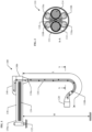
- Fig. 1 shows a side view of an exemplary charging cable assembly 100.
- the exemplary charging cable assembly 100 includes an arm 130 having a fixed end portion 130a and a free end portion 130b, and a charging cable 110 having a first end 110a and a second end 110b.
- the first end 110a of the charging cable 110 is exemplarily connected to the free end portion 130b of the arm 130 such that the charging cable 110 hangs from the arm 130.
- the term “fixed end portion” refers to the portion of the arm at which the arm is supported, and the term “free end portion” refers to the portion of the arm which is not supported.
- the "fixed end portion” may be supported such that the arm is mounted at the fixed end portion to restrict translation, but may be allowed to rotate in at least one degree of freedom.
- portion of the "fixed end portion” and the “free end portion” refers to the respective end portion of the arm, more particularly, the respective end 25% of the arm. In other words, the "fixed end portion” refers to the 25% of the arm at the end which is supported, while the “free end portion” refers to the 25% of the arm at the end which is not supported.
- the arrangement of coolant channels 116 is exemplarily shown as comprising four coolant channels 116 which form two separate circuits for coolant flow, whereby the outbound cooling channels 116a connect at the second end of the charging cable to the respective inbound cooling channels 116b to form each cooling circuit.
- the present disclosure is not limited to any specific arrangement of conductors and coolant channels, and may include any number of conductors, any number of coolant channels, and any configuration of cooling circuits therein.
- the arm 130 may form a rigid, hollow structure through which components may pass through.
- the charging cable 110 may, for example, pass through the arm 130 and continue to a charging station.
- the arm 130 may include a plurality of busbars 134, and each one of the plurality of conductors 114 of the charging cable 110 are electrically connected to each respective one of the plurality of busbars 134. Since the arm 130 is rigid, and may be made to be electrically isolating, a significant length of the charging cable 110 can be replaced with low-resistance busbars 134 which generate significantly less heat at high current throughput, and consequently require no additional cooling.
- the arm 130 may be configured to be mounted to a wall, a ceiling, or a charging station.
- the fixed end portion 130a of the arm 130 may be configured to be mounted to a wall, a ceiling or a charging station.
- the arm 130 may be configured to be mounted to a side surface or a top surface of a charging station.
- the charging cable assembly 100 shown in Fig. 1 the charging cable assembly 100 is exemplarily shown as being attached to a horizontal surface, which would correspond to the top surface of a charging station in a typical installation.
- the charging cable assembly 100 may be mounted to a wall or ceiling, with additional busbars and/or cables connecting the charging cable assembly 100 to the charging station.
- the electric vehicle charging system 300 includes a charging station 320 which includes an electric vehicle supply equipment (EVSE) apparatus 322, and a charging cable assembly 100 according to the first aspect of the present disclosure.
- the electric vehicle charging system 300 in simplest form, may consist of a charging station 320 with a charging cable assembly 100 mounted to the top surface, forming a self-contained electric vehicle charging system 300 having an articulated arm 130 and a liquid cooled charging cable 110 which is cooled by the arm-mounted thermal management unit 140.
Landscapes
- Engineering & Computer Science (AREA)
- Power Engineering (AREA)
- Transportation (AREA)
- Mechanical Engineering (AREA)
- Electric Propulsion And Braking For Vehicles (AREA)
- Charge And Discharge Circuits For Batteries Or The Like (AREA)
Abstract
The present disclosure provides a charging cable assembly 100 comprising an arm 130, a charging cable 110 attached to the arm 130, a charging connector 120 and a thermal management unit 140 configured for cooling the charging cable 110 and/or the charging connector 120 by circulating coolant through a plurality of coolant channels provided in the charging cable 110. The present disclosure further provides an electric vehicle charging system 300 comprising a charging station 320 having an EVSE 322, and a charging cable assembly 100 according to the present disclosure.
Description
- Embodiments of the present disclosure relate to a charging cable assembly suitable for charging electric vehicles, and an electric vehicle charging system having said charging cable assembly. Particularly, embodiments of the present disclosure relate to a liquid-cooled charging cable assembly suitable for high current applications.
- Electrification of transport in general and private electrical vehicles have increased the demand for charging options. Particularly, the demand for faster charging options which reduce charging times, not just for personal electric vehicles but also for heavy-duty commercial electric vehicles, has introduced new challenges. One limiting factor in charging cables for electric vehicles is the heat that is generated when high currents flow through the cable and the electrical connector from the charging station to the battery of a vehicle. The heat may be actively conducted away from the heat sources using liquids.
- European patent application no.
EP 4 134 266 A1 describes an electric vehicle charging system according to the current state of the art, the system having a liquid-cooling system for cooling the charging cable and/or the charging connector. The electric vehicle charging system includes a charging station which houses thermal management unit comprising a vapour-compression refrigeration system. The liquid-cooled charging cable and/or charging connector allows for an electric vehicle to be charged with a higher electric current, without exceeding a temperature limit of the system. - However, with ever-increasing electric charging current, such as a charging current starting at 1500 A and extending up to 3000 A as used in the Megawatt Charging System (MCS) from ABB E-mobility, the limitations of liquid-cooled charging systems of the current state of the art become apparent. Such high charging currents generate more heat, requiring more efficient cooling solutions to operate without exceeding temperature limits. Further, it is desirable to maintain the size and weight of the charging cable and charging connector at manageable levels so that the charging system is easily operable by the user.
- In view of the above challenges and problems arising in the state of the art, an improved electric vehicle charging system which is suitable for high current charging is sought.
- According to a first aspect of the present disclosure, a charging cable assembly for charging an electric vehicle is provided. The charging cable assembly includes an arm, a charging cable having a first end and a second end, the charging cable comprising a plurality of conductors extending from the first end to the second end and a plurality of coolant channels extending from the first end to the second end, wherein the first end of the charging cable is connected to the arm, a charging connector provided at the second end of the charging cable, the charging connector being configured for electrically connecting the charging cable assembly to an electric vehicle, and a thermal management unit mounted on the arm, the thermal management unit being configured for cooling the charging cable and/or the charging connector by circulating coolant through the plurality of coolant channels.
- According to a second aspect of the present disclosure, an electric vehicle charging system is provided. The electric vehicle charging system includes a charging station including an electric vehicle supply equipment (EVSE) apparatus, and a charging cable assembly according to the first aspect.
- The aspects and embodiments of the present disclosure overcome the disadvantages in the current state of the art. By providing a shorter charging cable being supported by an arm, the liquid cooling circuit has a shorter fluid path which has reduced flow losses, allowing for more efficient cooling of the charging cable. Additionally, the shorter cable, i.e. shorter conductors, have a lower overall resistance compared to longer cables, and less heat is generated in the cable. Further, by locating the thermal management unit on the arm instead of within the charging station itself, the charging station can be more compact and simplified, and the components inside the charging station, such as the electric vehicle supply equipment (EVSE), are not subjected to additional heat load by the thermal management unit.
- Further advantages of the charging cable assembly of the present disclosure include that the usability of the charging cable is improved, as the arm can be articulated to move the charging connector into the desired position easily, and the arm supports the weight of the heavy liquid-cooled cable. Additionally, the charging cable assembly provides further protection for the charging cable and charging connector, as the hanging cable may be prevented from laying on the ground when not in use, and damage by a vehicle is avoided.
- Those skilled in the art will recognize additional features and advantages upon reading the following detailed description, and upon viewing the accompanying drawings.
- The components in the figures are not necessarily to scale, instead emphasis being placed upon illustrating the principles of the invention. Moreover, in the figures, like reference numerals designate corresponding parts. In the drawings:
- Fig. 1
- illustrates a schematic side view of a charging cable assembly according to embodiments of the present disclosure;
- Fig. 2
- illustrates a cross-sectional view through section A-A of a charging cable assembly according to embodiments of the present disclosure; and
- Fig. 3
- illustrates a perspective view of an electric vehicle charging system according to embodiments of the present disclosure.
- Reference will now be made in detail to the various embodiments, one or more examples of which are illustrated in each figure. Each example is provided by way of explanation and is not meant as a limitation. For example, features illustrated or described as part of one embodiment can be used on or in conjunction with any other embodiment to yield yet a further embodiment. It is intended that the present disclosure includes such modifications and variations.
- Within the following description of the drawings, the same reference numbers refer to the same or to similar components. Generally, only the differences with respect to the individual embodiments are described. Unless specified otherwise, the description of a part or aspect in one embodiment applies to a corresponding part or aspect in another embodiment as well.
- According to aspects and embodiments of the present disclosure, a charging cable assembly for charging an electric vehicle is provided. Reference will now be made to
Fig. 1 , which shows a side view of an exemplarycharging cable assembly 100. The exemplarycharging cable assembly 100 includes anarm 130 having a fixedend portion 130a and afree end portion 130b, and acharging cable 110 having afirst end 110a and asecond end 110b. Thefirst end 110a of thecharging cable 110 is exemplarily connected to thefree end portion 130b of thearm 130 such that thecharging cable 110 hangs from thearm 130. - In the context of the present disclosure, the term "fixed end portion" refers to the portion of the arm at which the arm is supported, and the term "free end portion" refers to the portion of the arm which is not supported. The "fixed end portion" may be supported such that the arm is mounted at the fixed end portion to restrict translation, but may be allowed to rotate in at least one degree of freedom. The term "portion" of the "fixed end portion" and the "free end portion" refers to the respective end portion of the arm, more particularly, the respective end 25% of the arm. In other words, the "fixed end portion" refers to the 25% of the arm at the end which is supported, while the "free end portion" refers to the 25% of the arm at the end which is not supported.
- The
charging cable 110 includes a plurality of conductors and a plurality of coolant channels extending from thefirst end 110a to thesecond end 110b. A cross-section of an example charging cable is shown inFig. 2 , which exemplarily shows anouter casing 112 of the charging cable and, within theouter casing 112, twoconductors 114 for transmitting electrical current, particularly high-power DC current, to the electric vehicle and a plurality of coolant channels 116 running alongside theconductors 114. Thecharging cable 110 may further include other electrical lines or conductors, such as acommunication lines 118 so that the electric vehicle attached to thecharging cable assembly 100 may communicate with an electric vehicle charging system. The arrangement of coolant channels 116 is exemplarily shown as comprising four coolant channels 116 which form two separate circuits for coolant flow, whereby theoutbound cooling channels 116a connect at the second end of the charging cable to the respectiveinbound cooling channels 116b to form each cooling circuit. However, the present disclosure is not limited to any specific arrangement of conductors and coolant channels, and may include any number of conductors, any number of coolant channels, and any configuration of cooling circuits therein. - The
charging cable assembly 100 further includes acharging connector 120 provided at thesecond end 110b of thecharging cable 110. Thecharging connector 120 is configured for electrically connecting thecharging cable assembly 100 to an electric vehicle. Thecharging connector 120 may include a plurality of terminals, including terminals connected to theconductors 114 and optionally terminals connected to thecommunication lines 118. Thecharging connector 120 may further include coolant channels connected to the coolant channels 116 of the charging cable so that thecharging connector 120 itself may also be cooled. Thecharging connector 120 may have a standard form, such as a Combined Charging System (CCS) Combo 1 or Combo 2 charging connector or an IEC 62196 Type 2 connector. - The
charging cable assembly 100 further includes athermal management unit 140 which is mounted on thearm 130. According to an embodiment, which may be combined with other embodiments described herein, thethermal management unit 140 is mounted at thefree end portion 130b of thearm 130. Preferably, thethermal management unit 140 is on the top side of thearm 130 at thefree end portion 130b of thearm 130. However, the present disclosure is not limited thereto, and thethermal management unit 140 may be mounted at any position on thearm 130. Thethermal management unit 140 is connected to the plurality of coolant channels 116 of the chargingcable 110 so as to cool the chargingcable 110 and/or the chargingconnector 120 by circulating coolant through the plurality of coolant channels 116. - The
thermal management unit 140 may include any suitable active liquid cooling device in the current state of the art. Preferably, thethermal management unit 140 includes a vapour-compression refrigeration system, otherwise known as a chiller. The chiller connects to the coolant channels 116 provided in the chargingcable 110 to form a refrigeration cycle for cooling the chargingcable 110. In the present disclosure, the terms "coolant" and "refrigerant" may be used interchangeably, meaning the liquid which is circulated through the coolant channels 116 to cool the chargingcable 110 and/or the chargingconnector 120. The chiller may include typical components of a refrigeration system, including a compressor for compressing a refrigerant, an air-cooled heat exchanger for cooling the compressed refrigerant, an expansion valve for expanding the refrigerant, and a pump for circulating the refrigerant. These components are preferably contained within an enclosure to form a self-containedthermal management unit 140. - According to an embodiment, which may be combined with other embodiments described herein, the charging
cable assembly 100 may include an arm which has at least two arm segments. Further, the chargingcable assembly 100 may include at least onehinge element 132, so that the arm may be articulated so that the chargingcable 110 may be easily positioned into a charging position near the electric vehicle being charged, or the chargingcable 110 may be easily positioned into a storage position. By including at least two arm sections which are joined with at least onehinge element 132, the arm may be provided with more degrees of freedom so as to articulate into more convenient positions. - With a conventional construction, the
arm 130 may form a rigid, hollow structure through which components may pass through. The chargingcable 110 may, for example, pass through thearm 130 and continue to a charging station. However, in the present disclosure, for providing the electrical current to theconductors 114 of the chargingcable 110, thearm 130 may include a plurality ofbusbars 134, and each one of the plurality ofconductors 114 of the chargingcable 110 are electrically connected to each respective one of the plurality ofbusbars 134. Since thearm 130 is rigid, and may be made to be electrically isolating, a significant length of the chargingcable 110 can be replaced with low-resistance busbars 134 which generate significantly less heat at high current throughput, and consequently require no additional cooling. It follows that thethermal management unit 140 is only required to cool the significantlyshorter charging cable 110 with a significantly shorter coolant circuit, which reduces flow losses compared to a longer coolant circuit and improves the efficiency of thethermal management unit 140, and may also allow thethermal management unit 140 to be made smaller. - According to embodiments, which may be combined with other embodiments described herein, the
arm 130 may be configured to be mounted to a wall, a ceiling, or a charging station. Particularly, thefixed end portion 130a of thearm 130 may be configured to be mounted to a wall, a ceiling or a charging station. More particularly, thearm 130 may be configured to be mounted to a side surface or a top surface of a charging station. In the chargingcable assembly 100 shown inFig. 1 , the chargingcable assembly 100 is exemplarily shown as being attached to a horizontal surface, which would correspond to the top surface of a charging station in a typical installation. However, in cases where multiple chargingcable assemblies 100 are installed for connecting to a consolidated, centralised charging station, the chargingcable assembly 100 may be mounted to a wall or ceiling, with additional busbars and/or cables connecting the chargingcable assembly 100 to the charging station. - In a typical installation, the
arm 130 is installed at a height H above the ground, and the chargingcable 110 attached thereto hangs from thearm 130. According to an embodiment, which may be combined with other embodiments described herein, the chargingcable assembly 100 is positioned such that thearm 130 is at a height H from the ground, and the chargingcable 110 has a length L which is less than the height H. Accordingly, when the chargingcable 110 and chargingconnector 120 are not in use, the charging cable is not left to lay on the ground. The chargingcable 110 and chargingconnector 120 are consequently less likely to be damaged by a vehicle driving over them, and is protected from impact damage from the chargingcable 110 or chargingconnector 120 from hitting the ground after being dropped. - Referring now to
Fig. 3 , according to the second aspect of the present disclosure, an electricvehicle charging system 300 is provided. The electricvehicle charging system 300 includes a chargingstation 320 which includes an electric vehicle supply equipment (EVSE)apparatus 322, and a chargingcable assembly 100 according to the first aspect of the present disclosure. The electricvehicle charging system 300, in simplest form, may consist of a chargingstation 320 with a chargingcable assembly 100 mounted to the top surface, forming a self-contained electricvehicle charging system 300 having an articulatedarm 130 and a liquid cooled chargingcable 110 which is cooled by the arm-mountedthermal management unit 140. - The charging
station 320 may consist of any appropriate charging station in the current state of the art, including AC and DC charging capabilities. The chargingstation 320 includes all necessary components for electric vehicle charging which includes, at a minimum, an electric vehicle supply equipment (EVSE)apparatus 322. However, preferably, the chargingstation 320 would be capable of supplying high current charging to an electric vehicle so as to take full advantage of the liquid-cooled charging cable assembly of the present disclosure. For example, the chargingstation 320 may consist of a Megawatt Charging System charging station from ABB E-mobility suitable for fast-charging of heavy commercial vehicles, which may include anEVSE 322 capable of providing a charging current of 1500 A, or even up to 3000 A. The chargingcable assembly 100 attached to the electricvehicle charging system 300 provides efficient cooling of the chargingcable 110 for high power applications. - Although various exemplary embodiments of the invention have been disclosed, it will be apparent to those skilled in the art that various changes and modifications can be made which will achieve some of the advantages of the invention without departing from the spirit and scope of the invention. It will be obvious to those reasonably skilled in the art that other components performing the same functions may be suitably substituted. It should be mentioned that features explained with reference to a specific figure may be combined with features of other figures, even in those cases in which this has not explicitly been mentioned.
- Spatially relative terms such as "under", "below", "lower", "over", "upper" and the like are used for ease of description to explain the positioning of one element relative to a second element. These terms are intended to encompass different orientations of the device in addition to different orientations than those depicted in the figures. Further, terms such as "first", "second", and the like, are also used to describe various elements, regions, sections, etc. and are also not intended to be limiting. Like terms refer to like elements throughout the description.
- As used herein, the terms "having", "containing", "including", "comprising" and the like are open ended terms that indicate the presence of stated elements or features, but do not preclude additional elements or features. The articles "a", "an" and "the" are intended to include the plural as well as the singular, unless the context clearly indicates otherwise.
- With the above range of variations and applications in mind, it should be understood that the present invention is not limited by the foregoing description, nor is it limited by the accompanying drawings. Instead, the present invention is limited only by the following claims and their legal equivalents.
-
- 100
- Charging cable assembly
- 110
- Charging cable
- 110a
- First end of the charging cable
- 110b
- Second end of the charging cable
- 112
- Outer insulation
- 114
- Conductor
- 116
- Coolant channel
- 116a
- Outbound coolant channel
- 116b
- Inbound coolant channel
- 118
- Communication line
- 120
- Charging connector
- 130
- Arm
- 130a
- Fixed end portion of the arm
- 130b
- Free end portion of the arm
- 132
- Hinge element
- 134
- Busbar
- 140
- Thermal management unit
- 300
- Electric vehicle charging system
- 320
- Charging station
- 322
- EVSE apparatus
- H
- Arm height
- L
- Charging cable length
Claims (13)
- A charging cable assembly (100) for charging an electric vehicle, the charging cable assembly (100) comprising:an arm (130);a charging cable (110) having a first end (110a) and a second end (110b), the charging cable (110) comprising a plurality of conductors (114) extending from the first end (110a) to the second end (110b) and a plurality of coolant channels (116) extending from the first end (110a) to the second end (110b), wherein the first end (110a) of the charging cable (110) is connected to the arm (130);a charging connector (120) provided at the second end (110b) of the charging cable (110), the charging connector (120) being configured for electrically connecting the charging cable assembly (100) to an electric vehicle; anda thermal management unit (140) mounted on the arm (130), the thermal management unit (140) being configured for cooling the charging cable (110) and/or the charging connector (120) by circulating coolant through the plurality of coolant channels (116).
- The charging cable assembly (100) according to claim 1, wherein the arm (130) comprises a plurality of busbars (134), and each one of the plurality of conductors (114) of the charging cable (110) are electrically connected to each respective one of the plurality of busbars (134).
- The charging cable assembly (100) according to any one of claims 1 to 2, wherein the arm (130) comprises a fixed end portion (130a) and a free end portion (130b).
- The charging cable assembly (100) according to claim 3, wherein the thermal management unit (140) is mounted at the free end portion (130b) of the arm (130).
- The charging cable assembly (100) according to any one of claims 3 to 4, wherein the first end (110a) of the charging cable (110) is connected to the arm (130) at the free end portion (130b).
- The charging cable assembly (100) according to any one of claims 1 to 5, wherein the thermal management unit (140) comprises an active liquid cooling device.
- The charging cable assembly (100) according to any one of claims 1 to 5, wherein the thermal management unit (140) comprises a vapour-compression refrigeration system.
- The charging cable assembly (100) according to any one of claims 1 to 7, wherein the arm (130) is configured to be mounted to a wall, a ceiling, or a charging station.
- The charging cable assembly (100) according to any one of claims 1 to 8, wherein the arm (130) comprises at least one hinge element (132).
- The charging cable assembly (100) according to claim 9, wherein the arm (130) comprises at least two arm sections which are joined with the at least one hinge element (132).
- The charging cable assembly (100) according to any one of claims 1 to 10, wherein the charging cable assembly (100) is positioned such that the arm (130) is at a height H from the ground, and the charging cable (110) has a length L which is less than the height H.
- An electric vehicle charging system (300) comprising a charging station (320) comprising an electric vehicle supply equipment (EVSE) apparatus (322), and a charging cable assembly (100) according to any one of claims 1 to 11.
- The electric vehicle charging system (300) according to claim 12, wherein the arm (130) is mounted to the charging station (320).
Priority Applications (1)
| Application Number | Priority Date | Filing Date | Title |
|---|---|---|---|
| EP23189082.3A EP4501700A1 (en) | 2023-08-01 | 2023-08-01 | Charging cable assembly and electric vehicle charging system |
Applications Claiming Priority (1)
| Application Number | Priority Date | Filing Date | Title |
|---|---|---|---|
| EP23189082.3A EP4501700A1 (en) | 2023-08-01 | 2023-08-01 | Charging cable assembly and electric vehicle charging system |
Publications (1)
| Publication Number | Publication Date |
|---|---|
| EP4501700A1 true EP4501700A1 (en) | 2025-02-05 |
Family
ID=87553649
Family Applications (1)
| Application Number | Title | Priority Date | Filing Date |
|---|---|---|---|
| EP23189082.3A Withdrawn EP4501700A1 (en) | 2023-08-01 | 2023-08-01 | Charging cable assembly and electric vehicle charging system |
Country Status (1)
| Country | Link |
|---|---|
| EP (1) | EP4501700A1 (en) |
Citations (4)
| Publication number | Priority date | Publication date | Assignee | Title |
|---|---|---|---|---|
| US5306999A (en) * | 1993-01-15 | 1994-04-26 | Hubbell Incorporated | Electric vehicle charging station |
| US20170028862A1 (en) * | 2015-07-29 | 2017-02-02 | Dr. Ing. H.C. F. Porsche Aktiengesellschaft | Charging station having a charging cable |
| EP4134266A1 (en) | 2021-08-13 | 2023-02-15 | ABB E-mobility B.V. | Electric vehicle charging system |
| EP3708412B1 (en) * | 2019-03-12 | 2023-07-05 | ABB E-mobility B.V. | Charging arrangement for supplying electrical energy to an electrical vehicle |
-
2023
- 2023-08-01 EP EP23189082.3A patent/EP4501700A1/en not_active Withdrawn
Patent Citations (4)
| Publication number | Priority date | Publication date | Assignee | Title |
|---|---|---|---|---|
| US5306999A (en) * | 1993-01-15 | 1994-04-26 | Hubbell Incorporated | Electric vehicle charging station |
| US20170028862A1 (en) * | 2015-07-29 | 2017-02-02 | Dr. Ing. H.C. F. Porsche Aktiengesellschaft | Charging station having a charging cable |
| EP3708412B1 (en) * | 2019-03-12 | 2023-07-05 | ABB E-mobility B.V. | Charging arrangement for supplying electrical energy to an electrical vehicle |
| EP4134266A1 (en) | 2021-08-13 | 2023-02-15 | ABB E-mobility B.V. | Electric vehicle charging system |
Similar Documents
| Publication | Publication Date | Title |
|---|---|---|
| JP7670710B2 (en) | Bidirectional power conversion and charging apparatus for use with electric vehicles - Patents.com | |
| JP3226511U (en) | Device with an input terminal tab connecting a first input terminal tube to a second input terminal tube | |
| KR102667074B1 (en) | Charging cable assembly for electric vehicle | |
| EP3700022A1 (en) | Electrical connector assembly with modular cooling features | |
| US10800276B2 (en) | Electrical charging arrangement with charging socket for vehicle | |
| JP6048572B2 (en) | Uninterruptible power system | |
| EP3793038B1 (en) | Electrical connector assembly | |
| US20200313328A1 (en) | Electrical connector assembly with liquid cooling features | |
| CN110869238A (en) | Electrical storage device for supplying electrical energy to at least one electrically drivable motor vehicle during a charging/discharging process, and retrofit module and operating method | |
| US11440491B2 (en) | Vehicle cooling system and wire harness cooling structure | |
| US12334233B2 (en) | Cooled charging cable | |
| EP3950407A1 (en) | Vehicle-mounted power battery, rechargeable energy storage system, and electric car | |
| KR20210055001A (en) | Charging cable assembly for electric vehicle | |
| CN208754008U (en) | Liquid-cooled charging system for electric automobile | |
| US12476393B2 (en) | Hybrid electric charging inlet | |
| US11837824B2 (en) | Systems, methods, and apparatus useful for busway power distribution | |
| US20230034451A1 (en) | Power cable assembly for a power distribution system having an integrated cooling system | |
| CN114864168A (en) | Cable, rifle and fill electric pile charge | |
| WO2022148763A1 (en) | Charging inlet | |
| JP2021197334A (en) | Cooling device and battery module assembly | |
| KR102240921B1 (en) | Battery pack | |
| CN223378894U (en) | Charging device and charging system | |
| US20260011994A1 (en) | Fluid-cooled busbar assembly for a track busway system | |
| CN212485935U (en) | Novel direct current bus system of container | |
| US20250246862A1 (en) | Active Cooling of Busbars Using Compressed Air |
Legal Events
| Date | Code | Title | Description |
|---|---|---|---|
| PUAI | Public reference made under article 153(3) epc to a published international application that has entered the european phase |
Free format text: ORIGINAL CODE: 0009012 |
|
| STAA | Information on the status of an ep patent application or granted ep patent |
Free format text: STATUS: THE APPLICATION HAS BEEN PUBLISHED |
|
| AK | Designated contracting states |
Kind code of ref document: A1 Designated state(s): AL AT BE BG CH CY CZ DE DK EE ES FI FR GB GR HR HU IE IS IT LI LT LU LV MC ME MK MT NL NO PL PT RO RS SE SI SK SM TR |
|
| STAA | Information on the status of an ep patent application or granted ep patent |
Free format text: STATUS: THE APPLICATION IS DEEMED TO BE WITHDRAWN |
|
| 18D | Application deemed to be withdrawn |
Effective date: 20250806 |