EP4501672A1 - Thermal management assembly with flexible connecting component - Google Patents
Thermal management assembly with flexible connecting component Download PDFInfo
- Publication number
- EP4501672A1 EP4501672A1 EP24182593.4A EP24182593A EP4501672A1 EP 4501672 A1 EP4501672 A1 EP 4501672A1 EP 24182593 A EP24182593 A EP 24182593A EP 4501672 A1 EP4501672 A1 EP 4501672A1
- Authority
- EP
- European Patent Office
- Prior art keywords
- connecting component
- component
- fixing mechanism
- sensor
- flexible connecting
- Prior art date
- Legal status (The legal status is an assumption and is not a legal conclusion. Google has not performed a legal analysis and makes no representation as to the accuracy of the status listed.)
- Granted
Links
Images





Classifications
-
- H—ELECTRICITY
- H05—ELECTRIC TECHNIQUES NOT OTHERWISE PROVIDED FOR
- H05K—PRINTED CIRCUITS; CASINGS OR CONSTRUCTIONAL DETAILS OF ELECTRIC APPARATUS; MANUFACTURE OF ASSEMBLAGES OF ELECTRICAL COMPONENTS
- H05K7/00—Constructional details common to different types of electric apparatus
- H05K7/20—Modifications to facilitate cooling, ventilating, or heating
-
- B—PERFORMING OPERATIONS; TRANSPORTING
- B60—VEHICLES IN GENERAL
- B60H—ARRANGEMENTS OF HEATING, COOLING, VENTILATING OR OTHER AIR-TREATING DEVICES SPECIALLY ADAPTED FOR PASSENGER OR GOODS SPACES OF VEHICLES
- B60H1/00—Heating, cooling or ventilating devices
- B60H1/00485—Valves for air-conditioning devices, e.g. thermostatic valves
-
- F—MECHANICAL ENGINEERING; LIGHTING; HEATING; WEAPONS; BLASTING
- F28—HEAT EXCHANGE IN GENERAL
- F28F—DETAILS OF HEAT-EXCHANGE AND HEAT-TRANSFER APPARATUS, OF GENERAL APPLICATION
- F28F27/00—Control arrangements or safety devices specially adapted for heat-exchange or heat-transfer apparatus
-
- H—ELECTRICITY
- H05—ELECTRIC TECHNIQUES NOT OTHERWISE PROVIDED FOR
- H05K—PRINTED CIRCUITS; CASINGS OR CONSTRUCTIONAL DETAILS OF ELECTRIC APPARATUS; MANUFACTURE OF ASSEMBLAGES OF ELECTRICAL COMPONENTS
- H05K7/00—Constructional details common to different types of electric apparatus
- H05K7/20—Modifications to facilitate cooling, ventilating, or heating
- H05K7/20218—Modifications to facilitate cooling, ventilating, or heating using a liquid coolant without phase change in electronic enclosures
- H05K7/20281—Thermal management, e.g. liquid flow control
-
- B—PERFORMING OPERATIONS; TRANSPORTING
- B60—VEHICLES IN GENERAL
- B60H—ARRANGEMENTS OF HEATING, COOLING, VENTILATING OR OTHER AIR-TREATING DEVICES SPECIALLY ADAPTED FOR PASSENGER OR GOODS SPACES OF VEHICLES
- B60H1/00—Heating, cooling or ventilating devices
- B60H1/00642—Control systems or circuits; Control members or indication devices for heating, cooling or ventilating devices
- B60H1/00735—Control systems or circuits characterised by their input, i.e. by the detection, measurement or calculation of particular conditions, e.g. signal treatment, dynamic models
- B60H1/00792—Arrangement of detectors
-
- F—MECHANICAL ENGINEERING; LIGHTING; HEATING; WEAPONS; BLASTING
- F28—HEAT EXCHANGE IN GENERAL
- F28F—DETAILS OF HEAT-EXCHANGE AND HEAT-TRANSFER APPARATUS, OF GENERAL APPLICATION
- F28F2280/00—Mounting arrangements; Arrangements for facilitating assembling or disassembling of heat exchanger parts
Definitions
- the present invention relates to the field of thermal management technology, and in particular, to a thermal management assembly.
- a sensor and a flow channel component are fixed and detect the temperature, pressure and other parameters of the fluid in the flow channel.
- a control component is located in a box body and electrically connected to the sensor.
- the temperature of thermal management assembly changes greatly when operating.
- the materials of the flow channel component and the box body are usually different.
- the difference between the expansion degree of the flow channel component and the expansion degree of the box body causes relative displacement between the flow channel component and the box body, which can easily cause the electrical connection between the sensor and control component to fail due to disconnection.
- An object of the present invention is to provide a thermal management assembly with reliable connection.
- An embodiment of the present invention provides a thermal management assembly, including:
- one end of the flexible connecting component is electrically connected to the sensor, and another end of the flexible connecting component is electrically connected to the control component, the flexible connecting component is deformable, which reduces the relative displacement between the flow channel component and the box body due to different degrees of expansion when the thermal management assembly is operating.
- the flexible connecting component of the embodiment of the present invention is capable of reducing the stress at the connection between the flexible connecting component and the sensor, and the connection between the flexible connecting component and the control component, thereby making the connection between the flexible connecting component and the sensor, and the connection between the flexible connecting component and the control component reliable.
- first”, “second” and similar words used in the specification and claims of this application do not represent any order, quantity or importance, but are only used to distinguish different components.
- an or “a” and other similar words do not mean a quantity limit, but mean that there is at least one; “multiple” or “a plurality of' means two or more than two.
- front, “rear”, “lower” and/or “upper” and similar words are for ease of description only and are not limited to one location or one spatial orientation.
- the thermal management assembly includes a flow channel component 11, a box body 12, a sensor 13, a control component 14 and a flexible connecting component 15.
- the flow channel component 11 defines a first accommodation space 111 located between a flow channel 112 and the box body 12.
- the sensor 13 includes a sensor body 131.
- the box body 12 defines a second accommodation space 121.
- the sensor body 131 is located in the first accommodation space 111 and/or the second accommodation space 121, and the sensor body 131 and the flow channel component 11 are fixedly connected.
- the senor 13 further includes a detection portion 132.
- the detection portion 132 is located in the flow channel 112 to detect parameters such as pressure and/or temperature of the fluid located in the flow channel 112.
- the control component 14 is located in the second accommodation space 121.
- the control component 14 and the box body 12 are fixedly connected.
- One end of the flexible connecting component 15 is electrically connected to the sensor 13, and another end of the flexible connecting component 15 is electrically connected to the control component 14.
- the temperature changes greatly when the thermal management assembly is operating, and the flow channel component 11 and the box body 12 are made of different materials, so that when the thermal management assembly is operating, the expansion degree of the flow channel component 11 and the expansion degree of the box body 12 are different.
- the flexible connecting component 15 is deformable to reduce the relative displacement between the flow channel component 11 and the box body 12 due to different expansion degrees when the thermal management assembly is operating, thereby reducing the stress borne by the connection between the flexible connecting component 15 and the sensor 13, and the connection between the flexible connecting component 15 and the control component 14. As a result, the connection between the flexible connecting component 15 and the sensor 13, and the connection between the flexible connecting component 15 and the control component 14 are made stable and reliable.
- the flexible connecting component 15 is a flexible circuit board.
- the flexible circuit board has a simple structure and is lightweight, and the flexible circuit board is also convenient for connecting the sensor 13 and the control component 14, so that the flexible connecting component 15 can be installed in the box body 12 with a small size.
- the flexible circuit board is flexible and has a certain degree of rigidity. Therefore, under vibration conditions, the vibration amplitude of the flexible circuit board is small, which is capable of reducing the interference between the flexible connecting component 15 and other components of the thermal management assembly, and can further reduce the stress at the connection between the flexible connecting component 15 and the sensor 13, and the connection between the flexible connecting component 15 and the control component 14. As a result, the connection between the flexible connecting component 15 and the sensor 13, and the connection between the flexible connecting component 15 and the control component 14 are made stable and reliable.
- the thermal management assembly further includes at least two valve cores 16 which are at least partially located in the second accommodation space 121.
- the at least two valve cores 16 are electrically connected to the control component 14.
- the valve cores 16, the control component 14 and the flexible connecting component 15 are integrated to the box body 12, so that the thermal management assembly has a high integration level and is conducive for miniaturization.
- the thermal management assembly further includes a first fixing mechanism 17 and a first connecting component 18.
- the first fixing mechanism 17 is at least partially located in the second accommodation space 121.
- the first fixing mechanism 17 is connected to the box body 12.
- the first fixing mechanism 17 has a substantially U-shaped structure. Two side walls of the U-shaped structure are connected to the box body 12, respectively.
- the flexible connecting component 15 and the sensor 13 are located on two sides of a bottom wall of the U-shaped structure of the first fixing mechanism 17, respectively.
- the flexible connecting component 15 is partially located between the two side walls of the U-shaped structure.
- the first fixing mechanism 17 includes a first wall portion 171 and a second wall portion 172.
- the first wall portion 171 is located at an end of the first fixing mechanism 17 close to the sensor 13.
- the second wall portion 172 is located at an end of the first fixing mechanism 17 close to the flexible connecting component 15.
- the first fixing mechanism 17 has a first wall surface 173 and a second wall surface 174.
- the first fixing mechanism 17 has a first connecting through hole 175 which penetrates from the first wall surface 173 to the second wall surface 174.
- the first connecting component 18 passes through the first connecting through hole 175.
- One end of the first connecting component 18 is electrically connected to the sensor 13, and another end of the first connecting component 18 is electrically connected to the flexible connecting component 15.
- the first connecting through hole 175 plays a positioning role for the assembly of the first connecting component 18 so that two ends of the first connecting component 18 can accurately connect the sensor 13 and the flexible connecting component 15.
- a plurality of first connecting components 18 are provided.
- the plurality of first connecting components 18 are integrated to the first fixing mechanism 17.
- the first connecting components 18 and the first fixing mechanism 17 are injection molded together, which reduces the assembly steps between the first connecting component 18, the sensor 13 and the flexible connecting component 15, and improves the convenience of the first connecting component 18 connecting the sensor 13 and the flexible connecting component 15.
- the first wall portion 171 defines a receiving groove 1711 which is located at a position of the first wall portion 171 close to the sensor 13.
- the receiving groove 1711 is a structure in which part of the first wall portion 171 is recessed toward a side away from the sensor 13.
- the first wall portion 171 includes a peripheral wall 1712 and a bottom wall 1713.
- the peripheral wall 1712 is a groove wall whose peripheral side surrounds the receiving groove 1711.
- the bottom wall 1713 is a groove wall of an end of the receiving groove 1711 away from an opening of the receiving groove 1711.
- the sensor 13 is at least partially located in the receiving groove 1711, and one end of the sensor 13 close to the first fixing mechanism 17 is in contact with the peripheral wall 1712.
- the first wall portion 171 includes a first positioning structure 1714.
- the first positioning structure 1714 is located in the receiving groove 1711.
- the sensor 13 includes a second positioning structure 133.
- the first positioning structure 1714 and the second positioning structure 133 are concave-convexly matched or snap-fitted.
- the first positioning structure 1714 is a structure in which part of the peripheral wall 1712 and/or part of the bottom wall 1713 protrudes toward a side close to the sensor 13.
- the second positioning structure 133 is a positioning notch, and the second positioning structure 133 is located at a position where the sensor 13 is close to the first positioning structure 1714.
- the first positioning structure 1714 is located at the second positioning structure 133.
- This structure plays a positioning role for the assembly of the sensor 13 and the first fixing mechanism 17, thereby facilitating the assembly of the sensor 13 and the first fixing mechanism 17, and making the assembly position of the sensor 13 and the first fixing mechanism 17 accurate.
- this structure can also limit the relative movement between the sensor 13 and the first fixing mechanism 17 to a certain extent, and keep the sensor 13 and the first fixing mechanism 17 in an accurate assembly position, thereby making the connection between the sensor 13 and the first connecting component 18 stable and reliable.
- the first positioning structure 1714 is a structure in which part of the peripheral wall 1712 and/or part of the bottom wall 1713 is recessed toward a side away from the sensor 13.
- the second positioning structure 133 is a structure in which the end of the sensor 13 close to the first fixing mechanism 17 protrudes toward the side close to the first positioning mechanism. Moreover, the second positioning structure 133 is located at a position where the sensor 13 is close to the first positioning structure 1714. The second positioning structure 133 is located at the first positioning structure 1714, so that the assembly position of the sensor 13 and the first fixing mechanism 17 is accurate, and the connection between the sensor 13 and the first connecting component 18 is stable and reliable.
- the peripheral wall 1712 is inclined toward the side close to the sensor 13.
- the peripheral wall 1712 of this structure has the function of guiding the movement direction of the sensor 13, which can improve the convenience of assembling the sensor 13 and the first fixing mechanism 17.
- the peripheral wall 1712 of this structure facilitates guiding the sensor 13 to move in a direction of the expansion pressure, thereby reducing the risk of damage to the sensor 13.
- the sensor 13 includes an elastic connecting component 134.
- the elastic connecting component 134 is located at a position of the sensor 13 close to the first connecting component 18.
- One end of the elastic connecting component 134 is electrically connected to the detection portion 132, and another end of the elastic connecting component 134 is electrically connected to the first connecting component 18.
- the sensor 13 compresses the elastic connecting component 134. That is, the elastic connecting component 134 has a certain elastic pre-tightening force, so that when the thermal management assembly is in the operating state and there is relative displacement between the sensor 13 and the first fixing mechanism 17, the elastic connecting component 134 releases the compression amount, so that the sensor 13 and the first connecting component 18 can maintain a stable connection.
- the sensor 13 can also continue to compress the elastic connecting component 134 so that the sensor 13 and the first connecting component 18 can maintain a stable connection.
- the elastic connecting component 134 is a spring piece.
- the elastic connecting component 134 of this structure can be electrically connected by contact with the first connecting component 18, so that the structure of the electrical connection between the elastic connecting component 134 and the first connecting component 18 is simple and easy to assemble.
- the flexible connecting component 15 includes a first end portion 151 which is located at an end of the flexible connecting component 15 close to the second wall portion 172.
- the first end portion 151 fits the second wall portion 172.
- This structure provides a certain friction force between the first end portion 151 and the second wall portion 172, which is capable of reducing relative movement between the first end portion 151 and the first fixing mechanism 17, and relative movement between the first end portion 151 and the first fixing mechanism 17 leads to the risk of disconnection and failure of the connection between the first end portion 151 and the first connecting component 18.
- the first fixing mechanism 17 includes a first limiting structure 176 which is located at an end of the second wall portion 172 close to the first end portion 151.
- the flexible connecting component 15 includes a second limiting structure 152 which is located at the first end portion 151 close to the first limiting structure 176.
- the first limiting structure 176 and the second limiting structure 152 are concave-convexly matched or snap-fitted.
- the first limiting structure 176 is a limiting structure in which part of the second wall portion 172 protrudes toward the direction close to the first end portion 151.
- the second limiting structure 152 is a limiting hole or a limiting groove.
- the first limiting structure 176 is located at the second limiting structure 152. This structure can limit the relative movement between the first fixing mechanism 17 and the first end portion 151 to a certain extent, reducing the stress at the connection between the flexible connecting component 15 and the first connecting component 18, thereby reducing the risk of disconnection and failure of the electrical connection between the flexible connecting component 15 and the first connecting component 18, further making the connection between the flexible connecting component 15 and the first connecting component 18 stable and reliable.
- the first limiting structure 176 is a cylindrical structure.
- the second limiting structure 152 is a circular hole structure.
- the number of the first limiting structures 176 is two, and the number of the second limiting structures 152 is at least two.
- the cylindrical structure and circular hole structure are easy to process and have low cost.
- the number of the first limiting structure 176 and the second limiting structure 152 is at least two, so that the first limiting structure 176 and the second limiting structure 152 can limit the relative movement between the first fixing mechanism 17 and the flexible connecting component 15 to a certain extent, while the relative rotation between the first fixing mechanism 17 and the flexible connecting component 15 can also be restricted.
- the thermal management assembly further includes a first buffer mechanism 23.
- the first buffer mechanism 23 is located between the first end portion 151 and the second wall portion 172.
- the first buffer mechanism 23 defines a first through hole 231 extending through the first buffer mechanism 23.
- the first through hole 231 is located at a position of the first buffer mechanism 23 close to the first connecting component 18 and the first limiting structure 176.
- the first connecting component 18 and the first limiting structure 176 both pass through the first through hole 231.
- the first buffer mechanism 23 can share the expansion tension force borne by the first end portion 151, thereby improving the safety of the flexible connecting component 15.
- the first limiting structure 176 is a limiting hole or a limiting groove.
- the second limiting structure 152 is a limiting structure in which part of the first end portion 151 protrudes toward the direction close to the second wall portion 172.
- the second limiting structure 152 is located at the first limiting structure 176 to limit the relative movement between the first fixing mechanism 17 and the first end portion 151 to a certain extent.
- one of the first limiting structure 176 and the second limiting structure 152 is a triangular, rectangular or other polygonal cube or cone structure, and a remaining one is a hole structure or groove structure adapted to the triangular, rectangular or other polygonal cube or cone structure, so that the first limiting structure 176 and the second limiting structure 152 can limit the relative movement between the first fixing mechanism 17 and the flexible connecting component 15 to a certain extent, while the relative rotation between the second fixing mechanism 21 and the flexible connecting component 15 can also be restricted.
- the number of the first limiting structure 176 and the number of the second limiting structure 152 may be one or more than three, as long as the limiting can be achieved, which is not limited by the present invention.
- the thermal management assembly further includes an elastic component 19.
- One side of the elastic component 19 in a thickness direction thereof is connected to the first fixing mechanism 17, and another side of the elastic component 19 in the thickness direction thereof is connected to the box body 12.
- the first fixing mechanism 17 includes a protruding structure 177.
- the elastic component 19 has a concave hole 191 in which the protruding structure 177 is located.
- the elastic component 19 has clamping notches 192 which are located at opposite ends of the elastic component 19.
- the box body 12 includes a clamping structure 122 located in the clamping notches 192, and the clamping structure 122 is in contact with the elastic component 19.
- the first fixing mechanism 17 and the box body 12 are capable of compressing or releasing the elastic component 19.
- the deformation generated by the elastic component 19 is capable of reducing the relative displacement between the first fixing mechanism 17 and the box body 12 to a certain extent, so that the assembly position of the first fixing mechanism 17, the sensor 13 and the flexible connecting component 15 is accurate.
- the concave hole 191 of the elastic component 19 can be replaced by a groove.
- the clamping notches 192 of the elastic component 19 can be replaced by clamping holes or clamping grooves.
- the flexible connecting component 15 includes a second end portion 153.
- the second end portion 153 is located at an end of the flexible connecting component 15 close to the control component 14.
- the thermal management assembly further includes a second fixing mechanism 21 and a second connecting component 22.
- the control component 14 and the flexible connecting component 15 are located on two sides of the second fixing mechanism 21, respectively.
- the second fixing mechanism 21 includes a third wall portion 211 and a fourth wall portion 212.
- the third wall portion 211 is located at an end of the second fixing mechanism 21 close to the control component 14.
- the fourth wall portion 212 is located at an end of the second fixing mechanism 21 close to the second end portion 153.
- the second fixing mechanism 21 has a third wall surface 213 and a fourth wall surface 214.
- An end surface of the third wall portion 211 close to the control component 14 is the third wall surface 213.
- An end surface of the fourth wall portion 212 close to the second end portion 153 is the fourth wall surface 214.
- the second fixing mechanism 21 defines a second connecting through hole 215.
- the second connecting through hole 215 penetrates the third wall surface 213 to the fourth wall surface 214.
- the second connecting component 22 passes through the second connecting through hole 215.
- One end of the second connecting component 22 is electrically connected to the control component 14, and another end of the second connecting component 22 is electrically connected to the second end portion 153.
- the second connecting through hole 215 plays a positioning role for the assembly of the second connecting component 22 so that two ends of the second connecting component 22 can be accurately connected to the control component 14 and the flexible connecting component 15.
- a plurality of second connecting components 22 are provided. Integrating the plurality of second connecting components 22 to the second fixing mechanism 21 reduces the assembly steps among the second connecting components 22, the sensor 13 and the flexible connecting component 15, and improves the convenience of connecting the second connecting components 22 to the sensor 13 and to the flexible connecting component 15.
- the second fixing mechanism 21 includes a third limiting structure 216 which is located at an end of the fourth wall portion 212 close to the second end portion 153.
- the flexible connecting component 15 includes a fourth limiting structure 154 which is located at the second end portion 153 close to the third limiting structure 216.
- the third limiting structure 216 and the fourth limiting structure 154 are connected or snap-fitted.
- the third limiting structure 216 is a limiting structure in which part of the second wall portion 172 protrudes toward the direction close to the second end portion 153.
- the fourth limiting structure 154 is a limiting hole or a limiting groove.
- the third limiting structure 216 is located in the fourth limiting structure 154 to limit the relative movement between the second fixing mechanism 21 and the second end portion 153. This structure reduces the risk of disconnection and failure of the electrical connection between the flexible connecting component 15 and the second connecting component 22, further making the connection between the flexible connecting component 15 and the second connecting component 22 stable and reliable.
- the third limiting structure 216 is a cylindrical structure.
- the fourth limiting structure 154 is a circular hole.
- the number of the third limiting structures 216 is two.
- the number of fourth limiting structures 154 is two.
- the cylindrical structure and circular hole structure are easy to process and have low cost.
- the number of the third limiting structure 216 and the number of the fourth limiting structure 154 each are two, so that the third limiting structure 216 and the fourth limiting structure 154 can limit the relative movement between the second fixing mechanism 21 and the flexible connecting component 15 to a certain extent, while the relative rotation between the second fixing mechanism 21 and the flexible connecting component 15 can also be restricted.
- the thermal management assembly further includes a second buffer mechanism 24.
- the second buffer mechanism 24 is located between the second end portion 153 and the fourth wall portion 212.
- the second buffer mechanism 24 defines a second through hole 241 extending through the second buffer mechanism 24 itself.
- the second through hole 241 is located at a position of the second buffer mechanism 24 close to the second connecting component 22 and the third limiting structure 216.
- the second connecting component 22 and the third limiting structure 216 both pass through the second through hole 241.
- the second buffer mechanism 24 can share the expansion tension borne by the second end portion 153, thereby improving the safety of the flexible connecting component 15.
- the third limiting structure 216 is a limiting hole or a limiting groove.
- the fourth limiting structure 154 is a limiting structure in which part of the second end portion 153 protrudes toward the direction close to the second wall portion 172.
- the fourth limiting structure 154 is located at the third limiting structure 216 to limit the relative movement between the second fixing mechanism 21 and the second end portion 153.
- one of the third limiting structure 216 and the fourth limiting structure 154 is a triangular, rectangular or other polygonal cube or cone structure, and a remaining one is a hole structure or groove structure adapted to the triangular, rectangular or other polygonal cube or cone structure, so that the third limiting structure 216 and the fourth limiting structure 154 can limit the relative movement between the second fixing mechanism 21 and the flexible connecting component 15 to a certain extent, while the relative rotation of the second fixing mechanism 21 and the flexible connecting component 15 can also be restricted.
- one end of the flexible connecting component 15 is electrically connected to the sensor 13, and another end of the flexible connecting component 15 is electrically connected to the control component 14.
- the flexible connecting component 15 is capable of reducing the relative displacement between the flow channel component 11 and the box body 12 due to different degrees of expansion when the thermal management assembly is operating, thereby reducing the stress borne by the connection between the flexible connecting component 15 and the sensor 13, and the connection between the flexible connecting component 15 and the control component 14.
- the connection between the flexible connecting component 15 and the sensor 13, and the connection between the flexible connecting component 15 and the control component 14 are made reliable.
- the flexible connecting component 15 is a flexible circuit board.
- the flexible connecting component 15 can be installed on the box body 12 with a smaller size. Moreover, under vibration conditions, the vibration amplitude of the flexible connecting component 15 is small, further making the connection between the flexible connecting component 15 and the sensor 13, and the connection between the flexible connecting component 15 and the control component 14 stable and reliable.
Landscapes
- Engineering & Computer Science (AREA)
- Physics & Mathematics (AREA)
- Thermal Sciences (AREA)
- Microelectronics & Electronic Packaging (AREA)
- Mechanical Engineering (AREA)
- General Engineering & Computer Science (AREA)
- Fire Alarms (AREA)
- Testing Or Calibration Of Command Recording Devices (AREA)
Abstract
Description
- This patent application claims priority of a
Chinese Patent Application No. 202310960704.2, filed on August 1, 2023 - The present invention relates to the field of thermal management technology, and in particular, to a thermal management assembly.
- In a thermal management assembly, a sensor and a flow channel component are fixed and detect the temperature, pressure and other parameters of the fluid in the flow channel. A control component is located in a box body and electrically connected to the sensor. However, the temperature of thermal management assembly changes greatly when operating. The materials of the flow channel component and the box body are usually different. The difference between the expansion degree of the flow channel component and the expansion degree of the box body causes relative displacement between the flow channel component and the box body, which can easily cause the electrical connection between the sensor and control component to fail due to disconnection.
- An object of the present invention is to provide a thermal management assembly with reliable connection.
- An embodiment of the present invention provides a thermal management assembly, including:
- a flow channel component, the flow channel component having a first expansion coefficient;
- a box body, the box body having a second expansion coefficient, the second expansion coefficient being different from the first expansion coefficient;
- a sensor, the sensor and the flow channel component being fixedly connected;
- a control component, the control component and the box body being fixedly connected; and
- a flexible connecting component, one end of the flexible connecting component being electrically connected to the sensor, and another end of the flexible connecting component being electrically connected to the control component.
- In the embodiment of the present invention, one end of the flexible connecting component is electrically connected to the sensor, and another end of the flexible connecting component is electrically connected to the control component, the flexible connecting component is deformable, which reduces the relative displacement between the flow channel component and the box body due to different degrees of expansion when the thermal management assembly is operating. The flexible connecting component of the embodiment of the present invention is capable of reducing the stress at the connection between the flexible connecting component and the sensor, and the connection between the flexible connecting component and the control component, thereby making the connection between the flexible connecting component and the sensor, and the connection between the flexible connecting component and the control component reliable.
-
-
FIG. 1 is a schematic perspective structural view of a thermal management assembly in accordance with an embodiment of the present invention; -
FIG. 2 is an exploded view of the thermal management assembly in accordance with the embodiment of the present invention; -
FIG. 3 is an exploded schematic view of a box body and a sensor assembly in accordance with the embodiment of the present invention; -
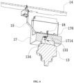
FIG. 4 is a schematic cross-sectional view of a sensor, a flexible connecting component, and a control component assembly in accordance with the embodiment of the present invention; -
FIG. 5 is an assembly schematic view of the sensor, the flexible connecting component, and the control component assembly in accordance with the embodiment of the present invention; -
FIG. 6 is an exploded cross-sectional view of the sensor, a first fixing mechanism, and the flexible connecting component in accordance with the embodiment of the present invention; -
FIG. 7 is an exploded schematic view of the first fixing mechanism, an elastic component, a box body, etc., in accordance with the embodiment of the present invention; -
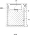
FIG. 8 is a schematic cross-sectional view of the first fixing mechanism, the elastic component, and the box body in accordance with the embodiment of the present invention; and -
FIG. 9 is an exploded schematic view of the control component, a second fixing mechanism, the flexible connecting component, etc., in accordance with the embodiment of the present invention. - Exemplary embodiments will be described in detail here, examples of which are shown in drawings. When referring to the drawings below, unless otherwise indicated, same numerals in different drawings represent the same or similar elements. The examples described in the following exemplary embodiments do not represent all embodiments consistent with this application. Rather, they are merely examples of devices and methods consistent with some aspects of the application as detailed in the appended claims.
- The terminology used in this application is only for the purpose of describing particular embodiments, and is not intended to limit this application. The singular forms "a", "said", and "the" used in this application and the appended claims are also intended to include plural forms unless the context clearly indicates other meanings.
- It should be understood that the terms "first", "second" and similar words used in the specification and claims of this application do not represent any order, quantity or importance, but are only used to distinguish different components. Similarly, "an" or "a" and other similar words do not mean a quantity limit, but mean that there is at least one; "multiple" or "a plurality of' means two or more than two. Unless otherwise noted, "front", "rear", "lower" and/or "upper" and similar words are for ease of description only and are not limited to one location or one spatial orientation. Similar words such as "include" or "comprise" mean that elements or objects appear before "include" or "comprise" cover elements or objects listed after "include" or "comprise" and their equivalents, and do not exclude other elements or objects. The term "a plurality of" mentioned in the present invention includes two or more.
- Hereinafter, some embodiments of the present invention will be described in detail with reference to the accompanying drawings. In the case of no conflict, the following embodiments and features in the embodiments can be combined with each other.
- According to a specific embodiment of a thermal management assembly of the present invention, as shown in
FIG. 1 to FIG. 3 , the thermal management assembly includes aflow channel component 11, abox body 12, asensor 13, acontrol component 14 and aflexible connecting component 15. Theflow channel component 11 defines afirst accommodation space 111 located between a flow channel 112 and thebox body 12. Thesensor 13 includes asensor body 131. Thebox body 12 defines asecond accommodation space 121. Thesensor body 131 is located in thefirst accommodation space 111 and/or thesecond accommodation space 121, and thesensor body 131 and theflow channel component 11 are fixedly connected. - In some possible embodiments, referring to
FIG. 1 , thesensor 13 further includes adetection portion 132. Thedetection portion 132 is located in the flow channel 112 to detect parameters such as pressure and/or temperature of the fluid located in the flow channel 112. - As shown in
FIG. 2 to FIG. 5 , thecontrol component 14 is located in thesecond accommodation space 121. Thecontrol component 14 and thebox body 12 are fixedly connected. One end of the flexible connectingcomponent 15 is electrically connected to thesensor 13, and another end of the flexible connectingcomponent 15 is electrically connected to thecontrol component 14. The temperature changes greatly when the thermal management assembly is operating, and theflow channel component 11 and thebox body 12 are made of different materials, so that when the thermal management assembly is operating, the expansion degree of theflow channel component 11 and the expansion degree of thebox body 12 are different. Theflexible connecting component 15 is deformable to reduce the relative displacement between theflow channel component 11 and thebox body 12 due to different expansion degrees when the thermal management assembly is operating, thereby reducing the stress borne by the connection between the flexible connectingcomponent 15 and thesensor 13, and the connection between the flexible connectingcomponent 15 and thecontrol component 14. As a result, the connection between the flexible connectingcomponent 15 and thesensor 13, and the connection between the flexible connectingcomponent 15 and thecontrol component 14 are made stable and reliable. - In this embodiment, the flexible connecting
component 15 is a flexible circuit board. The flexible circuit board has a simple structure and is lightweight, and the flexible circuit board is also convenient for connecting thesensor 13 and thecontrol component 14, so that theflexible connecting component 15 can be installed in thebox body 12 with a small size. The flexible circuit board is flexible and has a certain degree of rigidity. Therefore, under vibration conditions, the vibration amplitude of the flexible circuit board is small, which is capable of reducing the interference between the flexible connectingcomponent 15 and other components of the thermal management assembly, and can further reduce the stress at the connection between the flexible connectingcomponent 15 and thesensor 13, and the connection between the flexible connectingcomponent 15 and thecontrol component 14. As a result, the connection between the flexible connectingcomponent 15 and thesensor 13, and the connection between the flexible connectingcomponent 15 and thecontrol component 14 are made stable and reliable. - As shown in
FIG. 2 andFIG. 3 , the thermal management assembly further includes at least twovalve cores 16 which are at least partially located in thesecond accommodation space 121. The at least twovalve cores 16 are electrically connected to thecontrol component 14. In this embodiment, thevalve cores 16, thecontrol component 14 and theflexible connecting component 15 are integrated to thebox body 12, so that the thermal management assembly has a high integration level and is conducive for miniaturization. - As shown in
FIG. 3 ,FIG. 4 andFIG. 6 , the thermal management assembly further includes afirst fixing mechanism 17 and a first connectingcomponent 18. Thefirst fixing mechanism 17 is at least partially located in thesecond accommodation space 121. Thefirst fixing mechanism 17 is connected to thebox body 12. - In this embodiment, the
first fixing mechanism 17 has a substantially U-shaped structure. Two side walls of the U-shaped structure are connected to thebox body 12, respectively. The flexible connectingcomponent 15 and thesensor 13 are located on two sides of a bottom wall of the U-shaped structure of thefirst fixing mechanism 17, respectively. The flexible connectingcomponent 15 is partially located between the two side walls of the U-shaped structure. Thefirst fixing mechanism 17 includes afirst wall portion 171 and asecond wall portion 172. Thefirst wall portion 171 is located at an end of thefirst fixing mechanism 17 close to thesensor 13. Thesecond wall portion 172 is located at an end of thefirst fixing mechanism 17 close to the flexible connectingcomponent 15. Thefirst fixing mechanism 17 has afirst wall surface 173 and asecond wall surface 174. An end surface of thefirst wall portion 171 close to thesensor 13 is thefirst wall surface 173. An end surface of thesecond wall portion 172 close to thecontrol component 14 is thesecond wall surface 174. Thefirst fixing mechanism 17 has a first connecting throughhole 175 which penetrates from thefirst wall surface 173 to thesecond wall surface 174. The first connectingcomponent 18 passes through the first connecting throughhole 175. One end of the first connectingcomponent 18 is electrically connected to thesensor 13, and another end of the first connectingcomponent 18 is electrically connected to the flexible connectingcomponent 15. The first connecting throughhole 175 plays a positioning role for the assembly of the first connectingcomponent 18 so that two ends of the first connectingcomponent 18 can accurately connect thesensor 13 and the flexible connectingcomponent 15. - In this embodiment, a plurality of first connecting
components 18 are provided. The plurality of first connectingcomponents 18 are integrated to thefirst fixing mechanism 17. For example, the first connectingcomponents 18 and thefirst fixing mechanism 17 are injection molded together, which reduces the assembly steps between the first connectingcomponent 18, thesensor 13 and the flexible connectingcomponent 15, and improves the convenience of the first connectingcomponent 18 connecting thesensor 13 and the flexible connectingcomponent 15. - As shown in
FIG. 4 andFIG. 6 , thefirst wall portion 171 defines a receivinggroove 1711 which is located at a position of thefirst wall portion 171 close to thesensor 13. The receivinggroove 1711 is a structure in which part of thefirst wall portion 171 is recessed toward a side away from thesensor 13. Thefirst wall portion 171 includes aperipheral wall 1712 and abottom wall 1713. Theperipheral wall 1712 is a groove wall whose peripheral side surrounds the receivinggroove 1711. Thebottom wall 1713 is a groove wall of an end of the receivinggroove 1711 away from an opening of the receivinggroove 1711. Thesensor 13 is at least partially located in the receivinggroove 1711, and one end of thesensor 13 close to thefirst fixing mechanism 17 is in contact with theperipheral wall 1712. - The
first wall portion 171 includes afirst positioning structure 1714. Thefirst positioning structure 1714 is located in the receivinggroove 1711. Thesensor 13 includes asecond positioning structure 133. Thefirst positioning structure 1714 and thesecond positioning structure 133 are concave-convexly matched or snap-fitted. - In some possible embodiments, the
first positioning structure 1714 is a structure in which part of theperipheral wall 1712 and/or part of thebottom wall 1713 protrudes toward a side close to thesensor 13. Thesecond positioning structure 133 is a positioning notch, and thesecond positioning structure 133 is located at a position where thesensor 13 is close to thefirst positioning structure 1714. Thefirst positioning structure 1714 is located at thesecond positioning structure 133. This structure plays a positioning role for the assembly of thesensor 13 and thefirst fixing mechanism 17, thereby facilitating the assembly of thesensor 13 and thefirst fixing mechanism 17, and making the assembly position of thesensor 13 and thefirst fixing mechanism 17 accurate. Moreover, this structure can also limit the relative movement between thesensor 13 and thefirst fixing mechanism 17 to a certain extent, and keep thesensor 13 and thefirst fixing mechanism 17 in an accurate assembly position, thereby making the connection between thesensor 13 and the first connectingcomponent 18 stable and reliable. - In some other possible embodiments, the
first positioning structure 1714 is a structure in which part of theperipheral wall 1712 and/or part of thebottom wall 1713 is recessed toward a side away from thesensor 13. Thesecond positioning structure 133 is a structure in which the end of thesensor 13 close to thefirst fixing mechanism 17 protrudes toward the side close to the first positioning mechanism. Moreover, thesecond positioning structure 133 is located at a position where thesensor 13 is close to thefirst positioning structure 1714. Thesecond positioning structure 133 is located at thefirst positioning structure 1714, so that the assembly position of thesensor 13 and thefirst fixing mechanism 17 is accurate, and the connection between thesensor 13 and the first connectingcomponent 18 is stable and reliable. - As shown in
FIG. 4 andFIG. 6 , along a direction from the opening of the receivinggroove 1711 to thebottom wall 1713, theperipheral wall 1712 is inclined toward the side close to thesensor 13. Theperipheral wall 1712 of this structure has the function of guiding the movement direction of thesensor 13, which can improve the convenience of assembling thesensor 13 and thefirst fixing mechanism 17. At the same time, when the thermal management assembly is in operating condition, due to the difference between the expansion degree of theflow channel component 11 and the expansion degree of thebox body 12, when relative movement occurs between thesensor 13 and thefirst fixing mechanism 17, theperipheral wall 1712 of this structure facilitates guiding thesensor 13 to move in a direction of the expansion pressure, thereby reducing the risk of damage to thesensor 13. - As shown in
FIG. 4 andFIG. 6 , thesensor 13 includes an elastic connectingcomponent 134. The elastic connectingcomponent 134 is located at a position of thesensor 13 close to the first connectingcomponent 18. One end of the elastic connectingcomponent 134 is electrically connected to thedetection portion 132, and another end of the elastic connectingcomponent 134 is electrically connected to the first connectingcomponent 18. - In this embodiment, during assembly, the
sensor 13 compresses the elastic connectingcomponent 134. That is, the elastic connectingcomponent 134 has a certain elastic pre-tightening force, so that when the thermal management assembly is in the operating state and there is relative displacement between thesensor 13 and thefirst fixing mechanism 17, the elastic connectingcomponent 134 releases the compression amount, so that thesensor 13 and the first connectingcomponent 18 can maintain a stable connection. Of course, when the thermal management assembly is in operating condition and there is relative displacement between thesensor 13 and thefirst fixing mechanism 17, thesensor 13 can also continue to compress the elastic connectingcomponent 134 so that thesensor 13 and the first connectingcomponent 18 can maintain a stable connection. - In this embodiment, the elastic connecting
component 134 is a spring piece. The elastic connectingcomponent 134 of this structure can be electrically connected by contact with the first connectingcomponent 18, so that the structure of the electrical connection between the elastic connectingcomponent 134 and the first connectingcomponent 18 is simple and easy to assemble. - As shown in
FIG. 4 andFIG. 6 , the flexible connectingcomponent 15 includes afirst end portion 151 which is located at an end of the flexible connectingcomponent 15 close to thesecond wall portion 172. Thefirst end portion 151 fits thesecond wall portion 172. This structure provides a certain friction force between thefirst end portion 151 and thesecond wall portion 172, which is capable of reducing relative movement between thefirst end portion 151 and thefirst fixing mechanism 17, and relative movement between thefirst end portion 151 and thefirst fixing mechanism 17 leads to the risk of disconnection and failure of the connection between thefirst end portion 151 and the first connectingcomponent 18. - The
first fixing mechanism 17 includes a first limitingstructure 176 which is located at an end of thesecond wall portion 172 close to thefirst end portion 151. The flexible connectingcomponent 15 includes a second limitingstructure 152 which is located at thefirst end portion 151 close to the first limitingstructure 176. The first limitingstructure 176 and the second limitingstructure 152 are concave-convexly matched or snap-fitted. - In this embodiment, the first limiting
structure 176 is a limiting structure in which part of thesecond wall portion 172 protrudes toward the direction close to thefirst end portion 151. The second limitingstructure 152 is a limiting hole or a limiting groove. The first limitingstructure 176 is located at the second limitingstructure 152. This structure can limit the relative movement between thefirst fixing mechanism 17 and thefirst end portion 151 to a certain extent, reducing the stress at the connection between the flexible connectingcomponent 15 and the first connectingcomponent 18, thereby reducing the risk of disconnection and failure of the electrical connection between the flexible connectingcomponent 15 and the first connectingcomponent 18, further making the connection between the flexible connectingcomponent 15 and the first connectingcomponent 18 stable and reliable. - In this embodiment, the first limiting
structure 176 is a cylindrical structure. The second limitingstructure 152 is a circular hole structure. The number of the first limitingstructures 176 is two, and the number of the second limitingstructures 152 is at least two. The cylindrical structure and circular hole structure are easy to process and have low cost. The number of the first limitingstructure 176 and the second limitingstructure 152 is at least two, so that the first limitingstructure 176 and the second limitingstructure 152 can limit the relative movement between thefirst fixing mechanism 17 and the flexible connectingcomponent 15 to a certain extent, while the relative rotation between thefirst fixing mechanism 17 and the flexible connectingcomponent 15 can also be restricted. - In this embodiment, as shown in
FIG. 6 , the thermal management assembly further includes afirst buffer mechanism 23. Thefirst buffer mechanism 23 is located between thefirst end portion 151 and thesecond wall portion 172. Along a thickness direction of thefirst buffer mechanism 23, thefirst buffer mechanism 23 defines a first throughhole 231 extending through thefirst buffer mechanism 23. The first throughhole 231 is located at a position of thefirst buffer mechanism 23 close to the first connectingcomponent 18 and the first limitingstructure 176. The first connectingcomponent 18 and the first limitingstructure 176 both pass through the first throughhole 231. When the thermal management assembly is in operating condition, thefirst buffer mechanism 23 can share the expansion tension force borne by thefirst end portion 151, thereby improving the safety of the flexible connectingcomponent 15. - In some other possible embodiments, the first limiting
structure 176 is a limiting hole or a limiting groove. The second limitingstructure 152 is a limiting structure in which part of thefirst end portion 151 protrudes toward the direction close to thesecond wall portion 172. The second limitingstructure 152 is located at the first limitingstructure 176 to limit the relative movement between thefirst fixing mechanism 17 and thefirst end portion 151 to a certain extent. - In some other possible embodiments, one of the first limiting
structure 176 and the second limitingstructure 152 is a triangular, rectangular or other polygonal cube or cone structure, and a remaining one is a hole structure or groove structure adapted to the triangular, rectangular or other polygonal cube or cone structure, so that the first limitingstructure 176 and the second limitingstructure 152 can limit the relative movement between thefirst fixing mechanism 17 and the flexible connectingcomponent 15 to a certain extent, while the relative rotation between thesecond fixing mechanism 21 and the flexible connectingcomponent 15 can also be restricted. The number of the first limitingstructure 176 and the number of the second limitingstructure 152 may be one or more than three, as long as the limiting can be achieved, which is not limited by the present invention. - As shown in
FIG. 3 ,FIG. 7 andFIG. 8 , the thermal management assembly further includes anelastic component 19. One side of theelastic component 19 in a thickness direction thereof is connected to thefirst fixing mechanism 17, and another side of theelastic component 19 in the thickness direction thereof is connected to thebox body 12. - Specifically, the
first fixing mechanism 17 includes a protrudingstructure 177. Theelastic component 19 has aconcave hole 191 in which the protrudingstructure 177 is located. Theelastic component 19 has clampingnotches 192 which are located at opposite ends of theelastic component 19. Thebox body 12 includes a clampingstructure 122 located in the clampingnotches 192, and the clampingstructure 122 is in contact with theelastic component 19. When the thermal management assembly is in operating condition, the difference between the expansion degree of thebox body 12 and the expansion degree of theflow channel component 11 results in relative displacement between thefirst fixing mechanism 17 and thebox body 12. Thefirst fixing mechanism 17 and thebox body 12 are capable of compressing or releasing theelastic component 19. The deformation generated by theelastic component 19 is capable of reducing the relative displacement between thefirst fixing mechanism 17 and thebox body 12 to a certain extent, so that the assembly position of thefirst fixing mechanism 17, thesensor 13 and the flexible connectingcomponent 15 is accurate. - It is understandable that the
concave hole 191 of theelastic component 19 can be replaced by a groove. At the same time, the clampingnotches 192 of theelastic component 19 can be replaced by clamping holes or clamping grooves. - As shown in
FIG. 5 andFIG. 9 , the flexible connectingcomponent 15 includes asecond end portion 153. Thesecond end portion 153 is located at an end of the flexible connectingcomponent 15 close to thecontrol component 14. The thermal management assembly further includes asecond fixing mechanism 21 and a second connectingcomponent 22. Thecontrol component 14 and the flexible connectingcomponent 15 are located on two sides of thesecond fixing mechanism 21, respectively. Thesecond fixing mechanism 21 includes athird wall portion 211 and afourth wall portion 212. Thethird wall portion 211 is located at an end of thesecond fixing mechanism 21 close to thecontrol component 14. Thefourth wall portion 212 is located at an end of thesecond fixing mechanism 21 close to thesecond end portion 153. Thesecond fixing mechanism 21 has athird wall surface 213 and afourth wall surface 214. An end surface of thethird wall portion 211 close to thecontrol component 14 is thethird wall surface 213. An end surface of thefourth wall portion 212 close to thesecond end portion 153 is thefourth wall surface 214. - The
second fixing mechanism 21 defines a second connecting throughhole 215. The second connecting throughhole 215 penetrates thethird wall surface 213 to thefourth wall surface 214. The second connectingcomponent 22 passes through the second connecting throughhole 215. One end of the second connectingcomponent 22 is electrically connected to thecontrol component 14, and another end of the second connectingcomponent 22 is electrically connected to thesecond end portion 153. The second connecting throughhole 215 plays a positioning role for the assembly of the second connectingcomponent 22 so that two ends of the second connectingcomponent 22 can be accurately connected to thecontrol component 14 and the flexible connectingcomponent 15. In this embodiment, a plurality of second connectingcomponents 22 are provided. Integrating the plurality of second connectingcomponents 22 to thesecond fixing mechanism 21 reduces the assembly steps among the second connectingcomponents 22, thesensor 13 and the flexible connectingcomponent 15, and improves the convenience of connecting the second connectingcomponents 22 to thesensor 13 and to the flexible connectingcomponent 15. - The
second fixing mechanism 21 includes a third limitingstructure 216 which is located at an end of thefourth wall portion 212 close to thesecond end portion 153. The flexible connectingcomponent 15 includes a fourth limitingstructure 154 which is located at thesecond end portion 153 close to the third limitingstructure 216. The third limitingstructure 216 and the fourth limitingstructure 154 are connected or snap-fitted. - In this embodiment, the third limiting
structure 216 is a limiting structure in which part of thesecond wall portion 172 protrudes toward the direction close to thesecond end portion 153. The fourth limitingstructure 154 is a limiting hole or a limiting groove. The third limitingstructure 216 is located in the fourth limitingstructure 154 to limit the relative movement between thesecond fixing mechanism 21 and thesecond end portion 153. This structure reduces the risk of disconnection and failure of the electrical connection between the flexible connectingcomponent 15 and the second connectingcomponent 22, further making the connection between the flexible connectingcomponent 15 and the second connectingcomponent 22 stable and reliable. - In this embodiment, the third limiting
structure 216 is a cylindrical structure. The fourth limitingstructure 154 is a circular hole. The number of the third limitingstructures 216 is two. The number of fourth limitingstructures 154 is two. The cylindrical structure and circular hole structure are easy to process and have low cost. The number of the third limitingstructure 216 and the number of the fourth limitingstructure 154 each are two, so that the third limitingstructure 216 and the fourth limitingstructure 154 can limit the relative movement between thesecond fixing mechanism 21 and the flexible connectingcomponent 15 to a certain extent, while the relative rotation between thesecond fixing mechanism 21 and the flexible connectingcomponent 15 can also be restricted. - In this embodiment, as shown in
FIG. 9 , the thermal management assembly further includes asecond buffer mechanism 24. Thesecond buffer mechanism 24 is located between thesecond end portion 153 and thefourth wall portion 212. Along a thickness direction of thesecond buffer mechanism 24, thesecond buffer mechanism 24 defines a second throughhole 241 extending through thesecond buffer mechanism 24 itself. The second throughhole 241 is located at a position of thesecond buffer mechanism 24 close to the second connectingcomponent 22 and the third limitingstructure 216. The second connectingcomponent 22 and the third limitingstructure 216 both pass through the second throughhole 241. When the thermal management assembly is in the operating state, thesecond buffer mechanism 24 can share the expansion tension borne by thesecond end portion 153, thereby improving the safety of the flexible connectingcomponent 15. - In some other possible embodiments, the third limiting
structure 216 is a limiting hole or a limiting groove. The fourth limitingstructure 154 is a limiting structure in which part of thesecond end portion 153 protrudes toward the direction close to thesecond wall portion 172. The fourth limitingstructure 154 is located at the third limitingstructure 216 to limit the relative movement between thesecond fixing mechanism 21 and thesecond end portion 153. - In some other possible embodiments, one of the third limiting
structure 216 and the fourth limitingstructure 154 is a triangular, rectangular or other polygonal cube or cone structure, and a remaining one is a hole structure or groove structure adapted to the triangular, rectangular or other polygonal cube or cone structure, so that the third limitingstructure 216 and the fourth limitingstructure 154 can limit the relative movement between thesecond fixing mechanism 21 and the flexible connectingcomponent 15 to a certain extent, while the relative rotation of thesecond fixing mechanism 21 and the flexible connectingcomponent 15 can also be restricted. - In the present invention, one end of the flexible connecting
component 15 is electrically connected to thesensor 13, and another end of the flexible connectingcomponent 15 is electrically connected to thecontrol component 14. The flexible connectingcomponent 15 is capable of reducing the relative displacement between theflow channel component 11 and thebox body 12 due to different degrees of expansion when the thermal management assembly is operating, thereby reducing the stress borne by the connection between the flexible connectingcomponent 15 and thesensor 13, and the connection between the flexible connectingcomponent 15 and thecontrol component 14. As a result, the connection between the flexible connectingcomponent 15 and thesensor 13, and the connection between the flexible connectingcomponent 15 and thecontrol component 14 are made reliable. At the same time, the flexible connectingcomponent 15 is a flexible circuit board. The flexible connectingcomponent 15 can be installed on thebox body 12 with a smaller size. Moreover, under vibration conditions, the vibration amplitude of the flexible connectingcomponent 15 is small, further making the connection between the flexible connectingcomponent 15 and thesensor 13, and the connection between the flexible connectingcomponent 15 and thecontrol component 14 stable and reliable. - The above embodiments are only used to illustrate the present invention and not to limit the technical solutions described in the present invention. The understanding of this specification should be based on those skilled in the art. Descriptions of directions, although they have been described in detail in the above-mentioned embodiments of the present invention, those skilled in the art should understand that modifications or equivalent substitutions can still be made to the application, and all technical solutions and improvements that do not depart from the spirit and scope of the application should be covered by the claims of the application.
Claims (10)
- A thermal management assembly, characterized by comprising:a flow channel component (11), the flow channel component (11) having a first expansion coefficient;a box body (12), the box body (12) having a second expansion coefficient, the second expansion coefficient being different from the first expansion coefficient;a sensor (13), the sensor (13) and the flow channel component (11) being fixedly connected;a control component (14), the control component (14) and the box body (12) being fixedly connected; anda flexible connecting component (15), one end of the flexible connecting component (15) being electrically connected to the sensor (13), and another end of the flexible connecting component (15) being electrically connected to the control component (14).
- The thermal management assembly according to claim 1, wherein the flexible connecting component (15) is a flexible circuit board.
- The thermal management assembly according to claim 1 or 2, further comprising a first fixing mechanism (17) and a first connecting component (18), the first fixing mechanism (17) being connected to the box body (12), the flexible connecting component (15) and the sensor (13) being located on two sides of the first fixing mechanism (17), respectively;
wherein the first fixing mechanism (17) defines a first connecting through hole (175), the first connecting component (18) passes through the first connecting through hole (175), one end of the first connecting component (18) is electrically connected to the sensor (13), and another end of the first connecting component (18) is electrically connected to the flexible connecting component (15). - The thermal management assembly according to claim 3, wherein the first fixing mechanism (17) defines a receiving groove (1711), the first fixing mechanism (17) comprises a peripheral wall (1712) and a bottom wall (1713), the peripheral wall (1712) is a groove wall whose peripheral side surrounds the receiving groove (1711), the bottom wall (1713) is a groove wall at an end of the receiving groove (1711) away from an opening of the receiving groove (1711);the sensor (13) is at least partially located in the receiving groove (1711), and the sensor (13) fits the peripheral wall (1712);the first fixing mechanism (17) comprises a first positioning structure (1714), the sensor (13) comprises a second positioning structure (133), the first positioning structure (1714) and the second positioning structure (133) are concave-convexly matched or snap-fitted.
- The thermal management assembly according to claim 4, wherein along a direction from the opening of the receiving groove (1711) to the bottom wall (1713), the peripheral wall (1712) is inclined toward a side close to the sensor (13).
- The thermal management assembly according to claim 4, wherein the sensor (13) comprises a detection portion (132) and an elastic connecting component (134); one end of the elastic connecting component (134) is electrically connected to the detection portion (132), and another end of the elastic connecting component (134) is electrically connected to the first connecting component (18).
- The thermal management assembly according to claim 3, wherein the first fixing mechanism (17) comprises a first limiting structure (176), the first limiting structure (176) is located at one end of the first fixing mechanism (17) close to the flexible connecting component (15);the flexible connecting component (15) comprises a second limiting structure (152), the second limiting structure (152) is located at a position of the flexible connecting component (15) close to the first limiting structure (176);the first limiting structure (176) and the second limiting structure (152) are concave-convexly matched or snap-fitted.
- The thermal management assembly according to claim 3, further comprising an elastic component (19), one side of the elastic component (19) along a thickness direction thereof being connected to the first fixing mechanism (17), and another side of the elastic component (19) along the thickness direction thereof being connected to the box body (12).
- The thermal management assembly according to claim 1 or 2, further comprising a second fixing mechanism (21) and a second connecting component (22); wherein the control component (14) and the flexible connecting component (15) are located on two sides of the second fixing mechanism (21), respectively;the second fixing mechanism (21) defines a second connecting through hole (215), the second connecting component (22) is located in the second connecting through hole (215), one end of the second connecting component (22) is electrically connected to the control component (14), and another end of the second connecting component (22) is electrically connected to the flexible connecting component (15);the second fixing mechanism (21) comprises a third limiting structure (216), the third limiting structure (216) is located at one end of the second fixing mechanism (21) close to the flexible connecting component (15);the flexible connecting component (15) comprises a fourth limiting structure (154), the fourth limiting structure (154) is located at a position of the flexible connecting component (15) close to the third limiting structure (216);the third limiting structure (216) and the fourth limiting structure (154) are concave-convexly matched or snap-fitted.
- The thermal management assembly according to claim 1 or 2, further comprising at least two valve cores (16) which are in contact with the control component (14).
Applications Claiming Priority (1)
| Application Number | Priority Date | Filing Date | Title |
|---|---|---|---|
| CN202310960704.2A CN117119749A (en) | 2023-08-01 | 2023-08-01 | Thermal management assembly |
Publications (2)
| Publication Number | Publication Date |
|---|---|
| EP4501672A1 true EP4501672A1 (en) | 2025-02-05 |
| EP4501672B1 EP4501672B1 (en) | 2026-03-25 |
Family
ID=88795643
Family Applications (1)
| Application Number | Title | Priority Date | Filing Date |
|---|---|---|---|
| EP24182593.4A Active EP4501672B1 (en) | 2023-08-01 | 2024-06-17 | Thermal management assembly with flexible connecting component |
Country Status (3)
| Country | Link |
|---|---|
| US (1) | US20260009608A1 (en) |
| EP (1) | EP4501672B1 (en) |
| CN (1) | CN117119749A (en) |
Citations (3)
| Publication number | Priority date | Publication date | Assignee | Title |
|---|---|---|---|---|
| US6909607B2 (en) * | 2002-01-16 | 2005-06-21 | Rockwell Automation Technologies, Inc. | Thermally matched fluid cooled power converter |
| CN211233423U (en) * | 2019-07-25 | 2020-08-11 | 杭州三花研究院有限公司 | Thermal management assembly and thermal management system |
| CN115123111A (en) * | 2021-03-26 | 2022-09-30 | 马勒国际有限公司 | Method for operating a thermal management module |
Family Cites Families (2)
| Publication number | Priority date | Publication date | Assignee | Title |
|---|---|---|---|---|
| JP5605243B2 (en) * | 2011-01-31 | 2014-10-15 | 日本精機株式会社 | Display device |
| CN111121522B (en) * | 2020-01-09 | 2025-03-18 | 中核能源科技有限公司 | A heat exchanger with a thermal displacement compensation support mechanism |
-
2023
- 2023-08-01 CN CN202310960704.2A patent/CN117119749A/en active Pending
-
2024
- 2024-06-17 EP EP24182593.4A patent/EP4501672B1/en active Active
- 2024-07-07 US US18/765,327 patent/US20260009608A1/en active Pending
Patent Citations (3)
| Publication number | Priority date | Publication date | Assignee | Title |
|---|---|---|---|---|
| US6909607B2 (en) * | 2002-01-16 | 2005-06-21 | Rockwell Automation Technologies, Inc. | Thermally matched fluid cooled power converter |
| CN211233423U (en) * | 2019-07-25 | 2020-08-11 | 杭州三花研究院有限公司 | Thermal management assembly and thermal management system |
| CN115123111A (en) * | 2021-03-26 | 2022-09-30 | 马勒国际有限公司 | Method for operating a thermal management module |
Also Published As
| Publication number | Publication date |
|---|---|
| EP4501672B1 (en) | 2026-03-25 |
| US20260009608A1 (en) | 2026-01-08 |
| CN117119749A (en) | 2023-11-24 |
Similar Documents
| Publication | Publication Date | Title |
|---|---|---|
| US7156675B2 (en) | Coaxial connector with a switch | |
| JP4381432B2 (en) | Double-sided connector | |
| KR102113741B1 (en) | Fuel pump module | |
| US10283907B2 (en) | Floating connector and electronic device module | |
| CN114323336A (en) | Temperature sensor installation structure and temperature sensor | |
| US20070032113A1 (en) | Connection terminal and a connection terminal assembly and method for assembling the connection terminal | |
| EP4501672A1 (en) | Thermal management assembly with flexible connecting component | |
| KR20220077887A (en) | Electric connector for circuit board and electric connector assembly | |
| US10617019B2 (en) | Board holding apparatus | |
| US20120114286A1 (en) | Connector assemblies having mating sides moved by fluidic coupling mechanisms | |
| CN112086795B (en) | Electrical connector and electrical connector assembly | |
| US20240332837A1 (en) | Printed circuit board arrangement | |
| JP7814461B2 (en) | Movable Connector | |
| JP4772892B2 (en) | Double-sided connector | |
| US20100105218A1 (en) | Electrical connector for receiving cpu | |
| US7837512B1 (en) | Audio jack connector | |
| US6435890B2 (en) | Movable structure for connectors | |
| EP2750253A1 (en) | Connector | |
| EP4102651A1 (en) | Terminal | |
| CN113964568B (en) | Current holding clamp | |
| JPH03164704A (en) | Float structure of plug-in connector | |
| KR102398228B1 (en) | Housing terminal | |
| KR20220061753A (en) | A signal transfer assembly and a pressure sensor unit using the same | |
| US12451642B2 (en) | Sealing installation device and connector assembly | |
| CN222267651U (en) | Piezoelectric injection valve system |
Legal Events
| Date | Code | Title | Description |
|---|---|---|---|
| PUAI | Public reference made under article 153(3) epc to a published international application that has entered the european phase |
Free format text: ORIGINAL CODE: 0009012 |
|
| STAA | Information on the status of an ep patent application or granted ep patent |
Free format text: STATUS: THE APPLICATION HAS BEEN PUBLISHED |
|
| AK | Designated contracting states |
Kind code of ref document: A1 Designated state(s): AL AT BE BG CH CY CZ DE DK EE ES FI FR GB GR HR HU IE IS IT LI LT LU LV MC ME MK MT NL NO PL PT RO RS SE SI SK SM TR |
|
| STAA | Information on the status of an ep patent application or granted ep patent |
Free format text: STATUS: REQUEST FOR EXAMINATION WAS MADE |
|
| 17P | Request for examination filed |
Effective date: 20250717 |
|
| GRAP | Despatch of communication of intention to grant a patent |
Free format text: ORIGINAL CODE: EPIDOSNIGR1 |
|
| STAA | Information on the status of an ep patent application or granted ep patent |
Free format text: STATUS: GRANT OF PATENT IS INTENDED |
|
| RIC1 | Information provided on ipc code assigned before grant |
Ipc: B60H 1/00 20060101AFI20251014BHEP |
|
| INTG | Intention to grant announced |
Effective date: 20251105 |
|
| GRAS | Grant fee paid |
Free format text: ORIGINAL CODE: EPIDOSNIGR3 |
|
| GRAA | (expected) grant |
Free format text: ORIGINAL CODE: 0009210 |
|
| STAA | Information on the status of an ep patent application or granted ep patent |
Free format text: STATUS: THE PATENT HAS BEEN GRANTED |
|
| AK | Designated contracting states |
Kind code of ref document: B1 Designated state(s): AL AT BE BG CH CY CZ DE DK EE ES FI FR GB GR HR HU IE IS IT LI LT LU LV MC ME MK MT NL NO PL PT RO RS SE SI SK SM TR |
|
| REG | Reference to a national code |
Ref country code: CH Ref legal event code: F10 Free format text: ST27 STATUS EVENT CODE: U-0-0-F10-F00 (AS PROVIDED BY THE NATIONAL OFFICE) Effective date: 20260325 Ref country code: GB Ref legal event code: FG4D |
|
| REG | Reference to a national code |
Ref country code: DE Ref legal event code: R096 Ref document number: 602024003381 Country of ref document: DE |
|
| REG | Reference to a national code |
Ref country code: IE Ref legal event code: FG4D |