EP4501597A1 - Consolidating thermoplastic material with induction heating coil and heating plate(s) - Google Patents
Consolidating thermoplastic material with induction heating coil and heating plate(s) Download PDFInfo
- Publication number
- EP4501597A1 EP4501597A1 EP24179384.3A EP24179384A EP4501597A1 EP 4501597 A1 EP4501597 A1 EP 4501597A1 EP 24179384 A EP24179384 A EP 24179384A EP 4501597 A1 EP4501597 A1 EP 4501597A1
- Authority
- EP
- European Patent Office
- Prior art keywords
- thermoplastic
- metal plate
- patch
- aircraft component
- stack
- Prior art date
- Legal status (The legal status is an assumption and is not a legal conclusion. Google has not performed a legal analysis and makes no representation as to the accuracy of the status listed.)
- Granted
Links
Images


Classifications
-
- B—PERFORMING OPERATIONS; TRANSPORTING
- B64—AIRCRAFT; AVIATION; COSMONAUTICS
- B64F—GROUND OR AIRCRAFT-CARRIER-DECK INSTALLATIONS SPECIALLY ADAPTED FOR USE IN CONNECTION WITH AIRCRAFT; DESIGNING, MANUFACTURING, ASSEMBLING, CLEANING, MAINTAINING OR REPAIRING AIRCRAFT, NOT OTHERWISE PROVIDED FOR; HANDLING, TRANSPORTING, TESTING OR INSPECTING AIRCRAFT COMPONENTS, NOT OTHERWISE PROVIDED FOR
- B64F5/00—Designing, manufacturing, assembling, cleaning, maintaining or repairing aircraft, not otherwise provided for; Handling, transporting, testing or inspecting aircraft components, not otherwise provided for
- B64F5/40—Maintaining or repairing aircraft
-
- B—PERFORMING OPERATIONS; TRANSPORTING
- B29—WORKING OF PLASTICS; WORKING OF SUBSTANCES IN A PLASTIC STATE IN GENERAL
- B29C—SHAPING OR JOINING OF PLASTICS; SHAPING OF MATERIAL IN A PLASTIC STATE, NOT OTHERWISE PROVIDED FOR; AFTER-TREATMENT OF THE SHAPED PRODUCTS, e.g. REPAIRING
- B29C73/00—Repairing of articles made from plastics or substances in a plastic state, e.g. of articles shaped or produced by using techniques covered by this subclass or subclass B29D
- B29C73/04—Repairing of articles made from plastics or substances in a plastic state, e.g. of articles shaped or produced by using techniques covered by this subclass or subclass B29D using preformed elements
- B29C73/10—Repairing of articles made from plastics or substances in a plastic state, e.g. of articles shaped or produced by using techniques covered by this subclass or subclass B29D using preformed elements using patches sealing on the surface of the article
- B29C73/12—Apparatus therefor, e.g. for applying
-
- B—PERFORMING OPERATIONS; TRANSPORTING
- B29—WORKING OF PLASTICS; WORKING OF SUBSTANCES IN A PLASTIC STATE IN GENERAL
- B29C—SHAPING OR JOINING OF PLASTICS; SHAPING OF MATERIAL IN A PLASTIC STATE, NOT OTHERWISE PROVIDED FOR; AFTER-TREATMENT OF THE SHAPED PRODUCTS, e.g. REPAIRING
- B29C65/00—Joining or sealing of preformed parts, e.g. welding of plastics materials; Apparatus therefor
- B29C65/02—Joining or sealing of preformed parts, e.g. welding of plastics materials; Apparatus therefor by heating, with or without pressure
- B29C65/18—Joining or sealing of preformed parts, e.g. welding of plastics materials; Apparatus therefor by heating, with or without pressure using heated tools
-
- B—PERFORMING OPERATIONS; TRANSPORTING
- B29—WORKING OF PLASTICS; WORKING OF SUBSTANCES IN A PLASTIC STATE IN GENERAL
- B29C—SHAPING OR JOINING OF PLASTICS; SHAPING OF MATERIAL IN A PLASTIC STATE, NOT OTHERWISE PROVIDED FOR; AFTER-TREATMENT OF THE SHAPED PRODUCTS, e.g. REPAIRING
- B29C65/00—Joining or sealing of preformed parts, e.g. welding of plastics materials; Apparatus therefor
- B29C65/02—Joining or sealing of preformed parts, e.g. welding of plastics materials; Apparatus therefor by heating, with or without pressure
- B29C65/18—Joining or sealing of preformed parts, e.g. welding of plastics materials; Apparatus therefor by heating, with or without pressure using heated tools
- B29C65/24—Joining or sealing of preformed parts, e.g. welding of plastics materials; Apparatus therefor by heating, with or without pressure using heated tools characterised by the means for heating the tool
- B29C65/30—Electrical means
- B29C65/32—Induction
-
- B—PERFORMING OPERATIONS; TRANSPORTING
- B29—WORKING OF PLASTICS; WORKING OF SUBSTANCES IN A PLASTIC STATE IN GENERAL
- B29C—SHAPING OR JOINING OF PLASTICS; SHAPING OF MATERIAL IN A PLASTIC STATE, NOT OTHERWISE PROVIDED FOR; AFTER-TREATMENT OF THE SHAPED PRODUCTS, e.g. REPAIRING
- B29C65/00—Joining or sealing of preformed parts, e.g. welding of plastics materials; Apparatus therefor
- B29C65/02—Joining or sealing of preformed parts, e.g. welding of plastics materials; Apparatus therefor by heating, with or without pressure
- B29C65/34—Joining or sealing of preformed parts, e.g. welding of plastics materials; Apparatus therefor by heating, with or without pressure using heated elements which remain in the joint, e.g. "verlorenes Schweisselement"
- B29C65/36—Joining or sealing of preformed parts, e.g. welding of plastics materials; Apparatus therefor by heating, with or without pressure using heated elements which remain in the joint, e.g. "verlorenes Schweisselement" heated by induction
- B29C65/3604—Joining or sealing of preformed parts, e.g. welding of plastics materials; Apparatus therefor by heating, with or without pressure using heated elements which remain in the joint, e.g. "verlorenes Schweisselement" heated by induction characterised by the type of elements heated by induction which remain in the joint
- B29C65/3608—Joining or sealing of preformed parts, e.g. welding of plastics materials; Apparatus therefor by heating, with or without pressure using heated elements which remain in the joint, e.g. "verlorenes Schweisselement" heated by induction characterised by the type of elements heated by induction which remain in the joint comprising single particles, e.g. fillers or discontinuous fibre-reinforcements
- B29C65/3616—Joining or sealing of preformed parts, e.g. welding of plastics materials; Apparatus therefor by heating, with or without pressure using heated elements which remain in the joint, e.g. "verlorenes Schweisselement" heated by induction characterised by the type of elements heated by induction which remain in the joint comprising single particles, e.g. fillers or discontinuous fibre-reinforcements comprising discontinuous fibre-reinforcements
-
- B—PERFORMING OPERATIONS; TRANSPORTING
- B29—WORKING OF PLASTICS; WORKING OF SUBSTANCES IN A PLASTIC STATE IN GENERAL
- B29C—SHAPING OR JOINING OF PLASTICS; SHAPING OF MATERIAL IN A PLASTIC STATE, NOT OTHERWISE PROVIDED FOR; AFTER-TREATMENT OF THE SHAPED PRODUCTS, e.g. REPAIRING
- B29C65/00—Joining or sealing of preformed parts, e.g. welding of plastics materials; Apparatus therefor
- B29C65/02—Joining or sealing of preformed parts, e.g. welding of plastics materials; Apparatus therefor by heating, with or without pressure
- B29C65/34—Joining or sealing of preformed parts, e.g. welding of plastics materials; Apparatus therefor by heating, with or without pressure using heated elements which remain in the joint, e.g. "verlorenes Schweisselement"
- B29C65/36—Joining or sealing of preformed parts, e.g. welding of plastics materials; Apparatus therefor by heating, with or without pressure using heated elements which remain in the joint, e.g. "verlorenes Schweisselement" heated by induction
- B29C65/3604—Joining or sealing of preformed parts, e.g. welding of plastics materials; Apparatus therefor by heating, with or without pressure using heated elements which remain in the joint, e.g. "verlorenes Schweisselement" heated by induction characterised by the type of elements heated by induction which remain in the joint
- B29C65/3636—Joining or sealing of preformed parts, e.g. welding of plastics materials; Apparatus therefor by heating, with or without pressure using heated elements which remain in the joint, e.g. "verlorenes Schweisselement" heated by induction characterised by the type of elements heated by induction which remain in the joint comprising independent continuous fibre-reinforcements
-
- B—PERFORMING OPERATIONS; TRANSPORTING
- B29—WORKING OF PLASTICS; WORKING OF SUBSTANCES IN A PLASTIC STATE IN GENERAL
- B29C—SHAPING OR JOINING OF PLASTICS; SHAPING OF MATERIAL IN A PLASTIC STATE, NOT OTHERWISE PROVIDED FOR; AFTER-TREATMENT OF THE SHAPED PRODUCTS, e.g. REPAIRING
- B29C65/00—Joining or sealing of preformed parts, e.g. welding of plastics materials; Apparatus therefor
- B29C65/02—Joining or sealing of preformed parts, e.g. welding of plastics materials; Apparatus therefor by heating, with or without pressure
- B29C65/34—Joining or sealing of preformed parts, e.g. welding of plastics materials; Apparatus therefor by heating, with or without pressure using heated elements which remain in the joint, e.g. "verlorenes Schweisselement"
- B29C65/36—Joining or sealing of preformed parts, e.g. welding of plastics materials; Apparatus therefor by heating, with or without pressure using heated elements which remain in the joint, e.g. "verlorenes Schweisselement" heated by induction
- B29C65/3604—Joining or sealing of preformed parts, e.g. welding of plastics materials; Apparatus therefor by heating, with or without pressure using heated elements which remain in the joint, e.g. "verlorenes Schweisselement" heated by induction characterised by the type of elements heated by induction which remain in the joint
- B29C65/364—Joining or sealing of preformed parts, e.g. welding of plastics materials; Apparatus therefor by heating, with or without pressure using heated elements which remain in the joint, e.g. "verlorenes Schweisselement" heated by induction characterised by the type of elements heated by induction which remain in the joint being a woven or non-woven fabric or being a mesh
-
- B—PERFORMING OPERATIONS; TRANSPORTING
- B29—WORKING OF PLASTICS; WORKING OF SUBSTANCES IN A PLASTIC STATE IN GENERAL
- B29C—SHAPING OR JOINING OF PLASTICS; SHAPING OF MATERIAL IN A PLASTIC STATE, NOT OTHERWISE PROVIDED FOR; AFTER-TREATMENT OF THE SHAPED PRODUCTS, e.g. REPAIRING
- B29C65/00—Joining or sealing of preformed parts, e.g. welding of plastics materials; Apparatus therefor
- B29C65/02—Joining or sealing of preformed parts, e.g. welding of plastics materials; Apparatus therefor by heating, with or without pressure
- B29C65/34—Joining or sealing of preformed parts, e.g. welding of plastics materials; Apparatus therefor by heating, with or without pressure using heated elements which remain in the joint, e.g. "verlorenes Schweisselement"
- B29C65/36—Joining or sealing of preformed parts, e.g. welding of plastics materials; Apparatus therefor by heating, with or without pressure using heated elements which remain in the joint, e.g. "verlorenes Schweisselement" heated by induction
- B29C65/3672—Joining or sealing of preformed parts, e.g. welding of plastics materials; Apparatus therefor by heating, with or without pressure using heated elements which remain in the joint, e.g. "verlorenes Schweisselement" heated by induction characterised by the composition of the elements heated by induction which remain in the joint
- B29C65/3684—Joining or sealing of preformed parts, e.g. welding of plastics materials; Apparatus therefor by heating, with or without pressure using heated elements which remain in the joint, e.g. "verlorenes Schweisselement" heated by induction characterised by the composition of the elements heated by induction which remain in the joint being non-metallic
-
- B—PERFORMING OPERATIONS; TRANSPORTING
- B29—WORKING OF PLASTICS; WORKING OF SUBSTANCES IN A PLASTIC STATE IN GENERAL
- B29C—SHAPING OR JOINING OF PLASTICS; SHAPING OF MATERIAL IN A PLASTIC STATE, NOT OTHERWISE PROVIDED FOR; AFTER-TREATMENT OF THE SHAPED PRODUCTS, e.g. REPAIRING
- B29C65/00—Joining or sealing of preformed parts, e.g. welding of plastics materials; Apparatus therefor
- B29C65/72—Joining or sealing of preformed parts, e.g. welding of plastics materials; Apparatus therefor by combined operations or combined techniques, e.g. welding and stitching
-
- B—PERFORMING OPERATIONS; TRANSPORTING
- B29—WORKING OF PLASTICS; WORKING OF SUBSTANCES IN A PLASTIC STATE IN GENERAL
- B29C—SHAPING OR JOINING OF PLASTICS; SHAPING OF MATERIAL IN A PLASTIC STATE, NOT OTHERWISE PROVIDED FOR; AFTER-TREATMENT OF THE SHAPED PRODUCTS, e.g. REPAIRING
- B29C66/00—General aspects of processes or apparatus for joining preformed parts
- B29C66/01—General aspects dealing with the joint area or with the area to be joined
- B29C66/05—Particular design of joint configurations
- B29C66/10—Particular design of joint configurations particular design of the joint cross-sections
- B29C66/11—Joint cross-sections comprising a single joint-segment, i.e. one of the parts to be joined comprising a single joint-segment in the joint cross-section
- B29C66/112—Single lapped joints
- B29C66/1122—Single lap to lap joints, i.e. overlap joints
-
- B—PERFORMING OPERATIONS; TRANSPORTING
- B29—WORKING OF PLASTICS; WORKING OF SUBSTANCES IN A PLASTIC STATE IN GENERAL
- B29C—SHAPING OR JOINING OF PLASTICS; SHAPING OF MATERIAL IN A PLASTIC STATE, NOT OTHERWISE PROVIDED FOR; AFTER-TREATMENT OF THE SHAPED PRODUCTS, e.g. REPAIRING
- B29C66/00—General aspects of processes or apparatus for joining preformed parts
- B29C66/50—General aspects of joining tubular articles; General aspects of joining long products, i.e. bars or profiled elements; General aspects of joining single elements to tubular articles, hollow articles or bars; General aspects of joining several hollow-preforms to form hollow or tubular articles
- B29C66/51—Joining tubular articles, profiled elements or bars; Joining single elements to tubular articles, hollow articles or bars; Joining several hollow-preforms to form hollow or tubular articles
- B29C66/53—Joining single elements to tubular articles, hollow articles or bars
- B29C66/532—Joining single elements to the wall of tubular articles, hollow articles or bars
-
- B—PERFORMING OPERATIONS; TRANSPORTING
- B29—WORKING OF PLASTICS; WORKING OF SUBSTANCES IN A PLASTIC STATE IN GENERAL
- B29C—SHAPING OR JOINING OF PLASTICS; SHAPING OF MATERIAL IN A PLASTIC STATE, NOT OTHERWISE PROVIDED FOR; AFTER-TREATMENT OF THE SHAPED PRODUCTS, e.g. REPAIRING
- B29C66/00—General aspects of processes or apparatus for joining preformed parts
- B29C66/70—General aspects of processes or apparatus for joining preformed parts characterised by the composition, physical properties or the structure of the material of the parts to be joined; Joining with non-plastics material
- B29C66/72—General aspects of processes or apparatus for joining preformed parts characterised by the composition, physical properties or the structure of the material of the parts to be joined; Joining with non-plastics material characterised by the structure of the material of the parts to be joined
- B29C66/721—Fibre-reinforced materials
-
- B—PERFORMING OPERATIONS; TRANSPORTING
- B29—WORKING OF PLASTICS; WORKING OF SUBSTANCES IN A PLASTIC STATE IN GENERAL
- B29C—SHAPING OR JOINING OF PLASTICS; SHAPING OF MATERIAL IN A PLASTIC STATE, NOT OTHERWISE PROVIDED FOR; AFTER-TREATMENT OF THE SHAPED PRODUCTS, e.g. REPAIRING
- B29C66/00—General aspects of processes or apparatus for joining preformed parts
- B29C66/70—General aspects of processes or apparatus for joining preformed parts characterised by the composition, physical properties or the structure of the material of the parts to be joined; Joining with non-plastics material
- B29C66/72—General aspects of processes or apparatus for joining preformed parts characterised by the composition, physical properties or the structure of the material of the parts to be joined; Joining with non-plastics material characterised by the structure of the material of the parts to be joined
- B29C66/721—Fibre-reinforced materials
- B29C66/7212—Fibre-reinforced materials characterised by the composition of the fibres
-
- B—PERFORMING OPERATIONS; TRANSPORTING
- B29—WORKING OF PLASTICS; WORKING OF SUBSTANCES IN A PLASTIC STATE IN GENERAL
- B29C—SHAPING OR JOINING OF PLASTICS; SHAPING OF MATERIAL IN A PLASTIC STATE, NOT OTHERWISE PROVIDED FOR; AFTER-TREATMENT OF THE SHAPED PRODUCTS, e.g. REPAIRING
- B29C66/00—General aspects of processes or apparatus for joining preformed parts
- B29C66/70—General aspects of processes or apparatus for joining preformed parts characterised by the composition, physical properties or the structure of the material of the parts to be joined; Joining with non-plastics material
- B29C66/72—General aspects of processes or apparatus for joining preformed parts characterised by the composition, physical properties or the structure of the material of the parts to be joined; Joining with non-plastics material characterised by the structure of the material of the parts to be joined
- B29C66/721—Fibre-reinforced materials
- B29C66/7214—Fibre-reinforced materials characterised by the length of the fibres
- B29C66/72141—Fibres of continuous length
-
- B—PERFORMING OPERATIONS; TRANSPORTING
- B29—WORKING OF PLASTICS; WORKING OF SUBSTANCES IN A PLASTIC STATE IN GENERAL
- B29C—SHAPING OR JOINING OF PLASTICS; SHAPING OF MATERIAL IN A PLASTIC STATE, NOT OTHERWISE PROVIDED FOR; AFTER-TREATMENT OF THE SHAPED PRODUCTS, e.g. REPAIRING
- B29C66/00—General aspects of processes or apparatus for joining preformed parts
- B29C66/70—General aspects of processes or apparatus for joining preformed parts characterised by the composition, physical properties or the structure of the material of the parts to be joined; Joining with non-plastics material
- B29C66/72—General aspects of processes or apparatus for joining preformed parts characterised by the composition, physical properties or the structure of the material of the parts to be joined; Joining with non-plastics material characterised by the structure of the material of the parts to be joined
- B29C66/721—Fibre-reinforced materials
- B29C66/7214—Fibre-reinforced materials characterised by the length of the fibres
- B29C66/72143—Fibres of discontinuous lengths
-
- B—PERFORMING OPERATIONS; TRANSPORTING
- B29—WORKING OF PLASTICS; WORKING OF SUBSTANCES IN A PLASTIC STATE IN GENERAL
- B29C—SHAPING OR JOINING OF PLASTICS; SHAPING OF MATERIAL IN A PLASTIC STATE, NOT OTHERWISE PROVIDED FOR; AFTER-TREATMENT OF THE SHAPED PRODUCTS, e.g. REPAIRING
- B29C66/00—General aspects of processes or apparatus for joining preformed parts
- B29C66/70—General aspects of processes or apparatus for joining preformed parts characterised by the composition, physical properties or the structure of the material of the parts to be joined; Joining with non-plastics material
- B29C66/73—General aspects of processes or apparatus for joining preformed parts characterised by the composition, physical properties or the structure of the material of the parts to be joined; Joining with non-plastics material characterised by the intensive physical properties of the material of the parts to be joined, by the optical properties of the material of the parts to be joined, by the extensive physical properties of the parts to be joined, by the state of the material of the parts to be joined or by the material of the parts to be joined being a thermoplastic or a thermoset
- B29C66/739—General aspects of processes or apparatus for joining preformed parts characterised by the composition, physical properties or the structure of the material of the parts to be joined; Joining with non-plastics material characterised by the intensive physical properties of the material of the parts to be joined, by the optical properties of the material of the parts to be joined, by the extensive physical properties of the parts to be joined, by the state of the material of the parts to be joined or by the material of the parts to be joined being a thermoplastic or a thermoset characterised by the material of the parts to be joined being a thermoplastic or a thermoset
- B29C66/7392—General aspects of processes or apparatus for joining preformed parts characterised by the composition, physical properties or the structure of the material of the parts to be joined; Joining with non-plastics material characterised by the intensive physical properties of the material of the parts to be joined, by the optical properties of the material of the parts to be joined, by the extensive physical properties of the parts to be joined, by the state of the material of the parts to be joined or by the material of the parts to be joined being a thermoplastic or a thermoset characterised by the material of the parts to be joined being a thermoplastic or a thermoset characterised by the material of at least one of the parts being a thermoplastic
- B29C66/73921—General aspects of processes or apparatus for joining preformed parts characterised by the composition, physical properties or the structure of the material of the parts to be joined; Joining with non-plastics material characterised by the intensive physical properties of the material of the parts to be joined, by the optical properties of the material of the parts to be joined, by the extensive physical properties of the parts to be joined, by the state of the material of the parts to be joined or by the material of the parts to be joined being a thermoplastic or a thermoset characterised by the material of the parts to be joined being a thermoplastic or a thermoset characterised by the material of at least one of the parts being a thermoplastic characterised by the materials of both parts being thermoplastics
-
- B—PERFORMING OPERATIONS; TRANSPORTING
- B29—WORKING OF PLASTICS; WORKING OF SUBSTANCES IN A PLASTIC STATE IN GENERAL
- B29C—SHAPING OR JOINING OF PLASTICS; SHAPING OF MATERIAL IN A PLASTIC STATE, NOT OTHERWISE PROVIDED FOR; AFTER-TREATMENT OF THE SHAPED PRODUCTS, e.g. REPAIRING
- B29C66/00—General aspects of processes or apparatus for joining preformed parts
- B29C66/80—General aspects of machine operations or constructions and parts thereof
- B29C66/81—General aspects of the pressing elements, i.e. the elements applying pressure on the parts to be joined in the area to be joined, e.g. the welding jaws or clamps
- B29C66/812—General aspects of the pressing elements, i.e. the elements applying pressure on the parts to be joined in the area to be joined, e.g. the welding jaws or clamps characterised by the composition, by the structure, by the intensive physical properties or by the optical properties of the material constituting the pressing elements, e.g. constituting the welding jaws or clamps
- B29C66/8122—General aspects of the pressing elements, i.e. the elements applying pressure on the parts to be joined in the area to be joined, e.g. the welding jaws or clamps characterised by the composition, by the structure, by the intensive physical properties or by the optical properties of the material constituting the pressing elements, e.g. constituting the welding jaws or clamps characterised by the composition of the material constituting the pressing elements, e.g. constituting the welding jaws or clamps
-
- B—PERFORMING OPERATIONS; TRANSPORTING
- B29—WORKING OF PLASTICS; WORKING OF SUBSTANCES IN A PLASTIC STATE IN GENERAL
- B29C—SHAPING OR JOINING OF PLASTICS; SHAPING OF MATERIAL IN A PLASTIC STATE, NOT OTHERWISE PROVIDED FOR; AFTER-TREATMENT OF THE SHAPED PRODUCTS, e.g. REPAIRING
- B29C66/00—General aspects of processes or apparatus for joining preformed parts
- B29C66/80—General aspects of machine operations or constructions and parts thereof
- B29C66/81—General aspects of the pressing elements, i.e. the elements applying pressure on the parts to be joined in the area to be joined, e.g. the welding jaws or clamps
- B29C66/814—General aspects of the pressing elements, i.e. the elements applying pressure on the parts to be joined in the area to be joined, e.g. the welding jaws or clamps characterised by the design of the pressing elements, e.g. of the welding jaws or clamps
- B29C66/8145—General aspects of the pressing elements, i.e. the elements applying pressure on the parts to be joined in the area to be joined, e.g. the welding jaws or clamps characterised by the design of the pressing elements, e.g. of the welding jaws or clamps characterised by the constructional aspects of the pressing elements, e.g. of the welding jaws or clamps
- B29C66/81455—General aspects of the pressing elements, i.e. the elements applying pressure on the parts to be joined in the area to be joined, e.g. the welding jaws or clamps characterised by the design of the pressing elements, e.g. of the welding jaws or clamps characterised by the constructional aspects of the pressing elements, e.g. of the welding jaws or clamps being a fluid inflatable bag or bladder, a diaphragm or a vacuum bag for applying isostatic pressure
-
- B—PERFORMING OPERATIONS; TRANSPORTING
- B29—WORKING OF PLASTICS; WORKING OF SUBSTANCES IN A PLASTIC STATE IN GENERAL
- B29C—SHAPING OR JOINING OF PLASTICS; SHAPING OF MATERIAL IN A PLASTIC STATE, NOT OTHERWISE PROVIDED FOR; AFTER-TREATMENT OF THE SHAPED PRODUCTS, e.g. REPAIRING
- B29C73/00—Repairing of articles made from plastics or substances in a plastic state, e.g. of articles shaped or produced by using techniques covered by this subclass or subclass B29D
- B29C73/04—Repairing of articles made from plastics or substances in a plastic state, e.g. of articles shaped or produced by using techniques covered by this subclass or subclass B29D using preformed elements
- B29C73/10—Repairing of articles made from plastics or substances in a plastic state, e.g. of articles shaped or produced by using techniques covered by this subclass or subclass B29D using preformed elements using patches sealing on the surface of the article
-
- B—PERFORMING OPERATIONS; TRANSPORTING
- B29—WORKING OF PLASTICS; WORKING OF SUBSTANCES IN A PLASTIC STATE IN GENERAL
- B29C—SHAPING OR JOINING OF PLASTICS; SHAPING OF MATERIAL IN A PLASTIC STATE, NOT OTHERWISE PROVIDED FOR; AFTER-TREATMENT OF THE SHAPED PRODUCTS, e.g. REPAIRING
- B29C73/00—Repairing of articles made from plastics or substances in a plastic state, e.g. of articles shaped or produced by using techniques covered by this subclass or subclass B29D
- B29C73/24—Apparatus or accessories not otherwise provided for
- B29C73/30—Apparatus or accessories not otherwise provided for for local pressing or local heating
-
- B—PERFORMING OPERATIONS; TRANSPORTING
- B29—WORKING OF PLASTICS; WORKING OF SUBSTANCES IN A PLASTIC STATE IN GENERAL
- B29C—SHAPING OR JOINING OF PLASTICS; SHAPING OF MATERIAL IN A PLASTIC STATE, NOT OTHERWISE PROVIDED FOR; AFTER-TREATMENT OF THE SHAPED PRODUCTS, e.g. REPAIRING
- B29C73/00—Repairing of articles made from plastics or substances in a plastic state, e.g. of articles shaped or produced by using techniques covered by this subclass or subclass B29D
- B29C73/24—Apparatus or accessories not otherwise provided for
- B29C73/30—Apparatus or accessories not otherwise provided for for local pressing or local heating
- B29C73/32—Apparatus or accessories not otherwise provided for for local pressing or local heating using an elastic element, e.g. inflatable bag
-
- B—PERFORMING OPERATIONS; TRANSPORTING
- B29—WORKING OF PLASTICS; WORKING OF SUBSTANCES IN A PLASTIC STATE IN GENERAL
- B29C—SHAPING OR JOINING OF PLASTICS; SHAPING OF MATERIAL IN A PLASTIC STATE, NOT OTHERWISE PROVIDED FOR; AFTER-TREATMENT OF THE SHAPED PRODUCTS, e.g. REPAIRING
- B29C73/00—Repairing of articles made from plastics or substances in a plastic state, e.g. of articles shaped or produced by using techniques covered by this subclass or subclass B29D
- B29C73/24—Apparatus or accessories not otherwise provided for
- B29C73/30—Apparatus or accessories not otherwise provided for for local pressing or local heating
- B29C73/34—Apparatus or accessories not otherwise provided for for local pressing or local heating for local heating
-
- B—PERFORMING OPERATIONS; TRANSPORTING
- B29—WORKING OF PLASTICS; WORKING OF SUBSTANCES IN A PLASTIC STATE IN GENERAL
- B29C—SHAPING OR JOINING OF PLASTICS; SHAPING OF MATERIAL IN A PLASTIC STATE, NOT OTHERWISE PROVIDED FOR; AFTER-TREATMENT OF THE SHAPED PRODUCTS, e.g. REPAIRING
- B29C35/00—Heating, cooling or curing, e.g. crosslinking or vulcanising; Apparatus therefor
- B29C35/02—Heating or curing, e.g. crosslinking or vulcanizing during moulding, e.g. in a mould
- B29C35/08—Heating or curing, e.g. crosslinking or vulcanizing during moulding, e.g. in a mould by wave energy or particle radiation
- B29C35/0805—Heating or curing, e.g. crosslinking or vulcanizing during moulding, e.g. in a mould by wave energy or particle radiation using electromagnetic radiation
- B29C2035/0811—Heating or curing, e.g. crosslinking or vulcanizing during moulding, e.g. in a mould by wave energy or particle radiation using electromagnetic radiation using induction
-
- B—PERFORMING OPERATIONS; TRANSPORTING
- B29—WORKING OF PLASTICS; WORKING OF SUBSTANCES IN A PLASTIC STATE IN GENERAL
- B29C—SHAPING OR JOINING OF PLASTICS; SHAPING OF MATERIAL IN A PLASTIC STATE, NOT OTHERWISE PROVIDED FOR; AFTER-TREATMENT OF THE SHAPED PRODUCTS, e.g. REPAIRING
- B29C65/00—Joining or sealing of preformed parts, e.g. welding of plastics materials; Apparatus therefor
- B29C65/02—Joining or sealing of preformed parts, e.g. welding of plastics materials; Apparatus therefor by heating, with or without pressure
- B29C65/34—Joining or sealing of preformed parts, e.g. welding of plastics materials; Apparatus therefor by heating, with or without pressure using heated elements which remain in the joint, e.g. "verlorenes Schweisselement"
- B29C65/36—Joining or sealing of preformed parts, e.g. welding of plastics materials; Apparatus therefor by heating, with or without pressure using heated elements which remain in the joint, e.g. "verlorenes Schweisselement" heated by induction
- B29C65/3668—Joining or sealing of preformed parts, e.g. welding of plastics materials; Apparatus therefor by heating, with or without pressure using heated elements which remain in the joint, e.g. "verlorenes Schweisselement" heated by induction characterised by the means for supplying heat to said heated elements which remain in the join, e.g. special induction coils
-
- B—PERFORMING OPERATIONS; TRANSPORTING
- B29—WORKING OF PLASTICS; WORKING OF SUBSTANCES IN A PLASTIC STATE IN GENERAL
- B29C—SHAPING OR JOINING OF PLASTICS; SHAPING OF MATERIAL IN A PLASTIC STATE, NOT OTHERWISE PROVIDED FOR; AFTER-TREATMENT OF THE SHAPED PRODUCTS, e.g. REPAIRING
- B29C66/00—General aspects of processes or apparatus for joining preformed parts
- B29C66/001—Joining in special atmospheres
- B29C66/0012—Joining in special atmospheres characterised by the type of environment
- B29C66/0014—Gaseous environments
- B29C66/00145—Vacuum, e.g. partial vacuum
-
- B—PERFORMING OPERATIONS; TRANSPORTING
- B29—WORKING OF PLASTICS; WORKING OF SUBSTANCES IN A PLASTIC STATE IN GENERAL
- B29C—SHAPING OR JOINING OF PLASTICS; SHAPING OF MATERIAL IN A PLASTIC STATE, NOT OTHERWISE PROVIDED FOR; AFTER-TREATMENT OF THE SHAPED PRODUCTS, e.g. REPAIRING
- B29C66/00—General aspects of processes or apparatus for joining preformed parts
- B29C66/004—Preventing sticking together, e.g. of some areas of the parts to be joined
- B29C66/0042—Preventing sticking together, e.g. of some areas of the parts to be joined of the joining tool and the parts to be joined
-
- B—PERFORMING OPERATIONS; TRANSPORTING
- B29—WORKING OF PLASTICS; WORKING OF SUBSTANCES IN A PLASTIC STATE IN GENERAL
- B29C—SHAPING OR JOINING OF PLASTICS; SHAPING OF MATERIAL IN A PLASTIC STATE, NOT OTHERWISE PROVIDED FOR; AFTER-TREATMENT OF THE SHAPED PRODUCTS, e.g. REPAIRING
- B29C66/00—General aspects of processes or apparatus for joining preformed parts
- B29C66/40—General aspects of joining substantially flat articles, e.g. plates, sheets or web-like materials; Making flat seams in tubular or hollow articles; Joining single elements to substantially flat surfaces
- B29C66/41—Joining substantially flat articles ; Making flat seams in tubular or hollow articles
- B29C66/45—Joining of substantially the whole surface of the articles
-
- B—PERFORMING OPERATIONS; TRANSPORTING
- B29—WORKING OF PLASTICS; WORKING OF SUBSTANCES IN A PLASTIC STATE IN GENERAL
- B29C—SHAPING OR JOINING OF PLASTICS; SHAPING OF MATERIAL IN A PLASTIC STATE, NOT OTHERWISE PROVIDED FOR; AFTER-TREATMENT OF THE SHAPED PRODUCTS, e.g. REPAIRING
- B29C66/00—General aspects of processes or apparatus for joining preformed parts
- B29C66/40—General aspects of joining substantially flat articles, e.g. plates, sheets or web-like materials; Making flat seams in tubular or hollow articles; Joining single elements to substantially flat surfaces
- B29C66/47—Joining single elements to sheets, plates or other substantially flat surfaces
- B29C66/472—Joining single elements to sheets, plates or other substantially flat surfaces said single elements being substantially flat
-
- B—PERFORMING OPERATIONS; TRANSPORTING
- B29—WORKING OF PLASTICS; WORKING OF SUBSTANCES IN A PLASTIC STATE IN GENERAL
- B29C—SHAPING OR JOINING OF PLASTICS; SHAPING OF MATERIAL IN A PLASTIC STATE, NOT OTHERWISE PROVIDED FOR; AFTER-TREATMENT OF THE SHAPED PRODUCTS, e.g. REPAIRING
- B29C66/00—General aspects of processes or apparatus for joining preformed parts
- B29C66/50—General aspects of joining tubular articles; General aspects of joining long products, i.e. bars or profiled elements; General aspects of joining single elements to tubular articles, hollow articles or bars; General aspects of joining several hollow-preforms to form hollow or tubular articles
- B29C66/51—Joining tubular articles, profiled elements or bars; Joining single elements to tubular articles, hollow articles or bars; Joining several hollow-preforms to form hollow or tubular articles
- B29C66/53—Joining single elements to tubular articles, hollow articles or bars
- B29C66/532—Joining single elements to the wall of tubular articles, hollow articles or bars
- B29C66/5326—Joining single elements to the wall of tubular articles, hollow articles or bars said single elements being substantially flat
-
- B—PERFORMING OPERATIONS; TRANSPORTING
- B29—WORKING OF PLASTICS; WORKING OF SUBSTANCES IN A PLASTIC STATE IN GENERAL
- B29C—SHAPING OR JOINING OF PLASTICS; SHAPING OF MATERIAL IN A PLASTIC STATE, NOT OTHERWISE PROVIDED FOR; AFTER-TREATMENT OF THE SHAPED PRODUCTS, e.g. REPAIRING
- B29C66/00—General aspects of processes or apparatus for joining preformed parts
- B29C66/70—General aspects of processes or apparatus for joining preformed parts characterised by the composition, physical properties or the structure of the material of the parts to be joined; Joining with non-plastics material
- B29C66/73—General aspects of processes or apparatus for joining preformed parts characterised by the composition, physical properties or the structure of the material of the parts to be joined; Joining with non-plastics material characterised by the intensive physical properties of the material of the parts to be joined, by the optical properties of the material of the parts to be joined, by the extensive physical properties of the parts to be joined, by the state of the material of the parts to be joined or by the material of the parts to be joined being a thermoplastic or a thermoset
- B29C66/737—General aspects of processes or apparatus for joining preformed parts characterised by the composition, physical properties or the structure of the material of the parts to be joined; Joining with non-plastics material characterised by the intensive physical properties of the material of the parts to be joined, by the optical properties of the material of the parts to be joined, by the extensive physical properties of the parts to be joined, by the state of the material of the parts to be joined or by the material of the parts to be joined being a thermoplastic or a thermoset characterised by the state of the material of the parts to be joined
- B29C66/7377—General aspects of processes or apparatus for joining preformed parts characterised by the composition, physical properties or the structure of the material of the parts to be joined; Joining with non-plastics material characterised by the intensive physical properties of the material of the parts to be joined, by the optical properties of the material of the parts to be joined, by the extensive physical properties of the parts to be joined, by the state of the material of the parts to be joined or by the material of the parts to be joined being a thermoplastic or a thermoset characterised by the state of the material of the parts to be joined amorphous, semi-crystalline or crystalline
- B29C66/73771—General aspects of processes or apparatus for joining preformed parts characterised by the composition, physical properties or the structure of the material of the parts to be joined; Joining with non-plastics material characterised by the intensive physical properties of the material of the parts to be joined, by the optical properties of the material of the parts to be joined, by the extensive physical properties of the parts to be joined, by the state of the material of the parts to be joined or by the material of the parts to be joined being a thermoplastic or a thermoset characterised by the state of the material of the parts to be joined amorphous, semi-crystalline or crystalline the to-be-joined area of at least one of the parts to be joined being amorphous
- B29C66/73772—General aspects of processes or apparatus for joining preformed parts characterised by the composition, physical properties or the structure of the material of the parts to be joined; Joining with non-plastics material characterised by the intensive physical properties of the material of the parts to be joined, by the optical properties of the material of the parts to be joined, by the extensive physical properties of the parts to be joined, by the state of the material of the parts to be joined or by the material of the parts to be joined being a thermoplastic or a thermoset characterised by the state of the material of the parts to be joined amorphous, semi-crystalline or crystalline the to-be-joined area of at least one of the parts to be joined being amorphous the to-be-joined areas of both parts to be joined being amorphous
-
- B—PERFORMING OPERATIONS; TRANSPORTING
- B29—WORKING OF PLASTICS; WORKING OF SUBSTANCES IN A PLASTIC STATE IN GENERAL
- B29C—SHAPING OR JOINING OF PLASTICS; SHAPING OF MATERIAL IN A PLASTIC STATE, NOT OTHERWISE PROVIDED FOR; AFTER-TREATMENT OF THE SHAPED PRODUCTS, e.g. REPAIRING
- B29C66/00—General aspects of processes or apparatus for joining preformed parts
- B29C66/70—General aspects of processes or apparatus for joining preformed parts characterised by the composition, physical properties or the structure of the material of the parts to be joined; Joining with non-plastics material
- B29C66/73—General aspects of processes or apparatus for joining preformed parts characterised by the composition, physical properties or the structure of the material of the parts to be joined; Joining with non-plastics material characterised by the intensive physical properties of the material of the parts to be joined, by the optical properties of the material of the parts to be joined, by the extensive physical properties of the parts to be joined, by the state of the material of the parts to be joined or by the material of the parts to be joined being a thermoplastic or a thermoset
- B29C66/737—General aspects of processes or apparatus for joining preformed parts characterised by the composition, physical properties or the structure of the material of the parts to be joined; Joining with non-plastics material characterised by the intensive physical properties of the material of the parts to be joined, by the optical properties of the material of the parts to be joined, by the extensive physical properties of the parts to be joined, by the state of the material of the parts to be joined or by the material of the parts to be joined being a thermoplastic or a thermoset characterised by the state of the material of the parts to be joined
- B29C66/7377—General aspects of processes or apparatus for joining preformed parts characterised by the composition, physical properties or the structure of the material of the parts to be joined; Joining with non-plastics material characterised by the intensive physical properties of the material of the parts to be joined, by the optical properties of the material of the parts to be joined, by the extensive physical properties of the parts to be joined, by the state of the material of the parts to be joined or by the material of the parts to be joined being a thermoplastic or a thermoset characterised by the state of the material of the parts to be joined amorphous, semi-crystalline or crystalline
- B29C66/73773—General aspects of processes or apparatus for joining preformed parts characterised by the composition, physical properties or the structure of the material of the parts to be joined; Joining with non-plastics material characterised by the intensive physical properties of the material of the parts to be joined, by the optical properties of the material of the parts to be joined, by the extensive physical properties of the parts to be joined, by the state of the material of the parts to be joined or by the material of the parts to be joined being a thermoplastic or a thermoset characterised by the state of the material of the parts to be joined amorphous, semi-crystalline or crystalline the to-be-joined area of at least one of the parts to be joined being semi-crystalline
- B29C66/73774—General aspects of processes or apparatus for joining preformed parts characterised by the composition, physical properties or the structure of the material of the parts to be joined; Joining with non-plastics material characterised by the intensive physical properties of the material of the parts to be joined, by the optical properties of the material of the parts to be joined, by the extensive physical properties of the parts to be joined, by the state of the material of the parts to be joined or by the material of the parts to be joined being a thermoplastic or a thermoset characterised by the state of the material of the parts to be joined amorphous, semi-crystalline or crystalline the to-be-joined area of at least one of the parts to be joined being semi-crystalline the to-be-joined areas of both parts to be joined being semi-crystalline
-
- B—PERFORMING OPERATIONS; TRANSPORTING
- B29—WORKING OF PLASTICS; WORKING OF SUBSTANCES IN A PLASTIC STATE IN GENERAL
- B29C—SHAPING OR JOINING OF PLASTICS; SHAPING OF MATERIAL IN A PLASTIC STATE, NOT OTHERWISE PROVIDED FOR; AFTER-TREATMENT OF THE SHAPED PRODUCTS, e.g. REPAIRING
- B29C66/00—General aspects of processes or apparatus for joining preformed parts
- B29C66/90—Measuring or controlling the joining process
- B29C66/92—Measuring or controlling the joining process by measuring or controlling the pressure, the force, the mechanical power or the displacement of the joining tools
- B29C66/929—Measuring or controlling the joining process by measuring or controlling the pressure, the force, the mechanical power or the displacement of the joining tools characterized by specific pressure, force, mechanical power or displacement values or ranges
-
- B—PERFORMING OPERATIONS; TRANSPORTING
- B29—WORKING OF PLASTICS; WORKING OF SUBSTANCES IN A PLASTIC STATE IN GENERAL
- B29K—INDEXING SCHEME ASSOCIATED WITH SUBCLASSES B29B, B29C OR B29D, RELATING TO MOULDING MATERIALS OR TO MATERIALS FOR MOULDS, REINFORCEMENTS, FILLERS OR PREFORMED PARTS, e.g. INSERTS
- B29K2101/00—Use of unspecified macromolecular compounds as moulding material
- B29K2101/12—Thermoplastic materials
-
- B—PERFORMING OPERATIONS; TRANSPORTING
- B29—WORKING OF PLASTICS; WORKING OF SUBSTANCES IN A PLASTIC STATE IN GENERAL
- B29K—INDEXING SCHEME ASSOCIATED WITH SUBCLASSES B29B, B29C OR B29D, RELATING TO MOULDING MATERIALS OR TO MATERIALS FOR MOULDS, REINFORCEMENTS, FILLERS OR PREFORMED PARTS, e.g. INSERTS
- B29K2307/00—Use of elements other than metals as reinforcement
- B29K2307/04—Carbon
-
- B—PERFORMING OPERATIONS; TRANSPORTING
- B29—WORKING OF PLASTICS; WORKING OF SUBSTANCES IN A PLASTIC STATE IN GENERAL
- B29L—INDEXING SCHEME ASSOCIATED WITH SUBCLASS B29C, RELATING TO PARTICULAR ARTICLES
- B29L2031/00—Other particular articles
- B29L2031/30—Vehicles, e.g. ships or aircraft, or body parts thereof
- B29L2031/3076—Aircrafts
-
- B—PERFORMING OPERATIONS; TRANSPORTING
- B29—WORKING OF PLASTICS; WORKING OF SUBSTANCES IN A PLASTIC STATE IN GENERAL
- B29L—INDEXING SCHEME ASSOCIATED WITH SUBCLASS B29C, RELATING TO PARTICULAR ARTICLES
- B29L2031/00—Other particular articles
- B29L2031/30—Vehicles, e.g. ships or aircraft, or body parts thereof
- B29L2031/3076—Aircrafts
- B29L2031/3082—Fuselages
-
- B—PERFORMING OPERATIONS; TRANSPORTING
- B29—WORKING OF PLASTICS; WORKING OF SUBSTANCES IN A PLASTIC STATE IN GENERAL
- B29L—INDEXING SCHEME ASSOCIATED WITH SUBCLASS B29C, RELATING TO PARTICULAR ARTICLES
- B29L2031/00—Other particular articles
- B29L2031/30—Vehicles, e.g. ships or aircraft, or body parts thereof
- B29L2031/3076—Aircrafts
- B29L2031/3085—Wings
-
- B—PERFORMING OPERATIONS; TRANSPORTING
- B29—WORKING OF PLASTICS; WORKING OF SUBSTANCES IN A PLASTIC STATE IN GENERAL
- B29L—INDEXING SCHEME ASSOCIATED WITH SUBCLASS B29C, RELATING TO PARTICULAR ARTICLES
- B29L2031/00—Other particular articles
- B29L2031/30—Vehicles, e.g. ships or aircraft, or body parts thereof
- B29L2031/3076—Aircrafts
- B29L2031/3088—Helicopters
Definitions
- This disclosure relates generally to joining methods and, more particularly, to consolidating thermoplastic material together.
- a repair method is provided during which a thermoplastic patch is arranged on a thermoplastic aircraft component.
- the thermoplastic patch and the thermoplastic aircraft component each include a thermoplastic matrix and a plurality of fibers embedded within the thermoplastic matrix.
- a metal plate is arranged against a stack.
- the stack includes the thermoplastic patch and the thermoplastic aircraft component.
- the thermoplastic patch and the thermoplastic aircraft component are consolidated together.
- the consolidating includes concurrently induction heating the thermoplastic patch, the thermoplastic aircraft component and the metal plate using an induction heating coil.
- a method is provided during which a first thermoplastic body is arranged on a second thermoplastic body.
- the first thermoplastic body and the second thermoplastic body each include a thermoplastic matrix and a plurality of fibers embedded within the thermoplastic matrix.
- a stack is arranged between a first magnetic plate and a second magnetic plate.
- the stack includes the first thermoplastic body and the second thermoplastic body.
- the stack is pressed between the first magnetic plate and the second magnetic plate.
- At least the first thermoplastic body and the second thermoplastic body are consolidated together to form a thermoplastic component.
- the consolidating includes induction heating the first thermoplastic body, the second thermoplastic body, the first magnetic plate and the second magnetic plate using an induction heating coil.
- thermoplastic body is arranged on a second thermoplastic body.
- the first thermoplastic body and the second thermoplastic body each include a thermoplastic matrix and a plurality of fibers embedded within the thermoplastic matrix.
- a magnetic plate is arranged against a stack which includes the first thermoplastic body and the second thermoplastic body.
- the first thermoplastic body is pressed against the second thermoplastic body at a pressure less than two atmospheric pressure.
- the first thermoplastic body, the second thermoplastic body and the magnetic plate are induction heated to consolidate at least the first thermoplastic body and the second thermoplastic body together to form a thermoplastic component for an aircraft.
- the first magnetic plate may have a first uninterrupted surface engaging the stack.
- the second magnetic plate may also or alternatively have a second uninterrupted surface engaging the stack.
- the method may also include configuring the stack, the first magnetic plate and the second magnetic plate within a vacuum bag.
- the stack may be pressed between the first magnetic plate and the second magnetic plate using the vacuum bag.
- the induction heating may include exciting at least some of the fibers in the thermoplastic patch, at least some of the fibers in the thermoplastic aircraft component and at least some material of the metal plate with eddy currents generated by the induction heating coil.
- the metal plate may be induction heated to provide a heated metal plate.
- the consolidating may also include conduction heating the stack with heat energy from the heated metal plate.
- the metal plate may be arranged against the thermoplastic patch.
- the method may also include arranging a second metal plate against the thermoplastic aircraft component.
- the stack may be located between the metal plate and the second metal plate.
- the consolidating may include concurrently induction heating the thermoplastic patch, the thermoplastic aircraft component, the metal plate and the second metal plate using the induction heating coil.
- the method may also include pressing the stack between the metal plate and the second metal plate during the consolidating.
- the method may also include pressing the thermoplastic patch between the metal plate and the thermoplastic aircraft component during the consolidating.
- the metal plate may be arranged against the thermoplastic aircraft component.
- the method may also include pressing the thermoplastic aircraft component between the metal plate and the thermoplastic patch during the consolidating.
- the method may also include pressing the thermoplastic patch against the thermoplastic aircraft component at a pressure less than two atmospheric pressure.
- a surface of the metal plate contacting the stack may be covered with a protective material.
- the aircraft component may be configured with an aircraft during the consolidating.
- the method may also include supporting the stack on a support structure during the consolidating with a protective layer between the stack and the support structure.
- the fibers may include a plurality of carbon fibers.
- the fibers in at least one layer of the thermoplastic patch may be unidirectional.
- the fibers in at least one layer of the thermoplastic aircraft component may be unidirectional, at least along the thermoplastic patch.
- the thermoplastic patch may include a plurality of unconsolidated patch layers prior to the consolidating.
- the present disclosure may include any one or more of the individual features disclosed above and/or below alone or in any combination thereof.
- thermoplastic component 20 e.g., a thermoplastic composite component
- the aircraft may be an airplane, a helicopter, a drone (e.g., an unmanned aerial vehicle (UAV)) or any other manned or unmanned aerial vehicle or system.
- UAV unmanned aerial vehicle
- the term "manufacturing” may describe a process for original manufacturing the aircraft component 20; e.g., creating a brand new aircraft component.
- the term “manufacturing” may also or alternatively describe a process for remanufacturing or otherwise repairing the aircraft component 20; e.g., restoring one or more features of a previously formed aircraft component to brand new condition, similar to brand new condition, better than brand new condition, etc.
- the aircraft component 20, for example may be repaired to fix one or more defects (e.g., cracks, wear and/or other damage) imparted during previous use of the aircraft component.
- the aircraft component 20 may also or alternatively be repaired to fix one or more defects imparted during the initial formation of the aircraft component.
- the aircraft component 20 may be described below as a repaired aircraft component, and the methods may be described as repair methods.
- the aircraft component 20 may be configured as or otherwise included as part of a nacelle 22 of a propulsion system 24 for the aircraft.
- the aircraft component 20 may be (or may be part of) a component of a nacelle inlet structure 26; e.g., a nacelle inlet lip (e.g., a nose lip), a nacelle outer barrel, a nacelle inner barrel, etc.
- the aircraft component 20 may be (or may be part of) another component of the propulsion system nacelle 22 such as a cowl 28 (e.g., a fan cowl), or the like.
- cowl 28 e.g., a fan cowl
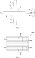
- the aircraft component 20 may alternatively be configured as or otherwise included as part of an airframe 30 of the aircraft.
- the aircraft component 20, for example, may be (or may be part of) an aircraft wing 32, an aircraft fuselage skin 34, an aircraft stabilizer 36, or the like.
- the aircraft component 20 may still alternatively be configured as or otherwise included as part of a structure within the aircraft airframe 30; e.g., within a cabin of the aircraft.
- the present disclosure is not limited to manufacturing the foregoing exemplary aircraft components.
- the methods of the present disclosure may be utilized for manufacturing (e.g., repairing or creating) non-aircraft components.
- the thermoplastic component is generally described below as the aircraft component 20.
- the aircraft component 20 includes a plurality of thermoplastic bodies consolidated (e.g., induction welded) together to form the aircraft component 20.
- the first thermoplastic body may be a thermoplastic component base 38 and the second thermoplastic body may be a thermoplastic component patch 40.
- the component base 38 may be a portion or an entirety of a damaged aircraft component which is to be repaired (prior to the consolidation).
- the component patch 40 may be configured to partially or completely repair damage to the damaged aircraft component (prior to the consolidation).
- thermoplastic bodies 38 and 40 may be discrete layers of thermoplastic material which are consolidated together to form a consolidated multilayer patch, which patch may then be bonded to a damaged aircraft component in a subsequent operation.
- each of the thermoplastic bodies 38 and 40 may be a discrete layer of thermoplastic material (prior to the consolidation)
- the first thermoplastic body may be a preform of the aircraft component 20 to which additional thermoplastic material (e.g., at least or only the second thermoplastic body 40) is consolidated with, etc.
- additional thermoplastic material e.g., at least or only the second thermoplastic body 40
- the first thermoplastic body and the second thermoplastic body may be generally described below as the component base 38 and the component patch 40.
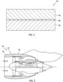
- each of the thermoplastic bodies 38 and 40 may include a thermoplastic matrix 42 and fiber-reinforcement 44 embedded within the thermoplastic matrix 42.
- the thermoplastic matrix 42 may include a semi-crystalline thermoplastic material and/or an amorphous thermoplastic material.
- the fiber-reinforcement 44 may include a plurality of fibers 46 such as, but not limited to, carbon fibers (e.g., fibers of carbon fiber material).
- the fiber-reinforcement 44 and its fibers 46 may be arranged in one or more layers 48 within the respective thermoplastic body 38, 40 and its thermoplastic matrix 42.
- the fibers 46 in each layer 48 of the fiber-reinforcement 44 may be arranged in a unidirectional pattern.
- the fibers 46 in one or more of the layers 48 of the fiber-reinforcement 44 may be arranged in a multi-directional pattern; e.g., woven together in a weave.
- the fibers 46 in each layer 48 of the fiber-reinforcement 44 include continuous fibers and/or chopped fibers.
- the present disclosure is not limited to the foregoing exemplary fiber types and/or fiber arrangements.
- each thermoplastic body 38, 40 is described above as including the fiber-reinforcement 44 embedded within the thermoplastic matrix 42, it is contemplated one of the thermoplastic bodies 38 and 40 (e.g., the component patch 40) may alternatively be configured without any the fiber-reinforcement 44 embedded within the thermoplastic matrix 42.
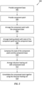
- FIG. 5 is a flow diagram of a method 500 for manufacturing a thermoplastic component; e.g., a thermoplastic composite component.
- this manufacturing method 500 is described below as a repair method and with respect to the repaired aircraft component 20 described above.
- the present disclosure is not limited thereto.
- the manufacturing method 500 may alternatively be performed to create a brand new aircraft component.
- the manufacturing method 500 may be performed to repair or create components with various other structural configurations than that described above.
- the component base 38 (the first thermoplastic body) is provided.
- the damaged component to be repaired may be removed from the aircraft and/or otherwise received and prepared for patching. Alternatively, the damaged component to be repaired may be prepared for patching while still installed with or otherwise onboard the aircraft.
- the component patch 40 (the second thermoplastic body) is provided.
- a piece of thermoplastic stock material may be cutout to form the component patch 40.
- the thermoplastic stock material may be a (e.g., laminated) sheet of thermoplastic composite material, prepreg material, etc.
- the component patch 40 may alternatively be laminated, molded, pressed, injection molded, stamped and/or otherwise formed.
- the component patch 40 is arranged with the component base 38 for consolidation; e.g., induction welding together.
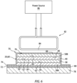
- the component patch 40 of FIG. 6 is disposed on the component base 38.
- the component base 38 of FIG. 6 has a base thickness that extends vertically between and to a first (e.g., lower) surface 50 of the component base 38 and a second (e.g., upper) surface 52 of the component base 38.
- the component patch 40 of FIG. 6 has a patch thickness that extends vertically between and to a first (e.g., lower) surface 54 of the component patch 40 and a second (e.g., upper) surface 56 of the component patch 40.
- the patch first surface 54 of FIG. 6 is abutted against and contacts the base second surface 52.
- the patch first surface 54 for example, may lay against (e.g., rest on, be disposed in full contact with, be disposed flat against, etc.) the base second surface 52.
- the surfaces 52 and 54 are shown with straight-line sectional geometries in the plane of FIG. 6 , it is contemplated the surfaces 52 and 54 may alternatively have non-straight-line (e.g., curved, compound, etc.) sectional geometries in the plane of FIG. 6 . Moreover, the surfaces 52 and 54 may also or alternatively have straight-line or non-straight-line sectional geometries in a plane perpendicular to the plane of FIG. 6 .
- the surfaces 52 and 54 may be flat, planar surfaces, two-dimensional (2D) curved or otherwise non-flat surfaces, or three-dimensional (3D) curved or otherwise non-flat surfaces.
- one or more conduction heating plates 58A and 58B are arranged with a stack 60 of the thermoplastic bodies 38 and 40.
- Each heating plate 58 may be constructed from a magnetic material such as stainless steel (SS).
- the first (e.g., lower) heating plate 58A has a plate thickness that extends vertically between and to a first (e.g., lower) surface 62 of the first heating plate 58A and a second (e.g., upper) surface 64 of the first heating plate 58A.
- the first plate second surface 64 is abutted against and engages (e.g., contacts) the stack 60 at a first (e.g., lower) side of the stack 60.
- the first heating plate 58A is abutted against the component base 38.
- the first plate second surface 64 may lay against (e.g., rest on, be disposed in full contact with, be disposed flat against, etc.) the base first surface 50.
- the second (e.g., upper) heating plate 58B has a plate thickness that extends vertically between and to a first (e.g., lower) surface 66 of the second heating plate 58B and a second (e.g., upper) surface 68 of the second heating plate 58B.
- the second plate first surface 66 is abutted against and engages (e.g., contacts) the stack 60 at a second (e.g., upper) side of the stack 60.
- the second heating plate 58B is abutted against the component patch 40 (and the component base 38 in some embodiments; e.g., see FIG. 7 ).
- the second plate first surface 66 may lay against (e.g., rest on, be disposed in full contact with, be disposed flat against, etc.) the patch second surface 56 (and the base second surface 52 in some embodiments; e.g., see FIG. 7 ). With this arrangement, the stack 60 is located (e.g., sandwiched) vertically between the first heating plate 58A and the second heating plate 58B.
- the surfaces 50 and 64, 56 and 66 are shown with straight-line sectional geometries in the plane of FIG. 6 , it is contemplated the surfaces 50 and 64, 56 and 66 may alternatively have non-straight-line (e.g., curved, compound, etc.) sectional geometries in the plane of FIG. 6 . Moreover, the surfaces 50 and 64, 56 and 66 may also or alternatively have straight-line or non-straight-line sectional geometries in a plane perpendicular to the plane of FIG. 6 .
- the surfaces 50 and 64, 56 and 66 may be flat, planar surfaces, two-dimensional (2D) curved or otherwise non-flat surfaces, or three-dimensional (3D) curved or otherwise non-flat surfaces.
- each surface 50, 56, 64, 66 may be an uninterrupted surface.
- the term "uninterrupted” may describe a surface without any discrete apertures (e.g., channels, dimples, notches, grooves, etc.) and/or without any discrete protrusions (e.g., ribs, bumps, etc.)
- the present disclosure is not limited to such an uninterrupted surface arrangement.
- one or more of the heating plates 58 may each be coated with a protective coating.
- One or more of the heating plate surfaces 64 and/or 66 of FIG. 6 may be coated with the protective coating.
- This protective coating may be selected to facilitate release of the thermoplastic bodies 38 and 40 from the heating plates 58 following consolidation.
- the protective coating may be constructed from Frekote ® material manufactured by Henkel Adhesive Technologies of Düsseldorf, Germany.
- the stack 60 is compressed.
- the stack 60 and the heating plates 58 of FIG. 6 may be configured within a vacuum bag 70.
- This vacuum bag 70 may be formed by a first (e.g., lower) sheet 72 and a second (e.g., upper) sheet 74.
- Each vacuum bag sheet 72, 74 may be constructed from a material which does not (e.g., permanently) bond with the heating plates 58 during the manufacturing method 500.
- the material may be a polyimide such as Kapton ® polyimide material manufactured by DowDuPont Company (formerly DuPont de Nemours, Inc. of Delaware, United States).
- the component base 38 is pressed between the first heating plate 58A and the component patch 40, and the component patch 40 is pressed between the second heating plate 58B and the component base 38.
- various other techniques are known in the art for applying pressure to (e.g., compressing) a stack of thermoplastic material for consolidation, and the present disclosure is not limited to any particular ones thereof.
- the vacuum bagged (or otherwise compressed) arrangement of the thermoplastic bodies 38 and 40 and the heating plates 58 may be supported on a rigid support structure 78; e.g., a processing table.
- the vacuum bagged arrangement of FIG. 6 for example, is disposed on a protective layer 80 (e.g., a silicon sheet), which protective layer 80 is disposed on the support structure 78.
- a protective layer 80 e.g., a silicon sheet
- the vacuum bagged arrangement may alternatively be disposed directly on the support structure 78 without the protective layer 80 in other embodiments.
- an induction heating coil 82 (e.g., an induction welding coil) is arranged with the (e.g., compressed) stack 60.
- the induction heating coil 82 may be disposed over and slightly spaced from) the vacuum bagged arrangement.
- the second heating plate 58B is positioned vertically between the stack 60 and the induction heating coil 82, and the arrangement of the stack 60 and the heating plates 58 is arranged vertically between the support structure 78 and the induction heating coil 82.
- the induction heating coil 82 may include one or more coil segments 84, where each coil segment 84 may be arranged to be substantially parallel with at least some or all of the fibers 46 (schematically shown) within one or more of the thermoplastic bodies 38 and 40.
- thermoplastic bodies 38 and 40 of FIG. 6 are consolidated together while being compressed at a consolidation pressure; e.g., via the vacuum bag 70.
- This consolidation is performed using (e.g., only) the induction heating coil 82; e.g., without any other heating devices such as other electric heater(s), an oven, an autoclave, etc.
- a power source 86 coupled to the induction heating coil 82 may provide a high frequency (e.g., alternating) current to the induction heating coil 82.
- the induction heating coil 82 may subsequently generate electromagnetic waves which concurrently excite (a) at least some (or all) of the fibers 46 (see FIGS.
- the fibers 46 and heating plate material are excited by eddy currents propagated within the respective elements 38, 40, 58A and/or 58B.
- the excitation of the fibers 46 may elevate a temperature of each thermoplastic body 38, 40.
- the excitation of the heating plate material may elevate a temperature of each heating plate 58.
- Each heated heating plate 58 may subsequently further elevate the temperature of each thermoplastic body 38, 40 by conducting heat energy into the respective thermoplastic body 38, 40.
- the thermoplastic bodies 38 and 40 are heated to a melting point temperature of its thermoplastic matrix 42 (see FIG.
- thermoplastic matrix 42 of each thermoplastic body 38, 40 melts.
- a melt layer 88 (see FIG. 1 ) may form at an interface between the thermoplastic bodies 38 and 40. This melt layer 88 may bond the thermoplastic bodies 38 and 40 together upon cooling thereof.
- the thermoplastic bodies 38 and 40 may be consolidated together using relatively low power from the power source 86 as compared to, for example, power required for a typical autoclave, oven or hot stamp press.
- the stack 60 may be compressed during the consolidation at a relatively low consolidation pressure.
- the consolidation pressure may be equal to or less than two atmospheric pressure (2 atm, 203 kPa) during the consolidation.
- the consolidation pressure may be maintained at about (e.g., +/- 0.1 atm, +/- 10 kPa) or exactly one atmospheric pressure (1 atm, 101kPa).
- other thermoplastic welding techniques may require pressures greater than three atmospheric pressure (3 atm, 304 kPa).
- thermoplastic bodies 38 and 40 are removed from the vacuum bag 70.
- the heating plates 58 are removed as well to provide the aircraft component 20; e.g., the repaired aircraft component.
- the aircraft component 20 of FIG. 6 includes the single component patch 40, it is contemplated the aircraft component 20 may alternatively include multiple component patches 40A-E (generally referred to as "40") as shown in FIGS. 9-11 ; e.g., a multi-layered patch / patch structure.
- the multiple component patches 40 may be consolidated with the component base 38 simultaneously using the consolidation step 514 (e.g., induction welding) described above.
- each component patch 40 (or sets of some of the component patches 40) may alternatively be discretely consolidated with the component base 38 where the multi-layered patch / patch structure, for example, is relatively thick.
- the one or more component patches 40 may be configured to cover a damaged portion 90 of the component base 38.
- the one or more component patches 40 may be configured to at least partially or completely replace the damaged portion of the component base 38.
- some or all of the damaged portion of the component base 38 may be removed from the component base 38 via one or more removal techniques; e.g., machining, milling, cutting, grit blasting, etc. This removal may form an aperture 92 (e.g., a tapered aperture, a plateaued aperture, etc.) in the component base 38.
- the component 11 projects (e.g., partially) vertically into the component base 38 from an exterior surface (e.g., 52) of the component base 38 to an interior surface 94 of the component base 38. Following this removal, the one or more of the component patches 40 disposed with (e.g., in, along and/or over) the aperture 92 and subsequently consolidated with the component base 38 as described above.
Landscapes
- Engineering & Computer Science (AREA)
- Mechanical Engineering (AREA)
- Manufacturing & Machinery (AREA)
- Transportation (AREA)
- Aviation & Aerospace Engineering (AREA)
- Textile Engineering (AREA)
- Physics & Mathematics (AREA)
- Thermal Sciences (AREA)
Abstract
Description
- This disclosure relates generally to joining methods and, more particularly, to consolidating thermoplastic material together.
- Various systems and methods are known in the art for joining thermoplastic materials together. While these known joining systems and methods have various benefits, there is still room in the art for improvement.
- According to an aspect of the present disclosure, a repair method is provided during which a thermoplastic patch is arranged on a thermoplastic aircraft component. The thermoplastic patch and the thermoplastic aircraft component each include a thermoplastic matrix and a plurality of fibers embedded within the thermoplastic matrix. A metal plate is arranged against a stack. The stack includes the thermoplastic patch and the thermoplastic aircraft component. The thermoplastic patch and the thermoplastic aircraft component are consolidated together. The consolidating includes concurrently induction heating the thermoplastic patch, the thermoplastic aircraft component and the metal plate using an induction heating coil.
- According to another aspect of the present disclosure, which the Applicant expressly reserves the right to claim independently, a method is provided during which a first thermoplastic body is arranged on a second thermoplastic body. The first thermoplastic body and the second thermoplastic body each include a thermoplastic matrix and a plurality of fibers embedded within the thermoplastic matrix. A stack is arranged between a first magnetic plate and a second magnetic plate. The stack includes the first thermoplastic body and the second thermoplastic body. The stack is pressed between the first magnetic plate and the second magnetic plate. At least the first thermoplastic body and the second thermoplastic body are consolidated together to form a thermoplastic component. The consolidating includes induction heating the first thermoplastic body, the second thermoplastic body, the first magnetic plate and the second magnetic plate using an induction heating coil.
- According to still another aspect of the present disclosure, which the Applicant expressly reserves the right to claim independently, another method is provided during which a first thermoplastic body is arranged on a second thermoplastic body. The first thermoplastic body and the second thermoplastic body each include a thermoplastic matrix and a plurality of fibers embedded within the thermoplastic matrix. A magnetic plate is arranged against a stack which includes the first thermoplastic body and the second thermoplastic body. The first thermoplastic body is pressed against the second thermoplastic body at a pressure less than two atmospheric pressure. The first thermoplastic body, the second thermoplastic body and the magnetic plate are induction heated to consolidate at least the first thermoplastic body and the second thermoplastic body together to form a thermoplastic component for an aircraft.
- The first magnetic plate may have a first uninterrupted surface engaging the stack. The second magnetic plate may also or alternatively have a second uninterrupted surface engaging the stack.
- The method may also include configuring the stack, the first magnetic plate and the second magnetic plate within a vacuum bag. The stack may be pressed between the first magnetic plate and the second magnetic plate using the vacuum bag.
- The induction heating may include exciting at least some of the fibers in the thermoplastic patch, at least some of the fibers in the thermoplastic aircraft component and at least some material of the metal plate with eddy currents generated by the induction heating coil.
- The metal plate may be induction heated to provide a heated metal plate. The consolidating may also include conduction heating the stack with heat energy from the heated metal plate.
- The metal plate may be arranged against the thermoplastic patch.
- The method may also include arranging a second metal plate against the thermoplastic aircraft component. The stack may be located between the metal plate and the second metal plate. The consolidating may include concurrently induction heating the thermoplastic patch, the thermoplastic aircraft component, the metal plate and the second metal plate using the induction heating coil.
- The method may also include pressing the stack between the metal plate and the second metal plate during the consolidating.
- The method may also include pressing the thermoplastic patch between the metal plate and the thermoplastic aircraft component during the consolidating.
- The metal plate may be arranged against the thermoplastic aircraft component.
- The method may also include pressing the thermoplastic aircraft component between the metal plate and the thermoplastic patch during the consolidating.
- The method may also include pressing the thermoplastic patch against the thermoplastic aircraft component at a pressure less than two atmospheric pressure.
- A surface of the metal plate contacting the stack may be covered with a protective material.
- The aircraft component may be configured with an aircraft during the consolidating.
- The method may also include supporting the stack on a support structure during the consolidating with a protective layer between the stack and the support structure.
- The fibers may include a plurality of carbon fibers.
- The fibers in at least one layer of the thermoplastic patch may be unidirectional. In addition or alternatively, the fibers in at least one layer of the thermoplastic aircraft component may be unidirectional, at least along the thermoplastic patch.
- The thermoplastic patch may include a plurality of unconsolidated patch layers prior to the consolidating.
- The present disclosure may include any one or more of the individual features disclosed above and/or below alone or in any combination thereof.
- The foregoing features and the operation of the invention will become more apparent in light of the following description and the accompanying drawings.
-
-
FIG. 1 is a partial schematic sectional illustration of a thermoplastic component. -
FIG. 2 is a cutaway schematic sectional illustration of an aircraft propulsion system which may include the thermoplastic component. -
FIG. 3 is a schematic illustration of an aircraft with an aircraft airframe which may include the thermoplastic component. -
FIG. 4 is a partial schematic sectional illustration of layers in the thermoplastic component. -
FIG. 5 is a flow diagram of a method for manufacturing a thermoplastic component. -
FIG. 6 is a partial schematic sectional illustration of a system for consolidating a stack of thermoplastic components together using an induction heating coil. -
FIG. 7 is a partial schematic sectional illustration of a portion of the consolidation system with another stack of thermoplastic components. -
FIG. 8 is a schematic plan view illustration of the induction heating coil along one of the thermoplastic components. -
FIG. 9 is a partial schematic sectional illustration of a portion of the consolidation system with still another stack of thermoplastic components. -
FIGS. 10 and 11 are partial schematic sectional illustrations of alternative thermoplastic component configurations. - The present disclosure includes methods and systems for manufacturing a thermoplastic component 20 (e.g., a thermoplastic composite component) of an aircraft, where an exemplary section of the
aircraft component 20 is shown inFIG. 1 . The aircraft may be an airplane, a helicopter, a drone (e.g., an unmanned aerial vehicle (UAV)) or any other manned or unmanned aerial vehicle or system. - The term "manufacturing" may describe a process for original manufacturing the
aircraft component 20; e.g., creating a brand new aircraft component. The term "manufacturing" may also or alternatively describe a process for remanufacturing or otherwise repairing theaircraft component 20; e.g., restoring one or more features of a previously formed aircraft component to brand new condition, similar to brand new condition, better than brand new condition, etc. Theaircraft component 20, for example, may be repaired to fix one or more defects (e.g., cracks, wear and/or other damage) imparted during previous use of the aircraft component. Theaircraft component 20 may also or alternatively be repaired to fix one or more defects imparted during the initial formation of the aircraft component. For ease of description, however, theaircraft component 20 may be described below as a repaired aircraft component, and the methods may be described as repair methods. - Referring to
FIG. 2 , theaircraft component 20 may be configured as or otherwise included as part of anacelle 22 of apropulsion system 24 for the aircraft. Theaircraft component 20, for example, may be (or may be part of) a component of anacelle inlet structure 26; e.g., a nacelle inlet lip (e.g., a nose lip), a nacelle outer barrel, a nacelle inner barrel, etc. In another example, theaircraft component 20 may be (or may be part of) another component of thepropulsion system nacelle 22 such as a cowl 28 (e.g., a fan cowl), or the like. Referring toFIG. 3 , theaircraft component 20 may alternatively be configured as or otherwise included as part of anairframe 30 of the aircraft. Theaircraft component 20, for example, may be (or may be part of) anaircraft wing 32, anaircraft fuselage skin 34, anaircraft stabilizer 36, or the like. Theaircraft component 20 may still alternatively be configured as or otherwise included as part of a structure within theaircraft airframe 30; e.g., within a cabin of the aircraft. The present disclosure, however, is not limited to manufacturing the foregoing exemplary aircraft components. Moreover, it is contemplated the methods of the present disclosure may be utilized for manufacturing (e.g., repairing or creating) non-aircraft components. However, for ease of description, the thermoplastic component is generally described below as theaircraft component 20. - Referring again to
FIG. 1 , theaircraft component 20 includes a plurality of thermoplastic bodies consolidated (e.g., induction welded) together to form theaircraft component 20. Where theaircraft component 20 is a repaired aircraft component, the first thermoplastic body may be athermoplastic component base 38 and the second thermoplastic body may be athermoplastic component patch 40. Thecomponent base 38 may be a portion or an entirety of a damaged aircraft component which is to be repaired (prior to the consolidation). Thecomponent patch 40 may be configured to partially or completely repair damage to the damaged aircraft component (prior to the consolidation). Alternatively, thethermoplastic bodies aircraft component 20 is a brand new aircraft component, each of thethermoplastic bodies aircraft component 20 to which additional thermoplastic material (e.g., at least or only the second thermoplastic body 40) is consolidated with, etc. However, for ease of description, the first thermoplastic body and the second thermoplastic body may be generally described below as thecomponent base 38 and thecomponent patch 40. - Referring to
FIG. 4 , each of thethermoplastic bodies thermoplastic matrix 42 and fiber-reinforcement 44 embedded within thethermoplastic matrix 42. Thethermoplastic matrix 42 may include a semi-crystalline thermoplastic material and/or an amorphous thermoplastic material. The fiber-reinforcement 44 may include a plurality offibers 46 such as, but not limited to, carbon fibers (e.g., fibers of carbon fiber material). The fiber-reinforcement 44 and itsfibers 46 may be arranged in one ormore layers 48 within the respectivethermoplastic body thermoplastic matrix 42. Thefibers 46 in eachlayer 48 of the fiber-reinforcement 44 may be arranged in a unidirectional pattern. Alternatively, thefibers 46 in one or more of thelayers 48 of the fiber-reinforcement 44 may be arranged in a multi-directional pattern; e.g., woven together in a weave. Thefibers 46 in eachlayer 48 of the fiber-reinforcement 44 include continuous fibers and/or chopped fibers. The present disclosure, however, is not limited to the foregoing exemplary fiber types and/or fiber arrangements. Moreover, while eachthermoplastic body thermoplastic matrix 42, it is contemplated one of thethermoplastic bodies 38 and 40 (e.g., the component patch 40) may alternatively be configured without any the fiber-reinforcement 44 embedded within thethermoplastic matrix 42. -
FIG. 5 is a flow diagram of amethod 500 for manufacturing a thermoplastic component; e.g., a thermoplastic composite component. For ease of description, thismanufacturing method 500 is described below as a repair method and with respect to the repairedaircraft component 20 described above. The present disclosure, however, is not limited thereto. Themanufacturing method 500, for example, may alternatively be performed to create a brand new aircraft component. Moreover, themanufacturing method 500 may be performed to repair or create components with various other structural configurations than that described above. - In
step 502, the component base 38 (the first thermoplastic body) is provided. The damaged component to be repaired, for example, may be removed from the aircraft and/or otherwise received and prepared for patching. Alternatively, the damaged component to be repaired may be prepared for patching while still installed with or otherwise onboard the aircraft. - In
step 504, the component patch 40 (the second thermoplastic body) is provided. A piece of thermoplastic stock material, for example, may be cutout to form thecomponent patch 40. The thermoplastic stock material may be a (e.g., laminated) sheet of thermoplastic composite material, prepreg material, etc. Thecomponent patch 40, of course, may alternatively be laminated, molded, pressed, injection molded, stamped and/or otherwise formed. - In
step 506, thecomponent patch 40 is arranged with thecomponent base 38 for consolidation; e.g., induction welding together. For example, thecomponent patch 40 ofFIG. 6 is disposed on thecomponent base 38. Thecomponent base 38 ofFIG. 6 has a base thickness that extends vertically between and to a first (e.g., lower)surface 50 of thecomponent base 38 and a second (e.g., upper) surface 52 of thecomponent base 38. Thecomponent patch 40 ofFIG. 6 has a patch thickness that extends vertically between and to a first (e.g., lower)surface 54 of thecomponent patch 40 and a second (e.g., upper) surface 56 of thecomponent patch 40. The patchfirst surface 54 ofFIG. 6 is abutted against and contacts the basesecond surface 52. The patchfirst surface 54, for example, may lay against (e.g., rest on, be disposed in full contact with, be disposed flat against, etc.) the basesecond surface 52. - While the
surfaces FIG. 6 , it is contemplated thesurfaces FIG. 6 . Moreover, thesurfaces FIG. 6 . For example, thesurfaces - In
step 508, one or moreconduction heating plates thermoplastic bodies heating plate 58A has a plate thickness that extends vertically between and to a first (e.g., lower)surface 62 of thefirst heating plate 58A and a second (e.g., upper) surface 64 of thefirst heating plate 58A. The first platesecond surface 64 is abutted against and engages (e.g., contacts) the stack 60 at a first (e.g., lower) side of the stack 60. Thefirst heating plate 58A, for example, is abutted against thecomponent base 38. The first platesecond surface 64, for example, may lay against (e.g., rest on, be disposed in full contact with, be disposed flat against, etc.) the basefirst surface 50. Similarly, the second (e.g., upper)heating plate 58B has a plate thickness that extends vertically between and to a first (e.g., lower)surface 66 of thesecond heating plate 58B and a second (e.g., upper) surface 68 of thesecond heating plate 58B. The second platefirst surface 66 is abutted against and engages (e.g., contacts) the stack 60 at a second (e.g., upper) side of the stack 60. Thesecond heating plate 58B, for example, is abutted against the component patch 40 (and thecomponent base 38 in some embodiments; e.g., seeFIG. 7 ). The second platefirst surface 66, for example, may lay against (e.g., rest on, be disposed in full contact with, be disposed flat against, etc.) the patch second surface 56 (and the basesecond surface 52 in some embodiments; e.g., seeFIG. 7 ). With this arrangement, the stack 60 is located (e.g., sandwiched) vertically between thefirst heating plate 58A and thesecond heating plate 58B. - While the
surfaces FIG. 6 , it is contemplated thesurfaces FIG. 6 . Moreover, thesurfaces FIG. 6 . For example, thesurfaces surface - In some embodiments, one or more of the heating plates 58 may each be coated with a protective coating. One or more of the heating plate surfaces 64 and/or 66 of
FIG. 6 , for example, may be coated with the protective coating. This protective coating may be selected to facilitate release of thethermoplastic bodies - In
step 510, the stack 60 is compressed. The stack 60 and the heating plates 58 ofFIG. 6 , for example, may be configured within avacuum bag 70. Thisvacuum bag 70 may be formed by a first (e.g., lower)sheet 72 and a second (e.g., upper)sheet 74. Eachvacuum bag sheet manufacturing method 500. For example, the material may be a polyimide such as Kapton® polyimide material manufactured by DowDuPont Company (formerly DuPont de Nemours, Inc. of Delaware, United States). Thesecond sheet 74 ofFIG. 6 is attached to thefirst sheet 72 at (e.g., on, adjacent or proximate) an outer periphery of thesecond sheet 74 to form an internal volume 76 (e.g., a vacuum bag cavity) between thefirst sheet 72 and thesecond sheet 74. The stack 60 and the heating plates 58 are disposed within thisinternal volume 76, and a vacuum is applied to thevacuum bag 70 to compress the stack 60 vertically between the heating plates 58. More particularly, thecomponent base 38 is pressed between thefirst heating plate 58A and thecomponent patch 40, and thecomponent patch 40 is pressed between thesecond heating plate 58B and thecomponent base 38. Of course, various other techniques are known in the art for applying pressure to (e.g., compressing) a stack of thermoplastic material for consolidation, and the present disclosure is not limited to any particular ones thereof. - The vacuum bagged (or otherwise compressed) arrangement of the
thermoplastic bodies rigid support structure 78; e.g., a processing table. The vacuum bagged arrangement ofFIG. 6 , for example, is disposed on a protective layer 80 (e.g., a silicon sheet), whichprotective layer 80 is disposed on thesupport structure 78. Of course, it is contemplated the vacuum bagged arrangement may alternatively be disposed directly on thesupport structure 78 without theprotective layer 80 in other embodiments. - In
step 512, an induction heating coil 82 (e.g., an induction welding coil) is arranged with the (e.g., compressed) stack 60. Theinduction heating coil 82, for example, may be disposed over and slightly spaced from) the vacuum bagged arrangement. Here, thesecond heating plate 58B is positioned vertically between the stack 60 and theinduction heating coil 82, and the arrangement of the stack 60 and the heating plates 58 is arranged vertically between thesupport structure 78 and theinduction heating coil 82. Referring toFIG. 8 , theinduction heating coil 82 may include one ormore coil segments 84, where eachcoil segment 84 may be arranged to be substantially parallel with at least some or all of the fibers 46 (schematically shown) within one or more of thethermoplastic bodies - In
step 514, thethermoplastic bodies FIG. 6 are consolidated together while being compressed at a consolidation pressure; e.g., via thevacuum bag 70. This consolidation is performed using (e.g., only) theinduction heating coil 82; e.g., without any other heating devices such as other electric heater(s), an oven, an autoclave, etc. Apower source 86 coupled to theinduction heating coil 82, for example, may provide a high frequency (e.g., alternating) current to theinduction heating coil 82. Theinduction heating coil 82 may subsequently generate electromagnetic waves which concurrently excite (a) at least some (or all) of the fibers 46 (seeFIGS. 4 and8 ) within each thermoplasticcomposite body fibers 46 and heating plate material are excited by eddy currents propagated within therespective elements fibers 46 may elevate a temperature of eachthermoplastic body thermoplastic body thermoplastic body thermoplastic bodies FIG. 4 ) such that thethermoplastic matrix 42 of eachthermoplastic body FIG. 1 ) may form at an interface between thethermoplastic bodies melt layer 88 may bond thethermoplastic bodies thermoplastic bodies thermoplastic bodies thermoplastic bodies power source 86 as compared to, for example, power required for a typical autoclave, oven or hot stamp press. - Using the foregoing
consolidation step 514, the stack 60 may be compressed during the consolidation at a relatively low consolidation pressure. The consolidation pressure, for example, may be equal to or less than two atmospheric pressure (2 atm, 203 kPa) during the consolidation. For example, the consolidation pressure may be maintained at about (e.g., +/- 0.1 atm, +/- 10 kPa) or exactly one atmospheric pressure (1 atm, 101kPa). By contrast, other thermoplastic welding techniques may require pressures greater than three atmospheric pressure (3 atm, 304 kPa). - Following the consolidation, the now consolidated
thermoplastic bodies vacuum bag 70. The heating plates 58 are removed as well to provide theaircraft component 20; e.g., the repaired aircraft component. - While the
aircraft component 20 ofFIG. 6 includes thesingle component patch 40, it is contemplated theaircraft component 20 may alternatively includemultiple component patches 40A-E (generally referred to as "40") as shown inFIGS. 9-11 ; e.g., a multi-layered patch / patch structure. Here, themultiple component patches 40 may be consolidated with thecomponent base 38 simultaneously using the consolidation step 514 (e.g., induction welding) described above. Of course, in other embodiments, it is contemplated each component patch 40 (or sets of some of the component patches 40) may alternatively be discretely consolidated with thecomponent base 38 where the multi-layered patch / patch structure, for example, is relatively thick. - In some embodiments, referring to
FIG. 10 , the one ormore component patches 40 may be configured to cover a damagedportion 90 of thecomponent base 38. In other embodiments, referring toFIG. 11 , the one ormore component patches 40 may be configured to at least partially or completely replace the damaged portion of thecomponent base 38. For example, some or all of the damaged portion of thecomponent base 38 may be removed from thecomponent base 38 via one or more removal techniques; e.g., machining, milling, cutting, grit blasting, etc. This removal may form an aperture 92 (e.g., a tapered aperture, a plateaued aperture, etc.) in thecomponent base 38. Theaperture 92 ofFIG. 11 projects (e.g., partially) vertically into thecomponent base 38 from an exterior surface (e.g., 52) of thecomponent base 38 to aninterior surface 94 of thecomponent base 38. Following this removal, the one or more of thecomponent patches 40 disposed with (e.g., in, along and/or over) theaperture 92 and subsequently consolidated with thecomponent base 38 as described above. - While various embodiments of the present invention have been disclosed, it will be apparent to those of ordinary skill in the art that many more embodiments and implementations are possible within the scope of the invention. For example, the present invention as described herein includes several aspects and embodiments that include particular features. Although these features may be described individually, it is within the scope of the present invention that some or all of these features may be combined with any one of the aspects and remain within the scope of the invention. Accordingly, the present invention is not to be restricted except in light of the attached claims and their equivalents.
Claims (15)
- A repair method, comprising:arranging a thermoplastic patch (40) on a thermoplastic aircraft component (38), the thermoplastic patch (40) and the thermoplastic aircraft component (38) each including a thermoplastic matrix (42) and a plurality of fibers (46) embedded within the thermoplastic matrix (42);arranging a metal plate (58A; 58B) against a stack (60), the stack (60) including the thermoplastic patch (40) and the thermoplastic aircraft component (38); andconsolidating the thermoplastic patch (40) and the thermoplastic aircraft component (38) together, the consolidating comprising concurrently induction heating the thermoplastic patch (40), the thermoplastic aircraft component (38) and the metal plate (58A; 58B) using an induction heating coil (82).
- The repair method of claim 1, wherein the induction heating comprises exciting at least some of the plurality of fibers (46) in the thermoplastic patch (40), at least some of the plurality of fibers (46) in the thermoplastic aircraft component (38) and at least some material of the metal plate (58A; 58B) with eddy currents generated by the induction heating coil (82).
- The repair method of claim 1 or 2, whereinthe metal plate (58A; 58B) is induction heated to provide a heated metal plate (58A; 58B); andthe consolidating further comprises conduction heating the stack (60) with heat energy from the heated metal plate (58A; 58B).
- The repair method of any preceding claim, wherein the metal plate (58B) is arranged against the thermoplastic patch (40).
- The repair method of claim 4, further comprising:arranging a second metal plate (58A) against the thermoplastic aircraft component (38), the stack (60) located between the metal plate (58B) and the second metal plate (58A);the consolidating comprising concurrently induction heating the thermoplastic patch (40), the thermoplastic aircraft component (38), the metal plate (58B) and the second metal plate (58A) using the induction heating coil (82),wherein optionally, the method further comprises pressing the stack (60) between the metal plate (58B) and the second metal plate (58A) during the consolidating.
- The repair method of claim 5, further comprising:
configuring the stack (60), the metal plate (58B) and the second metal plate (58A) within a vacuum bag (70), the stack (60) pressed between the metal plate (58B) and the second metal plate (58A) using the vacuum bag (70). - The repair method of claim 5 or 6, wherein at least one ofthe metal plate (58B) comprises a first uninterrupted surface (66) engaging the stack (60); orthe second metal plate (58A) comprises a second uninterrupted surface (64) engaging the stack (60).
- The repair method of any preceding claim, further comprising pressing the thermoplastic patch (40) between the metal plate (58B) and the thermoplastic aircraft component (38) during the consolidating.
- The repair method of any preceding claim, wherein the metal plate (58A; 58B) is arranged against the thermoplastic aircraft component (38).
- The repair method of any preceding claim, further comprising:pressing the thermoplastic aircraft component (38) between the metal plate (58A) and the thermoplastic patch (40) during the consolidating; and/orpressing the thermoplastic patch (40) against the thermoplastic aircraft component (38) at a pressure less than two atmospheric pressure (203 kPa).
- The repair method of any preceding claim, wherein a surface (64; 66) of the metal plate (58A; 58B) contacting the stack (60) is covered with a protective material.
- The repair method of any preceding claim, wherein the aircraft component (20; 38) is configured with an aircraft during the consolidating.
- The repair method of any preceding claim, further comprising supporting the stack (60) on a support structure (78) during the consolidating with a protective layer (80) between the stack (60) and the support structure (78).
- The repair method of any preceding claim, wherein at least one of:the plurality of fibers (46) comprise a plurality of carbon fibers;the plurality of fibers (46) in at least one layer (48) of the thermoplastic patch (40) are unidirectional; orthe plurality of fibers (46) in at least one layer (48) of the thermoplastic aircraft component (38) are unidirectional, at least along the thermoplastic patch (40).
- The repair method of any preceding claim, wherein the thermoplastic patch (40) includes a plurality of unconsolidated patch layers (48) prior to the consolidating.
Applications Claiming Priority (1)
| Application Number | Priority Date | Filing Date | Title |
|---|---|---|---|
| US18/228,358 US20250042578A1 (en) | 2023-07-31 | 2023-07-31 | Consolidating thermoplastic material with induction heating coil and heating plate(s) |
Publications (2)
| Publication Number | Publication Date |
|---|---|
| EP4501597A1 true EP4501597A1 (en) | 2025-02-05 |
| EP4501597B1 EP4501597B1 (en) | 2026-05-13 |
Family
ID=91375310
Family Applications (1)
| Application Number | Title | Priority Date | Filing Date |
|---|---|---|---|
| EP24179384.3A Active EP4501597B1 (en) | 2023-07-31 | 2024-05-31 | Consolidating thermoplastic material with induction heating coil and heating plate(s) |
Country Status (2)
| Country | Link |
|---|---|
| US (1) | US20250042578A1 (en) |
| EP (1) | EP4501597B1 (en) |
Citations (2)
| Publication number | Priority date | Publication date | Assignee | Title |
|---|---|---|---|---|
| DE102011076463A1 (en) * | 2011-05-25 | 2012-11-29 | Deutsches Zentrum für Luft- und Raumfahrt e.V. | Repair method for molding of plastic material e.g. fiber-reinforced plastics during aircraft manufacture, involves generating heat and subjecting to alternating magnetic field to apply plastic repair element to molded portion damaged area |
| US20220161508A1 (en) * | 2018-10-04 | 2022-05-26 | Premium Aerotec Gmbh | Methods For Producing A Structural Component |
Family Cites Families (5)
| Publication number | Priority date | Publication date | Assignee | Title |
|---|---|---|---|---|
| FR3017562B1 (en) * | 2014-02-18 | 2016-03-11 | Airbus Operations Sas | METHOD AND DEVICE FOR INDUCTION WELDING OF PARTS IN COMPOSITE MATERIALS. |
| US10589477B2 (en) * | 2016-05-02 | 2020-03-17 | GM Global Technology Operations LLC | Cosmetic repair of a thermoplastic carbon fiber composite |
| FR3123239B1 (en) * | 2021-05-25 | 2023-06-30 | Inst De Rech Tech Jules Verne | Dynamic induction welding installation |
| US20230211567A1 (en) * | 2021-12-30 | 2023-07-06 | Rohr, Inc. | Resistance repair of thermoplastic components |
| US12263652B2 (en) * | 2022-01-02 | 2025-04-01 | Rohr, Inc. | Heat shield with coil recess for induction welding |
-
2023
- 2023-07-31 US US18/228,358 patent/US20250042578A1/en active Pending
-
2024
- 2024-05-31 EP EP24179384.3A patent/EP4501597B1/en active Active
Patent Citations (2)
| Publication number | Priority date | Publication date | Assignee | Title |
|---|---|---|---|---|
| DE102011076463A1 (en) * | 2011-05-25 | 2012-11-29 | Deutsches Zentrum für Luft- und Raumfahrt e.V. | Repair method for molding of plastic material e.g. fiber-reinforced plastics during aircraft manufacture, involves generating heat and subjecting to alternating magnetic field to apply plastic repair element to molded portion damaged area |
| US20220161508A1 (en) * | 2018-10-04 | 2022-05-26 | Premium Aerotec Gmbh | Methods For Producing A Structural Component |
Also Published As
| Publication number | Publication date |
|---|---|
| EP4501597B1 (en) | 2026-05-13 |
| US20250042578A1 (en) | 2025-02-06 |
Similar Documents
| Publication | Publication Date | Title |
|---|---|---|
| CN111716758B (en) | Co-consolidation tools and related methods | |
| US9889603B2 (en) | Method for local reinforcement of a composite fiber reinforced panel and panel obtained using said method | |
| US5832594A (en) | Tooling for inserting Z-pins | |
| US9359060B2 (en) | Laminated composite radius filler with geometric shaped filler element and method of forming the same | |
| EP3498465B1 (en) | Induction heating cell with cauls over mandrels and method of using it | |
| KR20150065669A (en) | Composite structure having a stabilizing element | |
| JP2012532760A (en) | Curing system and method utilizing electromagnetic force and conduction heat transfer | |
| JP2022540837A (en) | Aircraft fuselage structure and manufacturing method thereof | |
| US12565014B2 (en) | Methods for producing a structural component | |
| EP3392027B1 (en) | Systems and methods for assembling elongate composite structures | |
| CN118107195A (en) | Curing tool | |
| EP4501597B1 (en) | Consolidating thermoplastic material with induction heating coil and heating plate(s) | |
| JP2021104666A (en) | Method and apparatus for fabricating composite fuselage structure | |
| EP4289609B1 (en) | Heating thermoplastic material using electric heater(s) for thermal anti-icing system | |
| US20230398752A1 (en) | Curing thermoset material using electric heater(s) for thermal anti-icing system | |
| US20260014762A1 (en) | Repairing composite thermoplastic component using induction / conductive heating | |
| US12485623B2 (en) | Induction welding thermoplastic material with different electrical conductivities | |
| US12220876B2 (en) | Method for surface structuring | |
| US20260054458A1 (en) | Structure repair using ferromagnetic induction heating and thermoplastic adhesive | |
| US20210170699A1 (en) | Composite material forming method and composite material | |
| US20260048561A1 (en) | Repair delamination in thermoplastic component with horizontal ultrasonic welding | |
| US20240239061A1 (en) | Method of Manufacturing a Component from a Composite Material with Locally Different Thicknesses | |
| EP4631701A1 (en) | Continuous ultrasonic welding thermoplastic material for aerospace component repair | |
| US20250367892A1 (en) | Forming aircraft component with lightning strike protection | |
| US20250033302A1 (en) | Horizontal ultrasonic welding thermoplastic material |
Legal Events
| Date | Code | Title | Description |
|---|---|---|---|
| PUAI | Public reference made under article 153(3) epc to a published international application that has entered the european phase |
Free format text: ORIGINAL CODE: 0009012 |
|
| STAA | Information on the status of an ep patent application or granted ep patent |
Free format text: STATUS: THE APPLICATION HAS BEEN PUBLISHED |
|
| AK | Designated contracting states |
Kind code of ref document: A1 Designated state(s): AL AT BE BG CH CY CZ DE DK EE ES FI FR GB GR HR HU IE IS IT LI LT LU LV MC ME MK MT NL NO PL PT RO RS SE SI SK SM TR |
|
| STAA | Information on the status of an ep patent application or granted ep patent |
Free format text: STATUS: REQUEST FOR EXAMINATION WAS MADE |
|
| 17P | Request for examination filed |
Effective date: 20250804 |
|
| GRAJ | Information related to disapproval of communication of intention to grant by the applicant or resumption of examination proceedings by the epo deleted |
Free format text: ORIGINAL CODE: EPIDOSDIGR1 |
|
| GRAP | Despatch of communication of intention to grant a patent |
Free format text: ORIGINAL CODE: EPIDOSNIGR1 |
|
| GRAP | Despatch of communication of intention to grant a patent |
Free format text: ORIGINAL CODE: EPIDOSNIGR1 |
|
| STAA | Information on the status of an ep patent application or granted ep patent |
Free format text: STATUS: GRANT OF PATENT IS INTENDED |
|
| RIC1 | Information provided on ipc code assigned before grant |
Ipc: B29C 65/18 20060101AFI20251114BHEP Ipc: B29C 65/32 20060101ALI20251114BHEP Ipc: B29C 65/36 20060101ALI20251114BHEP Ipc: B29C 65/72 20060101ALI20251114BHEP Ipc: B29C 73/12 20060101ALI20251114BHEP Ipc: B29C 73/32 20060101ALI20251114BHEP Ipc: B29C 73/10 20060101ALI20251114BHEP Ipc: B29C 73/30 20060101ALI20251114BHEP Ipc: B29C 73/34 20060101ALI20251114BHEP Ipc: B29L 31/30 20060101ALN20251114BHEP Ipc: B29C 35/08 20060101ALN20251114BHEP |
|
| RIC1 | Information provided on ipc code assigned before grant |
Ipc: B29C 65/18 20060101AFI20251205BHEP Ipc: B29C 65/32 20060101ALI20251205BHEP Ipc: B29C 65/36 20060101ALI20251205BHEP Ipc: B29C 65/72 20060101ALI20251205BHEP Ipc: B29C 73/12 20060101ALI20251205BHEP Ipc: B29C 73/32 20060101ALI20251205BHEP Ipc: B29C 73/10 20060101ALI20251205BHEP Ipc: B29C 73/30 20060101ALI20251205BHEP Ipc: B29C 73/34 20060101ALI20251205BHEP Ipc: B29L 31/30 20060101ALN20251205BHEP Ipc: B29C 35/08 20060101ALN20251205BHEP |
|
| INTG | Intention to grant announced |
Effective date: 20251223 |
|
| GRAS | Grant fee paid |
Free format text: ORIGINAL CODE: EPIDOSNIGR3 |
|
| GRAA | (expected) grant |
Free format text: ORIGINAL CODE: 0009210 |
|
| STAA | Information on the status of an ep patent application or granted ep patent |
Free format text: STATUS: THE PATENT HAS BEEN GRANTED |
|
| AK | Designated contracting states |
Kind code of ref document: B1 Designated state(s): AL AT BE BG CH CY CZ DE DK EE ES FI FR GB GR HR HU IE IS IT LI LT LU LV MC ME MK MT NL NO PL PT RO RS SE SI SK SM TR |
|
| REG | Reference to a national code |
Ref country code: CH Ref legal event code: F10 Free format text: ST27 STATUS EVENT CODE: U-0-0-F10-F00 (AS PROVIDED BY THE NATIONAL OFFICE) Effective date: 20260513 |