EP4501592A1 - Pouch-type battery cell sealing device comprising pair of sealing rollers, sealing method using same, and pouch-type battery cell manufactured using same - Google Patents
Pouch-type battery cell sealing device comprising pair of sealing rollers, sealing method using same, and pouch-type battery cell manufactured using same Download PDFInfo
- Publication number
- EP4501592A1 EP4501592A1 EP23892021.9A EP23892021A EP4501592A1 EP 4501592 A1 EP4501592 A1 EP 4501592A1 EP 23892021 A EP23892021 A EP 23892021A EP 4501592 A1 EP4501592 A1 EP 4501592A1
- Authority
- EP
- European Patent Office
- Prior art keywords
- sealing
- pouch
- battery cell
- shaped battery
- sealed portion
- Prior art date
- Legal status (The legal status is an assumption and is not a legal conclusion. Google has not performed a legal analysis and makes no representation as to the accuracy of the status listed.)
- Granted
Links
Images

Classifications
-
- H—ELECTRICITY
- H01—ELECTRIC ELEMENTS
- H01M—PROCESSES OR MEANS, e.g. BATTERIES, FOR THE DIRECT CONVERSION OF CHEMICAL ENERGY INTO ELECTRICAL ENERGY
- H01M50/00—Constructional details or processes of manufacture of the non-active parts of electrochemical cells other than fuel cells, e.g. hybrid cells
- H01M50/10—Primary casings; Jackets or wrappings
- H01M50/102—Primary casings; Jackets or wrappings characterised by their shape or physical structure
- H01M50/105—Pouches or flexible bags
-
- B—PERFORMING OPERATIONS; TRANSPORTING
- B29—WORKING OF PLASTICS; WORKING OF SUBSTANCES IN A PLASTIC STATE IN GENERAL
- B29C—SHAPING OR JOINING OF PLASTICS; SHAPING OF MATERIAL IN A PLASTIC STATE, NOT OTHERWISE PROVIDED FOR; AFTER-TREATMENT OF THE SHAPED PRODUCTS, e.g. REPAIRING
- B29C66/00—General aspects of processes or apparatus for joining preformed parts
- B29C66/40—General aspects of joining substantially flat articles, e.g. plates, sheets or web-like materials; Making flat seams in tubular or hollow articles; Joining single elements to substantially flat surfaces
- B29C66/41—Joining substantially flat articles ; Making flat seams in tubular or hollow articles
- B29C66/43—Joining a relatively small portion of the surface of said articles
- B29C66/433—Casing-in, i.e. enclosing an element between two sheets by an outlined seam
-
- B—PERFORMING OPERATIONS; TRANSPORTING
- B29—WORKING OF PLASTICS; WORKING OF SUBSTANCES IN A PLASTIC STATE IN GENERAL
- B29C—SHAPING OR JOINING OF PLASTICS; SHAPING OF MATERIAL IN A PLASTIC STATE, NOT OTHERWISE PROVIDED FOR; AFTER-TREATMENT OF THE SHAPED PRODUCTS, e.g. REPAIRING
- B29C65/00—Joining or sealing of preformed parts, e.g. welding of plastics materials; Apparatus therefor
- B29C65/02—Joining or sealing of preformed parts, e.g. welding of plastics materials; Apparatus therefor by heating, with or without pressure
-
- B—PERFORMING OPERATIONS; TRANSPORTING
- B29—WORKING OF PLASTICS; WORKING OF SUBSTANCES IN A PLASTIC STATE IN GENERAL
- B29C—SHAPING OR JOINING OF PLASTICS; SHAPING OF MATERIAL IN A PLASTIC STATE, NOT OTHERWISE PROVIDED FOR; AFTER-TREATMENT OF THE SHAPED PRODUCTS, e.g. REPAIRING
- B29C65/00—Joining or sealing of preformed parts, e.g. welding of plastics materials; Apparatus therefor
- B29C65/02—Joining or sealing of preformed parts, e.g. welding of plastics materials; Apparatus therefor by heating, with or without pressure
- B29C65/18—Joining or sealing of preformed parts, e.g. welding of plastics materials; Apparatus therefor by heating, with or without pressure using heated tools
-
- B—PERFORMING OPERATIONS; TRANSPORTING
- B29—WORKING OF PLASTICS; WORKING OF SUBSTANCES IN A PLASTIC STATE IN GENERAL
- B29C—SHAPING OR JOINING OF PLASTICS; SHAPING OF MATERIAL IN A PLASTIC STATE, NOT OTHERWISE PROVIDED FOR; AFTER-TREATMENT OF THE SHAPED PRODUCTS, e.g. REPAIRING
- B29C66/00—General aspects of processes or apparatus for joining preformed parts
- B29C66/01—General aspects dealing with the joint area or with the area to be joined
- B29C66/05—Particular design of joint configurations
- B29C66/10—Particular design of joint configurations particular design of the joint cross-sections
- B29C66/11—Joint cross-sections comprising a single joint-segment, i.e. one of the parts to be joined comprising a single joint-segment in the joint cross-section
- B29C66/112—Single lapped joints
-
- B—PERFORMING OPERATIONS; TRANSPORTING
- B29—WORKING OF PLASTICS; WORKING OF SUBSTANCES IN A PLASTIC STATE IN GENERAL
- B29C—SHAPING OR JOINING OF PLASTICS; SHAPING OF MATERIAL IN A PLASTIC STATE, NOT OTHERWISE PROVIDED FOR; AFTER-TREATMENT OF THE SHAPED PRODUCTS, e.g. REPAIRING
- B29C66/00—General aspects of processes or apparatus for joining preformed parts
- B29C66/01—General aspects dealing with the joint area or with the area to be joined
- B29C66/05—Particular design of joint configurations
- B29C66/10—Particular design of joint configurations particular design of the joint cross-sections
- B29C66/13—Single flanged joints; Fin-type joints; Single hem joints; Edge joints; Interpenetrating fingered joints; Other specific particular designs of joint cross-sections not provided for in groups B29C66/11 - B29C66/12
- B29C66/131—Single flanged joints, i.e. one of the parts to be joined being rigid and flanged in the joint area
-
- B—PERFORMING OPERATIONS; TRANSPORTING
- B29—WORKING OF PLASTICS; WORKING OF SUBSTANCES IN A PLASTIC STATE IN GENERAL
- B29C—SHAPING OR JOINING OF PLASTICS; SHAPING OF MATERIAL IN A PLASTIC STATE, NOT OTHERWISE PROVIDED FOR; AFTER-TREATMENT OF THE SHAPED PRODUCTS, e.g. REPAIRING
- B29C66/00—General aspects of processes or apparatus for joining preformed parts
- B29C66/01—General aspects dealing with the joint area or with the area to be joined
- B29C66/32—Measures for keeping the burr form under control; Avoiding burr formation; Shaping the burr
- B29C66/326—Shaping the burr, e.g. by the joining tool
-
- B—PERFORMING OPERATIONS; TRANSPORTING
- B29—WORKING OF PLASTICS; WORKING OF SUBSTANCES IN A PLASTIC STATE IN GENERAL
- B29C—SHAPING OR JOINING OF PLASTICS; SHAPING OF MATERIAL IN A PLASTIC STATE, NOT OTHERWISE PROVIDED FOR; AFTER-TREATMENT OF THE SHAPED PRODUCTS, e.g. REPAIRING
- B29C66/00—General aspects of processes or apparatus for joining preformed parts
- B29C66/50—General aspects of joining tubular articles; General aspects of joining long products, i.e. bars or profiled elements; General aspects of joining single elements to tubular articles, hollow articles or bars; General aspects of joining several hollow-preforms to form hollow or tubular articles
- B29C66/51—Joining tubular articles, profiled elements or bars; Joining single elements to tubular articles, hollow articles or bars; Joining several hollow-preforms to form hollow or tubular articles
- B29C66/53—Joining single elements to tubular articles, hollow articles or bars
- B29C66/534—Joining single elements to open ends of tubular or hollow articles or to the ends of bars
- B29C66/5346—Joining single elements to open ends of tubular or hollow articles or to the ends of bars said single elements being substantially flat
- B29C66/53461—Joining single elements to open ends of tubular or hollow articles or to the ends of bars said single elements being substantially flat joining substantially flat covers and/or substantially flat bottoms to open ends of container bodies
-
- B—PERFORMING OPERATIONS; TRANSPORTING
- B29—WORKING OF PLASTICS; WORKING OF SUBSTANCES IN A PLASTIC STATE IN GENERAL
- B29C—SHAPING OR JOINING OF PLASTICS; SHAPING OF MATERIAL IN A PLASTIC STATE, NOT OTHERWISE PROVIDED FOR; AFTER-TREATMENT OF THE SHAPED PRODUCTS, e.g. REPAIRING
- B29C66/00—General aspects of processes or apparatus for joining preformed parts
- B29C66/70—General aspects of processes or apparatus for joining preformed parts characterised by the composition, physical properties or the structure of the material of the parts to be joined; Joining with non-plastics material
- B29C66/72—General aspects of processes or apparatus for joining preformed parts characterised by the composition, physical properties or the structure of the material of the parts to be joined; Joining with non-plastics material characterised by the structure of the material of the parts to be joined
- B29C66/723—General aspects of processes or apparatus for joining preformed parts characterised by the composition, physical properties or the structure of the material of the parts to be joined; Joining with non-plastics material characterised by the structure of the material of the parts to be joined being multi-layered
- B29C66/7232—General aspects of processes or apparatus for joining preformed parts characterised by the composition, physical properties or the structure of the material of the parts to be joined; Joining with non-plastics material characterised by the structure of the material of the parts to be joined being multi-layered comprising a non-plastics layer
- B29C66/72321—General aspects of processes or apparatus for joining preformed parts characterised by the composition, physical properties or the structure of the material of the parts to be joined; Joining with non-plastics material characterised by the structure of the material of the parts to be joined being multi-layered comprising a non-plastics layer consisting of metals or their alloys
-
- B—PERFORMING OPERATIONS; TRANSPORTING
- B29—WORKING OF PLASTICS; WORKING OF SUBSTANCES IN A PLASTIC STATE IN GENERAL
- B29C—SHAPING OR JOINING OF PLASTICS; SHAPING OF MATERIAL IN A PLASTIC STATE, NOT OTHERWISE PROVIDED FOR; AFTER-TREATMENT OF THE SHAPED PRODUCTS, e.g. REPAIRING
- B29C66/00—General aspects of processes or apparatus for joining preformed parts
- B29C66/70—General aspects of processes or apparatus for joining preformed parts characterised by the composition, physical properties or the structure of the material of the parts to be joined; Joining with non-plastics material
- B29C66/73—General aspects of processes or apparatus for joining preformed parts characterised by the composition, physical properties or the structure of the material of the parts to be joined; Joining with non-plastics material characterised by the intensive physical properties of the material of the parts to be joined, by the optical properties of the material of the parts to be joined, by the extensive physical properties of the parts to be joined, by the state of the material of the parts to be joined or by the material of the parts to be joined being a thermoplastic or a thermoset
- B29C66/739—General aspects of processes or apparatus for joining preformed parts characterised by the composition, physical properties or the structure of the material of the parts to be joined; Joining with non-plastics material characterised by the intensive physical properties of the material of the parts to be joined, by the optical properties of the material of the parts to be joined, by the extensive physical properties of the parts to be joined, by the state of the material of the parts to be joined or by the material of the parts to be joined being a thermoplastic or a thermoset characterised by the material of the parts to be joined being a thermoplastic or a thermoset
- B29C66/7392—General aspects of processes or apparatus for joining preformed parts characterised by the composition, physical properties or the structure of the material of the parts to be joined; Joining with non-plastics material characterised by the intensive physical properties of the material of the parts to be joined, by the optical properties of the material of the parts to be joined, by the extensive physical properties of the parts to be joined, by the state of the material of the parts to be joined or by the material of the parts to be joined being a thermoplastic or a thermoset characterised by the material of the parts to be joined being a thermoplastic or a thermoset characterised by the material of at least one of the parts being a thermoplastic
- B29C66/73921—General aspects of processes or apparatus for joining preformed parts characterised by the composition, physical properties or the structure of the material of the parts to be joined; Joining with non-plastics material characterised by the intensive physical properties of the material of the parts to be joined, by the optical properties of the material of the parts to be joined, by the extensive physical properties of the parts to be joined, by the state of the material of the parts to be joined or by the material of the parts to be joined being a thermoplastic or a thermoset characterised by the material of the parts to be joined being a thermoplastic or a thermoset characterised by the material of at least one of the parts being a thermoplastic characterised by the materials of both parts being thermoplastics
-
- B—PERFORMING OPERATIONS; TRANSPORTING
- B29—WORKING OF PLASTICS; WORKING OF SUBSTANCES IN A PLASTIC STATE IN GENERAL
- B29C—SHAPING OR JOINING OF PLASTICS; SHAPING OF MATERIAL IN A PLASTIC STATE, NOT OTHERWISE PROVIDED FOR; AFTER-TREATMENT OF THE SHAPED PRODUCTS, e.g. REPAIRING
- B29C66/00—General aspects of processes or apparatus for joining preformed parts
- B29C66/80—General aspects of machine operations or constructions and parts thereof
- B29C66/81—General aspects of the pressing elements, i.e. the elements applying pressure on the parts to be joined in the area to be joined, e.g. the welding jaws or clamps
- B29C66/814—General aspects of the pressing elements, i.e. the elements applying pressure on the parts to be joined in the area to be joined, e.g. the welding jaws or clamps characterised by the design of the pressing elements, e.g. of the welding jaws or clamps
- B29C66/8145—General aspects of the pressing elements, i.e. the elements applying pressure on the parts to be joined in the area to be joined, e.g. the welding jaws or clamps characterised by the design of the pressing elements, e.g. of the welding jaws or clamps characterised by the constructional aspects of the pressing elements, e.g. of the welding jaws or clamps
- B29C66/81463—General aspects of the pressing elements, i.e. the elements applying pressure on the parts to be joined in the area to be joined, e.g. the welding jaws or clamps characterised by the design of the pressing elements, e.g. of the welding jaws or clamps characterised by the constructional aspects of the pressing elements, e.g. of the welding jaws or clamps comprising a plurality of single pressing elements, e.g. a plurality of sonotrodes, or comprising a plurality of single counter-pressing elements, e.g. a plurality of anvils, said plurality of said single elements being suitable for making a single joint
-
- B—PERFORMING OPERATIONS; TRANSPORTING
- B29—WORKING OF PLASTICS; WORKING OF SUBSTANCES IN A PLASTIC STATE IN GENERAL
- B29C—SHAPING OR JOINING OF PLASTICS; SHAPING OF MATERIAL IN A PLASTIC STATE, NOT OTHERWISE PROVIDED FOR; AFTER-TREATMENT OF THE SHAPED PRODUCTS, e.g. REPAIRING
- B29C66/00—General aspects of processes or apparatus for joining preformed parts
- B29C66/80—General aspects of machine operations or constructions and parts thereof
- B29C66/83—General aspects of machine operations or constructions and parts thereof characterised by the movement of the joining or pressing tools
- B29C66/834—General aspects of machine operations or constructions and parts thereof characterised by the movement of the joining or pressing tools moving with the parts to be joined
- B29C66/8341—Roller, cylinder or drum types; Band or belt types; Ball types
- B29C66/83411—Roller, cylinder or drum types
- B29C66/83413—Roller, cylinder or drum types cooperating rollers, cylinders or drums
-
- B—PERFORMING OPERATIONS; TRANSPORTING
- B29—WORKING OF PLASTICS; WORKING OF SUBSTANCES IN A PLASTIC STATE IN GENERAL
- B29C—SHAPING OR JOINING OF PLASTICS; SHAPING OF MATERIAL IN A PLASTIC STATE, NOT OTHERWISE PROVIDED FOR; AFTER-TREATMENT OF THE SHAPED PRODUCTS, e.g. REPAIRING
- B29C66/00—General aspects of processes or apparatus for joining preformed parts
- B29C66/80—General aspects of machine operations or constructions and parts thereof
- B29C66/83—General aspects of machine operations or constructions and parts thereof characterised by the movement of the joining or pressing tools
- B29C66/836—Moving relative to and tangentially to the parts to be joined, e.g. transversely to the displacement of the parts to be joined, e.g. using a X-Y table
- B29C66/8362—Rollers, cylinders or drums moving relative to and tangentially to the parts to be joined
-
- B—PERFORMING OPERATIONS; TRANSPORTING
- B29—WORKING OF PLASTICS; WORKING OF SUBSTANCES IN A PLASTIC STATE IN GENERAL
- B29C—SHAPING OR JOINING OF PLASTICS; SHAPING OF MATERIAL IN A PLASTIC STATE, NOT OTHERWISE PROVIDED FOR; AFTER-TREATMENT OF THE SHAPED PRODUCTS, e.g. REPAIRING
- B29C66/00—General aspects of processes or apparatus for joining preformed parts
- B29C66/90—Measuring or controlling the joining process
- B29C66/91—Measuring or controlling the joining process by measuring or controlling the temperature, the heat or the thermal flux
- B29C66/914—Measuring or controlling the joining process by measuring or controlling the temperature, the heat or the thermal flux by controlling or regulating the temperature, the heat or the thermal flux
- B29C66/9141—Measuring or controlling the joining process by measuring or controlling the temperature, the heat or the thermal flux by controlling or regulating the temperature, the heat or the thermal flux by controlling or regulating the temperature
- B29C66/91421—Measuring or controlling the joining process by measuring or controlling the temperature, the heat or the thermal flux by controlling or regulating the temperature, the heat or the thermal flux by controlling or regulating the temperature of the joining tools
-
- B—PERFORMING OPERATIONS; TRANSPORTING
- B29—WORKING OF PLASTICS; WORKING OF SUBSTANCES IN A PLASTIC STATE IN GENERAL
- B29C—SHAPING OR JOINING OF PLASTICS; SHAPING OF MATERIAL IN A PLASTIC STATE, NOT OTHERWISE PROVIDED FOR; AFTER-TREATMENT OF THE SHAPED PRODUCTS, e.g. REPAIRING
- B29C66/00—General aspects of processes or apparatus for joining preformed parts
- B29C66/90—Measuring or controlling the joining process
- B29C66/91—Measuring or controlling the joining process by measuring or controlling the temperature, the heat or the thermal flux
- B29C66/919—Measuring or controlling the joining process by measuring or controlling the temperature, the heat or the thermal flux characterised by specific temperature, heat or thermal flux values or ranges
-
- H—ELECTRICITY
- H01—ELECTRIC ELEMENTS
- H01M—PROCESSES OR MEANS, e.g. BATTERIES, FOR THE DIRECT CONVERSION OF CHEMICAL ENERGY INTO ELECTRICAL ENERGY
- H01M10/00—Secondary cells; Manufacture thereof
- H01M10/04—Construction or manufacture in general
- H01M10/0404—Machines for assembling batteries
-
- H—ELECTRICITY
- H01—ELECTRIC ELEMENTS
- H01M—PROCESSES OR MEANS, e.g. BATTERIES, FOR THE DIRECT CONVERSION OF CHEMICAL ENERGY INTO ELECTRICAL ENERGY
- H01M50/00—Constructional details or processes of manufacture of the non-active parts of electrochemical cells other than fuel cells, e.g. hybrid cells
- H01M50/10—Primary casings; Jackets or wrappings
- H01M50/116—Primary casings; Jackets or wrappings characterised by the material
- H01M50/117—Inorganic material
- H01M50/119—Metals
-
- H—ELECTRICITY
- H01—ELECTRIC ELEMENTS
- H01M—PROCESSES OR MEANS, e.g. BATTERIES, FOR THE DIRECT CONVERSION OF CHEMICAL ENERGY INTO ELECTRICAL ENERGY
- H01M50/00—Constructional details or processes of manufacture of the non-active parts of electrochemical cells other than fuel cells, e.g. hybrid cells
- H01M50/10—Primary casings; Jackets or wrappings
- H01M50/116—Primary casings; Jackets or wrappings characterised by the material
- H01M50/121—Organic material
-
- H—ELECTRICITY
- H01—ELECTRIC ELEMENTS
- H01M—PROCESSES OR MEANS, e.g. BATTERIES, FOR THE DIRECT CONVERSION OF CHEMICAL ENERGY INTO ELECTRICAL ENERGY
- H01M50/00—Constructional details or processes of manufacture of the non-active parts of electrochemical cells other than fuel cells, e.g. hybrid cells
- H01M50/10—Primary casings; Jackets or wrappings
- H01M50/116—Primary casings; Jackets or wrappings characterised by the material
- H01M50/124—Primary casings; Jackets or wrappings characterised by the material having a layered structure
-
- H—ELECTRICITY
- H01—ELECTRIC ELEMENTS
- H01M—PROCESSES OR MEANS, e.g. BATTERIES, FOR THE DIRECT CONVERSION OF CHEMICAL ENERGY INTO ELECTRICAL ENERGY
- H01M50/00—Constructional details or processes of manufacture of the non-active parts of electrochemical cells other than fuel cells, e.g. hybrid cells
- H01M50/10—Primary casings; Jackets or wrappings
- H01M50/183—Sealing members
-
- H—ELECTRICITY
- H01—ELECTRIC ELEMENTS
- H01M—PROCESSES OR MEANS, e.g. BATTERIES, FOR THE DIRECT CONVERSION OF CHEMICAL ENERGY INTO ELECTRICAL ENERGY
- H01M50/00—Constructional details or processes of manufacture of the non-active parts of electrochemical cells other than fuel cells, e.g. hybrid cells
- H01M50/10—Primary casings; Jackets or wrappings
- H01M50/183—Sealing members
- H01M50/186—Sealing members characterised by the disposition of the sealing members
-
- B—PERFORMING OPERATIONS; TRANSPORTING
- B29—WORKING OF PLASTICS; WORKING OF SUBSTANCES IN A PLASTIC STATE IN GENERAL
- B29C—SHAPING OR JOINING OF PLASTICS; SHAPING OF MATERIAL IN A PLASTIC STATE, NOT OTHERWISE PROVIDED FOR; AFTER-TREATMENT OF THE SHAPED PRODUCTS, e.g. REPAIRING
- B29C66/00—General aspects of processes or apparatus for joining preformed parts
- B29C66/70—General aspects of processes or apparatus for joining preformed parts characterised by the composition, physical properties or the structure of the material of the parts to be joined; Joining with non-plastics material
- B29C66/71—General aspects of processes or apparatus for joining preformed parts characterised by the composition, physical properties or the structure of the material of the parts to be joined; Joining with non-plastics material characterised by the composition of the plastics material of the parts to be joined
-
- B—PERFORMING OPERATIONS; TRANSPORTING
- B29—WORKING OF PLASTICS; WORKING OF SUBSTANCES IN A PLASTIC STATE IN GENERAL
- B29C—SHAPING OR JOINING OF PLASTICS; SHAPING OF MATERIAL IN A PLASTIC STATE, NOT OTHERWISE PROVIDED FOR; AFTER-TREATMENT OF THE SHAPED PRODUCTS, e.g. REPAIRING
- B29C66/00—General aspects of processes or apparatus for joining preformed parts
- B29C66/80—General aspects of machine operations or constructions and parts thereof
- B29C66/83—General aspects of machine operations or constructions and parts thereof characterised by the movement of the joining or pressing tools
- B29C66/832—Reciprocating joining or pressing tools
- B29C66/8322—Joining or pressing tools reciprocating along one axis
- B29C66/83221—Joining or pressing tools reciprocating along one axis cooperating reciprocating tools, each tool reciprocating along one axis
-
- B—PERFORMING OPERATIONS; TRANSPORTING
- B29—WORKING OF PLASTICS; WORKING OF SUBSTANCES IN A PLASTIC STATE IN GENERAL
- B29K—INDEXING SCHEME ASSOCIATED WITH SUBCLASSES B29B, B29C OR B29D, RELATING TO MOULDING MATERIALS OR TO MATERIALS FOR MOULDS, REINFORCEMENTS, FILLERS OR PREFORMED PARTS, e.g. INSERTS
- B29K2705/00—Use of metals, their alloys or their compounds, for preformed parts, e.g. for inserts
- B29K2705/02—Aluminium
-
- B—PERFORMING OPERATIONS; TRANSPORTING
- B29—WORKING OF PLASTICS; WORKING OF SUBSTANCES IN A PLASTIC STATE IN GENERAL
- B29L—INDEXING SCHEME ASSOCIATED WITH SUBCLASS B29C, RELATING TO PARTICULAR ARTICLES
- B29L2031/00—Other particular articles
- B29L2031/34—Electrical apparatus, e.g. sparking plugs or parts thereof
- B29L2031/3468—Batteries, accumulators or fuel cells
-
- B—PERFORMING OPERATIONS; TRANSPORTING
- B29—WORKING OF PLASTICS; WORKING OF SUBSTANCES IN A PLASTIC STATE IN GENERAL
- B29L—INDEXING SCHEME ASSOCIATED WITH SUBCLASS B29C, RELATING TO PARTICULAR ARTICLES
- B29L2031/00—Other particular articles
- B29L2031/712—Containers; Packaging elements or accessories, Packages
- B29L2031/7146—Battery-cases
-
- Y—GENERAL TAGGING OF NEW TECHNOLOGICAL DEVELOPMENTS; GENERAL TAGGING OF CROSS-SECTIONAL TECHNOLOGIES SPANNING OVER SEVERAL SECTIONS OF THE IPC; TECHNICAL SUBJECTS COVERED BY FORMER USPC CROSS-REFERENCE ART COLLECTIONS [XRACs] AND DIGESTS
- Y02—TECHNOLOGIES OR APPLICATIONS FOR MITIGATION OR ADAPTATION AGAINST CLIMATE CHANGE
- Y02E—REDUCTION OF GREENHOUSE GAS [GHG] EMISSIONS, RELATED TO ENERGY GENERATION, TRANSMISSION OR DISTRIBUTION
- Y02E60/00—Enabling technologies; Technologies with a potential or indirect contribution to GHG emissions mitigation
- Y02E60/10—Energy storage using batteries
-
- Y—GENERAL TAGGING OF NEW TECHNOLOGICAL DEVELOPMENTS; GENERAL TAGGING OF CROSS-SECTIONAL TECHNOLOGIES SPANNING OVER SEVERAL SECTIONS OF THE IPC; TECHNICAL SUBJECTS COVERED BY FORMER USPC CROSS-REFERENCE ART COLLECTIONS [XRACs] AND DIGESTS
- Y02—TECHNOLOGIES OR APPLICATIONS FOR MITIGATION OR ADAPTATION AGAINST CLIMATE CHANGE
- Y02P—CLIMATE CHANGE MITIGATION TECHNOLOGIES IN THE PRODUCTION OR PROCESSING OF GOODS
- Y02P70/00—Climate change mitigation technologies in the production process for final industrial or consumer products
- Y02P70/50—Manufacturing or production processes characterised by the final manufactured product
Definitions
- the present invention relates to a pouch-shaped battery cell sealing apparatus including a pair of sealing rollers, a sealing method using the same, and a pouch-shaped battery cell manufactured using the same. More particularly, the present invention relates to a pouch-shaped battery cell sealing apparatus including a pair of sealing rollers capable of rapidly discharging gas when the internal pressure of a pouch-shaped battery cell increases, thereby preventing explosion of the pouch-shaped battery cell, a sealing method using the same, and a pouch-shaped battery cell manufactured using the same.
- a lithium secondary battery which is capable of being charged and discharged, has been widely used as an energy source for wireless mobile devices or wearable devices, which are worn on bodies, and has also been used as an energy source for electric vehicles and hybrid electric vehicles presented as alternatives to existing gasoline and diesel vehicles, which cause air pollution.
- the lithium secondary battery may be classified as a prismatic battery cell including a metal can-shaped case, a cylindrical battery cell including a metal can-shaped case, or a pouch-shaped battery cell including a case formed of a laminate sheet.
- the pouch-shaped battery cell is most commonly used due to easy deformation and an increase in energy density when stored and stacked.
- the battery case In the lithium secondary battery, a side reaction occurs between the surface of an electrode and an electrolytic solution during repeated charging and discharging, and if gas generated at this time is not discharged from the battery case, the battery case may swell or may be deformed.
- the pouch-shaped battery cell includes no separate venting structure, unlike the cylindrical battery cell, which includes a safety vent, venting may occur at a part of a thermally fused outer periphery at which gas is concentrated or adhesion due to thermal fusion is low.
- the pouch-shaped battery cell is manufactured by shaping a laminated sheet including an outer resin layer, a metal layer, and an inner adhesive layer into a pouch-shaped battery case, receiving an electrode assembly in the pouch-shaped battery case, and sealing the pouch-shaped battery case.
- the laminate sheet may have a more complex and varied layered structure depending on implementation of the laminate sheet and the environment to which the laminate sheet is applied.
- an outer periphery of the pouch-shaped battery case is pressed using a heating block configured to provide heat and pressure.
- the inner adhesive layer is melted, whereby inner adhesive layers of an upper case and a lower case, which are stacked on top of each other, are thermally fused to form a seal.
- FIG. 1 is a front view of a conventional pouch-shaped battery cell and an apparatus for sealing the same.
- a pouch-shaped battery case includes an upper case 110 and a lower case 120. Outer peripheries of the upper case 110 and the lower case 120 are disposed between a pair of sealing tools 10, and then pressed and heated with the pair of sealing tools 10 to form a sealed portion.
- Each of the upper case 110 and the lower case 120 is made of a laminate sheet in which an outer resin layer, a metal layer, and an inner adhesive layer are sequentially laminated, and the inner adhesive layer of the upper case 110 and the inner adhesive layer of the lower case 120 are melted.
- the pair of sealing tools 10 is configured to press the entire area of the sealed portion at once, and the size of the inner polyball 101 is formed so as to be greater than the size of the outer polyball 102 since there is a lot of movement of the inner adhesive layer in an inward direction where a wide empty space is formed in a direction toward an electrode assembly receiving portion.
- the inner polyball 101 has a larger size, as described above, venting of the pouch-shaped battery case is difficult even though the internal pressure of the pouch-shaped battery cell increases, whereby the pressure in the pouch-shaped battery case gradually increases.
- the pouch-shaped battery cell may explode.
- Patent Document 1 relates to a battery cell including a battery case made of a laminate sheet having a structure in which a first resin layer, a metal layer, and a second resin layer are sequentially laminated, wherein the laminate sheet includes a first sheet portion and a second sheet portion facing each other to form a surplus sealed portion, and at least a part of the surplus sealed portion includes a resin layer fusion portion formed by the first resin layer of the first sheet portion and the first resin layer of the second sheet portion and a metal layer weld portion formed by an end of the metal layer of the first sheet portion and an end of the metal layer of the second sheet portion.
- Patent Document 1 a first sealing tool and a second sealing tool with a semicircular shape convex in directions toward the first sheet portion and the second sheet portion are used, in a sealed portion formed by the first sealing tool and the second sealing tool, a resin layer fusion portion is formed inside the sealed portion adjacent to an electrode assembly, whereby sealing force of the battery cell is increased.
- Patent Document 1 Korean Patent Application Publication No. 2016-0073097 (2016.06.24)
- the present invention has been made in view of the above problems, and it is an object of the present invention to provide a pouch-shaped battery cell sealing apparatus capable of reducing the thickness of an inner adhesive layer of a sealed portion of a pouch-shaped battery cell such that venting can easily occur by reducing a venting pressure in the sealed portion, a sealing method using the same, and a pouch-shaped battery cell manufactured using the same.
- a pouch-shaped battery cell sealing apparatus to accomplish the above object includes a pair of sealing rollers configured to press and roll an upper part and a lower part of a sealed portion of a pouch-shaped battery cell, respectively, wherein the pair of sealing rollers includes a first sealing roller and a second sealing roller, and the pair of sealing rollers are configured to seal the sealed portion while moving in a direction from the inside to the outside of the sealed portion.
- the first sealing roller may be rotated about a rotation axis in a first direction
- the second sealing roller may be rotated about a rotation axis in a second direction opposite the first direction
- the first sealing roller and the second sealing roller may be configured to press the sealed portion, the first and second sealing rollers being in a heated state.
- the heating temperature of each of the first and second sealing rollers may be higher than the melting temperature of an inner adhesive layer of a laminate sheet constituting the pouch-shaped battery cell.
- the diameter of each of the first and second sealing rollers may be 50% or less than the width of the sealed portion.
- a pouch-shaped battery cell sealing method using the pouch-shaped battery cell sealing apparatus including (a) disposing a sealed portion of a pouch-shaped battery cell between a pair of sealing rollers and (b) moving the pair of sealing rollers from the inside to the outside of the sealed portion while independently rotating a first sealing roller and a second sealing roller constituting the pair of sealing rollers, wherein, in step (b), the pair of sealing rollers is rotated and moved in a heated state.
- Each of the first and second sealing rollers may have a rotation speed being the same, wherein each of the first and second sealing rollers has a movement speed being the same, the first sealing roller may be rotated and moved while downwardly pressing the sealed portion, and the second sealing roller may be rotated and moved while upwardly pressing the sealed portion.
- an inner adhesive layer of a laminate sheet of the sealed portion may be melted and moved in a direction toward the outside of the sealed portion by the pair of sealing rollers.
- the pair of sealing rollers may move along a direction from the inside to the outside of the sealed portion, so as to move a portion of the inner adhesive layer in a molten state to an outer end of the sealed portion.
- a pouch-shaped battery cell manufactured using the pouch-shaped battery cell sealing apparatus, wherein the pouch-shaped battery cell includes a pouch-shaped battery case including a laminate sheet including an outer resin layer, a metal layer, and an inner adhesive layer, the pouch-shaped battery case has a sealed portion including a portion of the inner adhesive layer in a thermally fused state and disposed at outer peripheries of an upper case and a lower case, the portion of the inner adhesive layer melted by the pair of sealing rollers of the pouch-type battery cell sealing apparatus is pushed to the inside and the outside of the sealed portion to form an inner polyball and an outer polyball, and the size of the outer polyball is greater than the size of the inner polyball.
- An end surface of the metal layer of the pouch-shaped battery case may not be exposed by the outer polyball.
- the present invention may provide various combinations of the above solving means.
- an inner adhesive layer of a laminate sheet in a sealed portion of a pouch-shaped battery cell is melted and moved to an outside of the sealed portion, whereby the size of an outer polyball formed at the outside of the sealed portion is formed so as to be greater than the size of an inner polyball formed at an inside of the sealed portion.
- venting may easily occur even in the state in which the pressure in the pouch-shaped battery cell is low, whereby it is possible to prevent swelling and deformation of the pouch-shaped battery cell and prevent explosion of the pouch-shaped battery cell.
- a pouch-shaped battery cell includes a pouch-shaped battery case made of a laminate sheet including an outer resin layer 111 or 121, a metal layer 112 or 122, and an inner adhesive layer 113 or 123, wherein the pouch-shaped battery case includes an upper case 110 and a lower case 120.
- the upper case 110 and the lower case 120 may be formed as a single member in which the upper case and the lower case are connected to each other at an outer periphery of one side of each thereof, or an upper case and a lower case separated from each other may be coupled to each other by thermal fusion to form a sealed portion.
- the outer resin layer may include polyethylene terephthalate or stretched nylon, aluminum or an aluminum alloy may be used as the metal layer, and the inner adhesive layer may include polypropylene.
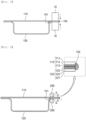
- FIG. 2 is a front view and an enlarged perspective view of a pouch-shaped battery cell according to the present invention.
- the pouch-shaped battery cell sealing apparatus includes a pair of first sealing rollers 200 configured to press and roll an upper part and a lower part of a sealed portion of a pouch-shaped battery cell, respectively, wherein the pair of sealing rollers 200 includes a first sealing roller and a second sealing roller, and the pair of sealing rollers 200 seals the sealed portion of the pouch-shaped battery cell while moving in a direction from an inside to an outside of the sealed portion, such as in direction A.
- the first sealing roller is rotated about a rotation axis in a first direction
- the second sealing roller is rotated about a rotation axis in a second direction, which is opposite the first direction. If the first direction is clockwise, the second direction is counterclockwise, and if the first direction is counterclockwise, the second direction is clockwise.
- the first sealing roller and the second sealing roller press the sealed portion in a heated state.
- the heating temperature of each of the first sealing roller and the second sealing roller is higher than the melting temperature of the inner adhesive layers 113 and 123 of the laminate sheet constituting the pouch-shaped battery cell.
- the temperature of each of the first sealing roller and the second sealing roller may be 100°C to 200°C.
- the inner adhesive layers 113 and 123 are melted, and the inner adhesive layers 113 and 123 are pushed in direction A in a melted state.
- the inner adhesive layers form a round ball-shaped mass. Since such a round ball-shaped mass is formed as the result of the inner adhesive layers including the polymer material being melted and solidified, the round ball-shaped mass is called a polyball in this specification.
- the molten inner adhesive layers are moved inward and outward from the part of the sealed portion in contact with the pair of sealing rollers, and at least a part of each of the inner adhesive layers 113 and 123 may be moved in a direction toward an electrode assembly receiving portion, which is opposite direction A.
- the molten materials of the inner adhesive layers 113 and 123 melted by the pair of sealing rollers 200 of the pouch-shaped battery cell sealing apparatus are pushed to the inside and the outside of the sealed portion, respectively, to form an inner polyball 101 and an outer polyball 102.
- the pair of sealing rollers 20 pushes the molten inner adhesive layers 113 and 123 in a direction toward the outside of the sealed portion while being moved in direction A, the size of the outer polyball 102 is formed so as to greater than the size of the inner polyball 101.
- the pair of sealing rollers 200 is moved in the direction from the inside to the outside of the sealed portion until the molten inner adhesive layers is moved to an outer end of the sealed portion, and the outer polyball 102 protrudes outward from outer peripheral ends of the upper case 110 and the lower case 120 to form a round ball shape. Consequently, the outer polyball 102 is added to end surfaces of the metal layers 112 and 122. Since the end surfaces of the metal layers 112 and 122 are not exposed, as described above, it is possible to prevent corrosion of the metal layers 112, 122 due to exposure thereof.
- the diameter of each of the first sealing roller and the second sealing roller may be 50% or less of the width of the sealed portion.
- FIG. 3 is a flowchart of a pouch-shaped battery cell sealing method according to the present invention.
- the pouch-shaped battery cell sealing method using the pouch-shaped battery cell sealing apparatus includes disposing an upper case 110 and a lower case 120 so as to face each other, (a) disposing a sealed portion of a pouch-shaped battery cell between a pair of sealing rollers 200, and (b) moving the pair of sealing rollers 200 from an inside to an outside of the sealed portion in direction A while independently rotating a first sealing roller and a second sealing roller constituting the pair of sealing rollers 200, wherein, in step (b), the pair of sealing rollers 200 may be rotated and moved in a heated state.
- the pair of sealing rollers 200 is not disposed, and sealed portions of the upper case 110 and the lower case 120 are disposed so as to face each other.
- a gap is shown to be formed between the upper case 110 and the lower case 120 for ease of description, but the upper case and the lower case may be in tight contact with each other.
- the first sealing roller and the second sealing roller have the same rotation speed and movement speed, the first sealing roller is rotated and moved while downwardly pressing the sealed portion, and the second sealing roller is rotated and moved while upwardly pressing the sealed portion.
- the inner adhesive layer of the laminate sheet is melted and moved in a direction toward the outside of the sealed portion by the pair of sealing rollers.
- the first sealing roller and the second sealing roller are moved in direction A while pressing the upper case 110 and the lower case 120 in a direction in which the first sealing roller and the second sealing roller approach each other in the state in which the first sealing roller and the second sealing roller are disposed at the same position in the vertical direction, and in the part pressed by the pair of sealing rollers 200, the inner adhesive layers 113 and 123 melt and consolidate and the thickness thereof is reduced.
- the molten materials constituting the inner adhesive layers 113 and 123 are agglomerated and solidified at the outer end of the sealed portion to form the outer polyball 102.
- the inner adhesive layers 113 and 123 are fused to each other, and the thickness of the inner adhesive layers 113 and 123 after fusion is less than the sum of the thicknesses of the inner adhesive layers 113 and 123 before fusion, and a polyball is formed by the reduced thickness of the inner adhesive layers 113 and 123.
- the thickness of the inner adhesive layers 113, 123 is reduced after fusion, as described above, and therefore the sealing force between the upper case 110 and the lower case 12 is reduced.
- the sealing force of the pouch-shaped battery case is increased as the thickness of the inner adhesive layers 113 and 123 is increased and the size of the inner polyballs is increased.
- the sealing force of the pouch-shaped battery case may be reduced by not only reducing the thickness of the inner adhesive layers 113 and 123 but also increasing the size of the outer polyball 102 so as to be greater than the size of the inner polyball 101.
Landscapes
- Chemical & Material Sciences (AREA)
- Electrochemistry (AREA)
- General Chemical & Material Sciences (AREA)
- Chemical Kinetics & Catalysis (AREA)
- Engineering & Computer Science (AREA)
- Mechanical Engineering (AREA)
- Inorganic Chemistry (AREA)
- Thermal Sciences (AREA)
- Physics & Mathematics (AREA)
- Manufacturing & Machinery (AREA)
- Sealing Battery Cases Or Jackets (AREA)
- Lining Or Joining Of Plastics Or The Like (AREA)
- Secondary Cells (AREA)
Abstract
Description
- This application claims the benefit of priority to
Korean Patent Application No. 2022-0152306 filed on November 15, 2022 - The present invention relates to a pouch-shaped battery cell sealing apparatus including a pair of sealing rollers, a sealing method using the same, and a pouch-shaped battery cell manufactured using the same. More particularly, the present invention relates to a pouch-shaped battery cell sealing apparatus including a pair of sealing rollers capable of rapidly discharging gas when the internal pressure of a pouch-shaped battery cell increases, thereby preventing explosion of the pouch-shaped battery cell, a sealing method using the same, and a pouch-shaped battery cell manufactured using the same.
- A lithium secondary battery, which is capable of being charged and discharged, has been widely used as an energy source for wireless mobile devices or wearable devices, which are worn on bodies, and has also been used as an energy source for electric vehicles and hybrid electric vehicles presented as alternatives to existing gasoline and diesel vehicles, which cause air pollution.
- The lithium secondary battery may be classified as a prismatic battery cell including a metal can-shaped case, a cylindrical battery cell including a metal can-shaped case, or a pouch-shaped battery cell including a case formed of a laminate sheet. Thereamong, the pouch-shaped battery cell is most commonly used due to easy deformation and an increase in energy density when stored and stacked.
- In the lithium secondary battery, a side reaction occurs between the surface of an electrode and an electrolytic solution during repeated charging and discharging, and if gas generated at this time is not discharged from the battery case, the battery case may swell or may be deformed.
- In particular, since the pouch-shaped battery cell includes no separate venting structure, unlike the cylindrical battery cell, which includes a safety vent, venting may occur at a part of a thermally fused outer periphery at which gas is concentrated or adhesion due to thermal fusion is low.
- In general, the pouch-shaped battery cell is manufactured by shaping a laminated sheet including an outer resin layer, a metal layer, and an inner adhesive layer into a pouch-shaped battery case, receiving an electrode assembly in the pouch-shaped battery case, and sealing the pouch-shaped battery case.
- The laminate sheet may have a more complex and varied layered structure depending on implementation of the laminate sheet and the environment to which the laminate sheet is applied.
- In order to seal the pouch-shaped battery case, an outer periphery of the pouch-shaped battery case is pressed using a heating block configured to provide heat and pressure. As a result, the inner adhesive layer is melted, whereby inner adhesive layers of an upper case and a lower case, which are stacked on top of each other, are thermally fused to form a seal.
-
FIG. 1 is a front view of a conventional pouch-shaped battery cell and an apparatus for sealing the same. - Referring to
FIG. 1 , a pouch-shaped battery case includes anupper case 110 and alower case 120. Outer peripheries of theupper case 110 and thelower case 120 are disposed between a pair ofsealing tools 10, and then pressed and heated with the pair ofsealing tools 10 to form a sealed portion. Each of theupper case 110 and thelower case 120 is made of a laminate sheet in which an outer resin layer, a metal layer, and an inner adhesive layer are sequentially laminated, and the inner adhesive layer of theupper case 110 and the inner adhesive layer of thelower case 120 are melted. - Under the pressure of the
sealing tools 10, which heat and press the sealed portion, the melted inner adhesive layers are pushed inward and outward relative to the sealed portion, whereby aninner polyball 101 and anouter polyball 102 are formed. - The pair of
sealing tools 10 is configured to press the entire area of the sealed portion at once, and the size of theinner polyball 101 is formed so as to be greater than the size of theouter polyball 102 since there is a lot of movement of the inner adhesive layer in an inward direction where a wide empty space is formed in a direction toward an electrode assembly receiving portion. When theinner polyball 101 has a larger size, as described above, venting of the pouch-shaped battery case is difficult even though the internal pressure of the pouch-shaped battery cell increases, whereby the pressure in the pouch-shaped battery case gradually increases. - If external impact is applied to the pouch-shaped battery case while the pouch-shaped battery case continuously swells or if a chemical chain reaction, such as thermal runaway, occurs due to electrical short circuit, the pouch-shaped battery cell may explode.
- In this regard, Patent Document 1 relates to a battery cell including a battery case made of a laminate sheet having a structure in which a first resin layer, a metal layer, and a second resin layer are sequentially laminated, wherein the laminate sheet includes a first sheet portion and a second sheet portion facing each other to form a surplus sealed portion, and at least a part of the surplus sealed portion includes a resin layer fusion portion formed by the first resin layer of the first sheet portion and the first resin layer of the second sheet portion and a metal layer weld portion formed by an end of the metal layer of the first sheet portion and an end of the metal layer of the second sheet portion.
- Also, in Patent Document 1, a first sealing tool and a second sealing tool with a semicircular shape convex in directions toward the first sheet portion and the second sheet portion are used, in a sealed portion formed by the first sealing tool and the second sealing tool, a resin layer fusion portion is formed inside the sealed portion adjacent to an electrode assembly, whereby sealing force of the battery cell is increased.
- Therefore, there is a need to develop an apparatus for sealing a pouch-shaped battery cell configured to have a structure in which the sealing pressure of a sealed portion formed at an outer periphery of a pouch-shaped battery case is nonuniform, whereby venting easily occurs, a sealing method using the same, and a pouch-shaped battery cell manufactured using the same.
- (Patent Document 1)
Korean Patent Application Publication No. 2016-0073097 - The present invention has been made in view of the above problems, and it is an object of the present invention to provide a pouch-shaped battery cell sealing apparatus capable of reducing the thickness of an inner adhesive layer of a sealed portion of a pouch-shaped battery cell such that venting can easily occur by reducing a venting pressure in the sealed portion, a sealing method using the same, and a pouch-shaped battery cell manufactured using the same.
- A pouch-shaped battery cell sealing apparatus according to the present invention to accomplish the above object includes a pair of sealing rollers configured to press and roll an upper part and a lower part of a sealed portion of a pouch-shaped battery cell, respectively, wherein the pair of sealing rollers includes a first sealing roller and a second sealing roller, and the pair of sealing rollers are configured to seal the sealed portion while moving in a direction from the inside to the outside of the sealed portion.
- The first sealing roller may be rotated about a rotation axis in a first direction, and the second sealing roller may be rotated about a rotation axis in a second direction opposite the first direction.
- The first sealing roller and the second sealing roller may be configured to press the sealed portion, the first and second sealing rollers being in a heated state.
- The heating temperature of each of the first and second sealing rollers may be higher than the melting temperature of an inner adhesive layer of a laminate sheet constituting the pouch-shaped battery cell.
- The diameter of each of the first and second sealing rollers may be 50% or less than the width of the sealed portion.
- There is provided a pouch-shaped battery cell sealing method using the pouch-shaped battery cell sealing apparatus, the pouch-shaped battery cell sealing method including (a) disposing a sealed portion of a pouch-shaped battery cell between a pair of sealing rollers and (b) moving the pair of sealing rollers from the inside to the outside of the sealed portion while independently rotating a first sealing roller and a second sealing roller constituting the pair of sealing rollers, wherein, in step (b), the pair of sealing rollers is rotated and moved in a heated state.
- Each of the first and second sealing rollers may have a rotation speed being the same, wherein each of the first and second sealing rollers has a movement speed being the same, the first sealing roller may be rotated and moved while downwardly pressing the sealed portion, and the second sealing roller may be rotated and moved while upwardly pressing the sealed portion.
- In the sealed portion, an inner adhesive layer of a laminate sheet of the sealed portion may be melted and moved in a direction toward the outside of the sealed portion by the pair of sealing rollers.
- The pair of sealing rollers may move along a direction from the inside to the outside of the sealed portion, so as to move a portion of the inner adhesive layer in a molten state to an outer end of the sealed portion.
- There is provided a pouch-shaped battery cell manufactured using the pouch-shaped battery cell sealing apparatus, wherein the pouch-shaped battery cell includes a pouch-shaped battery case including a laminate sheet including an outer resin layer, a metal layer, and an inner adhesive layer, the pouch-shaped battery case has a sealed portion including a portion of the inner adhesive layer in a thermally fused state and disposed at outer peripheries of an upper case and a lower case, the portion of the inner adhesive layer melted by the pair of sealing rollers of the pouch-type battery cell sealing apparatus is pushed to the inside and the outside of the sealed portion to form an inner polyball and an outer polyball, and the size of the outer polyball is greater than the size of the inner polyball.
- An end surface of the metal layer of the pouch-shaped battery case may not be exposed by the outer polyball.
- In addition, the present invention may provide various combinations of the above solving means.
- As is apparent from the above description, in the present invention, an inner adhesive layer of a laminate sheet in a sealed portion of a pouch-shaped battery cell is melted and moved to an outside of the sealed portion, whereby the size of an outer polyball formed at the outside of the sealed portion is formed so as to be greater than the size of an inner polyball formed at an inside of the sealed portion.
- Therefore, venting may easily occur even in the state in which the pressure in the pouch-shaped battery cell is low, whereby it is possible to prevent swelling and deformation of the pouch-shaped battery cell and prevent explosion of the pouch-shaped battery cell.
-
-
FIG. 1 is a front view of a conventional pouch-shaped battery cell and an apparatus for sealing the same. -
FIG. 2 is a front view and an enlarged perspective view of a pouch-shaped battery cell according to the present invention. -
FIG. 3 is a flowchart of a pouch-shaped battery cell sealing method according to the present invention. - Now, preferred embodiments of the present invention will be described in detail with reference to the accompanying drawings such that the preferred embodiments of the present invention can be easily implemented by a person having ordinary skill in the art to which the present invention pertains. In describing the principle of operation of the preferred embodiments of the present invention in detail, however, a detailed description of known functions and configurations incorporated herein will be omitted when the same may obscure the subject matter of the present invention.
- In addition, the same reference numbers will be used throughout the drawings to refer to parts that perform similar functions or operations. In the case in which one part is said to be connected to another part throughout the specification, not only may the one part be directly connected to the other part, but also, the one part may be indirectly connected to the other part via a further part. In addition, that a certain element is included does not mean that other elements are excluded, but means that such elements may be further included unless mentioned otherwise.
- In addition, a description to embody elements through limitation or addition may be applied to all inventions, unless particularly restricted, and does not limit a specific invention.
- Also, in the description of the invention and the claims of the present application, singular forms are intended to include plural forms unless mentioned otherwise.
- Also, in the description of the invention and the claims of the present application, "or" includes "and" unless mentioned otherwise. Therefore, "including A or B" means three cases, namely, the case including A, the case including B, and the case including A and B.
- Embodiments of the present invention will be described in detail with reference to the accompanying drawings.
- A pouch-shaped battery cell includes a pouch-shaped battery case made of a laminate sheet including an
outer resin layer metal layer adhesive layer upper case 110 and alower case 120. Theupper case 110 and thelower case 120 may be formed as a single member in which the upper case and the lower case are connected to each other at an outer periphery of one side of each thereof, or an upper case and a lower case separated from each other may be coupled to each other by thermal fusion to form a sealed portion. - The outer resin layer may include polyethylene terephthalate or stretched nylon, aluminum or an aluminum alloy may be used as the metal layer, and the inner adhesive layer may include polypropylene.
-
FIG. 2 is a front view and an enlarged perspective view of a pouch-shaped battery cell according to the present invention. - Referring to
FIG. 2 , the pouch-shaped battery cell sealing apparatus according to the present invention includes a pair offirst sealing rollers 200 configured to press and roll an upper part and a lower part of a sealed portion of a pouch-shaped battery cell, respectively, wherein the pair ofsealing rollers 200 includes a first sealing roller and a second sealing roller, and the pair ofsealing rollers 200 seals the sealed portion of the pouch-shaped battery cell while moving in a direction from an inside to an outside of the sealed portion, such as in direction A. - At this time, the first sealing roller is rotated about a rotation axis in a first direction, and the second sealing roller is rotated about a rotation axis in a second direction, which is opposite the first direction. If the first direction is clockwise, the second direction is counterclockwise, and if the first direction is counterclockwise, the second direction is clockwise.
- In the case of
FIG. 2 , in which the first sealing roller is rotated clockwise and the second sealing roller is rotated counterclockwise, the first sealing roller and the second sealing roller are moved in direction A simultaneously with the clockwise and counterclockwise rotation. - The first sealing roller and the second sealing roller press the sealed portion in a heated state. The heating temperature of each of the first sealing roller and the second sealing roller is higher than the melting temperature of the inner
adhesive layers - When the laminate sheet is pressed and heated by the first sealing roller and the second sealing roller, therefore, the inner
adhesive layers adhesive layers - When the sealed portion is first pressed with the pair of sealing rollers, however, the molten inner adhesive layers are moved inward and outward from the part of the sealed portion in contact with the pair of sealing rollers, and at least a part of each of the inner
adhesive layers - As a result, the molten materials of the inner
adhesive layers rollers 200 of the pouch-shaped battery cell sealing apparatus are pushed to the inside and the outside of the sealed portion, respectively, to form aninner polyball 101 and anouter polyball 102. However, since the pair of sealing rollers 20 pushes the molten inneradhesive layers outer polyball 102 is formed so as to greater than the size of theinner polyball 101. - Meanwhile, the pair of sealing
rollers 200 is moved in the direction from the inside to the outside of the sealed portion until the molten inner adhesive layers is moved to an outer end of the sealed portion, and theouter polyball 102 protrudes outward from outer peripheral ends of theupper case 110 and thelower case 120 to form a round ball shape. Consequently, theouter polyball 102 is added to end surfaces of the metal layers 112 and 122. Since the end surfaces of the metal layers 112 and 122 are not exposed, as described above, it is possible to prevent corrosion of the metal layers 112, 122 due to exposure thereof. - Meanwhile, in the pair of sealing
rollers 200, the diameter of each of the first sealing roller and the second sealing roller may be 50% or less of the width of the sealed portion. -
FIG. 3 is a flowchart of a pouch-shaped battery cell sealing method according to the present invention. - Referring to
FIG. 3 , the pouch-shaped battery cell sealing method using the pouch-shaped battery cell sealing apparatus according to the present invention includes disposing anupper case 110 and alower case 120 so as to face each other, (a) disposing a sealed portion of a pouch-shaped battery cell between a pair of sealingrollers 200, and (b) moving the pair of sealingrollers 200 from an inside to an outside of the sealed portion in direction A while independently rotating a first sealing roller and a second sealing roller constituting the pair of sealingrollers 200, wherein, in step (b), the pair of sealingrollers 200 may be rotated and moved in a heated state. - In the first step shown in
FIG. 3 , the pair of sealingrollers 200 is not disposed, and sealed portions of theupper case 110 and thelower case 120 are disposed so as to face each other. InFIG. 3 , a gap is shown to be formed between theupper case 110 and thelower case 120 for ease of description, but the upper case and the lower case may be in tight contact with each other. - The first sealing roller and the second sealing roller have the same rotation speed and movement speed, the first sealing roller is rotated and moved while downwardly pressing the sealed portion, and the second sealing roller is rotated and moved while upwardly pressing the sealed portion.
- In this process, in the sealed portion, the inner adhesive layer of the laminate sheet is melted and moved in a direction toward the outside of the sealed portion by the pair of sealing rollers.
- The first sealing roller and the second sealing roller are moved in direction A while pressing the
upper case 110 and thelower case 120 in a direction in which the first sealing roller and the second sealing roller approach each other in the state in which the first sealing roller and the second sealing roller are disposed at the same position in the vertical direction, and in the part pressed by the pair of sealingrollers 200, the inneradhesive layers rollers 200, therefore, the molten materials constituting the inneradhesive layers outer polyball 102. - At this time, the inner
adhesive layers adhesive layers adhesive layers adhesive layers - The thickness of the inner
adhesive layers upper case 110 and the lower case 12 is reduced. - That is, the sealing force of the pouch-shaped battery case is increased as the thickness of the inner
adhesive layers adhesive layers outer polyball 102 so as to be greater than the size of theinner polyball 101. - When the pouch-shaped battery cell according to the present invention is used, therefore, rapid venting may be achieved even though the internal pressure of the pouch-type battery cell is low, whereby it is possible to prevent problems such as explosion due to delayed venting of the pouch-shaped battery cell.
- Those skilled in the art to which the present invention pertains will appreciate that various applications and modifications are possible within the category of the present invention based on the above description.
-
- 10: Sealing tool
- 101: Inner polyball
- 102: Outer polyball
- 110: Upper case
- 111, 121: Outer resin layers
- 112, 122: Metal layers
- 113, 123: Inner adhesive layers
- 120: Lower case
- 200: Pair of sealing rollers
Claims (11)
- A pouch-shaped battery cell sealing apparatus comprising:a pair of sealing rollers configured to press and roll an upper part and a lower part of a sealed portion of a pouch-shaped battery cell, respectively,wherein the pair of sealing rollers comprises a first sealing roller and a second sealing roller,wherein the pair of sealing rollers are configured to seal the sealed portion while moving in a direction from an inside to an outside of the sealed portion.
- The pouch-shaped battery cell sealing apparatus according to claim 1, whereinthe first sealing roller is rotated about a rotation axis in a first direction, andthe second sealing roller is rotated about a rotation axis in a second direction opposite the first direction.
- The pouch-shaped battery cell sealing apparatus according to claim 1, wherein the first sealing roller and the second sealing roller are configured to press the sealed portion, the first and second sealing rollers being in a heated state.
- The pouch-shaped battery cell sealing apparatus according to claim 3, wherein a heating temperature of each of the first and second sealing rollers is higher than a melting temperature of an inner adhesive layer of a laminate sheet constituting the pouch-shaped battery cell.
- The pouch-shaped battery cell sealing apparatus according to claim 1, wherein a diameter of each of the first and second sealing rollers is 50% or less than a width of the sealed portion.
- A pouch-shaped battery cell sealing method using the pouch-shaped battery cell sealing apparatus according to any one of claims 1 to 5, the pouch-shaped battery cell sealing method comprising:(a) disposing a sealed portion of a pouch-shaped battery cell between a pair of sealing rollers; and(b) moving the pair of sealing rollers from an inside to an outside of the sealed portion while independently rotating a first sealing roller and a second sealing roller constituting the pair of sealing rollers, whereinin step (b), the pair of sealing rollers is rotated and moved in a heated state.
- The pouch-shaped battery cell sealing method according to claim 6, whereineach of the first and second sealing rollers has a rotation speed being the same,,wherein each of the first and second sealing rollers has a movement speed being the same,the first sealing roller is rotated and moved while downwardly pressing the sealed portion, andthe second sealing roller is rotated and moved while upwardly pressing the sealed portion.
- The pouch-shaped battery cell sealing method according to claim 6, wherein, in the sealed portion, an inner adhesive layer of a laminate sheet of the sealed portion is melted and moved in a direction toward the outside of the sealed portion by the pair of sealing rollers.
- The pouch-shaped battery cell sealing method according to claim 8, wherein the pair of sealing rollers move along a direction from the inside to the outside of the sealed portion, so as to move a portion of the inner adhesive layer in a molten state to an outer end of the sealed portion.
- A pouch-shaped battery cell manufactured using the pouch-shaped battery cell sealing apparatus according to any one of claims 1 to 5, whereinthe pouch-shaped battery cell comprises a pouch-shaped battery case including a laminate sheet comprising an outer resin layer, a metal layer, and an inner adhesive layer,the pouch-shaped battery case has a sealed portion including a portion of the inner adhesive layer in a thermally fused state and disposed at outer peripheries of an upper case and a lower case,the portion of the inner adhesive layer melted by the pair of sealing rollers of the pouch-type battery cell sealing apparatus is pushed to an inside and an outside of the sealed portion to form an inner polyball and an outer polyball, anda size of the outer polyball is greater than a size of the inner polyball.
- The pouch-shaped battery cell according to claim 10, wherein an end surface of the metal layer of the pouch-shaped battery case is not exposed by the outer polyball.
Applications Claiming Priority (2)
| Application Number | Priority Date | Filing Date | Title |
|---|---|---|---|
| KR1020220152306A KR20240070869A (en) | 2022-11-15 | 2022-11-15 | Pouch-type Battery Cell Sealing Device Comprising a Pair of Sealing Rollers, Sealing Method Using the Same and Pouch-type Battery Cell Manufactured Using the Same |
| PCT/KR2023/018397 WO2024106956A1 (en) | 2022-11-15 | 2023-11-15 | Pouch-type battery cell sealing device comprising pair of sealing rollers, sealing method using same, and pouch-type battery cell manufactured using same |
Publications (3)
| Publication Number | Publication Date |
|---|---|
| EP4501592A1 true EP4501592A1 (en) | 2025-02-05 |
| EP4501592A4 EP4501592A4 (en) | 2025-08-13 |
| EP4501592B1 EP4501592B1 (en) | 2026-04-01 |
Family
ID=91084958
Family Applications (1)
| Application Number | Title | Priority Date | Filing Date |
|---|---|---|---|
| EP23892021.9A Active EP4501592B1 (en) | 2022-11-15 | 2023-11-15 | Pouch-shaped battery cell sealing apparatus including pair of sealing rollers, sealing method using the same, and pouch-shaped battery cell manufactured using the same |
Country Status (6)
| Country | Link |
|---|---|
| US (1) | US20250158174A1 (en) |
| EP (1) | EP4501592B1 (en) |
| JP (1) | JP7779493B2 (en) |
| KR (1) | KR20240070869A (en) |
| CN (1) | CN118541258A (en) |
| WO (1) | WO2024106956A1 (en) |
Family Cites Families (10)
| Publication number | Priority date | Publication date | Assignee | Title |
|---|---|---|---|---|
| WO2010141493A2 (en) * | 2009-06-01 | 2010-12-09 | Add-Vision, Inc. | Formulations for improved electrodes for electronic devices |
| KR101417152B1 (en) * | 2009-10-09 | 2014-08-07 | 주식회사 엘지화학 | Method for manufacturing pouch type battery and sealing device for pouch |
| JP5693327B2 (en) | 2011-03-29 | 2015-04-01 | Fdk鳥取株式会社 | Method for producing electrochemical element |
| KR101838315B1 (en) * | 2013-10-18 | 2018-03-13 | 주식회사 엘지화학 | Method For Manufacturing Pouch Type Lithium Secondary Battery |
| KR20160073097A (en) | 2014-12-16 | 2016-06-24 | 주식회사 엘지화학 | Battery Cell Having Welded Sealing Surplus Portion |
| CN111866757B (en) | 2020-07-17 | 2023-03-28 | 腾讯科技(深圳)有限公司 | Communication method, device, medium and electronic equipment for multicast broadcast service |
| ES3060204T3 (en) | 2020-11-13 | 2026-03-25 | Lg Energy Solution Ltd | Pouch-shaped battery cell manufacturing method including secondary sealing and pouch-shaped battery cell manufactured thereby |
| KR102784302B1 (en) * | 2020-11-13 | 2025-03-21 | 주식회사 엘지에너지솔루션 | Method of manufacturing pouch-type battery cell comprising two-times sealing and pouch-type battery cell manufactured thereby |
| KR102846416B1 (en) * | 2021-01-08 | 2025-08-14 | 주식회사 엘지에너지솔루션 | Welding Device, Welding Method Using the Same, and Electrode Assembly Manufactured by Welding Method |
| JP7821668B2 (en) | 2022-03-31 | 2026-02-27 | 本田技研工業株式会社 | secondary battery |
-
2022
- 2022-11-15 KR KR1020220152306A patent/KR20240070869A/en active Pending
-
2023
- 2023-11-15 EP EP23892021.9A patent/EP4501592B1/en active Active
- 2023-11-15 JP JP2024559960A patent/JP7779493B2/en active Active
- 2023-11-15 CN CN202380016291.0A patent/CN118541258A/en active Pending
- 2023-11-15 WO PCT/KR2023/018397 patent/WO2024106956A1/en not_active Ceased
- 2023-11-15 US US18/839,115 patent/US20250158174A1/en active Pending
Also Published As
| Publication number | Publication date |
|---|---|
| CN118541258A (en) | 2024-08-23 |
| JP2025512354A (en) | 2025-04-17 |
| US20250158174A1 (en) | 2025-05-15 |
| KR20240070869A (en) | 2024-05-22 |
| WO2024106956A1 (en) | 2024-05-23 |
| JP7779493B2 (en) | 2025-12-03 |
| EP4501592A4 (en) | 2025-08-13 |
| EP4501592B1 (en) | 2026-04-01 |
Similar Documents
| Publication | Publication Date | Title |
|---|---|---|
| EP3098877B1 (en) | Battery cell comprising circumferential surface sealing part having sealing line | |
| JP7062197B2 (en) | Venting device | |
| EP4094928B1 (en) | Apparatus and method for folding a side | |
| EP3859814B1 (en) | Pouch type battery cell and manufacturing method thereof | |
| US20240097245A1 (en) | Battery Cell Including Sealed Portion Having Embossed Pattern Formed Thereon and Sealing Block for Manufacturing the Same | |
| EP1035598A1 (en) | Coin-shaped cell and method for producing the same | |
| KR102784302B1 (en) | Method of manufacturing pouch-type battery cell comprising two-times sealing and pouch-type battery cell manufactured thereby | |
| EP4501592A1 (en) | Pouch-type battery cell sealing device comprising pair of sealing rollers, sealing method using same, and pouch-type battery cell manufactured using same | |
| US20250149694A1 (en) | Battery Case, Battery Case Shaping Apparatus, and Secondary Battery Manufacturing Method | |
| CN115485913B (en) | Method for manufacturing soft-pack type battery cell and soft-pack type battery cell manufactured thereby | |
| US20250293356A1 (en) | Pouch-Shaped Battery Cell and Apparatus for Sealing Pouch-Shaped Battery Case Used to Manufacture the Same | |
| EP4404362A1 (en) | Pouch-type battery cell and pouch-type battery case sealing device for manufacturing same | |
| EP4113709A1 (en) | Battery case sheet in which gas pocket part is formed in traveling direction, battery cell manufactured using same, and method for manufacturing battery cell | |
| JP2023542175A (en) | Battery case sealing device and secondary battery manufactured using the same | |
| US20250309321A1 (en) | Apparatus for forming folding guide line and battery cell | |
| KR101400088B1 (en) | Manufacturing of Battery Cell by Roll-Pressing Process | |
| US20250385347A1 (en) | Grid-like pattern sealing device and pouch-type battery manufactured using the same | |
| EP4089809A1 (en) | Battery cell and manufacturing apparatus therefor | |
| KR20220092391A (en) | Battery cell and manufacturing device for the same | |
| KR20250035928A (en) | Device for bonding lead film and methed for bonding lead film | |
| CN121464527A (en) | System and method for manufacturing battery cell packaging material |
Legal Events
| Date | Code | Title | Description |
|---|---|---|---|
| STAA | Information on the status of an ep patent application or granted ep patent |
Free format text: STATUS: THE INTERNATIONAL PUBLICATION HAS BEEN MADE |
|
| PUAI | Public reference made under article 153(3) epc to a published international application that has entered the european phase |
Free format text: ORIGINAL CODE: 0009012 |
|
| STAA | Information on the status of an ep patent application or granted ep patent |
Free format text: STATUS: REQUEST FOR EXAMINATION WAS MADE |
|
| 17P | Request for examination filed |
Effective date: 20241025 |
|
| AK | Designated contracting states |
Kind code of ref document: A1 Designated state(s): AL AT BE BG CH CY CZ DE DK EE ES FI FR GB GR HR HU IE IS IT LI LT LU LV MC ME MK MT NL NO PL PT RO RS SE SI SK SM TR |
|
| A4 | Supplementary search report drawn up and despatched |
Effective date: 20250711 |
|
| RIC1 | Information provided on ipc code assigned before grant |
Ipc: B29C 65/00 20060101AFI20250707BHEP Ipc: H01M 50/105 20210101ALI20250707BHEP Ipc: H01M 50/124 20210101ALI20250707BHEP Ipc: H01M 50/121 20210101ALI20250707BHEP Ipc: H01M 50/119 20210101ALI20250707BHEP Ipc: H01M 50/183 20210101ALI20250707BHEP Ipc: B29C 65/02 20060101ALI20250707BHEP Ipc: B29L 31/00 20060101ALI20250707BHEP Ipc: B29C 65/18 20060101ALI20250707BHEP Ipc: B29C 65/48 20060101ALI20250707BHEP Ipc: H01M 10/04 20060101ALI20250707BHEP Ipc: H01M 50/186 20210101ALI20250707BHEP Ipc: B29L 31/34 20060101ALN20250707BHEP |
|
| GRAP | Despatch of communication of intention to grant a patent |
Free format text: ORIGINAL CODE: EPIDOSNIGR1 |
|
| STAA | Information on the status of an ep patent application or granted ep patent |
Free format text: STATUS: GRANT OF PATENT IS INTENDED |
|
| RIC1 | Information provided on ipc code assigned before grant |
Ipc: B29C 65/00 20060101AFI20251114BHEP Ipc: H01M 50/105 20210101ALI20251114BHEP Ipc: H01M 50/124 20210101ALI20251114BHEP Ipc: H01M 50/121 20210101ALI20251114BHEP Ipc: H01M 50/119 20210101ALI20251114BHEP Ipc: H01M 50/183 20210101ALI20251114BHEP Ipc: B29C 65/02 20060101ALI20251114BHEP Ipc: B29L 31/00 20060101ALI20251114BHEP Ipc: B29C 65/18 20060101ALI20251114BHEP Ipc: B29C 65/48 20060101ALI20251114BHEP Ipc: H01M 10/04 20060101ALI20251114BHEP Ipc: H01M 50/186 20210101ALI20251114BHEP Ipc: B29L 31/34 20060101ALN20251114BHEP Ipc: B29K 705/02 20060101ALN20251114BHEP |
|
| DAV | Request for validation of the european patent (deleted) | ||
| DAX | Request for extension of the european patent (deleted) | ||
| INTG | Intention to grant announced |
Effective date: 20251215 |
|
| RIC1 | Information provided on ipc code assigned before grant |
Ipc: B29C 65/00 20060101AFI20251208BHEP Ipc: H01M 50/105 20210101ALI20251208BHEP Ipc: H01M 50/124 20210101ALI20251208BHEP Ipc: H01M 50/121 20210101ALI20251208BHEP Ipc: H01M 50/119 20210101ALI20251208BHEP Ipc: H01M 50/183 20210101ALI20251208BHEP Ipc: B29C 65/02 20060101ALI20251208BHEP Ipc: B29C 65/18 20060101ALI20251208BHEP Ipc: B29C 65/48 20060101ALI20251208BHEP Ipc: H01M 10/04 20060101ALI20251208BHEP Ipc: H01M 50/186 20210101ALI20251208BHEP Ipc: B29L 31/34 20060101ALN20251208BHEP Ipc: B29K 705/02 20060101ALN20251208BHEP Ipc: B29L 31/00 20060101ALN20251208BHEP |
|
| P01 | Opt-out of the competence of the unified patent court (upc) registered |
Free format text: CASE NUMBER: UPC_APP_0000306_4501592/2026 Effective date: 20260106 |
|
| GRAS | Grant fee paid |
Free format text: ORIGINAL CODE: EPIDOSNIGR3 |
|
| GRAA | (expected) grant |
Free format text: ORIGINAL CODE: 0009210 |
|
| STAA | Information on the status of an ep patent application or granted ep patent |
Free format text: STATUS: THE PATENT HAS BEEN GRANTED |
|
| AK | Designated contracting states |
Kind code of ref document: B1 Designated state(s): AL AT BE BG CH CY CZ DE DK EE ES FI FR GB GR HR HU IE IS IT LI LT LU LV MC ME MK MT NL NO PL PT RO RS SE SI SK SM TR |
|
| REG | Reference to a national code |
Ref country code: CH Ref legal event code: F10 Free format text: ST27 STATUS EVENT CODE: U-0-0-F10-F00 (AS PROVIDED BY THE NATIONAL OFFICE) Effective date: 20260401 Ref country code: GB Ref legal event code: FG4D |
|
| REG | Reference to a national code |
Ref country code: DE Ref legal event code: R096 Ref document number: 602023014675 Country of ref document: DE |
|
| REG | Reference to a national code |
Ref country code: IE Ref legal event code: FG4D |