EP4501588A1 - Method and apparatus for bending straws - Google Patents
Method and apparatus for bending straws Download PDFInfo
- Publication number
- EP4501588A1 EP4501588A1 EP23189121.9A EP23189121A EP4501588A1 EP 4501588 A1 EP4501588 A1 EP 4501588A1 EP 23189121 A EP23189121 A EP 23189121A EP 4501588 A1 EP4501588 A1 EP 4501588A1
- Authority
- EP
- European Patent Office
- Prior art keywords
- straw
- conveyor
- bending
- straws
- angle
- Prior art date
- Legal status (The legal status is an assumption and is not a legal conclusion. Google has not performed a legal analysis and makes no representation as to the accuracy of the status listed.)
- Withdrawn
Links
Images


Classifications
-
- B—PERFORMING OPERATIONS; TRANSPORTING
- B31—MAKING ARTICLES OF PAPER, CARDBOARD OR MATERIAL WORKED IN A MANNER ANALOGOUS TO PAPER; WORKING PAPER, CARDBOARD OR MATERIAL WORKED IN A MANNER ANALOGOUS TO PAPER
- B31D—MAKING ARTICLES OF PAPER, CARDBOARD OR MATERIAL WORKED IN A MANNER ANALOGOUS TO PAPER, NOT PROVIDED FOR IN SUBCLASSES B31B OR B31C
- B31D5/00—Multiple-step processes for making three-dimensional [3D] articles
- B31D5/0095—Making drinking straws
-
- B—PERFORMING OPERATIONS; TRANSPORTING
- B31—MAKING ARTICLES OF PAPER, CARDBOARD OR MATERIAL WORKED IN A MANNER ANALOGOUS TO PAPER; WORKING PAPER, CARDBOARD OR MATERIAL WORKED IN A MANNER ANALOGOUS TO PAPER
- B31F—MECHANICAL WORKING OR DEFORMATION OF PAPER, CARDBOARD OR MATERIAL WORKED IN A MANNER ANALOGOUS TO PAPER
- B31F1/00—Mechanical deformation without removing material, e.g. in combination with laminating
- B31F1/0003—Shaping by bending, folding, twisting, straightening, flattening or rim-rolling; Shaping by bending, folding or rim-rolling combined with joining; Apparatus therefor
- B31F1/0006—Bending or folding; Folding edges combined with joining; Reinforcing edges during the folding thereof
- B31F1/0032—Bending or folding; Folding edges combined with joining; Reinforcing edges during the folding thereof of tubes
-
- B—PERFORMING OPERATIONS; TRANSPORTING
- B29—WORKING OF PLASTICS; WORKING OF SUBSTANCES IN A PLASTIC STATE IN GENERAL
- B29L—INDEXING SCHEME ASSOCIATED WITH SUBCLASS B29C, RELATING TO PARTICULAR ARTICLES
- B29L2023/00—Tubular articles
- B29L2023/008—Drinking straws
Definitions
- the object of the invention is a method and apparatus for bending straws.
- the invention finds application in the food industry, in particular in the production of drinking straws.
- An apparatus for creasing straws on a drum conveyor is known from the document WO2021/250711A1 .
- the document discloses an apparatus for bending straws wherein each straw is provided with a flexible part configured to allow the straw to be bent.
- the straws are arranged, at least temporarily, on positioning elements, while each bending element allows the corresponding straw to be bent in its flexible part.
- the bending elements of the straws are attached on the circumferential surface of the drum conveyor, on the same surface on which the straw positioning elements are attached. Any change in the specification of the straw, e.g. its length, requires conveyor retooling, involving a replacement of at least some of its components or parts, in order to obtain a dimensionally adapted set of bending and positioning elements.
- a problem occurring in the prior art is the limitation of the possibility of retooling the straw manufacturing equipment when the product specification changes, i.e. the impossibility of manufacturing bendable drinking straws with a significant length of the bendable part of the straw.
- Another problem is a low efficiency of the straw bending apparatuses due to the impossibility of reducing the pitch determining the position of the adjacent slots holding the drinking straws on the circumference of a conveyor, in particular a drum conveyor. This limitation results from the need to maintain a distance between slots that allows the straw to be bent without colliding with adjacent slots.
- the object of the invention is an apparatus for bending straws comprising a first end and a second end connected by an area adapted for bending, the apparatus comprising: a conveyor for conveying the straws provided with a plurality of slots adapted to hold the first ends of the straws, the slots being arranged side by side on a working surface of the conveyor at a first distance, a bending unit provided with a thrust element fixed relative to the conveyor, the thrust element determining the axis of bending of the straw, and the bending element adapted to bend the straws around the thrust element.
- the apparatus according to the invention is characterised in that the first distance between the slots is smaller than the second distance between the second end of the straw and the axis of bending of the straw around the thrust element, and the bending unit is adapted to bend the straw around the thrust element so that the second end of the straw moves along a path running at an angle to the working surface of the conveyor, the angle being selected so that the second end of the straw passes over the straw situated in the adjacent slot.
- the apparatus according to the invention is characterised in that the conveyor for conveying the straws is a drum conveyor.
- the apparatus according to the invention is characterised in that the conveyor for conveying the straws is a linear conveyor.
- the apparatus according to the invention is characterised in that the bending element is arranged on the working surface of the conveyor.
- the apparatus according to the invention is characterised in that the bending element is arranged on the front surface of the conveyor, perpendicular to the working surface of the conveyor.
- the apparatus according to the invention is characterised in that the slots of the conveyor are adapted to hold the first end of the straw parallel to the working surface of the conveyor.
- the apparatus according to the invention is characterised in that the angle of inclination is selected so that the other end of the straw passes over the elements of the adjacent slot.
- the apparatus according to the invention is characterised in that the angle of inclination is selected so that the other end of the straw passes over the adjacent bending element of the adjacent bending unit.
- the apparatus according to the invention is characterised in that the thrust element is positioned perpendicular to the plane of the path along which the other end of the straw moves during bending.
- the apparatus according to the invention is characterised in that the angle of inclination of the path relative to the working surface of the conveyor is in the range of 5-90°.
- the apparatus is characterised in that the angle of inclination of the path relative to the working surface of the conveyor is in the range of 5-45°.
- the apparatus according to the invention is characterised in that the angle of inclination of the path relative to the working surface of the conveyor is variable and is in the range of 5-90°.
- the object of the invention is also a method of bending straws comprising a first end and a second end, connected by an area adapted for bending, comprising steps wherein: the straws are conveyed on the conveyor in the slots adapted to hold the first ends of the straws, the slots are placed side by side on the working surface of the conveyor at a first distance, the conveyor working with a bending unit provided with the thrust element fixed relative to the conveyor, the thrust element determining the axis of bending of the straw, and the bending element adapted to bend the straws around the thrust element.
- the method according to the invention is characterised in that the straws are bent in the bending unit around the thrust element so that the other end of the straw moves along a path running at an angle to the working surface of the conveyor.
- the first distance between the slots is smaller than the second distance between the tip of the second end of the straw and the axis of bending of the straw around the thrust element, and the angle is selected so that the second end of the straw passes over the straw situated in the adjacent
- the invention has the advantage of increasing the efficiency of the apparatus by reducing the distance between the slots in which the straws are secured, in particular when the length of the bent part of the straw is much greater than the distance between the slots holding the straws on the conveyor.
- Fig. 1 diagrammatically shows a straw 2 adapted for bending by creating a bendable area 21 in the straw, for example by making in advance a series of creases to increase the bendability of the oval straw. Straws of this type are used, for example, in the food industry where they are attached to beverage cartons, particularly for children.
- the straw 2 has a first end 20, a bendable area 21 and a second end 22, whereas it is also possible to distinguish the tip of the second end 22 of the straw 2 marked in Fig. 1 with the number 23.
- the straw 2 is placed with the first end 20 in the slot 10 of the apparatus according to invention 1.
- Fig. 1 there are visible holders 9 of the slots 10 holding the straw 2 on the conveyor by which the straw 2 is conveyed during the bending process.
- the conveyor itself is not shown in Fig. 1 .
- the straw 2 is supported on one side by a thrust element 11 which determines the axis X of bending and/or the axis W of rotation around which the straw 2 is bent.
- the thrust element 11 remains stationary with respect to the conveyor and the slot 10 in which the first end of the straw 20 is held.
- a bending element 12 of the bending unit 6 of the apparatus 1 pushes against the straw 2.
- the bending element 12 is adapted to move along a path which, in the top view in Fig. 1 , is marked with an arrow f.
- Fig. 1 there is also marked a second distance d2 between the axis W of the thrust element 11 and the tip 23 of the second end 22 of the straw 2.
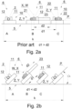
- Figs. 2a and 2b show sequences of movements A, B, C made by an apparatus known from the prior art ( Fig. 2a ) and the apparatus according to the invention ( Fig. 2b ), in both cases bending the straw 2.
- the apparatus shown in Fig. 2a is characterised by a large distance between adjacent slots 10, which adversely affects the efficiency of the apparatus.
- section k of the conveyor 5 it is possible to place three slots 10 arranged at a first distance d1 from one another.
- the first distance d1 between the slots 10 arranged side by side means a distance corresponding to the distance between the longitudinal axes Z of the straws 2 held in the slots 10, with the longitudinal axes Z of the straws 2 coinciding with the longitudinal axes Y of the slots 10. Also possible are embodiments wherein the longitudinal axis Z of the straws 2 will not coincide with the longitudinal axis Y of the slots 10. In that case, the first distance d1 should be measured from the longitudinal axis Z of the straw 2 to the longitudinal axis Z of the next adjacent straw 2.
- the first distance d1 must be greater than the second distance d2 which is measured from the axis of bending X which in this embodiment is the same as the axis W of the thrust element 11 to the tip 23 of the straw 2. If the first distance d1 is equal to or less than the second distance d2, a collision with the adjacent bending unit 6 will occur.
- the straw 2 is conveyed in the slot 10 and is positioned between the thrust element 11 and the bending element 12.
- the bending element 12 makes a rotational movement around the axis of rotation X, which in this embodiment coincides with the axis W of the thrust element 11, and pushing against the other end 22 of the straw 2 causes it to bend in the bendable area 21 and to wind around the thrust element 11, as shown in the next stage C.
- the slots 10 and the bending units 6 are situated in a substantially horizontal plane, during the bending of the straw 2 its second end 22 moves along a path P, also substantially horizontal.
- As horizontal should be assumed a plane parallel to the working surface of a linear (chain, belt) conveyor or tangential to the working surface in the case of a drum conveyor.
- the bending element 12 moves along a path which substantially coincides with the path P along which the other end 22 of the straw 2 moves during bending.
- the bending element 12 returns to its initial position while the other end 22 is held in such position by a holding element (not shown in this figure) or is placed in a groove of the conveyor where it maintains such position until it is transferred to the next stage of the process which may be, for example, packaging.
- the axis W of the thrust element 11 in this embodiment is positioned perpendicular to the plane of the path P.
- the axis W of the thrust element 11 will be positioned at an angle other than 90° to the plane of the path P along which the other end 22 of the straw 2 moves.
- Fig. 2b shows the same sequence A, B, C of bending of the straw 2 in the apparatus according to the invention wherein an inclination of the path P along which the second end 22 of the straw 2 moves by an angle ⁇ is used, which makes it possible to place more slots 10, for example four slots 10, on the same section k of the conveyor 5.
- the angle ⁇ is selected when designing the apparatus according to the invention depending on the distance between the successive straws 2, i.e.
- the angle ⁇ must be sufficiently large so that the path P along which the second end 22 of the straw 2 moves passes over the straw 2 in an adjacent slot 10, whereas by the adjacent slot 10 is meant the slot situated on the side into which the straw 2 is bent.
- the angle ⁇ is selected such that the second end 22 of the straw 2 moves along a path P passing over any element of the adjacent slot 10.
- the angle ⁇ is selected such that the path P along which the second end 22 of the straw 2 moves during bending also passes over the thrust element 11 of the adjacent slot 10 and the bending element 12 of the adjacent bending unit 6.
- the angle ⁇ is determined relative to the surface tangent to the surface of the conveyor on which the slots 10 are arranged. In the case of a linear conveyor, e.g. using a chain or a belt, this surface is the same as the surface of the conveyor, whereas in the case of a drum conveyor, the angle ⁇ is determined relative to the tangent to the working surface of the conveyor at the point of attachment of the slot 10. Details of the determination of the angle ⁇ for the case of a drum conveyor are shown and discussed with reference to Fig. 4 .
- the invention is applicable wherever the first distance d1 is smaller than the second distance d2.
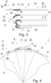
- Fig. 3 diagrammatically shows in more detail the sequence of bending of successive straws 2 in adjacent slots 10 on the conveyor in a top view. It can be seen in successive positions how the bending element 12 pushes against the second end 22 of the straw 2 and bends the straw 2 in the direction f around the thrust element 11.
- This figure shows four straws 2 in different phases of the bending process in the apparatus according to the invention.
- the jaws 9 holding stationary the first end 20 of the straw 2 in the slot 10 of the conveyor are omitted.
- the first straw 2 shown at the top of Fig. 3 is waiting in the initial position for the bending process.
- the first straw 2 is in the position shown and described in detail with reference to Fig. 1 .
- the second straw 2 below is in the first bending phase, the bending element 12 having moved the second end of the straw 22 by an angle of 45° relative to the initial position.
- the straw 2 in the third position is already bent to an angle of about 120° relative to the initial position and passes over the fourth straw 2 situated in the final phase of bending when the bending element has bent the straw 2 by about 180° relative to the initial position.
- the passage of the straw 2 over a straw in the adjacent slot is only possible by routing the straw 2 along a path inclined at an angle ⁇ as shown in Fig. 4 .
- the third straw 2 moves along a path that passes over the elements of the adjacent slot, in particular over the thrust element 11 of the adjacent slot.
- the angle ⁇ should ensure that the second end 22 of the straw 2 also passes over the bending element 12 of the adjacent bending unit 6 operating on the adjacent straw 2.
- the solution according to the invention not only provides an increase in production efficiency by reducing the pitch with which adjacent slots 10 holding the straws 2 can be spaced, but also eliminates the need to retool the machine in the event of a change in the specification of the straw to be produced, making it practically possible to bend straws having the ends 2 of any length.
- Fig. 4 shows, in a side view, a section of the apparatus 1 according to a preferred embodiment wherein the conveyor 5 conveying the straws 2 to be bent is a drum conveyor.
- Fig. 4 shows an inclination of the path P along which the other end 22 of the straw 2 moves by an angle ⁇ .
- the angle ⁇ is measured relative to the working surface 30 of the conveyor 5, in this case the surface tangent to the surface of the drum conveyor or to its envelope, in cases where the drum conveyor is in the form of a prism.
- the working surface 30 of the drum conveyor 5, relative to which the angle ⁇ is determined is perpendicular to the radius r of the drum conveyor 5.
- the angle ⁇ results from the inclination of the entire slot 10, however, the inclination of the path P along which the second end 22 of the straw 2 moves can also be obtained according to the invention in another way, for example by forcing the movement of the bending element 12 along an ascending track so that the path P forms a sector of a spiral or another curve running in three-dimensional space. In this case, the bending element 12 will push against the other end 22 of the straw 2 also from below.
- the angle ⁇ varies along the path P along which the second end 22 of the straw 2 moves so that the second end 22 of the straw 2 traverses portions of the path P at different instantaneous angles.
- Fig. 5 shows the apparatus 1 for bending the straws 2 according to a preferred embodiment of the invention.
- a number of slots 10 adapted to hold the first end 20 of the straws 2 in a position parallel to the working surface 30 of the conveyor are mounted on the drum conveyor 5, the parallelism of the first end 20 of the straw 2 to the working surface 30 of the conveyor being a technological condition advantageously influencing the process of conveying the straws, in particular in the case of drum conveyors.
- the bending unit 6 is fixed by means of a support 8 on the front surface 3 of the conveyor 5 which is preferably perpendicular to the working surface 30 of the conveyor.
- the bending unit 6 comprises two main functional units, the first comprising the thrust element 11 which remains stationary relative to the working surface 30 of the conveyor, and a bending element 12 which moves along a path running substantially around the thrust element 11, the bending element 12 being adapted to bend the second end 22 of the straw 2 around the thrust element 11.
- the bending mechanism 12 by making a rotational movement, pushes against the second end 22 of the straw, causing the straw 2 to bend around the thrust element 11, and the movement of the bent second end 22 of the straw 2 along the path P over the adjacent bending unit 6 and the straw 2 placed in it.
- the drive system actuating the bending element 12 is not shown, typically it is a mechanical system controlled and driven by a cam in combination with a gear system of an arrangement typical of power transmission in conveyors.
- a gear system of an arrangement typical of power transmission in conveyors Such an arrangement may consist of a cam, a gear race, and a gear wheel.
- the apparatus is characterised by being adapted to bend straws comprising a first end and a second end, connected by an area adapted for bending.
- the apparatus comprises the conveyor for conveying the straws provided with a plurality of slots adapted to hold the first ends of the straws, the slots being arranged side by side on the working surface of the conveyor at a first distance, a bending unit provided with the thrust element fixed relative to the conveyor, the thrust element determining the axis of bending of the straw, and the bending element adapted to bend the straws around the thrust element.
- the first distance between the slots is smaller than the second distance between the second end of the straw and the axis of bending of the straw around the thrust element, and the bending unit is adapted to bend the straw around the thrust element so that the second end of the straw moves along a path running at an angle ⁇ relative to the working surface of the conveyor.
- the angle ⁇ is selected so that the second end of the straw passes over the straw situated in the adjacent slot.
- the straw conveyor is a drum conveyor.
- the straw conveyor is a linear conveyor.
- the bending element is arranged on the working surface of the conveyor.
- the apparatus according to the invention is characterised in that the bending element is arranged on the front surface of the conveyor, perpendicular to the working surface of the conveyor.
- the apparatus according to the invention is characterised in that the slots of the conveyor are adapted to hold the first end of the straw parallel to the working surface of the conveyor.
- the angle ⁇ is selected such that the other end of the straw passes over the elements of the adjacent slot.
- the apparatus according to the invention is characterised in that the angle ⁇ is selected such that the other end of the straw passes over the adjacent bending element of the adjacent bending unit.
- the method of bending straws 2 comprising a first end 20 and a second end 22 connected by an area 21 adapted for bending comprises steps wherein the straws 2 are conveyed and the straws 2 are bent along a specific path determined according to the invention.
- the straws 2 are conveyed in slots 10 adapted to hold the first ends of the straws 20, the slots 10 being placed side by side on the working surface 30 of the conveyor 5 at a first distance d1.
- the conveyor works with a bending unit 6 provided with a thrust element 11 fixed relative to the conveyor 5, the thrust element 11 determining the X axis of bending of the straw 2, and a bending element 12 adapted to bend the straws 2 around the thrust element 11.
- the straws 2 are bent around the thrust element 11 so that the second end 22 of the straw 2 moves along a path P running at an angle ⁇ relative to the working surface 30 of the conveyor, the first distance d1 between the slots 10 being smaller than the second distance d2 between the tip 23 of the second end 22 of the straw 2 and the axis X of bending of the straw 2 around the thrust element 11, and the angle ⁇ being selected such that the second end 22 of the straw 2 passes over the straw 2 situated in the adjacent slot 10.
Landscapes
- Engineering & Computer Science (AREA)
- Mechanical Engineering (AREA)
- Shaping Of Tube Ends By Bending Or Straightening (AREA)
Abstract
An apparatus (1), for bending straws (2) having a first end, a second end and a bending section (20, 22, 21 respectively in fig.3), comprises: a conveyor (5) for conveying the straws (2) provided with a plurality of slots (10) arranged side by side on the working surface (30) of the conveyor (5), a bending unit (6) provided with a bending element (12) adapted to bend the straws (2) around a thrust element (11).
The distance (d1 in fig.3) between the slots (10) is smaller than the distance (d2 in fig.3) between the second end (22) of the straw (2) and the bending section (21).
During bending, the straw (2) moves along a path (or plane) at an angle (α) to the working surface (30) of the conveyor (5), such that the second end (22) of the straw (2) passes over the straw (2) in the adjacent slot (10).
Description
- The object of the invention is a method and apparatus for bending straws. The invention finds application in the food industry, in particular in the production of drinking straws.
- An apparatus for creasing straws on a drum conveyor is known from the document
WO2021/250711A1 . The document discloses an apparatus for bending straws wherein each straw is provided with a flexible part configured to allow the straw to be bent. The straws are arranged, at least temporarily, on positioning elements, while each bending element allows the corresponding straw to be bent in its flexible part. It is characteristic for the solution from the prior art that the bending elements of the straws are attached on the circumferential surface of the drum conveyor, on the same surface on which the straw positioning elements are attached. Any change in the specification of the straw, e.g. its length, requires conveyor retooling, involving a replacement of at least some of its components or parts, in order to obtain a dimensionally adapted set of bending and positioning elements. - A problem occurring in the prior art is the limitation of the possibility of retooling the straw manufacturing equipment when the product specification changes, i.e. the impossibility of manufacturing bendable drinking straws with a significant length of the bendable part of the straw. Another problem is a low efficiency of the straw bending apparatuses due to the impossibility of reducing the pitch determining the position of the adjacent slots holding the drinking straws on the circumference of a conveyor, in particular a drum conveyor. This limitation results from the need to maintain a distance between slots that allows the straw to be bent without colliding with adjacent slots.
- The object of the invention is an apparatus for bending straws comprising a first end and a second end connected by an area adapted for bending, the apparatus comprising: a conveyor for conveying the straws provided with a plurality of slots adapted to hold the first ends of the straws, the slots being arranged side by side on a working surface of the conveyor at a first distance, a bending unit provided with a thrust element fixed relative to the conveyor, the thrust element determining the axis of bending of the straw, and the bending element adapted to bend the straws around the thrust element. The apparatus according to the invention is characterised in that the first distance between the slots is smaller than the second distance between the second end of the straw and the axis of bending of the straw around the thrust element, and the bending unit is adapted to bend the straw around the thrust element so that the second end of the straw moves along a path running at an angle to the working surface of the conveyor, the angle being selected so that the second end of the straw passes over the straw situated in the adjacent slot.
- Preferably, the apparatus according to the invention is characterised in that the conveyor for conveying the straws is a drum conveyor.
- Preferably, the apparatus according to the invention is characterised in that the conveyor for conveying the straws is a linear conveyor.
- The apparatus according to the invention is characterised in that the bending element is arranged on the working surface of the conveyor.
- The apparatus according to the invention is characterised in that the bending element is arranged on the front surface of the conveyor, perpendicular to the working surface of the conveyor.
- The apparatus according to the invention is characterised in that the slots of the conveyor are adapted to hold the first end of the straw parallel to the working surface of the conveyor.
- Preferably, the apparatus according to the invention is characterised in that the angle of inclination is selected so that the other end of the straw passes over the elements of the adjacent slot.
- Preferably, the apparatus according to the invention is characterised in that the angle of inclination is selected so that the other end of the straw passes over the adjacent bending element of the adjacent bending unit.
- The apparatus according to the invention is characterised in that the thrust element is positioned perpendicular to the plane of the path along which the other end of the straw moves during bending.
- The apparatus according to the invention is characterised in that the angle of inclination of the path relative to the working surface of the conveyor is in the range of 5-90°.
- Preferably, the apparatus is characterised in that the angle of inclination of the path relative to the working surface of the conveyor is in the range of 5-45°.
- The apparatus according to the invention is characterised in that the angle of inclination of the path relative to the working surface of the conveyor is variable and is in the range of 5-90°.
- The object of the invention is also a method of bending straws comprising a first end and a second end, connected by an area adapted for bending, comprising steps wherein: the straws are conveyed on the conveyor in the slots adapted to hold the first ends of the straws, the slots are placed side by side on the working surface of the conveyor at a first distance, the conveyor working with a bending unit provided with the thrust element fixed relative to the conveyor, the thrust element determining the axis of bending of the straw, and the bending element adapted to bend the straws around the thrust element. The method according to the invention is characterised in that the straws are bent in the bending unit around the thrust element so that the other end of the straw moves along a path running at an angle to the working surface of the conveyor. The first distance between the slots is smaller than the second distance between the tip of the second end of the straw and the axis of bending of the straw around the thrust element, and the angle is selected so that the second end of the straw passes over the straw situated in the adjacent slot.
- The invention has the advantage of increasing the efficiency of the apparatus by reducing the distance between the slots in which the straws are secured, in particular when the length of the bent part of the straw is much greater than the distance between the slots holding the straws on the conveyor.
- The object of the invention is shown in more detail in a preferred embodiment in a drawing in which:
- Fig. 1
- diagrammatically shows a straw placed in a slot of a bending unit;
- Fig. 2a
- diagrammatically shows a sequence of a straw bending movement in a state-of-the-art apparatus;
- Fig. 2b
- diagrammatically shows a sequence of the straw bending movement in the apparatus according to the invention;
- Fig. 3
- diagrammatically shows, in a top view, the sequence of the straw bending movement in the apparatus according to the invention;
- Fig. 4
- shows a section of the apparatus according to the invention in an embodiment using a drum conveyor;
- Fig. 5
- shows a preferred embodiment of the apparatus in the embodiment using a drum conveyor;
-
Fig. 1 diagrammatically shows astraw 2 adapted for bending by creating abendable area 21 in the straw, for example by making in advance a series of creases to increase the bendability of the oval straw. Straws of this type are used, for example, in the food industry where they are attached to beverage cartons, particularly for children. - The
straw 2 has afirst end 20, abendable area 21 and asecond end 22, whereas it is also possible to distinguish the tip of thesecond end 22 of thestraw 2 marked inFig. 1 with thenumber 23. Thestraw 2 is placed with thefirst end 20 in theslot 10 of the apparatus according toinvention 1. InFig. 1 , there arevisible holders 9 of theslots 10 holding thestraw 2 on the conveyor by which thestraw 2 is conveyed during the bending process. For the sake of simplicity, the conveyor itself is not shown inFig. 1 . Thestraw 2 is supported on one side by athrust element 11 which determines the axis X of bending and/or the axis W of rotation around which thestraw 2 is bent. Thethrust element 11 remains stationary with respect to the conveyor and theslot 10 in which the first end of thestraw 20 is held. On the other side, abending element 12 of thebending unit 6 of theapparatus 1 pushes against thestraw 2. Thebending element 12 is adapted to move along a path which, in the top view inFig. 1 , is marked with an arrow f. InFig. 1 , there is also marked a second distance d2 between the axis W of thethrust element 11 and thetip 23 of thesecond end 22 of thestraw 2. -
Figs. 2a and 2b show sequences of movements A, B, C made by an apparatus known from the prior art (Fig. 2a ) and the apparatus according to the invention (Fig. 2b ), in both cases bending thestraw 2. The apparatus shown inFig. 2a is characterised by a large distance betweenadjacent slots 10, which adversely affects the efficiency of the apparatus. In the diagrammatically shown section k of theconveyor 5, it is possible to place threeslots 10 arranged at a first distance d1 from one another. The first distance d1 between theslots 10 arranged side by side means a distance corresponding to the distance between the longitudinal axes Z of thestraws 2 held in theslots 10, with the longitudinal axes Z of thestraws 2 coinciding with the longitudinal axes Y of theslots 10. Also possible are embodiments wherein the longitudinal axis Z of thestraws 2 will not coincide with the longitudinal axis Y of theslots 10. In that case, the first distance d1 should be measured from the longitudinal axis Z of thestraw 2 to the longitudinal axis Z of the nextadjacent straw 2. In solutions known from the prior art, the first distance d1 must be greater than the second distance d2 which is measured from the axis of bending X which in this embodiment is the same as the axis W of thethrust element 11 to thetip 23 of thestraw 2. If the first distance d1 is equal to or less than the second distance d2, a collision with theadjacent bending unit 6 will occur. In the first stage A, thestraw 2 is conveyed in theslot 10 and is positioned between thethrust element 11 and the bendingelement 12. In the second stage B, the bendingelement 12 makes a rotational movement around the axis of rotation X, which in this embodiment coincides with the axis W of thethrust element 11, and pushing against theother end 22 of thestraw 2 causes it to bend in thebendable area 21 and to wind around thethrust element 11, as shown in the next stage C. Since theslots 10 and thebending units 6 are situated in a substantially horizontal plane, during the bending of thestraw 2 itssecond end 22 moves along a path P, also substantially horizontal. As horizontal should be assumed a plane parallel to the working surface of a linear (chain, belt) conveyor or tangential to the working surface in the case of a drum conveyor. In this embodiment, the bendingelement 12 moves along a path which substantially coincides with the path P along which theother end 22 of thestraw 2 moves during bending. Once thestraw 2 has been bent around thethrust element 11, the bendingelement 12 returns to its initial position while theother end 22 is held in such position by a holding element (not shown in this figure) or is placed in a groove of the conveyor where it maintains such position until it is transferred to the next stage of the process which may be, for example, packaging. The axis W of thethrust element 11 in this embodiment is positioned perpendicular to the plane of the path P. However, also possible are embodiments wherein the axis W of thethrust element 11 will be positioned at an angle other than 90° to the plane of the path P along which theother end 22 of thestraw 2 moves. -
Fig. 2b shows the same sequence A, B, C of bending of thestraw 2 in the apparatus according to the invention wherein an inclination of the path P along which thesecond end 22 of thestraw 2 moves by an angle α is used, which makes it possible to placemore slots 10, for example fourslots 10, on the same section k of theconveyor 5. The angle α is selected when designing the apparatus according to the invention depending on the distance between thesuccessive straws 2, i.e. the first distance d1 and the second distance d2 between the axis W of thethrust element 11 and thetip 23 of thesecond end 22 of thestraw 2, the angle α must be sufficiently large so that the path P along which thesecond end 22 of thestraw 2 moves passes over thestraw 2 in anadjacent slot 10, whereas by theadjacent slot 10 is meant the slot situated on the side into which thestraw 2 is bent. Preferably, the angle α is selected such that thesecond end 22 of thestraw 2 moves along a path P passing over any element of theadjacent slot 10. In a particularly preferred embodiment, the angle α is selected such that the path P along which thesecond end 22 of thestraw 2 moves during bending also passes over thethrust element 11 of theadjacent slot 10 and the bendingelement 12 of theadjacent bending unit 6. - The angle α is determined relative to the surface tangent to the surface of the conveyor on which the
slots 10 are arranged. In the case of a linear conveyor, e.g. using a chain or a belt, this surface is the same as the surface of the conveyor, whereas in the case of a drum conveyor, the angle α is determined relative to the tangent to the working surface of the conveyor at the point of attachment of theslot 10. Details of the determination of the angle α for the case of a drum conveyor are shown and discussed with reference toFig. 4 . - The invention is applicable wherever the first distance d1 is smaller than the second distance d2.
-
Fig. 3 diagrammatically shows in more detail the sequence of bending ofsuccessive straws 2 inadjacent slots 10 on the conveyor in a top view. It can be seen in successive positions how the bendingelement 12 pushes against thesecond end 22 of thestraw 2 and bends thestraw 2 in the direction f around thethrust element 11. This figure shows fourstraws 2 in different phases of the bending process in the apparatus according to the invention. For the sake of simplicity, thejaws 9 holding stationary thefirst end 20 of thestraw 2 in theslot 10 of the conveyor are omitted. - The
first straw 2 shown at the top ofFig. 3 is waiting in the initial position for the bending process. Thefirst straw 2 is in the position shown and described in detail with reference toFig. 1 . Thesecond straw 2 below is in the first bending phase, the bendingelement 12 having moved the second end of thestraw 22 by an angle of 45° relative to the initial position. By using thestraws 2 adapted for bending, i.e. having anarea 21 adapted for bending, the bending process does not cause uncontrolled bending of the straw and damage to the straw and is reproducible, thus ensuring that the quality of production is maintained. Thestraw 2 in the third position is already bent to an angle of about 120° relative to the initial position and passes over thefourth straw 2 situated in the final phase of bending when the bending element has bent thestraw 2 by about 180° relative to the initial position. The passage of thestraw 2 over a straw in the adjacent slot is only possible by routing thestraw 2 along a path inclined at an angle α as shown inFig. 4 . It can be seen that thethird straw 2 moves along a path that passes over the elements of the adjacent slot, in particular over thethrust element 11 of the adjacent slot. In the event that thesecond end 22 of thestraw 2 would have a much greater length than that shown inFig. 3 , the angle α should ensure that thesecond end 22 of thestraw 2 also passes over the bendingelement 12 of theadjacent bending unit 6 operating on theadjacent straw 2. - The solution according to the invention not only provides an increase in production efficiency by reducing the pitch with which
adjacent slots 10 holding thestraws 2 can be spaced, but also eliminates the need to retool the machine in the event of a change in the specification of the straw to be produced, making it practically possible to bend straws having theends 2 of any length. -
Fig. 4 shows, in a side view, a section of theapparatus 1 according to a preferred embodiment wherein theconveyor 5 conveying thestraws 2 to be bent is a drum conveyor.Fig. 4 shows an inclination of the path P along which theother end 22 of thestraw 2 moves by an angle α. The angle α is measured relative to the workingsurface 30 of theconveyor 5, in this case the surface tangent to the surface of the drum conveyor or to its envelope, in cases where the drum conveyor is in the form of a prism. InFig 4 , the workingsurface 30 of thedrum conveyor 5, relative to which the angle α is determined, is perpendicular to the radius r of thedrum conveyor 5. - In the embodiment shown in
Fig. 4 , the angle α results from the inclination of theentire slot 10, however, the inclination of the path P along which thesecond end 22 of thestraw 2 moves can also be obtained according to the invention in another way, for example by forcing the movement of the bendingelement 12 along an ascending track so that the path P forms a sector of a spiral or another curve running in three-dimensional space. In this case, the bendingelement 12 will push against theother end 22 of thestraw 2 also from below. In other embodiments of the invention, the angle α varies along the path P along which thesecond end 22 of thestraw 2 moves so that thesecond end 22 of thestraw 2 traverses portions of the path P at different instantaneous angles. -
Fig. 5 shows theapparatus 1 for bending thestraws 2 according to a preferred embodiment of the invention. In this embodiment, a number ofslots 10 adapted to hold thefirst end 20 of thestraws 2 in a position parallel to the workingsurface 30 of the conveyor are mounted on thedrum conveyor 5, the parallelism of thefirst end 20 of thestraw 2 to the workingsurface 30 of the conveyor being a technological condition advantageously influencing the process of conveying the straws, in particular in the case of drum conveyors. - In the preferred embodiment of
Fig. 5 , thebending unit 6 is fixed by means of asupport 8 on thefront surface 3 of theconveyor 5 which is preferably perpendicular to the workingsurface 30 of the conveyor. Thebending unit 6 comprises two main functional units, the first comprising thethrust element 11 which remains stationary relative to the workingsurface 30 of the conveyor, and a bendingelement 12 which moves along a path running substantially around thethrust element 11, the bendingelement 12 being adapted to bend thesecond end 22 of thestraw 2 around thethrust element 11. - During the bending of the
second end 22 of thestraw 2, thebending mechanism 12, by making a rotational movement, pushes against thesecond end 22 of the straw, causing thestraw 2 to bend around thethrust element 11, and the movement of the bentsecond end 22 of thestraw 2 along the path P over theadjacent bending unit 6 and thestraw 2 placed in it. - In
Fig. 5 , for the sake of clarity of the drawing, the drive system actuating the bendingelement 12 is not shown, typically it is a mechanical system controlled and driven by a cam in combination with a gear system of an arrangement typical of power transmission in conveyors. Such an arrangement may consist of a cam, a gear race, and a gear wheel. - In the event of a change in the specification, in particular a change of the length of the
straw 2, it is possible to quickly adapt theapparatus 1 to a new size of the straws. By means of anadjusting unit 7, which in this embodiment is situated inside theconveyor 5, the bendingunits 6 placed on thesupports 8 are moved away from or pushed close to thefront surface 3 of theconveyor 5. Alternatively, a solution is also possible wherein the adaptation of theapparatus 1 to the new size of the straws is carried out manually by moving away or pushing close, from or to thefront surface 3 of theconveyor 5, the bendingunits 6 placed on thesupports 8 which are, for example, additionally connected by a common retaining ring. - In all embodiments, the apparatus according to the invention is characterised by being adapted to bend straws comprising a first end and a second end, connected by an area adapted for bending. The apparatus comprises the conveyor for conveying the straws provided with a plurality of slots adapted to hold the first ends of the straws, the slots being arranged side by side on the working surface of the conveyor at a first distance, a bending unit provided with the thrust element fixed relative to the conveyor, the thrust element determining the axis of bending of the straw, and the bending element adapted to bend the straws around the thrust element. In a preferred embodiment, the first distance between the slots is smaller than the second distance between the second end of the straw and the axis of bending of the straw around the thrust element, and the bending unit is adapted to bend the straw around the thrust element so that the second end of the straw moves along a path running at an angle α relative to the working surface of the conveyor. The angle α is selected so that the second end of the straw passes over the straw situated in the adjacent slot.
- In a preferred embodiment, the straw conveyor is a drum conveyor.
- In another equally preferred embodiment, the straw conveyor is a linear conveyor.
- In all embodiments, the bending element is arranged on the working surface of the conveyor.
- Similarly, in all embodiments, the apparatus according to the invention is characterised in that the bending element is arranged on the front surface of the conveyor, perpendicular to the working surface of the conveyor.
- In all embodiments, the apparatus according to the invention is characterised in that the slots of the conveyor are adapted to hold the first end of the straw parallel to the working surface of the conveyor.
- In another preferred embodiment, the angle α is selected such that the other end of the straw passes over the elements of the adjacent slot.
- In a preferred embodiment, the apparatus according to the invention is characterised in that the angle α is selected such that the other end of the straw passes over the adjacent bending element of the adjacent bending unit.
- In a preferred embodiment, the method of bending
straws 2 comprising afirst end 20 and asecond end 22 connected by anarea 21 adapted for bending comprises steps wherein thestraws 2 are conveyed and thestraws 2 are bent along a specific path determined according to the invention. On theconveyor 5, thestraws 2 are conveyed inslots 10 adapted to hold the first ends of thestraws 20, theslots 10 being placed side by side on the workingsurface 30 of theconveyor 5 at a first distance d1. The conveyor works with abending unit 6 provided with athrust element 11 fixed relative to theconveyor 5, thethrust element 11 determining the X axis of bending of thestraw 2, and a bendingelement 12 adapted to bend thestraws 2 around thethrust element 11. In thebending unit 6, thestraws 2 are bent around thethrust element 11 so that thesecond end 22 of thestraw 2 moves along a path P running at an angle α relative to the workingsurface 30 of the conveyor, the first distance d1 between theslots 10 being smaller than the second distance d2 between thetip 23 of thesecond end 22 of thestraw 2 and the axis X of bending of thestraw 2 around thethrust element 11, and the angle α being selected such that thesecond end 22 of thestraw 2 passes over thestraw 2 situated in theadjacent slot 10.
Claims (13)
- An apparatus (1) for bending straws (2) comprising a first end (20) and a second end (22), connected by an area (21) adapted for bending, the apparatus comprising:a conveyor (5) for conveying straws (2) provided with a plurality of slots (10) adapted to hold the first ends of the straws (20), the slots (10) being arranged side by side on a working surface (30) of the conveyor (5) at a first distance (d1),a bending unit (6) provided withcharacterised in thata thrust element (11) fixed relative to the conveyor (5), the thrust element (11) determining the axis (X) of bending of the straw (2), anda bending element (12) adapted to bend the straws (2) around the thrust element (11),the first distance (d1) between the slots (10) is smaller than the second distance (d2) between the tip (23) of the second end (22) of the straw (2) and the axis (X) of bending of the straw (2) around the thrust element (11), andthe bending unit (6) is adapted to bend the straw (2) around the thrust element (11) so that the other end (22) of the straw (2) moves along a path (P) running at an angle (α) to the working surface (30) of the conveyor,the angle (α) being selected so that the other end (22) of the straw (2) passes over the straw (2) situated in the adjacent slot (10).
- The apparatus as in claim 1, characterised in that the conveyor (5) for conveying the straws is a drum conveyor.
- The apparatus as in claim 1, characterised in that the conveyor (5) for conveying the straws is a linear conveyor.
- The apparatus as in any of the claims 1 to 3, characterised in that the bending element (12) is arranged on the working surface (30) of the conveyor (5).
- The apparatus as in any of the claims 1 to 3, characterised in that the bending element (12) is arranged on the front surface (3) of the conveyor (5), perpendicular to the working surface (30) of the conveyor (5).
- The apparatus as in any of the claims 1 to 5, characterised in that the slots (10) of the conveyor (5) are adapted to hold the first end of the straw (20) parallel to the working surface (30) of the conveyor (5).
- The apparatus as in any of the claims 1 to 6, characterised in that the angle (α) is selected so that the other end (22) of the straw (2) passes over the bending unit (6) of the adjacent slot (10).
- The apparatus as in any of the claims 1 to 7, characterised in that the angle (α) is selected so that the second end (22) of the straw (2) passes over the adjacent bending element (12) of the adjacent bending unit (6).
- The apparatus as in any of the claims 1 to 8, characterised in that the thrust element (11) is positioned perpendicular to the plane of the path (P).
- The apparatus as in any of the claims 1 to 9, characterised in that the angle (α) of inclination of the path (P) relative to the working surface (30) of the conveyor (5) is in the range of 5-90°.
- The apparatus as in claim 10, characterised in that the angle (α) of inclination of the path (P) relative to the working surface (30) of the conveyor (5) is preferably in the range of 5-45°.
- The apparatus as in any of the claims 1 to 10, characterised in that the angle (α) of inclination of the path (P) relative to the working surface (30) of the conveyor (5) is variable and is in the range of 5-90°.
- A method of bending straws (2) comprising a first end (20) and a second end (22), connected by an area (21) adapted for bending, comprising steps wherein:
the straws (2) are conveyed on the conveyor (5) in the slots (10) adapted to hold the first ends of the straws (20), the slots (10) being arranged side by side on the working surface (30) of the conveyor (5) at the first distance (d1), the conveyor working with the bending unit (6) provided with the thrust element (11) fixed relative to the conveyor (5), the thrust element (11) determining the axis (X) of bending of the straw (2), and the bending element (12) adapted to bend the straws (2) around the thrust element (11),
characterised in that
the straws (2) are bent in the bending unit (6) around the thrust element (11) so that the second end (22) of the straw (2) moves along a path (P) running at an angle (α) relative to the working surface (30) of the conveyor, the first distance (d1) between the slots (10) being smaller than the second distance (d2) between the tip (23) of the second end (22) of the straw (2) and the axis (X) of bending of the straw (2) around the thrust element (11), and the angle (α) is selected so that the second end (22) of the straw (2) passes over the straw (2) situated in the adjacent slot (10).
Priority Applications (1)
| Application Number | Priority Date | Filing Date | Title |
|---|---|---|---|
| EP23189121.9A EP4501588A1 (en) | 2023-08-02 | 2023-08-02 | Method and apparatus for bending straws |
Applications Claiming Priority (1)
| Application Number | Priority Date | Filing Date | Title |
|---|---|---|---|
| EP23189121.9A EP4501588A1 (en) | 2023-08-02 | 2023-08-02 | Method and apparatus for bending straws |
Publications (1)
| Publication Number | Publication Date |
|---|---|
| EP4501588A1 true EP4501588A1 (en) | 2025-02-05 |
Family
ID=88192236
Family Applications (1)
| Application Number | Title | Priority Date | Filing Date |
|---|---|---|---|
| EP23189121.9A Withdrawn EP4501588A1 (en) | 2023-08-02 | 2023-08-02 | Method and apparatus for bending straws |
Country Status (1)
| Country | Link |
|---|---|
| EP (1) | EP4501588A1 (en) |
Citations (2)
| Publication number | Priority date | Publication date | Assignee | Title |
|---|---|---|---|---|
| WO2021250711A1 (en) | 2020-06-10 | 2021-12-16 | I.M.A. Industria Macchine Automatiche S.P.A. | Apparatus and method for bending tubular products |
| WO2022097041A1 (en) * | 2020-11-03 | 2022-05-12 | G.D Societa' Per Azioni | Method and unit to bend a straw |
-
2023
- 2023-08-02 EP EP23189121.9A patent/EP4501588A1/en not_active Withdrawn
Patent Citations (2)
| Publication number | Priority date | Publication date | Assignee | Title |
|---|---|---|---|---|
| WO2021250711A1 (en) | 2020-06-10 | 2021-12-16 | I.M.A. Industria Macchine Automatiche S.P.A. | Apparatus and method for bending tubular products |
| WO2022097041A1 (en) * | 2020-11-03 | 2022-05-12 | G.D Societa' Per Azioni | Method and unit to bend a straw |
Similar Documents
| Publication | Publication Date | Title |
|---|---|---|
| EP0412059B1 (en) | An adjustable star wheel conveyor for containers of circular and non-circular section | |
| US8997592B2 (en) | Assembly and method for IC unit engagement | |
| US6832886B2 (en) | Apparatus and method for stacking sheets discharged from a starwheel assembly | |
| EP3694797B1 (en) | Variable-capacity store | |
| EP0738478A2 (en) | Variable-capacity store for elongated elements | |
| EP3740342B1 (en) | Conveyor belt assembly | |
| US4669679A (en) | Process and apparatus for high speed cutting and coiling of wire | |
| EP2382146B2 (en) | A conveyor for containers, such as bottles, to be processed and for processed containers for operating machines of the type with a rotary carrousel | |
| EP3740341B1 (en) | Support device with slats mounted on a basic components, for storing or transporting single sheets or stacks of a packaging material | |
| US4664329A (en) | Wire coiler | |
| US6854586B1 (en) | Unstable article conveying device with diverter having curved path | |
| JP3964793B2 (en) | Variable capacity reservoir for elongated components | |
| EP2081832B1 (en) | Adjustable height film wrapping machine | |
| JP5725938B2 (en) | Transport device | |
| CN114506509B (en) | Packaging machines and equipment and methods for routing the transport sections of packaging machines. | |
| EP4501587A1 (en) | Apparatus for bending straws | |
| JP5632344B2 (en) | Screw conveyor | |
| US4655379A (en) | Wire transport conduit | |
| EP1709872B1 (en) | Spacing and alignment device, particularly for lines for producing and processing rolled-up food products | |
| US20160068346A1 (en) | Apparatus and method for transferring eggs | |
| CN105555682B (en) | transmission wheel and transmission system | |
| US6283276B1 (en) | Overhead pusher finger guide system | |
| US6374992B1 (en) | Unstable article conveying device with diverter | |
| CN1109645C (en) | Stripping mechanism for a delivery fly assembly | |
| US20220127081A1 (en) | Adjustable conveyor rail |
Legal Events
| Date | Code | Title | Description |
|---|---|---|---|
| PUAI | Public reference made under article 153(3) epc to a published international application that has entered the european phase |
Free format text: ORIGINAL CODE: 0009012 |
|
| STAA | Information on the status of an ep patent application or granted ep patent |
Free format text: STATUS: THE APPLICATION HAS BEEN PUBLISHED |
|
| AK | Designated contracting states |
Kind code of ref document: A1 Designated state(s): AL AT BE BG CH CY CZ DE DK EE ES FI FR GB GR HR HU IE IS IT LI LT LU LV MC ME MK MT NL NO PL PT RO RS SE SI SK SM TR |
|
| STAA | Information on the status of an ep patent application or granted ep patent |
Free format text: STATUS: THE APPLICATION IS DEEMED TO BE WITHDRAWN |
|
| 18D | Application deemed to be withdrawn |
Effective date: 20250806 |