EP4501570A1 - Monoguide manual cutter - Google Patents
Monoguide manual cutter Download PDFInfo
- Publication number
- EP4501570A1 EP4501570A1 EP23925119.2A EP23925119A EP4501570A1 EP 4501570 A1 EP4501570 A1 EP 4501570A1 EP 23925119 A EP23925119 A EP 23925119A EP 4501570 A1 EP4501570 A1 EP 4501570A1
- Authority
- EP
- European Patent Office
- Prior art keywords
- guide
- monoguide
- carriage
- rotation
- axis
- Prior art date
- Legal status (The legal status is an assumption and is not a legal conclusion. Google has not performed a legal analysis and makes no representation as to the accuracy of the status listed.)
- Pending
Links
Images




Classifications
-
- B—PERFORMING OPERATIONS; TRANSPORTING
- B28—WORKING CEMENT, CLAY, OR STONE
- B28D—WORKING STONE OR STONE-LIKE MATERIALS
- B28D1/00—Working stone or stone-like materials, e.g. brick, concrete or glass, not provided for elsewhere; Machines, devices, tools therefor
- B28D1/22—Working stone or stone-like materials, e.g. brick, concrete or glass, not provided for elsewhere; Machines, devices, tools therefor by cutting, e.g. incising
- B28D1/225—Working stone or stone-like materials, e.g. brick, concrete or glass, not provided for elsewhere; Machines, devices, tools therefor by cutting, e.g. incising for scoring or breaking, e.g. tiles
Definitions
- the present invention falls within the sector of monoguide manual cutters used in construction for cutting ceramic cladding parts.
- Manual ceramic cutters generally comprise a base provided with a surface for positioning the ceramic part to be cut, and a tool holder that can be moved longitudinally by guiding means and provided with a drive handle, a roller or cutting tool for marking a cutting line on the ceramic part to be cut and a blank holder for breaking said part along the cutting line previously marked by the roller.
- the tool holder guiding means may consist of two parallel guides or, as in the case of the cutter of the present invention, a single longitudinal guide.
- the technical problem that arises is to overcome the drawbacks associated with the solutions known in the state of the art, by providing a monoguide manual cutter, with an aluminium guide, a movable carriage and a tool holder that make it easier for the operator to view the cutting tool while using the cutter.
- Another objective of the present invention is to provide a guiding of the carriage on the aluminium guide that does not cause premature wear and deterioration of said guide.
- Another objective of the invention is to increase the power of separation or breaking of the ceramic parts by the cutting line.
- the monoguide manual cutter object of this invention is of the type described in the preamble of the independent claim, and which comprises: a base for supporting the ceramic parts to be cut, a guide arranged longitudinally above the base, a carriage that can be moved along said guide and a tool holder mounted on the carriage able to be rotated with respect to an axis perpendicular to the guide and which has a drive handle, a roller for marking a cutting line on the ceramic part and a blank holder for separating or breaking said ceramic part along the cutting line.
- the monoguide manual cutter comprises a base (1) for supporting the ceramic parts to be cut, a guide (2) arranged longitudinally above the base (1), a carriage (3) that can be moved along the aforementioned guide (2) and a tool holder (4) mounted on the carriage (3) able to rotate with respect to an axis perpendicular to the guide (2).
- the aforementioned tool holder (4) has a drive handle (42) and, as shown in figures 2 and 3 , a roller (43) for marking a cutting line on a ceramic part (not shown) arranged on the base (1) and a blank holder (44) for subsequently breaking said ceramic part along the cutting line.
- the roller (43) and the blank holder (44) are mounted on the tool holder (4) by means of two rotation axes (45, 46).
- the handle (42) allows the tool holder (4) to be rotated with respect to the axis of rotation (41) that connects the same to the carriage (3) to press the roller (43) against a ceramic part positioned on the base (1) and move the tool holder along the guide (2) marking a longitudinal cutting line on said ceramic part.
- the handle (42) also allows the tool holder (4) to be rotated in the opposite direction to distance the roller (43) from the marked part and then press the blank holder (44), in the position shown in figure 3 , against the previously marked ceramic part, causing it to break along the cutting line.
- the guide (2) of the aluminium extrusion cutter comprises a cross section with a narrow lower portion (21); and a wider upper portion (22).
- the guide (2) has a general T-shaped configuration and comprises in the wider upper portion (22) lateral wings (23) and longitudinal tracks (24, 25) for supporting and moving rolling means of the carriage (3).
- the configuration of the guide (2) which is narrow at the bottom, makes it easier for the operator to view the roller (43) when using the cutter, since the guide (2) does not interrupt the line of vision (L).
- This feature of the guide (2) in addition to improving the user's comfort of use of the cutter, allows a greater precision to be achieved in the placement of the ceramic part in relation to the roller and therefore a greater precision in the cut.
- the longitudinal tracks of the aluminium guide (2) are made up of two steel rails (24) inserted under the wings (23) of said guide (2) and by two oblique planes (25) defined at the upper end of the guide (2) and laterally inclined in opposite directions.
- the rolling means of the carriage (3) on the guide (2) comprise rail bearings (31) facing the steel rails (24) of the guide (2) and self-adjusting bearings (32) provided with a plastic outer sleeve (33) and facing the oblique planes (24) of the guide 2.
- the self-adjusting bearings (32) are mounted on two rocker arms (34) provided with an elastic element for self-adjusting the force applied by said self-adjusting bearings (32) on the oblique planes (25) of the guide (2).
- Said elastic element also contributes to the absorption of possible irregularities in the oblique planes (25) of the guide (2).
- the longitudinal tracks formed by the steel rails (24) and by the oblique planes (25), and the rail bearings (31) and the self-adjusting bearings (32) are arranged respectively in the upper portion of the guide (2) and in the upper portion of the carriage (3) and spaced from the narrow lower portion of the guide; all this with the purpose of not constituting an obstacle in the line of vision (L) of the roller (43) by the operator.
- the carriage (3) is made of cast aluminium and has an inverted U-shaped cross-section, with two lateral wings (35), which is open inferiorly, and arranged on the guide (2), embracing the same from above and laterally.
- Said carriage (3) has a protective cover (36) made of aluminium at the top, which is shown cross-sectioned in figure 7 , and which covers the self-adjusting bearings (32) and the respective rocker arms (34).
- the tool holder (4) made of cast aluminium, has an enveloping annular cross-section, arranged around the carriage (3) and the guide (2), and is attached to the lateral wings (35) of the carriage (3) by means of two independent semi-axes (41a, 41b), which form the axis of rotation (41) of the tool holder (4) with respect to the carriage (3).
- Said semi-axes (41a, 41b) are aligned and arranged perpendicularly to the guide (2) in a horizontal plane located between the upper and lower ends of said guide.
- the use of the aforementioned half-axes (41a, 41b) allows: the tool holder (4) to be moved on the guide (2), together with the carriage (3), without said half-axes (41a, 41b) interfering with the guide (2); the axis of rotation of the tool holder to be arranged in an elevated position, and the axis of rotation (46) of the blank holder (44) to be as close as possible to the axis of rotation (41) of the tool holder (4), in order to take advantage of the lever and exert a greater separation force with the blank holder (44) on the ceramic part.
- the tool holder (4) comprises laterally, at the lower end opposite to the handle holder (42), extensions (47) oriented towards the rear area of the cutter taking as a reference the direction of advance of the tool holder during the marking of the ceramic part; said extensions (47) ending in a rear end (48) carrying the axis of rotation (45) of the roller (43) and distanced from the axis of rotation (41) of the tool holder (4).
- the axis of rotation (46) of the blank holder (44) is arranged between the axis of rotation (45) of the roller (43) and the axis of rotation (41) of the tool holder (4), so that in the operative position of the blank holder (44), shown in figure 3 , said axis of rotation (46) is arranged close to a vertical plane coinciding with the axis of rotation (41) of the tool holder (4), maximising the breaking force of the ceramic part applied to the handle (42) and transmitted by the blank holder (44) to the ceramic part.
Landscapes
- Engineering & Computer Science (AREA)
- Mining & Mineral Resources (AREA)
- Mechanical Engineering (AREA)
- Processing Of Stones Or Stones Resemblance Materials (AREA)
- Knives (AREA)
Abstract
Description
- The present invention falls within the sector of monoguide manual cutters used in construction for cutting ceramic cladding parts.
- Manual ceramic cutters generally comprise a base provided with a surface for positioning the ceramic part to be cut, and a tool holder that can be moved longitudinally by guiding means and provided with a drive handle, a roller or cutting tool for marking a cutting line on the ceramic part to be cut and a blank holder for breaking said part along the cutting line previously marked by the roller.
- The tool holder guiding means may consist of two parallel guides or, as in the case of the cutter of the present invention, a single longitudinal guide.
- Different types of monoguide manual cutters are known in the state of the art; for example, the cutters described in utility models
ES1 067 012U ES1 062 584U ES 1 069 449U - One of the drawbacks of this type of manual monoguide cutters is the poor visibility of the roller that the operator has while using the cutter, due in part to the arrangement of the roller, the tool holder and the guide in the same vertical plane and, on the other hand, to the configuration of these elements.
- This drawback is significantly aggravated when an aluminium guide is used instead of a steel one to improve portability, since the aluminium guide requires a much larger cross section to provide the same rigidity as a steel one.
- An additional drawback is the risk of wear and deterioration of the aluminium guide due to friction of the tool holder when the cutter is under intensive use.
- Another drawback of this type of cutter is the low power for separating or breaking the ceramic parts along the cutting line by means of the blank holder, since in order to take advantage of the leverage provided by the handle, the axis of rotation of the blank holder must be as close as possible to the axis of rotation of the tool holder, and the fact that there is only one guide and that the axis of rotation of the tool holder is located below the guide, limits said approximation.
- The technical problem that arises is to overcome the drawbacks associated with the solutions known in the state of the art, by providing a monoguide manual cutter, with an aluminium guide, a movable carriage and a tool holder that make it easier for the operator to view the cutting tool while using the cutter.
- Another objective of the present invention is to provide a guiding of the carriage on the aluminium guide that does not cause premature wear and deterioration of said guide.
- Another objective of the invention is to increase the power of separation or breaking of the ceramic parts by the cutting line.
- The monoguide manual cutter object of this invention is of the type described in the preamble of the independent claim, and which comprises: a base for supporting the ceramic parts to be cut, a guide arranged longitudinally above the base, a carriage that can be moved along said guide and a tool holder mounted on the carriage able to be rotated with respect to an axis perpendicular to the guide and which has a drive handle, a roller for marking a cutting line on the ceramic part and a blank holder for separating or breaking said ceramic part along the cutting line.
- This cutter has technical features, included in the attached claims, which allow the aforementioned objectives to be achieved.
- As a complement to the description provided herein, and for the purpose of helping to make the features of the invention more readily understandable, the present specification is accompanied by a set of drawings which, by way of illustration and not limitation, represent the following:
-
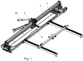
Figure 1 shows a perspective view of an exemplary embodiment of the monoguide manual cutter according to the invention. -
Figures 2 and3 show respective partial elevation views of the cutter with the tool holder in two angular positions in which the roller and the blank holder can be observed respectively in an operative position. -
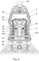
Figure 4 shows a profile view of the guide, the carriage and tool holder selected by a vertical plane. -
Figure 5 shows a cross section of an exemplary embodiment of the cutter guide, and below said guide the cutting roller. In this figure, the user's line of sight of the roller has been marked, without interference, due to the configuration of the guide. -
Figure 6 shows a cross section of the carriage mounted on the guide. -
Figure 7 shows a perspective view of the carriage, with the cover vertically cross-sectioned by a longitudinal median plane, allowing observation of the rolling means mounted thereon. - In the exemplary embodiment shown in
Figure 1 , the monoguide manual cutter comprises a base (1) for supporting the ceramic parts to be cut, a guide (2) arranged longitudinally above the base (1), a carriage (3) that can be moved along the aforementioned guide (2) and a tool holder (4) mounted on the carriage (3) able to rotate with respect to an axis perpendicular to the guide (2). - The aforementioned tool holder (4) has a drive handle (42) and, as shown in
figures 2 and3 , a roller (43) for marking a cutting line on a ceramic part (not shown) arranged on the base (1) and a blank holder (44) for subsequently breaking said ceramic part along the cutting line. The roller (43) and the blank holder (44) are mounted on the tool holder (4) by means of two rotation axes (45, 46). - The handle (42) allows the tool holder (4) to be rotated with respect to the axis of rotation (41) that connects the same to the carriage (3) to press the roller (43) against a ceramic part positioned on the base (1) and move the tool holder along the guide (2) marking a longitudinal cutting line on said ceramic part.
- The handle (42) also allows the tool holder (4) to be rotated in the opposite direction to distance the roller (43) from the marked part and then press the blank holder (44), in the position shown in
figure 3 , against the previously marked ceramic part, causing it to break along the cutting line. - In
figures 4 to 6 the guide (2) of the aluminium extrusion cutter comprises a cross section with a narrow lower portion (21); and a wider upper portion (22). - In this specific embodiment the guide (2) has a general T-shaped configuration and comprises in the wider upper portion (22) lateral wings (23) and longitudinal tracks (24, 25) for supporting and moving rolling means of the carriage (3).
- As shown in
figure 5 , the configuration of the guide (2), which is narrow at the bottom, makes it easier for the operator to view the roller (43) when using the cutter, since the guide (2) does not interrupt the line of vision (L). - This feature of the guide (2), in addition to improving the user's comfort of use of the cutter, allows a greater precision to be achieved in the placement of the ceramic part in relation to the roller and therefore a greater precision in the cut.
- The longitudinal tracks of the aluminium guide (2) are made up of two steel rails (24) inserted under the wings (23) of said guide (2) and by two oblique planes (25) defined at the upper end of the guide (2) and laterally inclined in opposite directions.
- The rolling means of the carriage (3) on the guide (2) comprise rail bearings (31) facing the steel rails (24) of the guide (2) and self-adjusting bearings (32) provided with a plastic outer sleeve (33) and facing the oblique planes (24) of the
guide 2. - The incorporation of the aforementioned steel rails (24) in the guide (2) prevents the reaction forces, originated when pressing the roller (43) or the blank holder (44) against the ceramic part to be cut, and transmitted by the rail bearings (31) to the guide (2), from causing damage to the aluminium of said guide (2).
- For its part, as shown in
figure 7 , the self-adjusting bearings (32) are mounted on two rocker arms (34) provided with an elastic element for self-adjusting the force applied by said self-adjusting bearings (32) on the oblique planes (25) of the guide (2). Said elastic element also contributes to the absorption of possible irregularities in the oblique planes (25) of the guide (2). - The longitudinal tracks formed by the steel rails (24) and by the oblique planes (25), and the rail bearings (31) and the self-adjusting bearings (32) are arranged respectively in the upper portion of the guide (2) and in the upper portion of the carriage (3) and spaced from the narrow lower portion of the guide; all this with the purpose of not constituting an obstacle in the line of vision (L) of the roller (43) by the operator.
- The carriage (3) is made of cast aluminium and has an inverted U-shaped cross-section, with two lateral wings (35), which is open inferiorly, and arranged on the guide (2), embracing the same from above and laterally.
- Said carriage (3) has a protective cover (36) made of aluminium at the top, which is shown cross-sectioned in
figure 7 , and which covers the self-adjusting bearings (32) and the respective rocker arms (34). - As shown in
figure 2 , the tool holder (4), made of cast aluminium, has an enveloping annular cross-section, arranged around the carriage (3) and the guide (2), and is attached to the lateral wings (35) of the carriage (3) by means of two independent semi-axes (41a, 41b), which form the axis of rotation (41) of the tool holder (4) with respect to the carriage (3). - Said semi-axes (41a, 41b) are aligned and arranged perpendicularly to the guide (2) in a horizontal plane located between the upper and lower ends of said guide.
- The use of the aforementioned half-axes (41a, 41b) allows: the tool holder (4) to be moved on the guide (2), together with the carriage (3), without said half-axes (41a, 41b) interfering with the guide (2); the axis of rotation of the tool holder to be arranged in an elevated position, and the axis of rotation (46) of the blank holder (44) to be as close as possible to the axis of rotation (41) of the tool holder (4), in order to take advantage of the lever and exert a greater separation force with the blank holder (44) on the ceramic part.
- As shown in
Figures 2 and3 , the tool holder (4) comprises laterally, at the lower end opposite to the handle holder (42), extensions (47) oriented towards the rear area of the cutter taking as a reference the direction of advance of the tool holder during the marking of the ceramic part; said extensions (47) ending in a rear end (48) carrying the axis of rotation (45) of the roller (43) and distanced from the axis of rotation (41) of the tool holder (4). - Advantageously, the axis of rotation (46) of the blank holder (44) is arranged between the axis of rotation (45) of the roller (43) and the axis of rotation (41) of the tool holder (4), so that in the operative position of the blank holder (44), shown in
figure 3 , said axis of rotation (46) is arranged close to a vertical plane coinciding with the axis of rotation (41) of the tool holder (4), maximising the breaking force of the ceramic part applied to the handle (42) and transmitted by the blank holder (44) to the ceramic part. - Having sufficiently described the nature of the invention, in addition to a preferred exemplary embodiment, it is hereby stated for the relevant purposes that the materials, shape, size and layout of the described elements may be modified, provided that it does not imply altering the essential features of the invention claimed below.
Claims (11)
- A monoguide manual cutter, comprising: a base (1) for supporting the ceramic parts to be cut, a guide (2) arranged longitudinally above the base, a carriage (3) that can be moved along said guide (2) and a tool holder (4) mounted on the carriage (3) able to rotate with respect to an axis perpendicular to the guide (2) and having a drive handle (42), a roller (43) for marking a cutting line on the ceramic part and a blank holder (44) for breaking said ceramic part along the cutting line; characterised in that the aluminium extrusion guide (2) comprises a cross-section with a narrow lower portion (21); and a wider upper portion (22), comprising longitudinal tracks for supporting and linearly moving rolling means of the carriage (3).
- The monoguide manual cutter, according to claim 1, wherein the guide (2) has a cross-section with a general T-shaped configuration, with two lateral wings (23) at the wider upper portion (22).
- The monoguide manual cutter according to claim 2, wherein the longitudinal tracks of the guide (2) comprise two steel rails (24) inserted under the lateral wings (23) of said guide (2) and two respective oblique planes (25) defined at the upper end of the guide (2) and laterally inclined in opposite directions.
- The monoguide manual cutter according to claim 3, wherein the rolling means of the carriage (3) comprise rail bearings (31) facing the steel rails (24) of the guide (2) and self-adjusting bearings (32) provided with a plastic outer sleeve (33) and facing the oblique planes (24) of the guide 2.
- The monoguide manual cutter, according to claim 4, wherein the self-adjusting bearings (32) are mounted on respective rocker arms (34) provided with an elastic element for self-adjusting the force applied on the oblique planes (25) of the guide and for absorbing irregularities of the oblique planes (25) of the guide (2).
- The monoguide manual cutter, according to claim 1, wherein the carriage (3), made of cast aluminium, comprises an inverted U-shaped cross-section, with two lateral wings (35), which is open inferiorly, and arranged on the guide (2).
- The monoguide manual cutter according to claim 6, wherein the carriage (3) comprises an upper protective cover (36) made of aluminium.
- The monoguide manual cutter according to claim 1, wherein the tool holder (4), made of cast aluminium, has an annular cross-section arranged around the carriage (3) and the guide (2):
- The monoguide manual cutter, according to any preceding claim, wherein the axis of rotation (41) of the tool holder (4) comprises two independent semi-axes of rotation (41a, 41b) mounted on the lateral wings (35) of the carriage (3), perpendicular to the guide (2) and arranged in a horizontal plane located between the upper and lower ends of said guide (2).
- The monoguide manual cutter, according to claim 1, wherein the tool holder laterally comprises at its lower end two extensions (47) oriented towards the rear area of the cutter and ending in a rear end (48) carrying the axis of rotation (45) of the roller (43) and spaced from the axis of rotation (41) of the tool holder.
- The monoguide manual cutter, according to claim 10, wherein the axis of rotation (46) of the blank holder (44) is arranged between the axis of rotation (45) of the roller and the axis of rotation (41) of the tool holder, and that in the operative position of the blank holder (44) said axis of rotation (46) is arranged close to a vertical plane coinciding with the axis of rotation (41) of the tool holder (4).
Applications Claiming Priority (1)
| Application Number | Priority Date | Filing Date | Title |
|---|---|---|---|
| PCT/ES2023/070115 WO2024180266A1 (en) | 2023-03-01 | 2023-03-01 | Monoguide manual cutter |
Publications (2)
| Publication Number | Publication Date |
|---|---|
| EP4501570A1 true EP4501570A1 (en) | 2025-02-05 |
| EP4501570A4 EP4501570A4 (en) | 2026-01-21 |
Family
ID=92589162
Family Applications (1)
| Application Number | Title | Priority Date | Filing Date |
|---|---|---|---|
| EP23925119.2A Pending EP4501570A4 (en) | 2023-03-01 | 2023-03-01 | HAND CUTTER WITH SINGLE FEED |
Country Status (5)
| Country | Link |
|---|---|
| US (1) | US20250050540A1 (en) |
| EP (1) | EP4501570A4 (en) |
| CN (1) | CN119212841A (en) |
| CA (1) | CA3250976A1 (en) |
| WO (1) | WO2024180266A1 (en) |
Family Cites Families (11)
| Publication number | Priority date | Publication date | Assignee | Title |
|---|---|---|---|---|
| FR2294029A1 (en) * | 1974-12-13 | 1976-07-09 | Muller Alfred | Plate and tile cutting device for stone - has rollers in guide profiles acting as pivot and bearing axles for tool holder |
| ES1062584Y (en) | 2006-03-27 | 2006-10-01 | Boada Germans Sa | CERAMIC MANUAL CUTTER |
| KR100718971B1 (en) * | 2006-08-08 | 2007-05-16 | 홍순철 | Tile cutting machine |
| ES1067012Y (en) | 2007-10-17 | 2008-07-16 | Boada Germans Sa | CERAMIC MANUAL CUTTER |
| ES1069449Y (en) | 2009-01-09 | 2009-06-24 | Boada Germans Sa | CERAMIC MANUAL CUTTER |
| KR101483500B1 (en) * | 2013-02-18 | 2015-01-16 | 안성민 | Tile cutting apparatus |
| ES2545036B1 (en) * | 2014-02-07 | 2016-06-14 | Bellota Herramientas, S.A. | MODULAR MACHINE TO CUT CERAMIC PARTS |
| ES2677006B1 (en) * | 2017-01-26 | 2019-05-07 | Boada Germans Sa | DEVICE FOR SELF-REGULATION OF A CUTTER HEAD FOR MONO-GUIA CUTTERS |
| IT201700066629A1 (en) * | 2017-06-15 | 2018-12-15 | Raimondi Spa | CUTTING SYSTEM FOR SHEETS |
| CN111774428B (en) * | 2020-07-07 | 2021-06-29 | 福建祥鑫股份有限公司 | Preparation method of high-strength aluminum alloy hollow guide rail section bar |
| IT202100001775U1 (en) * | 2021-04-08 | 2022-10-08 | Valter Ambrogiani | MECHANISM WITH CAMS FOR ENGRAVING AND SPLITTING TILES |
-
2023
- 2023-03-01 WO PCT/ES2023/070115 patent/WO2024180266A1/en not_active Ceased
- 2023-03-01 CN CN202380037817.3A patent/CN119212841A/en active Pending
- 2023-03-01 EP EP23925119.2A patent/EP4501570A4/en active Pending
- 2023-03-01 CA CA3250976A patent/CA3250976A1/en active Pending
-
2024
- 2024-10-29 US US18/930,413 patent/US20250050540A1/en active Pending
Also Published As
| Publication number | Publication date |
|---|---|
| WO2024180266A1 (en) | 2024-09-06 |
| CN119212841A (en) | 2024-12-27 |
| CA3250976A1 (en) | 2025-07-10 |
| EP4501570A4 (en) | 2026-01-21 |
| US20250050540A1 (en) | 2025-02-13 |
Similar Documents
| Publication | Publication Date | Title |
|---|---|---|
| EP2206590A1 (en) | Manual ceramics cutter | |
| EP4501570A1 (en) | Monoguide manual cutter | |
| US20050076509A1 (en) | Hand-held compass saw | |
| US4517869A (en) | Saw table for a compass saw | |
| KR101522826B1 (en) | Cutting apparatus including secondary safety cover | |
| US4693403A (en) | Glass breaking tool | |
| CA1264420A (en) | Press tool with removable working parts under the press | |
| EP2969338B1 (en) | Power tool comprising a rail stop system | |
| CN210305932U (en) | Adjustable plate shearing machine | |
| JP5219704B2 (en) | Chip dresser device | |
| CN210548454U (en) | Support arrangement for hydraulic plate shearing machine | |
| KR20180000708U (en) | Saw Support Guide Apparatus for Hand Jigsaw Power Tool | |
| CN216912999U (en) | Metal chipping device with thin metal clamping function | |
| CN217166702U (en) | Sheet metal shearing device | |
| CN220348071U (en) | Small-size automatic cutting machine | |
| CN219170187U (en) | Profile cutting device for precise cutting | |
| KR102820258B1 (en) | All-weather weld bead remover with straight-line driving capability | |
| CN219704228U (en) | Precision positioning device of plate cutting machine for metal processing | |
| EP3034218B1 (en) | Machining unit | |
| CN214185450U (en) | Feeding mechanism of a hydraulic shearing machine | |
| WO2014131929A1 (en) | Ambidextrous single-point breaking system for ceramic-cutting machines | |
| DE102008015478A1 (en) | Hand machine tool with fastening device | |
| CN210731197U (en) | Round steel cutting machine capable of improving cutting precision | |
| CN214517894U (en) | An automatic positioning steel plate punching and shearing machine | |
| CN107914037B (en) | Steel grating shearing machine |
Legal Events
| Date | Code | Title | Description |
|---|---|---|---|
| STAA | Information on the status of an ep patent application or granted ep patent |
Free format text: STATUS: THE INTERNATIONAL PUBLICATION HAS BEEN MADE |
|
| PUAI | Public reference made under article 153(3) epc to a published international application that has entered the european phase |
Free format text: ORIGINAL CODE: 0009012 |
|
| STAA | Information on the status of an ep patent application or granted ep patent |
Free format text: STATUS: REQUEST FOR EXAMINATION WAS MADE |
|
| 17P | Request for examination filed |
Effective date: 20241029 |
|
| AK | Designated contracting states |
Kind code of ref document: A1 Designated state(s): AL AT BE BG CH CY CZ DE DK EE ES FI FR GB GR HR HU IE IS IT LI LT LU LV MC ME MK MT NL NO PL PT RO RS SE SI SK SM TR |
|
| A4 | Supplementary search report drawn up and despatched |
Effective date: 20251222 |
|
| RIC1 | Information provided on ipc code assigned before grant |
Ipc: B28D 1/22 20060101AFI20251216BHEP |
|
| RAP3 | Party data changed (applicant data changed or rights of an application transferred) |
Owner name: RUBI TOOLS GROUP, S.A. |