EP4501513A1 - Narrow gap gas-shielded arc welding method and welding apparatus for narrow gap gas-shielded arc welding - Google Patents
Narrow gap gas-shielded arc welding method and welding apparatus for narrow gap gas-shielded arc welding Download PDFInfo
- Publication number
- EP4501513A1 EP4501513A1 EP23779056.3A EP23779056A EP4501513A1 EP 4501513 A1 EP4501513 A1 EP 4501513A1 EP 23779056 A EP23779056 A EP 23779056A EP 4501513 A1 EP4501513 A1 EP 4501513A1
- Authority
- EP
- European Patent Office
- Prior art keywords
- electrode
- welding
- electrodes
- range
- setting
- Prior art date
- Legal status (The legal status is an assumption and is not a legal conclusion. Google has not performed a legal analysis and makes no representation as to the accuracy of the status listed.)
- Pending
Links
Images



Classifications
-
- B—PERFORMING OPERATIONS; TRANSPORTING
- B23—MACHINE TOOLS; METAL-WORKING NOT OTHERWISE PROVIDED FOR
- B23K—SOLDERING OR UNSOLDERING; WELDING; CLADDING OR PLATING BY SOLDERING OR WELDING; CUTTING BY APPLYING HEAT LOCALLY, e.g. FLAME CUTTING; WORKING BY LASER BEAM
- B23K9/00—Arc welding or cutting
- B23K9/16—Arc welding or cutting making use of shielding gas
- B23K9/173—Arc welding or cutting making use of shielding gas and of a consumable electrode
-
- B—PERFORMING OPERATIONS; TRANSPORTING
- B23—MACHINE TOOLS; METAL-WORKING NOT OTHERWISE PROVIDED FOR
- B23K—SOLDERING OR UNSOLDERING; WELDING; CLADDING OR PLATING BY SOLDERING OR WELDING; CUTTING BY APPLYING HEAT LOCALLY, e.g. FLAME CUTTING; WORKING BY LASER BEAM
- B23K9/00—Arc welding or cutting
-
- B—PERFORMING OPERATIONS; TRANSPORTING
- B23—MACHINE TOOLS; METAL-WORKING NOT OTHERWISE PROVIDED FOR
- B23K—SOLDERING OR UNSOLDERING; WELDING; CLADDING OR PLATING BY SOLDERING OR WELDING; CUTTING BY APPLYING HEAT LOCALLY, e.g. FLAME CUTTING; WORKING BY LASER BEAM
- B23K9/00—Arc welding or cutting
- B23K9/02—Seam welding; Backing means; Inserts
- B23K9/0213—Narrow gap welding
-
- B—PERFORMING OPERATIONS; TRANSPORTING
- B23—MACHINE TOOLS; METAL-WORKING NOT OTHERWISE PROVIDED FOR
- B23K—SOLDERING OR UNSOLDERING; WELDING; CLADDING OR PLATING BY SOLDERING OR WELDING; CUTTING BY APPLYING HEAT LOCALLY, e.g. FLAME CUTTING; WORKING BY LASER BEAM
- B23K9/00—Arc welding or cutting
- B23K9/02—Seam welding; Backing means; Inserts
- B23K9/0216—Seam profiling, e.g. weaving, multilayer
-
- B—PERFORMING OPERATIONS; TRANSPORTING
- B23—MACHINE TOOLS; METAL-WORKING NOT OTHERWISE PROVIDED FOR
- B23K—SOLDERING OR UNSOLDERING; WELDING; CLADDING OR PLATING BY SOLDERING OR WELDING; CUTTING BY APPLYING HEAT LOCALLY, e.g. FLAME CUTTING; WORKING BY LASER BEAM
- B23K9/00—Arc welding or cutting
- B23K9/02—Seam welding; Backing means; Inserts
- B23K9/025—Seam welding; Backing means; Inserts for rectilinear seams
-
- B—PERFORMING OPERATIONS; TRANSPORTING
- B23—MACHINE TOOLS; METAL-WORKING NOT OTHERWISE PROVIDED FOR
- B23K—SOLDERING OR UNSOLDERING; WELDING; CLADDING OR PLATING BY SOLDERING OR WELDING; CUTTING BY APPLYING HEAT LOCALLY, e.g. FLAME CUTTING; WORKING BY LASER BEAM
- B23K9/00—Arc welding or cutting
- B23K9/16—Arc welding or cutting making use of shielding gas
- B23K9/173—Arc welding or cutting making use of shielding gas and of a consumable electrode
- B23K9/1735—Arc welding or cutting making use of shielding gas and of a consumable electrode making use of several electrodes
-
- B—PERFORMING OPERATIONS; TRANSPORTING
- B23—MACHINE TOOLS; METAL-WORKING NOT OTHERWISE PROVIDED FOR
- B23K—SOLDERING OR UNSOLDERING; WELDING; CLADDING OR PLATING BY SOLDERING OR WELDING; CUTTING BY APPLYING HEAT LOCALLY, e.g. FLAME CUTTING; WORKING BY LASER BEAM
- B23K9/00—Arc welding or cutting
- B23K9/18—Submerged-arc welding
- B23K9/186—Submerged-arc welding making use of a consumable electrodes
- B23K9/188—Submerged-arc welding making use of a consumable electrodes making use of several electrodes
-
- B—PERFORMING OPERATIONS; TRANSPORTING
- B23—MACHINE TOOLS; METAL-WORKING NOT OTHERWISE PROVIDED FOR
- B23K—SOLDERING OR UNSOLDERING; WELDING; CLADDING OR PLATING BY SOLDERING OR WELDING; CUTTING BY APPLYING HEAT LOCALLY, e.g. FLAME CUTTING; WORKING BY LASER BEAM
- B23K9/00—Arc welding or cutting
- B23K9/24—Features related to electrodes
- B23K9/28—Supporting devices for electrodes
- B23K9/29—Supporting devices adapted for making use of shielding means
- B23K9/291—Supporting devices adapted for making use of shielding means the shielding means being a gas
- B23K9/295—Supporting devices adapted for making use of shielding means the shielding means being a gas using consumable wire electrodes
-
- B—PERFORMING OPERATIONS; TRANSPORTING
- B23—MACHINE TOOLS; METAL-WORKING NOT OTHERWISE PROVIDED FOR
- B23K—SOLDERING OR UNSOLDERING; WELDING; CLADDING OR PLATING BY SOLDERING OR WELDING; CUTTING BY APPLYING HEAT LOCALLY, e.g. FLAME CUTTING; WORKING BY LASER BEAM
- B23K2101/00—Articles made by soldering, welding or cutting
- B23K2101/18—Sheet panels
-
- B—PERFORMING OPERATIONS; TRANSPORTING
- B23—MACHINE TOOLS; METAL-WORKING NOT OTHERWISE PROVIDED FOR
- B23K—SOLDERING OR UNSOLDERING; WELDING; CLADDING OR PLATING BY SOLDERING OR WELDING; CUTTING BY APPLYING HEAT LOCALLY, e.g. FLAME CUTTING; WORKING BY LASER BEAM
- B23K2103/00—Materials to be soldered, welded or cut
- B23K2103/02—Iron or ferrous alloys
- B23K2103/04—Steel or steel alloys
Definitions
- the present invention relates to a gas-shielded arc welding method and to a narrow-gap gas-shielded arc welding method and a welding apparatus for performing narrow-gap gas-shielded arc welding on thick steel plates.
- narrow gap refers to a groove having an angle of 25° or less and where a minimum gap of the groove between thick steel plates as members to be welded is 50% or less of the thickness of the thick steel plate.
- x to y representing a range of numerical values indicates x or more and y or less, that is, both x and y are inclusive.
- Gas-shielded arc welding which is used to weld steel materials, is widely used in the manufacturing fields of automobiles, construction, bridges, and electrical devices, for example.
- gas-shielded arc welding may be considered, in which a groove with a gap that is smaller than the thickness of each of the steel plates is subjected to multi-layer welding by a gas-shielded arc welding method.
- the narrow-gap gas-shielded arc welding requires less deposited amount compared with ordinary gas-shielded arc welding, and thus is expected to achieve high welding efficiency and energy saving, and further reduce the cost of the welding.
- Multi-electrode welding can increase the amount of deposited metal for filling in a groove, i.e., the amount of metal resulting from melted welding wire and adhering to the inner walls of the groove, by the number of electrodes used, achieving welding efficiency higher than that of single-electrode welding. Therefore, such welding is an effective means to contribute to welding efficiency.
- Patent Literature 1 describes a narrow-gap gas-shielded arc welding method for joining thick steel plates by narrow-gap multi-layer welding.
- the technology described in Patent Literature 1 includes using multi-electrode welding with two or more electrodes for the first-layer welding, arranging a first electrode and a second electrode at positions along predetermined parallel weld lines, controlling the distance between the distal ends of respective welding wires of the first electrode and the second electrode to be in the range of 5 to 16 mm, and controlling the angle between a straight line, which connects the distal ends of the respective welding wires of the first electrode and the second electrode, and a direction perpendicular to the weld lines to be in the range of 45° or less, thereby achieving a melt depth of 1.5 mm or more at the bottom of each thick steel plate in the direction perpendicular to the weld lines. Accordingly, even when beveling such as gas cutting or plasma arc cutting, has been applied, it is possible to achieve the effect of increasing the welding efficiency without the
- Patent Literature 1 JP-2015-223605A
- An object of the present invention is to provide a narrow-gap gas-shielded arc welding technology that, when performing multi-electrode welding on thick steel plates using three or more electrodes, can achieve excellent welding quality and high welding efficiency without requiring treatment for groove surfaces, even when low-cost beveling has been applied.
- Examples of low-cost beveling include gas cutting and plasma arc cutting.
- excellent welding quality refers to a state in which the occurrence of defects such as poor fusion and defects such as hot cracks that would occur in the center of a weld metal is prevented.
- the inventors have conducted intensive studies on the cause of hot cracks that would occur in a weld metal in multi-electrode welding with three or more electrodes. As a result, the inventors have found that when the distance between adjacent electrodes selected from a second electrode and subsequent electrodes falls out of an appropriate range, a welding defect leading to a hot crack occurs in the center of a weld metal, and that a weld joint with a high-quality bead, that is, a high-quality weld metal is obtained by adjusting the distance between the adjacent electrodes selected from the second electrode and subsequent electrodes to be in an appropriate range.
- the inventors have also found that when performing multi-electrode welding with three or more electrodes as multi-layer welding, by arranging a first electrode and a second electrode at positions along predetermined parallel weld lines, setting one of the first electrode and the second electrode to positive polarity and setting the other electrode to reverse polarity, appropriately adjusting the relative positions of the first electrode and the second electrode during the welding process, and setting the diameter of the welding wire used for each electrode of the multiple electrodes to a small diameter in the range of 1.0 to 1.6 mm, a total amount of deposited metal per unit time by all electrodes becomes 200 g/min or more, and a melt depth p at the bottom of each thick steel plate becomes 1.5 mm or more. Accordingly, the inventors have found it possible to perform multi-layer welding on thick steel plates with high welding efficiency.
- the narrow-gap gas-shielded arc welding method and the welding apparatus for performing narrow-gap gas-shielded arc welding according to the present invention can achieve excellent welding quality and high welding efficiency without performing treatment for the groove surface, even when low-cost beveling has been applied. In particular, defects such as poor fusion, and defects such as hot cracks that would occur in the center of a weld metal can be prevented. Thus, since multi-electrode welding with three or more electrodes is applicable to all layers for multi-layer welding, the welding process efficiency improves.
- the production of a weld joint by the technology according to the present invention can significantly reduce the welding process cost compared to the production of conventional weld joints, and thus is industrially advantageous.
- the present invention is very useful to be applied to a welding process for general structures, such as for construction, bridges, and shipbuilding.
- reference sign 1 denotes a thick steel plate
- reference sign 2 denotes the surfaces of a groove between the thick steel plates
- symbol ⁇ denotes the groove angle
- reference sign G denotes the gap at the groove bottom
- reference sign t denotes the thickness of each plate.
- the surface having a smaller gap in the thickness direction of a plate corresponds to the bottom.
- the present embodiment is a narrow-gap gas-shielded arc welding method for joining thick steel plates 1, 1 that have a groove angle ⁇ of 25° or less and a gap G at the groove bottom in the range of 7 to 18 mm and each have a thickness t of 22 mm or more, by narrow-gap multi-layer welding.
- the term "thick steel plates” herein includes not only steel plates but also thick-walled materials, thick steel materials, and so on.
- Thickness t of thick steel plate 1 22 mm or more
- the thickness t of the thick steel plate 1 is 22 mm or more. This is because when the thickness of the thick steel plates 1 is less than 22 mm, a conventional single bevel groove has a smaller cross-sectional area than the target groove of the present invention by increasing the groove angle to reduce the groove gap. Therefore, the conventional single bevel groove may require a smaller amount of weld metal, resulting in a higher welding efficiency.
- the plate thickness of steel structures is about 200 mm at maximum.
- the preferable upper limit of the thickness t of the thick steel plate 1 is 200 mm.
- the present embodiment is applicable to various thick steel plates ranging from soft steel plates to 980 MPa grade high-tension steel plates. When the present embodiment is applied to the welding of a 590 MPa grade high-tension, thick steel plates, it is possible to perform the welding without preheating the plates.
- the groove used in the present embodiment is a square groove or a single V groove.
- the groove angle ⁇ (°) is in the range of (0.5 ⁇ t/20) to (2.0 ⁇ t/20). More preferably, it is set in the range of (0.8 ⁇ t/20) to (1.8 ⁇ t/20). Further preferably, the upper limit of the groove angle ⁇ is set to 10°.
- the conventional welding method is applicable to welding using a groove angle ⁇ exceeding 25°. Therefore, in the present embodiment, the upper limit of the groove angle ⁇ is set to 25°.
- the gap G at the groove bottom is set in the range of 7 to 18 mm. With such a range, it would be difficult to perform welding with the conventional welding method, and thus, it is expected that applying the present embodiment can further improve the welding efficiency.
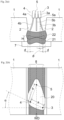
- Fig. 2 illustrates the procedures of a welding process with three electrodes according to the present embodiment.
- Fig. 2(a) is a front view
- Fig. 2(b) is a top view.
- Fig. 3 is a view of an example of a cross-section of a weld joint subjected to multi-layer welding with three electrodes.
- each layer following first-layer welding 21 and second-layer welding 22 is welded by multi-electrode welding with three or more electrodes, using the narrow groove with the shape described above.
- the welding is performed to obtain a weld joint with high welding efficiency so as to reduce the occurrence of defects such as poor fusion, and hot cracks, particularly hot cracks that would occur in the center of a weld metal.
- the beveling for thick steel plates uses working including gas cutting, plasma arc cutting, or laser cutting.
- machining is not excluded.
- the melt depth (p shown in Fig. 3 described below) required for each groove surface in the narrow-gap gas-shielded arc welding is mainly determined by the surface quality of the groove surface 2, particularly the depth of a recess portion and the cleanliness.
- the finished cut plane greatly varies greatly depending on the gas flow rate and burner selected for gas cutting, except when using special steel, stainless steel or the like.
- the depth of the recess portion on the groove surface is about 0.2 mm or less when the gas flow rate and the burner are properly adjusted.
- the depth of the recess portion may exceed 1 mm.
- the groove surface is directly subjected to welding without undergoing any treatment in the case of a general structure and so on.
- the melt depth p at the bottom (thick steel plate) of the groove is set to 1.5 mm or more. Preferably, it is 2.0 mm or more. However, when the melt depth p is more than 4 mm, an undercut is formed at the upper portion of the weld bead on the groove surfaces 2, which may cause a welding defect. Therefore, the melt depth is preferably set to 4 mm or less.
- the melt depth p at the bottom (thick steel plate) of the groove it is essential to set the melt depth p at the bottom (thick steel plate) of the groove to 1.5 mm or more. In order to achieve such a melt depth p with high welding efficiency, it is crucial to appropriately control the welding conditions of the gas-shielded arc welding.
- multi-electrode welding with three or more electrodes is performed as multi-layer welding from the viewpoint of improving hot cracking resistance, particularly, reducing hot cracks that would occur in a weld metal.
- four or less electrodes are used from the viewpoint of improving welding efficiency.
- the electrodes are numbered from a leading electrode in the welding direction WD, and subsequent electrodes are numbered in ascending order in a similar manner.
- Fig. 2 illustrates process procedures when multi-layer welding is performed with three electrodes.
- the first electrode 3 and the second electrode 4 are preferably arranged along respective weld lines 8 that are parallel to each other and are close to different groove surfaces 2.
- first electrode 3 and the second electrode 4 are set to the same polarity (for example, when both the first electrode 3 and the second electrode 4 are set to wire plus), their arcs are directed inward due to the attracting electromagnetic forces, so that heat is concentrated in the center of the groove. Thus, each groove surface 2 is not melted sufficiently.
- one of the first electrode 3 and the second electrode 4 is set to wire minus (positive polarity) and the other electrode is set to wire plus (reverse polarity) and the arrangement of the first electrode 3 and the second electrode 4 is appropriately controlled, the magnetic field resulting from their welding currents produces strong outward electromagnetic forces, so that their arcs repel each other. Consequently, a sufficient melt depth p of each groove surface can be obtained.
- one of the welding wires fed from the power feed tips at the distal ends of the respective welding torches of the first electrode and the second electrode is set to wire minus (positive polarity), and the other welding wire is set to wire plus (reverse polarity).
- the distance a (hereinafter also simply referred to as the "first electrode-second electrode distance,” see Fig. 2(b) ) between the distal ends of welding wires 3b and 4b fed from power feed tips 3a and 4a at the distal ends of the respective welding torches of the first electrode 3 and the second electrode 4 is set to be in the range of 5 to 16 mm.
- the term "distance between the distal ends of the welding wires” herein refers to the distance between the centers of the distal ends of the welding wires of the respective electrodes.
- the first electrode-second electrode distance a is less than 5 mm, a current (electrons) flows between the electrodes, with the result that the amount of heat of arcs themselves decreases, and the groove surface 2 is not melted sufficiently.
- the first electrode-second electrode distance a is more than 16 mm, outward electromagnetic forces between the electrodes decrease in inverse proportion to the distance. Therefore, it is impossible to obtain repulsive forces of arcs that can overcome inward electromagnetic forces resulting from currents flowing through the groove surface 2. Thus, both arcs are directed inward, causing heat to be concentrated in the center of the groove. Consequently, the groove surface 2 is not melted sufficiently.
- the problem to be solved is to reduce welding defects due to sputter adhering to the groove surfaces 2.
- the first electrode 3 and the second electrode 4 along the predetermined parallel weld lines 8 and 8, and setting one of the first electrode 3 and the second electrode 4 to positive polarity while setting the other electrode to reverse polarity, and further adjusting the first electrode-second electrode distance a to the range of 5 to 16 mm, sputter is caused to be absorbed into the respective molten metals. This can reduce the adhesion of sputter to the groove surfaces 2, and thus a high-quality weld can be obtained.
- the distance a between the distal ends of the welding wires fed from the power feed tips provided at the distal ends of the respective welding torches of the first electrode 3 and the second electrode 4 is adjusted to be in the range of 5 to 16 mm.
- the groove surface 2 is melted using the repulsion of arcs.
- the angle ⁇ (hereinafter also simply referred to as the "first electrode-second electrode arrangement angle,” see Fig. 2(b) ) between a straight line connecting the distal ends of the respective welding wires of the first electrode and the second electrode, and a direction perpendicular to the weld lines is more than 60°, sufficient repulsive forces of arc cannot be obtained, so that the groove surface 2 cannot be sufficiently melted.
- the first electrode-second electrode arrangement angle ⁇ is limited to the range of 60° or less. More preferably, the first electrode-second electrode arrangement angle ⁇ is 45° or less. Note that the first electrode-second electrode arrangement angle ⁇ may be 0°.
- each welding wire 1.0 to 1.6 mm
- a typical welding wire used for gas-shielded arc welding is produced to have a diameter within the range of 0.6 to 2.0 mm. Provided that welding is performed with the same amount of welding current, a higher deposition rate is obtained by the Joule heat as the wire diameter D is smaller. Therefore, it is preferable to select a relatively small wire diameter D to achieve a highly efficient welding process. On the other hand, when the wire diameter D is too small, the welding wire becomes soft due to the Joule heat, resulting in unstable welding. In view of such points, the diameter D of each welding wire is set in the range of 1.0 to 1.6 mm. Preferably, the diameter D of each welding wire is set in the range of 1.2 to 1.4 mm. In the present embodiment, the same type of welding wire is used for all of the multiple electrodes.
- the welding wire used in the present embodiment is preferably selected from various steel wires having a diameter D in the above range and corresponding to the steel grade of the thick steel plates 1 as the materials to be welded, for example, various steel wires defined by JIS Z 3312.
- welding is performed by using the welding wires described above and setting the total amount of deposited metal per unit time by all electrodes to 200 g/min or more to perform welding with higher efficiency than the conventional method.
- the amount of deposited metal per unit time is less than 200 g/min, welding requires a longer time.
- the amount of deposited metal per unit time is about 60 to 160 g/min, though it varies with the wire diameter D and the amount of welding current.
- the deposition rate according to the present embodiment is about twice that of conventional single-electrode welding.
- the heat source of arcs generated from the third electrode 5 is essential to control the heat source of arcs generated from the third electrode 5 onward within an optimal range.
- the distance between adjacent electrodes selected from the second electrode 4 and subsequent electrodes is too small, the input heat is concentrated in the central portion of a weld metal, increasing the likelihood of hot cracks occurring during the solidification of the metal.
- the distance between adjacent electrodes selected from the second electrode 4 and subsequent electrodes is too large, the interaction between the electrodes becomes too small, and thus the molten pool 20 becomes too long in the longitudinal direction or separated from each other, so that hot cracks are likely to occur during the solidification of the molten pool 20.
- the distance between the adjacent electrodes i.e., electrode-electrode distance
- the distance between the adjacent electrodes is limited to the range of 10 to 100 mm to prevent hot cracks.
- the distance is in the range of 20 to 80 mm.
- the welding conditions described above are the basic welding conditions of the present embodiment. By performing welding under such conditions, it is possible to obtain a weld joint in which hot cracks in a weld metal portion are prevented, even when multi-electrode welding is performed with three or more electrodes for each layer, and which has a melt depth p of 1.5 mm or more at the bottom of the thick steel plate in the direction perpendicular to the weld lines.
- An arc is directional and tends to be directed in the direction of the distal end of an electrode (a welding wire) is pointing.
- the direction in which the distal end of the electrode faces greatly varies depending on the feed angle of the welding wire fed from the power feed tip at the distal end of the welding torch.
- the outward direction that is, in a direction toward the groove surface 2
- the inward direction is referred to as a "negative direction.”
- the feed angle ⁇ of each of the welding wires 3b and 4b fed from the power feed tips 3a and 4a at the distal ends of the respective welding torches with respect to the groove bottom is less than 0° with respect to the perpendicular line, that is, in a state where the distal ends of the welding wires 3b and 4b of the first electrode 3 and the second electrode 4, respectively, are closer to each other, a current flows through a path with lower resistance.
- the feed angle ⁇ of each of the welding wires 3b and 4b of the first electrode 3 and the second electrode 4, respectively, with respect to the groove at the bottom is preferably in the range of 0 to 15° with respect to the perpendicular line. More preferably, the feed angle ⁇ is in the range of 5 to 12°.
- the feed angle ⁇ of each of the welding wires 3b and 4b of the first electrode 3 and the second electrode 4, respectively, with respect to the groove at the bottom is the same as the tilt of each of the power feed tips 3a and 4a, particularly each of the distal ends of the power feed tips.
- it is possible to control the feed angle of each welding wire by controlling the tilt of the distal end of each power feed tip.
- the distance d between each of the side end portions at the distal ends of the welding wires 3b and 4b and each of the groove surfaces 2 of the thick steel plates 1 is preferably set in the range of 0.5 to 3.0 mm.
- the distance d is set in the range of 0.5 to 2.0 mm, and more preferably in the range of 0.5 to 1.0 mm.
- the expression “side end portions at the distal ends of the welding wires” refers to the side end portions near the groove surfaces 2 of the respective thick steel plates 1 to be melted with the electrodes 3 and 4.
- each of the power feed tips 3a and 4a with a curved distal end is used.
- the curvature radius R of the respective welding wires 3b and 4b is less than 150 mm, the feed resistance of the wire increases. Thus, it is impossible to stably feed the welding wires 3b and 4b, and it is thus difficult to maintain arcs.
- the curvature radius R of the respective welding wires 3b and 4b is more than 300 mm, there is no effect of reducing the feed resistance of the wire with the distal ends of the power feed tips 3a and 4a being curved. Thus, it is still impossible to stably feed the welding wires 3b and 4b, and thus difficult to maintain arcs.
- the curvature radius R of the respective welding wires 3b and 4b fed to the power feed tips 3a and 4a of the first electrode 3 and the second electrode 4 is preferably set in the range of 150 to 300 mm. More preferably, the curvature radius R is set in the range of 175 to 275 mm.
- the third electrode and subsequent electrodes arranged in the center of the groove behind the first electrode and the second electrode
- the polarity of each of the third electrode 5 and subsequent electrodes is not limited to a particular polarity, and may be either wire minus (positive polarity) or wire plus (reverse polarity).
- the term "center of the groove” may include 10% of the gap G of the groove on both sides of the center line 81 of the groove, when viewed from above.
- a shielding gas a mixed gas containing 60 volume% or more CO 2 gas
- the oxygen content in a weld metal is significantly influenced by the ingredient composition of a shielding gas.
- a mixed gas containing 60 volume% CO 2 or more and the balance being an inert gas such as Ar as a shielding gas used for gas-shielded arc welding.
- the content of CO 2 gas of 100 volume% is more preferable.
- the welding current may be set in the range of 280 to 360 A, the welding voltage, which rises with the current, in the range of 32 to 37 V, the welding rate to 30 to 90 cm/min, the wire extension length to 15 to 30 mm, and the welding heat input per path to 10 to 50 kJ/cm.
- the present apparatus a welding apparatus that is suitably used in the present embodiment (hereinafter referred to as "the present apparatus") will be described.
- the present apparatus is a welding apparatus for narrow-gap gas-shielded arc welding that joins thick steel plates each having a thickness of 22 mm or more by narrow-gap multi-layer welding, using a multi-electrode gas-shielded welding method with three or more electrodes according to the foregoing embodiment.
- Fig. 4 shows a schematic view of the configuration of the present apparatus when four electrodes are used.
- Fig. 4(a) is a perspective view
- Fig. 4(b) is a front view
- Fig. 4(c) is a top view.
- a welding apparatus 100 includes a welding base or a welding carriage (not shown), a plurality of electrodes 3 to 6 including three or more electrodes, a plurality of welding power supplies 9 to 12 that respectively feed welding power to the plurality of electrodes 3 to 6, power feed tips 3a to 6a provided at the distal ends of respective welding torches of the plurality of electrodes 3 to 6, a plurality of welding wire feeding means (not shown) for respectively feeding welding wires 3b to 6b to the plurality of electrodes 3 to 6, and a shielding gas feeding means (not shown) for feeding a shielding gas.
- the first electrode 3 and the second electrode 4 are connected such that one of the first electrode 3 and the second electrode 4 is set to wire minus (positive polarity) and the other electrode is set to wire plus (reverse polarity).
- the power feed tips 3a to 6a are each configured to feed the welding wires 3b to 6b, each having a diameter in the range of 1.0 to 1.6 mm.
- the first electrode 3 and the second electrode 4 are arranged at positions along the predetermined parallel weld lines 8 and 8, respectively, and are also arranged such that the distance a between the distal ends of the welding wires 3b and 4b fed from the power feed tips 3a and 4a provided at the distal ends of the welding torches of the respective electrodes is in the range of 5 to 16 mm, as the distance between the first electrode 3 and the second electrode 4.
- first electrode 3 and the second electrode 4 are arranged such that the angle ⁇ between a straight line, which connects the distal ends of the welding wires 3b and 4b fed from the power feed tips 3a and 4a provided at the distal ends of the respective welding torches of the first electrode 3 and the second electrode 4, and the direction perpendicular to the weld lines 8 is 60° or less.
- the third electrode 5 and subsequent electrodes are provided such that the distance between adjacent electrodes selected from the second electrode 4 and subsequent electrodes is in the range of 10 to 100 mm.
- the subsequent electrode that is, the third electrode 5 is arranged such that the distance b between the second electrode 4 and the third electrode 5 is in the range of 10 to 100 mm as the distance between the distal ends of the welding wires 4b and 5b fed from the welding tips 4a and 5a provided at the distal ends of the respective welding torches of the electrodes 4 and 5.
- a fourth electrode 6 is provided such that the distance c between the third electrode 5 and the fourth electrode 6 is in the range of 10 to 100 mm.
- Fig. 4 shows a case where four electrodes, specifically the first electrode 3, the second electrode 4, the third electrode 5, and the fourth electrode 6 are used.
- the welding power supplies 9, 10, 11, and 12 are connected to the respective electrodes to feed welding power thereto.
- the first electrode 3 and the second electrode 4 are connected such that one of them is set to wire minus (positive polarity), and the other is set to wire plus (reverse polarity).
- the polarity of each of the third electrode 5 and subsequent electrodes is not limited to a particular polarity and may be set to either positive polarity or reverse polarity.
- the power feed tips 3a, 4a, 5a, and 6a are provided at the distal ends of the respective welding torches of the electrodes 3, 4, 5, and 6, and welding currents are fed to the welding wires 3b, 4b, 5b, and 6b through the power feed tips 3a, 4a, 5a, and 6a, respectively.
- the welding apparatus 100 includes the welding wire feeding means (not shown) for feeding the welding wires 3b, 4b, 5b, and 6b to the respective welding torches (electrodes), and the shielding gas feeding means (not shown).
- the welding apparatus 100 may also include a regularly used moving means (not shown) capable of moving the electrodes or the welding base at a predetermined speed. For both the welding wire feeding means and the shielding gas feeding means, regularly used means may be suitably used.
- each of the power feed tips 3a and 4a provided at the distal ends of the respective welding torches of the first electrode 3 and the second electrode 4 is preferably inclined outward at an angle in the range of 0 to 15° with respect to the perpendicular line at the distal end. This can stably increase the melt depth p of each groove surface 2 at the bottom.
- the welding wire feeding means are configured to be able to feed the first electrode 3 and the second electrode 4 with the welding wires 3b and 4b, respectively, that are curved to achieve a curvature radius R in the range of 150 to 300 mm, it is easy to allow the feed angle ⁇ of each of the welding wires 3b and 4b to be fed from the power feed tips 3a and 4a to be in the range of 0 to 15°.
- Fig. 4(c) shows only the distal end positions of the welding wires 3b, 4b, 5b, and 6b of the electrodes 3, 4, 5, and 6, and omits the other configurations.
- the third electrode 5 and subsequent electrodes are preferably arranged in the center of the groove behind the first electrode 3 and the second electrode 4 with respect to the welding direction WD. This can reduce the occurrence of hot cracks.
- center of the groove may include 10% of the gap G of the groove on both sides of the center line 81 of the groove, when viewed from above.
- the thick steel plates 1 having the groove shapes shown in Table 2 had a length of 500 mm in the welding direction WD.
- narrow-gap gas-shielded arc welding was performed thereon using welding wires corresponding to the steel types (grades) shown in Table 1 under the welding conditions shown in Tables 3 and 4 as the first-layer welding 21.
- multi-layer welding including the second-layer welding 22 and the welding of the following layer(s) was performed to obtain a narrow-gap gas-shielded arc weld joint with a weld length of 500 mm.
- the welding conditions for the second-layer welding 22 and the welding of the following layer(s) were the same the welding conditions as those for the first-layer welding 21.
- the third electrode 5 and subsequent electrode(s) were used, all of the electrodes were arranged in the center of the groove behind the first electrode 3 and the second electrode 4 in the welding direction WD.
- test results were indicated by "Excellent.”
- the test result is indicated by "Good.”
- the test result is indicated by "Poor.”
- Table 4 also shows the results.
Landscapes
- Engineering & Computer Science (AREA)
- Physics & Mathematics (AREA)
- Plasma & Fusion (AREA)
- Mechanical Engineering (AREA)
- Arc Welding In General (AREA)
Abstract
Description
- The present invention relates to a gas-shielded arc welding method and to a narrow-gap gas-shielded arc welding method and a welding apparatus for performing narrow-gap gas-shielded arc welding on thick steel plates. The term "narrow gap" as used herein refers to a groove having an angle of 25° or less and where a minimum gap of the groove between thick steel plates as members to be welded is 50% or less of the thickness of the thick steel plate. In this specification, the expression "x to y" representing a range of numerical values indicates x or more and y or less, that is, both x and y are inclusive.
- Gas-shielded arc welding, which is used to weld steel materials, is widely used in the manufacturing fields of automobiles, construction, bridges, and electrical devices, for example. In recent years, with increases in the size and thickness of steel structures, there has also been an increase in the deposited amount during welding in the production process, particularly during butt welding of steel materials. The time required for the welding has also increased. This has resulted in an increased cost of the process. Thus, applying narrow-gap gas-shielded arc welding may be considered, in which a groove with a gap that is smaller than the thickness of each of the steel plates is subjected to multi-layer welding by a gas-shielded arc welding method. The narrow-gap gas-shielded arc welding requires less deposited amount compared with ordinary gas-shielded arc welding, and thus is expected to achieve high welding efficiency and energy saving, and further reduce the cost of the welding.
- Further, a technology for performing such narrow-gap gas-shielded arc welding using multiple electrodes has been recently proposed. Multi-electrode welding can increase the amount of deposited metal for filling in a groove, i.e., the amount of metal resulting from melted welding wire and adhering to the inner walls of the groove, by the number of electrodes used, achieving welding efficiency higher than that of single-electrode welding. Therefore, such welding is an effective means to contribute to welding efficiency.
- For example,
Patent Literature 1 describes a narrow-gap gas-shielded arc welding method for joining thick steel plates by narrow-gap multi-layer welding. The technology described inPatent Literature 1 includes using multi-electrode welding with two or more electrodes for the first-layer welding, arranging a first electrode and a second electrode at positions along predetermined parallel weld lines, controlling the distance between the distal ends of respective welding wires of the first electrode and the second electrode to be in the range of 5 to 16 mm, and controlling the angle between a straight line, which connects the distal ends of the respective welding wires of the first electrode and the second electrode, and a direction perpendicular to the weld lines to be in the range of 45° or less, thereby achieving a melt depth of 1.5 mm or more at the bottom of each thick steel plate in the direction perpendicular to the weld lines. Accordingly, even when beveling such as gas cutting or plasma arc cutting, has been applied, it is possible to achieve the effect of increasing the welding efficiency without the occurrence of defects. - Patent Literature 1:
JP-2015-223605A - However, when multi-electrode welding is performed with three or more electrodes using the technology of
Patent Literature 1, there is a problem of causing hot cracks in the center of a weld metal. - An object of the present invention is to provide a narrow-gap gas-shielded arc welding technology that, when performing multi-electrode welding on thick steel plates using three or more electrodes, can achieve excellent welding quality and high welding efficiency without requiring treatment for groove surfaces, even when low-cost beveling has been applied. Examples of low-cost beveling include gas cutting and plasma arc cutting. Note that excellent welding quality refers to a state in which the occurrence of defects such as poor fusion and defects such as hot cracks that would occur in the center of a weld metal is prevented.
- To achieve the above object, the inventors have conducted intensive studies on the cause of hot cracks that would occur in a weld metal in multi-electrode welding with three or more electrodes. As a result, the inventors have found that when the distance between adjacent electrodes selected from a second electrode and subsequent electrodes falls out of an appropriate range, a welding defect leading to a hot crack occurs in the center of a weld metal, and that a weld joint with a high-quality bead, that is, a high-quality weld metal is obtained by adjusting the distance between the adjacent electrodes selected from the second electrode and subsequent electrodes to be in an appropriate range. The inventors have also found that when performing multi-electrode welding with three or more electrodes as multi-layer welding, by arranging a first electrode and a second electrode at positions along predetermined parallel weld lines, setting one of the first electrode and the second electrode to positive polarity and setting the other electrode to reverse polarity, appropriately adjusting the relative positions of the first electrode and the second electrode during the welding process, and setting the diameter of the welding wire used for each electrode of the multiple electrodes to a small diameter in the range of 1.0 to 1.6 mm, a total amount of deposited metal per unit time by all electrodes becomes 200 g/min or more, and a melt depth p at the bottom of each thick steel plate becomes 1.5 mm or more. Accordingly, the inventors have found it possible to perform multi-layer welding on thick steel plates with high welding efficiency.
- The present invention has been completed based on the above findings and with further studies. That is, the summary of the present invention is as follows.
- [1] A narrow-gap gas-shielded arc welding method for joining thick steel plates each having a thickness t of 22 mm or more and forming a groove angle θ of 25° or less and a gap G at a groove bottom in a range of 7 to 18 mm, using narrow-gap multi-layer welding, the method being characterized by including:
- performing multi-electrode welding with three or more electrodes as the multi-layer welding;
- arranging, among the multiple electrodes, a first electrode and a second electrode at positions along predetermined parallel weld lines;
- setting one of the first electrode and the second electrode to positive polarity, and setting the other to reverse polarity;
- setting a distance a between distal ends of welding wires fed from power feed tips provided at distal ends of respective welding torches of the first electrode and the second electrode to a range of 5 to 16 mm, and setting an angle α between a straight line that connects the distal ends of the respective welding wires of the first electrode and the second electrode and a direction perpendicular to the weld lines to a range of 60° or less;
- setting a diameter of the welding wire used for each electrode of the multiple electrodes to a range of 1.0 to 1.6 mm;
- setting a distance between adjacent electrodes selected from the second electrode and subsequent electrodes among the multiple electrodes to a range of 10 to 100 mm;
- optionally, setting a feed angle φ of each of the welding wires fed to the groove bottom from the respective power feed tips of the first electrode and the second electrode to a range of 0 to 15° with respect to a line perpendicular to the groove bottom;
- optionally, setting a distance d between each of side end portions at the distal ends of the respective welding wires fed from the first electrode and the second electrode and each of groove surfaces of the thick steel plates to a range of 0.5 to 3.0 mm; and
- setting a total amount of deposited metal per unit time by all electrodes to 200 g/min or more and setting a melt depth p at the bottom of each thick steel plate in the direction perpendicular to the weld lines to 1.5 mm or more.
- [2] The narrow-gap gas-shielded arc welding method according to [1], further including arranging a third electrode and subsequent electrodes in a center of the groove behind the first electrode and the second electrode.
- [3] The narrow-gap gas-shielded arc welding method according to [1] or [2], further including feeding welding wires, each curved to have a curvature radius in a range of 150 to 300 mm, to the respective power feed tips of the first electrode and the second electrode.
- [4] The narrow-gap gas-shielded arc welding method according to [1] or [2], further including using a mixed gas containing 60 volume% or more CO2 gas as a shielding gas for the multi-layer welding.
- [5] A welding apparatus for performing narrow-gap gas-shielded arc welding that performs narrow-gap multi-layer welding on thick steel plates, each having a thickness t of 22 mm or more and having a groove angle θ of 25° or less and a gap G at the groove bottom in a range of 7 to 18 mm, characterized by including a plurality of electrodes including three or more electrodes; a plurality of welding power supplies that supply welding power to the respective electrodes; power feed tips provided at distal ends of welding torches of the respective electrodes; a plurality of welding wire feeding means for feeding welding wires to the respective electrodes; shielding gas feeding means for feeding a shielding gas; and a welding base or a welding carriage,
- in which, among the plurality of electrodes,
- a first electrode and a second electrode are connected such that one of the first electrode and the second electrode is set to positive polarity and the other is set to reverse polarity;
- each power feed tip is configured to feed a welding wire in a range of 1.0 to 1.6 mm;
- the first electrode and the second electrode are arranged at positions along predetermined parallel weld lines, and are also arranged such that a distance therebetween is in a range of 5 to 16 mm as a distance a between distal ends of the welding wires fed from the power feed tips provided at the distal ends of the welding torches of the respective electrodes, and are further arranged such that an angle α between a straight line connecting the distal ends of the welding wires fed from the power feed tips provided at the distal ends of the respective welding torches of the first electrode and the second electrode and a direction perpendicular to the weld lines is 60° or less;
- a third electrode and subsequent electrodes are arranged such that a distance between adjacent electrodes selected from the second electrode and subsequent electrodes is in a range of 10 to 100 mm; and
- optionally, the power feed tips provided at the distal ends of the respective welding torches of the first electrode and the second electrode are each inclined at an angle in a range of 0 to 15° with respect to a perpendicular line at the distal ends.
- [6] The welding apparatus for performing narrow-gap gas-shielded arc welding according to [5], in which the third electrode and subsequent electrodes are arranged in the center of the groove behind the first electrode and the second electrode.
- [7] The welding apparatus for performing narrow-gap gas-shielded arc welding according to [5] or [6], in which the welding wire feeding means is configured to be able to feed welding wires each curved to have a curvature radius in a range of 150 to 300 mm.
- [8] The welding apparatus for performing narrow-gap gas-shielded arc welding according to [5] or [6], in which the shielding gas feeding means is configured to feed a mixed gas containing 60 volume% or more CO2 gas as a shielding gas.
- The narrow-gap gas-shielded arc welding method and the welding apparatus for performing narrow-gap gas-shielded arc welding according to the present invention can achieve excellent welding quality and high welding efficiency without performing treatment for the groove surface, even when low-cost beveling has been applied. In particular, defects such as poor fusion, and defects such as hot cracks that would occur in the center of a weld metal can be prevented. Thus, since multi-electrode welding with three or more electrodes is applicable to all layers for multi-layer welding, the welding process efficiency improves. The production of a weld joint by the technology according to the present invention can significantly reduce the welding process cost compared to the production of conventional weld joints, and thus is industrially advantageous. In particular, the present invention is very useful to be applied to a welding process for general structures, such as for construction, bridges, and shipbuilding.
-
-
Fig. 1 is a schematic cross-sectional view showing the shape of a groove that is suitable for a narrow-gap gas-shielded arc welding method according to an embodiment of the present invention. -
Figs. 2(a) and 2(b) are views illustrating the procedures of a welding process with three electrodes according to the above embodiment, in whichFig. 2(a) is a front view, andFig. 2(b) is a top view. -
Fig. 3 is a view of an example of a cross-section of a weld joint subjected to multi-layer welding with three electrodes according to the above embodiment. -
Fig. 4 is a schematic view of a welding apparatus for performing narrow-gap gas-shielded arc welding according to another embodiment of the present invention, in whichFig. 4(a) is a perspective view, withFig. 4(b) is a front view, andFig. 4(c) is a top view. - Hereinafter, embodiments of the present invention will be specifically described. Note that the drawings are only schematic and thus may differ from the actual ones. In addition, the following embodiments only describe examples of an apparatus and a method for embodying the technical idea of the present invention. Thus, the configuration of the present invention is not limited to those described below. That is, the technical idea of the present invention can be modified in various ways within the technical scope recited in the claims.
- First, the shape of a groove that is suitable for a narrow-gap gas-shielded arc welding method according to an embodiment of the present invention will be described with reference to
Fig. 1 . In this figure,reference sign 1 denotes a thick steel plate,reference sign 2 denotes the surfaces of a groove between the thick steel plates, symbol θ denotes the groove angle, reference sign G denotes the gap at the groove bottom, and reference sign t denotes the thickness of each plate. The groove used in the present embodiment is a single V groove (Θ > 0°) or a square groove (Θ = 0°). For the single V groove, the surface having a smaller gap in the thickness direction of a plate corresponds to the bottom. - The present embodiment is a narrow-gap gas-shielded arc welding method for joining
thick steel plates - The thickness t of the
thick steel plate 1 is 22 mm or more. This is because when the thickness of thethick steel plates 1 is less than 22 mm, a conventional single bevel groove has a smaller cross-sectional area than the target groove of the present invention by increasing the groove angle to reduce the groove gap. Therefore, the conventional single bevel groove may require a smaller amount of weld metal, resulting in a higher welding efficiency. - Note that the plate thickness of steel structures, even inclusive of special structures, is about 200 mm at maximum. In the present embodiment, the preferable upper limit of the thickness t of the
thick steel plate 1 is 200 mm. In addition, the present embodiment is applicable to various thick steel plates ranging from soft steel plates to 980 MPa grade high-tension steel plates. When the present embodiment is applied to the welding of a 590 MPa grade high-tension, thick steel plates, it is possible to perform the welding without preheating the plates. - The groove used in the present embodiment is a square groove or a single V groove.
- The smaller the groove portion (groove angle), the higher the welding efficiency. However, when the groove portion (groove angle) is smaller, defects such as poor fusion are likely to occur. Setting the groove angle θ to 0°, that is, using a square groove is most effective from the perspective of reducing the amount of weld metal. However, a square groove would gradually close due to heat strain during welding. Thus, it is preferable to use a single V groove for which the groove angle θ has been set in accordance with the thickness t by taking into consideration the heat strain during welding.
- Specifically, provided that the plate thickness t is in the range of 22 to 200 mm, preferably the groove angle θ(°) is in the range of (0.5 × t/20) to (2.0 × t/20). More preferably, it is set in the range of (0.8 × t/20) to (1.8 × t/20). Further preferably, the upper limit of the groove angle θ is set to 10°.
- On the other hand, the conventional welding method is applicable to welding using a groove angle θ exceeding 25°. Therefore, in the present embodiment, the upper limit of the groove angle θ is set to 25°.
- When the gap G at the groove bottom is less than 7 mm, it is difficult to perform multi-electrode welding with three or more electrodes from the viewpoint of reducing the occurrence of welding defects. On the other hand, when the gap G at the groove bottom is more than 18 mm, the conventional welding method can be applied. Thus, in the present embodiment, the gap G at the groove bottom is set in the range of 7 to 18 mm. With such a range, it would be difficult to perform welding with the conventional welding method, and thus, it is expected that applying the present embodiment can further improve the welding efficiency.
- The narrow-gap gas-shielded arc welding method according to the present embodiment will be described with reference also to
Figs. 2 andFig. 3 .Fig. 2 illustrates the procedures of a welding process with three electrodes according to the present embodiment.Fig. 2(a) is a front view, andFig. 2(b) is a top view.Fig. 3 is a view of an example of a cross-section of a weld joint subjected to multi-layer welding with three electrodes. In the present embodiment, each layer following first-layer welding 21 and second-layer welding 22 is welded by multi-electrode welding with three or more electrodes, using the narrow groove with the shape described above. The welding is performed to obtain a weld joint with high welding efficiency so as to reduce the occurrence of defects such as poor fusion, and hot cracks, particularly hot cracks that would occur in the center of a weld metal. - In the present embodiment, the beveling for thick steel plates uses working including gas cutting, plasma arc cutting, or laser cutting. However, machining is not excluded. The melt depth (p shown in
Fig. 3 described below) required for each groove surface in the narrow-gap gas-shielded arc welding is mainly determined by the surface quality of thegroove surface 2, particularly the depth of a recess portion and the cleanliness. When the beveling is performed by the most common gas cutting, the finished cut plane greatly varies greatly depending on the gas flow rate and burner selected for gas cutting, except when using special steel, stainless steel or the like. For example, the depth of the recess portion on the groove surface is about 0.2 mm or less when the gas flow rate and the burner are properly adjusted. However, in special cases, such as a case where the flame flow rate has decreased from the usual case due to burner wear, the depth of the recess portion may exceed 1 mm. However, even when such a recess portion is formed, the groove surface is directly subjected to welding without undergoing any treatment in the case of a general structure and so on. - Therefore, in order to effectively prevent defects such as hot cracks and poor fusion, it is necessary to perform welding such that the groove surface, particularly the bottom (thick steel plate) inside the groove where the temperature tends to be lower and the melt depth tends to be smaller during the welding, is more deeply melted. Further, since the cut plane is covered with a thick oxide film resulting from the working heat, it is still necessary to melt the groove surface more deeply during welding.
- In the present embodiment, therefore, the melt depth p at the bottom (thick steel plate) of the groove is set to 1.5 mm or more. Preferably, it is 2.0 mm or more. However, when the melt depth p is more than 4 mm, an undercut is formed at the upper portion of the weld bead on the groove surfaces 2, which may cause a welding defect. Therefore, the melt depth is preferably set to 4 mm or less.
- In the present embodiment, it is essential to set the melt depth p at the bottom (thick steel plate) of the groove to 1.5 mm or more. In order to achieve such a melt depth p with high welding efficiency, it is crucial to appropriately control the welding conditions of the gas-shielded arc welding.
- Hereinafter, the welding conditions will be described in detail.
- In the present embodiment, multi-electrode welding with three or more electrodes is performed as multi-layer welding from the viewpoint of improving hot cracking resistance, particularly, reducing hot cracks that would occur in a weld metal. Preferably, four or less electrodes are used from the viewpoint of improving welding efficiency.
- When narrow-gap multi-layer welding is performed with one path per layer, heat is likely to be concentrated in the center of the groove with one electrode. In such a case, the
groove surface 2 of thethick steel plate 1 is not melted sufficiently, so that poor fusion (cold lap) and defects due to sputter adhering to thegroove surface 2 and slag entrapment are likely to occur. In particular, during the first-layer welding 21, the temperature of thethick steel plate 1 is lower, and thus the melt depth p is smaller, which is likely to cause defects due to poor fusion. Accordingly, in the present embodiment, welding is performed by arranging, among the multiple electrodes of the three or more electrodes, the first electrode and the second electrode along predetermined parallel weld lines 8. The electrodes are numbered from a leading electrode in the welding direction WD, and subsequent electrodes are numbered in ascending order in a similar manner. As an example,Fig. 2 illustrates process procedures when multi-layer welding is performed with three electrodes. Thefirst electrode 3 and thesecond electrode 4 are preferably arranged alongrespective weld lines 8 that are parallel to each other and are close to different groove surfaces 2. - When the
first electrode 3 and thesecond electrode 4 are set to the same polarity (for example, when both thefirst electrode 3 and thesecond electrode 4 are set to wire plus), their arcs are directed inward due to the attracting electromagnetic forces, so that heat is concentrated in the center of the groove. Thus, eachgroove surface 2 is not melted sufficiently. On the other hand, when one of thefirst electrode 3 and thesecond electrode 4 is set to wire minus (positive polarity) and the other electrode is set to wire plus (reverse polarity) and the arrangement of thefirst electrode 3 and thesecond electrode 4 is appropriately controlled, the magnetic field resulting from their welding currents produces strong outward electromagnetic forces, so that their arcs repel each other. Consequently, a sufficient melt depth p of each groove surface can be obtained. - Accordingly, in the present embodiment, one of the welding wires fed from the power feed tips at the distal ends of the respective welding torches of the first electrode and the second electrode is set to wire minus (positive polarity), and the other welding wire is set to wire plus (reverse polarity).
- The distance a (hereinafter also simply referred to as the "first electrode-second electrode distance," see
Fig. 2(b) ) between the distal ends ofwelding wires power feed tips first electrode 3 and thesecond electrode 4 is set to be in the range of 5 to 16 mm. Note that the term "distance between the distal ends of the welding wires" herein refers to the distance between the centers of the distal ends of the welding wires of the respective electrodes. - When the first electrode-second electrode distance a is less than 5 mm, a current (electrons) flows between the electrodes, with the result that the amount of heat of arcs themselves decreases, and the
groove surface 2 is not melted sufficiently. On the other hand, when the first electrode-second electrode distance a is more than 16 mm, outward electromagnetic forces between the electrodes decrease in inverse proportion to the distance. Therefore, it is impossible to obtain repulsive forces of arcs that can overcome inward electromagnetic forces resulting from currents flowing through thegroove surface 2. Thus, both arcs are directed inward, causing heat to be concentrated in the center of the groove. Consequently, thegroove surface 2 is not melted sufficiently. - In narrow-gap welding, the problem to be solved is to reduce welding defects due to sputter adhering to the groove surfaces 2. In this respect, by arranging the
first electrode 3 and thesecond electrode 4 along the predeterminedparallel weld lines first electrode 3 and thesecond electrode 4 to positive polarity while setting the other electrode to reverse polarity, and further adjusting the first electrode-second electrode distance a to the range of 5 to 16 mm, sputter is caused to be absorbed into the respective molten metals. This can reduce the adhesion of sputter to the groove surfaces 2, and thus a high-quality weld can be obtained. - Accordingly, the distance a between the distal ends of the welding wires fed from the power feed tips provided at the distal ends of the respective welding torches of the
first electrode 3 and thesecond electrode 4 is adjusted to be in the range of 5 to 16 mm. In order to melt the groove surfaces 2 more deeply and stably by stronger repulsion of arcs, it is preferable to adjust the first electrode-second electrode distance a to be in the range of 5 to 8 mm. - In the present embodiment, the
groove surface 2 is melted using the repulsion of arcs. When the angle α (hereinafter also simply referred to as the "first electrode-second electrode arrangement angle," seeFig. 2(b) ) between a straight line connecting the distal ends of the respective welding wires of the first electrode and the second electrode, and a direction perpendicular to the weld lines is more than 60°, sufficient repulsive forces of arc cannot be obtained, so that thegroove surface 2 cannot be sufficiently melted. Thus, the first electrode-second electrode arrangement angle α is limited to the range of 60° or less. More preferably, the first electrode-second electrode arrangement angle α is 45° or less. Note that the first electrode-second electrode arrangement angle α may be 0°. - A typical welding wire used for gas-shielded arc welding is produced to have a diameter within the range of 0.6 to 2.0 mm. Provided that welding is performed with the same amount of welding current, a higher deposition rate is obtained by the Joule heat as the wire diameter D is smaller. Therefore, it is preferable to select a relatively small wire diameter D to achieve a highly efficient welding process. On the other hand, when the wire diameter D is too small, the welding wire becomes soft due to the Joule heat, resulting in unstable welding. In view of such points, the diameter D of each welding wire is set in the range of 1.0 to 1.6 mm. Preferably, the diameter D of each welding wire is set in the range of 1.2 to 1.4 mm. In the present embodiment, the same type of welding wire is used for all of the multiple electrodes.
- Note that the welding wire used in the present embodiment is preferably selected from various steel wires having a diameter D in the above range and corresponding to the steel grade of the
thick steel plates 1 as the materials to be welded, for example, various steel wires defined by JIS Z 3312. - In order to perform welding with high efficiency, it is effective to increase the amount of deposited metal per layer. In the present embodiment, welding is performed by using the welding wires described above and setting the total amount of deposited metal per unit time by all electrodes to 200 g/min or more to perform welding with higher efficiency than the conventional method. When the amount of deposited metal per unit time is less than 200 g/min, welding requires a longer time. In typical gas-shielded arc welding with a single electrode, the amount of deposited metal per unit time is about 60 to 160 g/min, though it varies with the wire diameter D and the amount of welding current. The deposition rate according to the present embodiment is about twice that of conventional single-electrode welding.
- To prevent the formation of hot cracks, it is essential to control the heat source of arcs generated from the
third electrode 5 onward within an optimal range. When the distance between adjacent electrodes selected from thesecond electrode 4 and subsequent electrodes is too small, the input heat is concentrated in the central portion of a weld metal, increasing the likelihood of hot cracks occurring during the solidification of the metal. On the other hand, when the distance between adjacent electrodes selected from thesecond electrode 4 and subsequent electrodes is too large, the interaction between the electrodes becomes too small, and thus themolten pool 20 becomes too long in the longitudinal direction or separated from each other, so that hot cracks are likely to occur during the solidification of themolten pool 20. Accordingly, in the present embodiment, the distance between the adjacent electrodes (i.e., electrode-electrode distance) selected from the second electrode and subsequent electrodes is limited to the range of 10 to 100 mm to prevent hot cracks. Preferably, the distance is in the range of 20 to 80 mm. - The welding conditions described above are the basic welding conditions of the present embodiment. By performing welding under such conditions, it is possible to obtain a weld joint in which hot cracks in a weld metal portion are prevented, even when multi-electrode welding is performed with three or more electrodes for each layer, and which has a melt depth p of 1.5 mm or more at the bottom of the thick steel plate in the direction perpendicular to the weld lines.
- Note that in the present embodiment, when the following welding conditions are further satisfied in addition to the basic welding conditions, it is possible to stably increase the melt depth p from the
groove surface 2 at the bottom of thethick steel plate 1 within the narrow groove. - An arc is directional and tends to be directed in the direction of the distal end of an electrode (a welding wire) is pointing. In order to effectively utilize such directivity of an arc to melt the groove surface, it is advantageous to arrange the electrode such that its distal end is directed to the
groove surface 2. The direction in which the distal end of the electrode faces greatly varies depending on the feed angle of the welding wire fed from the power feed tip at the distal end of the welding torch. Hereinafter, regarding the feed angle φ of each of thewelding wires power feed tips first electrode 3 and thesecond electrode 4, respectively, the outward direction, that is, in a direction toward thegroove surface 2 is referred to as a "positive direction," while the inward direction is referred to as a "negative direction." When the feed angle φ of each of thewelding wires power feed tips welding wires first electrode 3 and thesecond electrode 4, respectively, are closer to each other, a current flows through a path with lower resistance. Consequently, an arc creeps up the wire as the electrode (creeping up of an arc), which makes it difficult to maintain the melting of thetarget groove surface 2, particularly at the bottom. On the other hand, when the feed angle φ of each of the welding wires fed from the power feed tips at the distal ends of the respective welding torches with respect to the groove at the bottom is more than 15° with respect to the perpendicular line, an arc faces thegroove surface 2 too directly, and thus the resulting weld bead has a projecting shape, and arc melting during the welding at thefirst layer 21 and onward becomes insufficient, so that welding defects are likely to occur. Therefore, the feed angle φ of each of thewelding wires first electrode 3 and thesecond electrode 4, respectively, with respect to the groove at the bottom is preferably in the range of 0 to 15° with respect to the perpendicular line. More preferably, the feed angle φ is in the range of 5 to 12°. Note that the feed angle φ of each of thewelding wires first electrode 3 and thesecond electrode 4, respectively, with respect to the groove at the bottom is the same as the tilt of each of thepower feed tips - Within the groove bottom, when the distance between each of side end portions at the distal ends of the
welding wires thick steel plates 1 is less than 0.5 mm, an arc is generated between the upper portion of the wire and thegroove surface 2, making it impossible to efficiently melt thegroove surface 2 at the bottom of the thick steel plate. On the other hand, when the distance is more than 3.0 mm, an arc is generated at a position away from thegroove surface 2, making it impossible to melt thegroove surface 2 efficiently. Therefore, the distance d between each of the side end portions at the distal ends of thewelding wires thick steel plates 1 is preferably set in the range of 0.5 to 3.0 mm. More preferably, the distance d is set in the range of 0.5 to 2.0 mm, and more preferably in the range of 0.5 to 1.0 mm. As used herein, the expression "side end portions at the distal ends of the welding wires" refers to the side end portions near the groove surfaces 2 of the respectivethick steel plates 1 to be melted with theelectrodes - In the present embodiment, to control the feed angle φ of each of the
welding wires power feed tips first electrode 3 and thesecond electrode 4, each of thepower feed tips welding wires power feed tips welding wires welding wires - When the curvature radius R of the
respective welding wires welding wires respective welding wires power feed tips welding wires respective welding wires power feed tips first electrode 3 and thesecond electrode 4 is preferably set in the range of 150 to 300 mm. More preferably, the curvature radius R is set in the range of 175 to 275 mm. - When the weld deposit height H is more than the gap G at the groove bottom, that is, when H/G is more than 1, the risk of hot cracks increases. In order to avoid this, it is effective to arrange the
third electrode 5 and subsequent electrodes in the center of the groove behind thefirst electrode 3 and thesecond electrode 4 with respect to the welding direction WD. This can further reduce the number of stacked layers, and thus can significantly reduce the risk of defects in the stacked layers due to the multi-layer welding. Note that the polarity of each of thethird electrode 5 and subsequent electrodes is not limited to a particular polarity, and may be either wire minus (positive polarity) or wire plus (reverse polarity). Note that the term "center of the groove" may include 10% of the gap G of the groove on both sides of thecenter line 81 of the groove, when viewed from above. - The oxygen content in a weld metal is significantly influenced by the ingredient composition of a shielding gas. Thus, in the present embodiment, it is preferable to use a mixed gas containing 60 volume% CO2 or more and the balance being an inert gas such as Ar, as a shielding gas used for gas-shielded arc welding. The content of CO2 gas of 100 volume% is more preferable. Note that in the present embodiment, it is preferable to increase the oxygen concentration in the weld metal, which dominates the flow of the weld metal, and control forced convection in the weld metal to be in the outward direction from the center so as to stably increase the melt depth p at the bottom of each thick steel plate within the groove.
- Note that conditions other than the above conditions need not be limited and may follow the usual manner. For example, the welding current may be set in the range of 280 to 360 A, the welding voltage, which rises with the current, in the range of 32 to 37 V, the welding rate to 30 to 90 cm/min, the wire extension length to 15 to 30 mm, and the welding heat input per path to 10 to 50 kJ/cm.
- Next, a welding apparatus that is suitably used in the present embodiment (hereinafter referred to as "the present apparatus") will be described.
- The present apparatus is a welding apparatus for narrow-gap gas-shielded arc welding that joins thick steel plates each having a thickness of 22 mm or more by narrow-gap multi-layer welding, using a multi-electrode gas-shielded welding method with three or more electrodes according to the foregoing embodiment. The term "narrow gap" as used herein refers to a single V groove in which the angle θ of the groove is 25° or less (Θ > 0°) as shown in
Fig. 1 or a square groove (Θ = 0°) in which the gap G of the groove at the bottom is in the range of 7 to 18 mm. -
Fig. 4 shows a schematic view of the configuration of the present apparatus when four electrodes are used.Fig. 4(a) is a perspective view,Fig. 4(b) is a front view, andFig. 4(c) is a top view. - A
welding apparatus 100 according to the present apparatus includes a welding base or a welding carriage (not shown), a plurality ofelectrodes 3 to 6 including three or more electrodes, a plurality ofwelding power supplies 9 to 12 that respectively feed welding power to the plurality ofelectrodes 3 to 6,power feed tips 3a to 6a provided at the distal ends of respective welding torches of the plurality ofelectrodes 3 to 6, a plurality of welding wire feeding means (not shown) for respectively feedingwelding wires 3b to 6b to the plurality ofelectrodes 3 to 6, and a shielding gas feeding means (not shown) for feeding a shielding gas. - In the
welding apparatus 100, among the plurality of electrodes, thefirst electrode 3 and thesecond electrode 4 are connected such that one of thefirst electrode 3 and thesecond electrode 4 is set to wire minus (positive polarity) and the other electrode is set to wire plus (reverse polarity). Thepower feed tips 3a to 6a are each configured to feed thewelding wires 3b to 6b, each having a diameter in the range of 1.0 to 1.6 mm. Thefirst electrode 3 and thesecond electrode 4 are arranged at positions along the predeterminedparallel weld lines welding wires power feed tips first electrode 3 and thesecond electrode 4. Further, thefirst electrode 3 and thesecond electrode 4 are arranged such that the angle α between a straight line, which connects the distal ends of thewelding wires power feed tips first electrode 3 and thesecond electrode 4, and the direction perpendicular to the weld lines 8 is 60° or less. In addition, in thewelding apparatus 100, thethird electrode 5 and subsequent electrodes are provided such that the distance between adjacent electrodes selected from thesecond electrode 4 and subsequent electrodes is in the range of 10 to 100 mm. For example, the subsequent electrode, that is, thethird electrode 5 is arranged such that the distance b between thesecond electrode 4 and thethird electrode 5 is in the range of 10 to 100 mm as the distance between the distal ends of thewelding wires welding tips electrodes third electrode 5. Afourth electrode 6 is provided such that the distance c between thethird electrode 5 and thefourth electrode 6 is in the range of 10 to 100 mm. - In the
welding apparatus 100 according to the present apparatus, on the welding base or the welding carriage, multiple electrodes of three or more electrodes as electrodes are provided in a narrow groove with a predetermined shape that is formed by thethick steel plates 1 as the materials to be welded and abacking material 7.Fig. 4 shows a case where four electrodes, specifically thefirst electrode 3, thesecond electrode 4, thethird electrode 5, and thefourth electrode 6 are used. Thewelding power supplies first electrode 3 and thesecond electrode 4 are connected such that one of them is set to wire minus (positive polarity), and the other is set to wire plus (reverse polarity). The polarity of each of thethird electrode 5 and subsequent electrodes is not limited to a particular polarity and may be set to either positive polarity or reverse polarity. - The
power feed tips electrodes welding wires power feed tips welding apparatus 100 according to the present apparatus includes the welding wire feeding means (not shown) for feeding thewelding wires welding apparatus 100 may also include a regularly used moving means (not shown) capable of moving the electrodes or the welding base at a predetermined speed. For both the welding wire feeding means and the shielding gas feeding means, regularly used means may be suitably used. - Note that each of the
power feed tips first electrode 3 and thesecond electrode 4 is preferably inclined outward at an angle in the range of 0 to 15° with respect to the perpendicular line at the distal end. This can stably increase the melt depth p of eachgroove surface 2 at the bottom. In addition, as long as the welding wire feeding means are configured to be able to feed thefirst electrode 3 and thesecond electrode 4 with thewelding wires welding wires power feed tips - Note that
Fig. 4(c) shows only the distal end positions of thewelding wires electrodes - The
third electrode 5 and subsequent electrodes are preferably arranged in the center of the groove behind thefirst electrode 3 and thesecond electrode 4 with respect to the welding direction WD. This can reduce the occurrence of hot cracks. Note that the term "center of the groove" may include 10% of the gap G of the groove on both sides of thecenter line 81 of the groove, when viewed from above. - Hereinafter, the present invention will be further described by way of Example.
- Various
thick steel plates 1 of the steel types (grades) and thicknesses shown in Table 1 were subjected to beveling by gas cutting to form the groove shapes shown in Table 2. Note that eachgroove surface 2 was not subjected to any treatment, such as grinding. The surface quality of thegroove surface 2 after the beveling was measured with a laser displacement meter to determine the maximum depth of a recess portion. The results were shown in Table 2.Table 1 No. Thick Steel Plate Welding Wire Remarks Steel Type (Grade) Plate Thickness Type (mm) 1 590MPa grade 50 YGW18 Adaptive Example 2 590MPa grade 100 YGW18 Adaptive Example 3 590MPa grade 60 YGW18 Adaptive Example 4 590MPa grade 150 YGW18 Adaptive Example 5 590MPa grade 200 YGW18 Adaptive Example 6 590MPa grade 40 YGW18 Adaptive Example 7 590MPa grade 30 YGW18 Adaptive Example 8 590MPa grade 22 YGW18 Adaptive Example 9 590MPa grade 200 YGW18 Adaptive Example 10 780MPa grade 100 G78A6 Adaptive Example 11 780MPa grade 80 G78A6 Adaptive Example 12 780MPa grade 50 G78A6 Adaptive Example 13 590MPa grade 100 YGW18 Adaptive Example 14 590MPa grade 100 YGW18 Adaptive Example 15 590MPa grade 100 YGW18 Adaptive Example 16 590MPa grade 100 YGW18 Adaptive Example 17 590MPa grade 100 YGW18 Adaptive Example 18 590MPa grade 100 YGW18 Adaptive Example 19 590MPa grade 100 YGW18 Adaptive Example 20 590MPa grade 100 YGW18 Adaptive Example 21 590MPa grade 100 YGW18 Adaptive Example 22 590MPa grade 100 YGW18 Adaptive Example 23 590MPa grade 100 YGW18 Adaptive Example 24 590MPa grade 100 YGW18 Adaptive Example 25 590MPa grade 100 YGW18 Adaptive Example 26 590MPa grade 100 YGW18 Adaptive Example 27 590MPa grade 100 YGW18 Adaptive Example 28 590MPa grade 100 YGW18 Adaptive Example 29 980MPa grade 100 G98A6 Adaptive Example 30 980MPa grade 100 G98A6 Adaptive Example 31 980MPa grade 100 G98A6 Adaptive Example 32 980MPa grade 100 G98A6 Adaptive Example 33 980MPa grade 100 G98A6 Adaptive Example 34 590MPa grade 20 YGW18 Comparative Example 35 590MPa grade 100 YGW18 Adaptive Example 36 590MPa grade 100 YGW18 Adaptive Example 37 590MPa grade 100 YGW18 Adaptive Example 38 590MPa grade 100 YGW18 Adaptive Example 39 590MPa grade 100 YGW18 Adaptive Example Table 2 No. Thick Steel Plate Thickness Groove Shape Remarks (mm) Groove Angle θ Gap G at Groove Bottom Maximum Depth of Recess Portion on Groove Surface (°) (mm) (mm) 1 50 5 7 0.5 Invention Example 2 100 2 8 1.0 Invention Example 3 60 8 18 <0.2 Invention Example 4 150 2 12 10 Invention Example 5 200 0 10 1.0 Invention Example 6 40 10 10 0.3 Invention Example 7 30 15 8 <0.2 Invention Example 8 22 25 7 <0.2 Invention Example 9 200 0 16 1.0 Invention Example 10 100 5 10 1.0 Invention Example 11 80 6 12 0.8 Invention Example 12 50 5 8 0.5 Invention Example 13 100 5 10 10 Invention Example 14 100 5 10 10 Invention Example 15 100 5 10 10 Invention Example 16 100 5 12 10 Comparative Example 17 100 5 12 10 Comparative Example 18 100 5 12 10 Comparative Example 19 100 5 12 10 Comparative Example 20 100 5 12 10 Comparative Example 21 100 5 12 10 Comparative Example 22 100 5 12 10 Comparative Example 23 100 5 12 10 Comparative Example 24 100 5 12 10 Comparative Example 25 100 5 12 10 Comparative Example 26 100 5 12 10 Comparative Example 27 100 5 12 10 Comparative Example 28 100 5 12 10 Comparative Example 29 100 5 20 10 Comparative Example 30 100 5 6 10 Comparative Example 31 100 5 2 10 Comparative Example 32 100 26 8 1.0 Comparative Example 33 100 30 10 1.0 Comparative Example 34 20 5 10 <0.2 Comparative Example 35 100 5 12 1.0 Comparative Example 36 100 5 12 1.0 Comparative Example 37 100 5 12 10 Comparative Example 38 100 5 10 1.0 Comparative Example 39 100 5 10 0.8 Comparative Example - The
thick steel plates 1 having the groove shapes shown in Table 2 had a length of 500 mm in the welding direction WD. Then, narrow-gap gas-shielded arc welding was performed thereon using welding wires corresponding to the steel types (grades) shown in Table 1 under the welding conditions shown in Tables 3 and 4 as the first-layer welding 21. Next, multi-layer welding including the second-layer welding 22 and the welding of the following layer(s) was performed to obtain a narrow-gap gas-shielded arc weld joint with a weld length of 500 mm. Note that the welding conditions for the second-layer welding 22 and the welding of the following layer(s) were the same the welding conditions as those for the first-layer welding 21. When thethird electrode 5 and subsequent electrode(s) were used, all of the electrodes were arranged in the center of the groove behind thefirst electrode 3 and thesecond electrode 4 in the welding direction WD. - Each of the obtained weld joints was cut along five cross-sections in the longitudinal direction. Then, the melt width W at the bottom was measured for each cross-section as shown in
Fig. 3 . For each cross-section, the length of the gap G at the groove bottom was subtracted from the obtained melt width W, and the resulting value was divided by 2 so that the obtained value was determined as the melt depth along the cross-section. Then, the mean value of the five cross-sections was determined as the melt depth p at the bottom of the weld joint. Table 4 shows the obtained results. In addition, the presence or absence of hot cracks was also inspected during the observation of the cross-section. Table 4 shows the results. - Further, ultrasonic tests were performed on the obtained weld joints to evaluate the presence or absence of welding defects. When no defect is detected, the test result is indicated by "Excellent." When the length of detected defects is 3 mm or less, which is within an acceptable level, the test result is indicated by "Good." When the length of one or more of detected defects is more than 3 mm, the test result is indicated by "Poor." Table 4 also shows the results.


- All the invention examples, which were subjected to narrow-gap multi-layer welding by multi-electrode welding with three or more electrodes, have the melt depth p at the bottom of 1.5 mm or more and no hot cracks. Further, no welding defect occurred with the groove surfaces 2 untreated. Thus, a high-quality narrow-gap gas-shielded arc weld joint was obtained, and the welding efficiency was improved. On the other hand, in the comparative examples, in which one or more of the conditions were outside the range of the present invention, the melt depth p at the bottom was found to be less than 1.5 mm, or the occurrence of hot cracks was recognized, or unacceptable welding defects were detected. Thus, a high-quality narrow-gap gas-shielded arc weld joint was not obtained.
-
- 1 thick steel plate
- 2 groove surface
- 3 first electrode
- 3a, 4a, 5a, 6a power feed tip
- 3b, 4b, 5b, 6b welding wire
- 4 second electrode
- 5 third electrode
- 6 fourth electrode
- 7 backing material
- 8 weld line
- 9, 10, 11, 12 welding power supply
- 20 molten pool
- 21 first layer (welding)
- 22 second layer (welding)
- 81 center line of groove
- a distance (between first and second electrodes)
- b distance (between second and third electrodes)
- c distance (between third and fourth electrodes)
- d distance (between wire and groove surface)
- G gap of groove (at the bottom)
- W melt width (at the bottom)
- WD welding direction
- θ angle of groove
Claims (8)
- A narrow-gap gas-shielded arc welding method for joining thick steel plates each having a thickness t of 22 mm or more and forming a groove angle θ of 25° or less and a gap G at a groove bottom in a range of 7 to 18 mm, using narrow-gap multi-layer welding, characterized by comprisingperforming multi-electrode welding with three or more electrodes as the multi-layer welding;arranging, among the multiple electrodes, a first electrode and a second electrode at positions along predetermined parallel weld lines;setting one of the first electrode and the second electrode to positive polarity, and setting the other to reverse polarity;setting a distance a between distal ends of welding wires fed from power feed tips provided at distal ends of respective welding torches of the first electrode and the second electrode to a range of 5 to 16 mm and setting an angle α between a straight line that connects the distal ends of the respective welding wires of the first electrode and the second electrode and a direction perpendicular to the weld lines to a range of 60° or less;setting a diameter of the welding wire used for each electrode of the multiple electrodes to a range of 1.0 to 1.6 mm;setting a distance between adjacent electrodes selected from the second electrode and subsequent electrodes among the multiple electrodes to a range of 10 to 100 mm;optionally, setting a feed angle φ of each of the welding wires fed to the groove bottom from the respective power feed tips of the first electrode and the second electrode to a range of 0 to 15° with respect to a line perpendicular to the groove bottom;optionally, setting a distance d between each of side end portions at the distal ends of the respective welding wires fed from the first electrode and the second electrode and each of groove surfaces of the thick steel plates to a range of 0.5 to 3.0 mm; andsetting a total amount of deposited metal per unit time by all electrodes to 200 g/min or more and setting a melt depth p at the bottom of each thick steel plate in the direction perpendicular to the weld lines to 1.5 mm or more.
- The narrow-gap gas-shielded arc welding method according to claim 1, further comprising arranging a third electrode and subsequent electrodes in a center of the groove behind the first electrode and the second electrode.
- The narrow-gap gas-shielded arc welding method according to claim 1 or 2, further comprising feeding welding wires, each curved to have a curvature radius in a range of 150 to 300 mm, to the respective power feed tips of the first electrode and the second electrode.
- The narrow-gap gas-shielded arc welding method according to claim 1 or 2, further comprising using a mixed gas containing 60 volume% or more CO2 gas as a shielding gas for the multi-layer welding.
- A welding apparatus for performing narrow-gap gas-shielded arc welding that performs narrow-gap multi-layer welding on thick steel plates, each having a thickness t of 22 mm or more and having a groove angle θ of 25° or less and a gap G at a groove bottom in a range of 7 to 18 mm, characterized by comprisinga plurality of electrodes including three or more electrodes;a plurality of welding power supplies that supply welding power to the respective electrodes;power feed tips provided at distal ends of welding torches of the respective electrodes; a plurality of welding wire feeding means for feeding welding wires to the respective electrodes; shielding gas feeding means for feeding a shielding gas; anda welding base or a welding carriage,wherein,among the plurality of electrodes, a first electrode and a second electrode are connected such that one of the first electrode and the second electrode is set to positive polarity and the other is set to reverse polarity;each power feed tip is configured to feed a welding wire in a range of 1.0 to 1.6 mm;the first electrode and the second electrode are arranged at positions along predetermined parallel weld lines, and are also arranged such that a distance therebetween is in a range of 5 to 16 mm as a distance a between distal ends of the welding wires fed from the power feed tips provided at the distal ends of the welding torches of the respective electrodes, and are further arranged such that an angle α between a straight line connecting the distal ends of the welding wires fed from the power feed tips provided at the distal ends of the respective welding torches of the first electrode and the second electrode and a direction perpendicular to the weld lines is 60° or less;a third electrode and subsequent electrodes are arranged such that a distance between adjacent electrodes selected from the second electrode and subsequent electrodes is in a range of 10 to 100 mm; andoptionally, the power feed tips provided at the distal ends of the respective welding torches of the first electrode and the second electrode are each inclined at an angle in a range of 0 to 15° with respect to a perpendicular line at the distal ends.
- The welding apparatus for performing narrow-gap gas-shielded arc welding according to claim 5, wherein
the third electrode and subsequent electrodes are arranged in a center of the groove behind the first electrode and the second electrode. - The welding apparatus for performing narrow-gap gas-shielded arc welding according to claim 5 or 6, wherein
the welding wire feeding means is configured to be able to feed welding wires each curved to have a curvature radius in a range of 150 to 300 mm. - The welding apparatus for performing narrow-gap gas-shielded arc welding according to claim 5 or 6, wherein
the shielding gas feeding means is configured to feed a mixed gas containing 60 volume% or more CO2 gas as a shielding gas.
Applications Claiming Priority (2)
| Application Number | Priority Date | Filing Date | Title |
|---|---|---|---|
| JP2022058404 | 2022-03-31 | ||
| PCT/JP2023/006344 WO2023189026A1 (en) | 2022-03-31 | 2023-02-22 | Narrow gap gas-shielded arc welding method and welding apparatus for narrow gap gas-shielded arc welding |
Publications (2)
| Publication Number | Publication Date |
|---|---|
| EP4501513A1 true EP4501513A1 (en) | 2025-02-05 |
| EP4501513A4 EP4501513A4 (en) | 2026-01-14 |
Family
ID=88099282
Family Applications (1)
| Application Number | Title | Priority Date | Filing Date |
|---|---|---|---|
| EP23779056.3A Pending EP4501513A4 (en) | 2022-03-31 | 2023-02-22 | Narrow-gap gas shielded arc welding process and welding device for narrow-gap gas shielded arc welding |
Country Status (4)
| Country | Link |
|---|---|
| EP (1) | EP4501513A4 (en) |
| JP (1) | JP7351436B1 (en) |
| KR (1) | KR20240161674A (en) |
| CN (1) | CN118973752A (en) |
Family Cites Families (7)
| Publication number | Priority date | Publication date | Assignee | Title |
|---|---|---|---|---|
| US3328556A (en) * | 1965-10-20 | 1967-06-27 | Battelle Development Corp | Process for narrow gap welding |
| GB1294451A (en) * | 1969-11-12 | 1972-10-25 | Kawasaki Heavy Ind Ltd | An automatic narrow-gap butt-joint overhead-position arc-welding method |
| US3746833A (en) * | 1972-02-14 | 1973-07-17 | Mitsubishi Heavy Ind Ltd | Process and apparatus for triple-electrode mig welding using short-circuit and spray-arc deposition |
| JPS51106658A (en) * | 1975-03-17 | 1976-09-21 | Mitsubishi Heavy Ind Ltd | Tadenkyoku mig jidoyosetsuho |
| DE102012217669A1 (en) * | 2012-09-27 | 2014-03-27 | Siemens Aktiengesellschaft | Gas metal arc-narrow gap welding, comprises simultaneously using two arc plasma leading and melting welding wires and supplying third non plasma arc leading welding wire such that process energy welding wires melts the third welding wire |
| JP6137053B2 (en) | 2014-05-27 | 2017-05-31 | Jfeスチール株式会社 | Narrow groove gas shielded arc welding method |
| KR102367510B1 (en) * | 2018-03-22 | 2022-02-24 | 제이에프이 스틸 가부시키가이샤 | Gas shielded arc welding method of steel sheet |
-
2023
- 2023-02-22 JP JP2023530646A patent/JP7351436B1/en active Active
- 2023-02-22 KR KR1020247034474A patent/KR20240161674A/en active Pending
- 2023-02-22 EP EP23779056.3A patent/EP4501513A4/en active Pending
- 2023-02-22 CN CN202380030544.XA patent/CN118973752A/en active Pending
Also Published As
| Publication number | Publication date |
|---|---|
| CN118973752A (en) | 2024-11-15 |
| JP7351436B1 (en) | 2023-09-27 |
| EP4501513A4 (en) | 2026-01-14 |
| JPWO2023189026A1 (en) | 2023-10-05 |
| KR20240161674A (en) | 2024-11-12 |
Similar Documents
| Publication | Publication Date | Title |
|---|---|---|
| JP6137053B2 (en) | Narrow groove gas shielded arc welding method | |
| EP2786830B1 (en) | Submerged arc welding method for steel sheets | |
| EP2402106B1 (en) | Method of and machine for arc welding combining gas-shield arc welding with submerged arc welding | |
| EP2929973B1 (en) | Method of narrow-groove gas-shielded arc welding | |
| EP2786829B1 (en) | Submerged arc welding method for steel sheets | |
| EP2255915A1 (en) | Submerged arc welding method with multiple electrodes for steel material | |
| JPWO2019182081A1 (en) | Gas shield arc welding method for steel sheet | |
| CN109641306B (en) | Vertical narrow groove gas shielded arc welding method | |
| EP2929974A1 (en) | Narrow-groove gas-shielded arc welded joint | |
| CN105960306B (en) | Multi-electrode single-sided submerged arc welding method, method of manufacturing welded product | |
| CN108367376A (en) | Vertical narrow groove gas-shielded arc welding method | |
| TWI893848B (en) | Narrow slot gas shielded arc welding method | |
| EP3417979B1 (en) | Multi-electrode submerged arc welding method | |
| KR102362487B1 (en) | Welding system | |
| JP7448086B2 (en) | Single-sided submerged arc welding method and welded joint manufacturing method | |
| JP7351436B1 (en) | Narrow gap gas shielded arc welding method and welding device for narrow gap gas shielded arc welding | |
| JP7593427B2 (en) | Narrow gap gas shielded arc welding method for thick steel plate | |
| JP7560002B1 (en) | Narrow gap gas shielded arc welding method | |
| CN100377831C (en) | Powder cored wire for multi-electrode gas shielded arc welding | |
| JP7779341B2 (en) | Narrow gap gas shielded arc welding method | |
| WO2023189026A1 (en) | Narrow gap gas-shielded arc welding method and welding apparatus for narrow gap gas-shielded arc welding | |
| JP7560001B1 (en) | Narrow gap gas shielded arc welding method | |
| WO2024241681A1 (en) | Narrow-groove gas-shielded arc welding method | |
| KR20250168686A (en) | Narrow-angle gas shielded arc welding method | |
| JP2002543983A (en) | Automatic multi-plasma welding process and equipment |
Legal Events
| Date | Code | Title | Description |
|---|---|---|---|
| STAA | Information on the status of an ep patent application or granted ep patent |
Free format text: STATUS: THE INTERNATIONAL PUBLICATION HAS BEEN MADE |
|
| PUAI | Public reference made under article 153(3) epc to a published international application that has entered the european phase |
Free format text: ORIGINAL CODE: 0009012 |
|
| STAA | Information on the status of an ep patent application or granted ep patent |
Free format text: STATUS: REQUEST FOR EXAMINATION WAS MADE |
|
| 17P | Request for examination filed |
Effective date: 20241030 |
|
| AK | Designated contracting states |
Kind code of ref document: A1 Designated state(s): AL AT BE BG CH CY CZ DE DK EE ES FI FR GB GR HR HU IE IS IT LI LT LU LV MC ME MK MT NL NO PL PT RO RS SE SI SK SM TR |
|
| DAV | Request for validation of the european patent (deleted) | ||
| DAX | Request for extension of the european patent (deleted) | ||
| A4 | Supplementary search report drawn up and despatched |
Effective date: 20251215 |
|
| RIC1 | Information provided on ipc code assigned before grant |
Ipc: B23K 9/173 20060101AFI20251209BHEP Ipc: B23K 9/00 20060101ALI20251209BHEP Ipc: B23K 9/02 20060101ALI20251209BHEP |