EP4501440A2 - Gas separation membrane unit and gas separation apparatus - Google Patents
Gas separation membrane unit and gas separation apparatus Download PDFInfo
- Publication number
- EP4501440A2 EP4501440A2 EP24191564.4A EP24191564A EP4501440A2 EP 4501440 A2 EP4501440 A2 EP 4501440A2 EP 24191564 A EP24191564 A EP 24191564A EP 4501440 A2 EP4501440 A2 EP 4501440A2
- Authority
- EP
- European Patent Office
- Prior art keywords
- gas
- gas separation
- separation membrane
- mixed gas
- convex structure
- Prior art date
- Legal status (The legal status is an assumption and is not a legal conclusion. Google has not performed a legal analysis and makes no representation as to the accuracy of the status listed.)
- Pending
Links
Images





Classifications
-
- B—PERFORMING OPERATIONS; TRANSPORTING
- B01—PHYSICAL OR CHEMICAL PROCESSES OR APPARATUS IN GENERAL
- B01D—SEPARATION
- B01D63/00—Apparatus in general for separation processes using semi-permeable membranes
- B01D63/08—Flat membrane modules
- B01D63/082—Flat membrane modules comprising a stack of flat membranes
-
- B—PERFORMING OPERATIONS; TRANSPORTING
- B01—PHYSICAL OR CHEMICAL PROCESSES OR APPARATUS IN GENERAL
- B01D—SEPARATION
- B01D53/00—Separation of gases or vapours; Recovering vapours of volatile solvents from gases; Chemical or biological purification of waste gases, e.g. engine exhaust gases, smoke, fumes, flue gases, aerosols
- B01D53/22—Separation of gases or vapours; Recovering vapours of volatile solvents from gases; Chemical or biological purification of waste gases, e.g. engine exhaust gases, smoke, fumes, flue gases, aerosols by diffusion
- B01D53/225—Multiple stage diffusion
- B01D53/227—Multiple stage diffusion in parallel connexion
-
- B—PERFORMING OPERATIONS; TRANSPORTING
- B01—PHYSICAL OR CHEMICAL PROCESSES OR APPARATUS IN GENERAL
- B01D—SEPARATION
- B01D53/00—Separation of gases or vapours; Recovering vapours of volatile solvents from gases; Chemical or biological purification of waste gases, e.g. engine exhaust gases, smoke, fumes, flue gases, aerosols
- B01D53/22—Separation of gases or vapours; Recovering vapours of volatile solvents from gases; Chemical or biological purification of waste gases, e.g. engine exhaust gases, smoke, fumes, flue gases, aerosols by diffusion
- B01D53/228—Separation of gases or vapours; Recovering vapours of volatile solvents from gases; Chemical or biological purification of waste gases, e.g. engine exhaust gases, smoke, fumes, flue gases, aerosols by diffusion characterised by specific membranes
-
- B—PERFORMING OPERATIONS; TRANSPORTING
- B01—PHYSICAL OR CHEMICAL PROCESSES OR APPARATUS IN GENERAL
- B01D—SEPARATION
- B01D53/00—Separation of gases or vapours; Recovering vapours of volatile solvents from gases; Chemical or biological purification of waste gases, e.g. engine exhaust gases, smoke, fumes, flue gases, aerosols
- B01D53/22—Separation of gases or vapours; Recovering vapours of volatile solvents from gases; Chemical or biological purification of waste gases, e.g. engine exhaust gases, smoke, fumes, flue gases, aerosols by diffusion
-
- B—PERFORMING OPERATIONS; TRANSPORTING
- B01—PHYSICAL OR CHEMICAL PROCESSES OR APPARATUS IN GENERAL
- B01D—SEPARATION
- B01D63/00—Apparatus in general for separation processes using semi-permeable membranes
- B01D63/08—Flat membrane modules
- B01D63/082—Flat membrane modules comprising a stack of flat membranes
- B01D63/0822—Plate-and-frame devices
-
- B—PERFORMING OPERATIONS; TRANSPORTING
- B01—PHYSICAL OR CHEMICAL PROCESSES OR APPARATUS IN GENERAL
- B01D—SEPARATION
- B01D63/00—Apparatus in general for separation processes using semi-permeable membranes
- B01D63/08—Flat membrane modules
- B01D63/082—Flat membrane modules comprising a stack of flat membranes
- B01D63/084—Flat membrane modules comprising a stack of flat membranes at least one flow duct intersecting the membranes
-
- B—PERFORMING OPERATIONS; TRANSPORTING
- B01—PHYSICAL OR CHEMICAL PROCESSES OR APPARATUS IN GENERAL
- B01D—SEPARATION
- B01D69/00—Semi-permeable membranes for separation processes or apparatus characterised by their form, structure or properties; Manufacturing processes specially adapted therefor
- B01D69/02—Semi-permeable membranes for separation processes or apparatus characterised by their form, structure or properties; Manufacturing processes specially adapted therefor characterised by their properties
-
- B—PERFORMING OPERATIONS; TRANSPORTING
- B01—PHYSICAL OR CHEMICAL PROCESSES OR APPARATUS IN GENERAL
- B01D—SEPARATION
- B01D69/00—Semi-permeable membranes for separation processes or apparatus characterised by their form, structure or properties; Manufacturing processes specially adapted therefor
- B01D69/06—Flat membranes
-
- B—PERFORMING OPERATIONS; TRANSPORTING
- B01—PHYSICAL OR CHEMICAL PROCESSES OR APPARATUS IN GENERAL
- B01D—SEPARATION
- B01D53/00—Separation of gases or vapours; Recovering vapours of volatile solvents from gases; Chemical or biological purification of waste gases, e.g. engine exhaust gases, smoke, fumes, flue gases, aerosols
- B01D53/22—Separation of gases or vapours; Recovering vapours of volatile solvents from gases; Chemical or biological purification of waste gases, e.g. engine exhaust gases, smoke, fumes, flue gases, aerosols by diffusion
- B01D2053/221—Devices
- B01D2053/222—Devices with plates
-
- B—PERFORMING OPERATIONS; TRANSPORTING
- B01—PHYSICAL OR CHEMICAL PROCESSES OR APPARATUS IN GENERAL
- B01D—SEPARATION
- B01D2256/00—Main component in the product gas stream after treatment
- B01D2256/22—Carbon dioxide
-
- B—PERFORMING OPERATIONS; TRANSPORTING
- B01—PHYSICAL OR CHEMICAL PROCESSES OR APPARATUS IN GENERAL
- B01D—SEPARATION
- B01D2257/00—Components to be removed
- B01D2257/50—Carbon oxides
- B01D2257/504—Carbon dioxide
-
- B—PERFORMING OPERATIONS; TRANSPORTING
- B01—PHYSICAL OR CHEMICAL PROCESSES OR APPARATUS IN GENERAL
- B01D—SEPARATION
- B01D2258/00—Sources of waste gases
- B01D2258/02—Other waste gases
-
- B—PERFORMING OPERATIONS; TRANSPORTING
- B01—PHYSICAL OR CHEMICAL PROCESSES OR APPARATUS IN GENERAL
- B01D—SEPARATION
- B01D2258/00—Sources of waste gases
- B01D2258/06—Polluted air
-
- B—PERFORMING OPERATIONS; TRANSPORTING
- B01—PHYSICAL OR CHEMICAL PROCESSES OR APPARATUS IN GENERAL
- B01D—SEPARATION
- B01D2313/00—Details relating to membrane modules or apparatus
- B01D2313/08—Flow guidance means within the module or the apparatus
-
- B—PERFORMING OPERATIONS; TRANSPORTING
- B01—PHYSICAL OR CHEMICAL PROCESSES OR APPARATUS IN GENERAL
- B01D—SEPARATION
- B01D2313/00—Details relating to membrane modules or apparatus
- B01D2313/10—Specific supply elements
-
- B—PERFORMING OPERATIONS; TRANSPORTING
- B01—PHYSICAL OR CHEMICAL PROCESSES OR APPARATUS IN GENERAL
- B01D—SEPARATION
- B01D2313/00—Details relating to membrane modules or apparatus
- B01D2313/12—Specific discharge elements
-
- B—PERFORMING OPERATIONS; TRANSPORTING
- B01—PHYSICAL OR CHEMICAL PROCESSES OR APPARATUS IN GENERAL
- B01D—SEPARATION
- B01D2313/00—Details relating to membrane modules or apparatus
- B01D2313/19—Specific flow restrictors
-
- B—PERFORMING OPERATIONS; TRANSPORTING
- B01—PHYSICAL OR CHEMICAL PROCESSES OR APPARATUS IN GENERAL
- B01D—SEPARATION
- B01D2313/00—Details relating to membrane modules or apparatus
- B01D2313/24—Specific pressurizing or depressurizing means
- B01D2313/243—Pumps
-
- B—PERFORMING OPERATIONS; TRANSPORTING
- B01—PHYSICAL OR CHEMICAL PROCESSES OR APPARATUS IN GENERAL
- B01D—SEPARATION
- B01D2313/00—Details relating to membrane modules or apparatus
- B01D2313/26—Specific gas distributors or gas intakes
-
- B—PERFORMING OPERATIONS; TRANSPORTING
- B01—PHYSICAL OR CHEMICAL PROCESSES OR APPARATUS IN GENERAL
- B01D—SEPARATION
- B01D2315/00—Details relating to the membrane module operation
- B01D2315/10—Cross-flow filtration
-
- B—PERFORMING OPERATIONS; TRANSPORTING
- B01—PHYSICAL OR CHEMICAL PROCESSES OR APPARATUS IN GENERAL
- B01D—SEPARATION
- B01D2319/00—Membrane assemblies within one housing
- B01D2319/04—Elements in parallel
-
- B—PERFORMING OPERATIONS; TRANSPORTING
- B01—PHYSICAL OR CHEMICAL PROCESSES OR APPARATUS IN GENERAL
- B01D—SEPARATION
- B01D2325/00—Details relating to properties of membranes
- B01D2325/06—Surface irregularities
-
- B—PERFORMING OPERATIONS; TRANSPORTING
- B01—PHYSICAL OR CHEMICAL PROCESSES OR APPARATUS IN GENERAL
- B01D—SEPARATION
- B01D2325/00—Details relating to properties of membranes
- B01D2325/20—Specific permeability or cut-off range
Definitions
- the present disclosure relates to a gas separation membrane unit and a gas separation apparatus.
- JP-A-2023-033590 discloses a gas separation method in which a gas separation membrane is used to selectively permeate a specific gas (A) from a mixed gas.
- the gas separation method includes supplying the mixed gas to one surface of the gas separation membrane, wherein the film thickness of the gas separation membrane is 1 ⁇ m or less, the concentration of the gas (A) in the mixed gas is 10000 ppm by mass or less, and selective permeation of the gas (A) by the gas separation membrane is performed under the condition that the pressure difference between both surfaces of the gas separation membrane is 1 atm or less.
- the gas (A) can be satisfactorily separated even under a moderate condition in which the pressure difference between both of the surfaces of the gas separation membrane is 1 atm or less.
- JP-A-2023-033590 is an example of the related art.
- a gas separation membrane unit according to an application example of the present disclosure includes:
- a gas separation apparatus includes:
- FIG. 1 is a perspective view illustrating a configuration of a gas separation apparatus 1 according to the first embodiment.
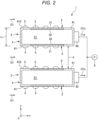
- FIG. 2 is a cross-sectional view of the gas separation apparatus 1 shown in FIG. 1 .
- an X axis, a Y axis, and a Z axis are set as three axes orthogonal to each other.
- Each axis is indicated by an arrow, and a tip side of the arrow is defined as a "positive plus” and a base end side of the arrow is defined as a "negative side.”
- an "X-axis direction” includes both a plus direction and a minus direction of the X axis. The same applies to a Y-axis direction and a Z-axis direction.
- the positive side of the Z axis is also referred to as an "upper side,” and the negative side of the Z axis is also referred to as a “lower side.”
- the Z axis is not required to be parallel to a vertical axis, and may cross the vertical axis.
- the gas separation apparatus 1 shown in FIG. 1 includes two gas separation membrane units 2, 2 (gas separation membrane units according to the embodiment) and an exhaust pump 6.
- the gas separation membrane unit 2 includes a gas separation membrane 3, a gas flow path part 4, and a first convex structure 5.
- the gas separation membrane 3 separates carbon dioxide CO 2 (a predetermined gas component) contained in a mixed gas G1 supplied to a first surface 31 (an obverse surface) by allowing carbon dioxide CO 2 to permeate to a second surface 32 (a reverse surface) with priority over other gas components.
- the gas flow path part 4 has a wall body 41 that defines an internal space S1 through which a gas containing carbon dioxide CO 2 (a gas having a higher concentration of carbon dioxide CO 2 than that of the mixed gas G1) separated and extracted with priority flows.
- the first convex structure 5 protrudes from the first surface 31 of the gas separation membrane 3 and an outer surface 412 of the wall body 41.
- the wall body 41 holds the gas separation membrane 3, and the outer surface 412 of the wall body 41 on which the first convex structure 5 is provided is disposed on the outer periphery of the gas separation membrane 3.
- the first convex structure 5 causes turbulence to the gas flow formed on the first surface 31 of the gas separation membrane 3 under a predetermined condition. Accordingly, even when the carbon dioxide CO 2 in the mixed gas G1 on the first surface 31 passes through the gas separation membrane 3 and the concentration thereof decreases, the new mixed gas G1 is efficiently supplied onto the first surface 31. As a result, the concentration of the carbon dioxide CO 2 on the first surface 31 can be maintained high, and a decrease in separation efficiency in the gas separation membrane 3 can be suppressed.
- the two gas separation membrane units 2, 2 are arranged at a distance from each other in the Z-axis direction. Since the gas separation apparatus 1 includes the plurality of gas separation membrane units 2, 2, the gas separation apparatus 1 having high separation efficiency of carbon dioxide CO 2 can be realized.
- the direction in which the two gas separation membrane units 2, 2 are arranged is not limited to the Z-axis direction (a direction crossing the first surface 31) as long as the direction crosses the first surface 31, but when the direction is the Z-axis direction, the foot print of the gas separation apparatus 1 can be reduced.
- the exhaust pump 6 is coupled to the gas flow path part 4 and discharges the internal space S1 that contains carbon dioxide CO 2 .
- the internal space S1 is depressurized to a pressure level lower than the atmospheric pressure, and a pressure difference is generated between the first surface 31 side and the second surface 32 side of the gas separation membrane 3.
- carbon dioxide CO 2 can be transmitted to be separated using the pressure difference as a driving force.
- the gas separation membrane unit 2 is placed in an environment where the mixed gas G1 exists.
- the mixed gas G1 includes carbon dioxide CO 2 , which is a gas component as a separation target, and other gas components (non-target components).
- the mixed gas G1 is not particularly limited, and is, for example, an exhaust gas discharged from the atmosphere or a facility such as a factory.
- the gas component as the separation target is not limited to carbon dioxide CO 2 , and may be another gas component.
- the non-target component varies depending on the mixed gas G1, but is nitrogen, oxygen, or the like when the mixed gas G1 is air.
- the gas separation membrane unit 2 is exposed to a gas flow of the mixed gas G1.
- the direction of the gas flow of the mixed gas G1 is indicated by arrows.
- the gas flow of the mixed gas G1 is formed from the Y-axis negative side toward the Y-axis positive side.
- the gas flow of the mixed gas G1 may be a natural flow of the air, or a flow generated by a fan not shown.
- the gas flow of the mixed gas G1 may be a flow generated by an exhaust source or a flow generated by a fan not shown.
- the gas separation apparatus 1 may include a fan that generates a gas flow in the mixed gas G1.
- a distance d between the gas separation membrane units 2 in the Z-axis direction is set to be longer than the protrusion height of the first convex structure 5, and is, for example, about 1 mm or more and 1 m or less, and preferably 10 mm or more and 10 cm or less.
- the number of the gas separation membrane units 2 provided to the gas separation apparatus 1 is not limited to two, and may be one, or three or more.
- the gas separation membrane 3 has the first surface 31 and the second surface 32 having an obverse-reverse relationship with each other.
- the gas separation membrane 3 selectively or preferentially allows the carbon dioxide CO 2 contained in the mixed gas G1 supplied to the first surface 31 side to permeate to the second surface 32 side over other gas components. Accordingly, the gas separation membrane 3 has a property that the gas permeability to carbon dioxide CO 2 is higher than the gas permeability to the non-target component (a property that the gas selectivity of carbon dioxide CO 2 is high).
- gas selectivity the ratio of the gas permeability to carbon dioxide to the gas permeability to nitrogen is simply referred to as "gas selectivity.”
- the gas selectivity of the gas separation membrane 3 is preferably 3 or more, and more preferably 10 or more and 1000 or less. When the gas selectivity is within the above range, the gas separation membrane 3 can efficiently separate and recover carbon dioxide CO 2 out of the mixed gas G1.
- the gas permeability to nitrogen in the gas separation membrane 3 and the gas permeability to carbon dioxide in the gas separation membrane 3 are each measured in accordance with a gas permeability test method (Part 1: differential pressure method) defined in JIS K 7126-1:2006.
- a gas permeability measuring device is used for the measurement. Examples of the gas permeability measuring device include GTR-11A/31A manufactured by GTR TEC Corporation. In the device, gas that permeates through the gas separation membrane 3 is introduced into a gas chromatograph to measure the gas permeability to each component.
- the gas permeability to carbon dioxide is preferably 1000 GPU or more, more preferably 5000 GPU or more and 100000 GPU or less, and still more preferably 10000 GPU or more and 50000 GPU or less. Accordingly, it is possible to realize the gas separation membrane 3 capable of reducing the input amount of energy necessary for the separation, specifically, reducing the pressure difference between the first surface 31 side and the second surface 32 side.
- the gas permeability to the carbon dioxide in the gas separation membrane 3 is lower than the lower limit value, a large amount of energy is required for the separation of carbon dioxide, and there is a possibility that an economic efficiency in operation of the gas separation apparatus 1 is reduced.
- the 1 GPU is 3.35 ⁇ 10 -10 mol•m -2 •s -1 •Pa -1 .
- the thickness of the first gas separation membrane 3 is not particularly limited, but is preferably 1 nm or more and 1000 ⁇ m or less, more preferably 5 nm or more and 100 ⁇ m or less, and still more preferably 10 nm or more and 10 ⁇ m or less.
- the average thickness of the gas separation membrane 3 is an average value of thicknesses measured at 10 positions in the gas separation membrane 3.
- the thickness of the gas separation membrane 3 can be measured using, for example, a thickness gauge.
- the size of the first gas separation membrane 3 is not particularly limited, but the maximum length is preferably 5 cm or more and 2 m or less, and more preferably 10 cm or more and 1 m or less. As a result, the gas separation membrane 3 having a mechanical strength enough to withstand the pressure difference and capable of ensuring a sufficient gas permeation amount is obtained.
- the gas separation membrane 3 may be a single layer or a composite layer formed by stacking a plurality of layers.
- the gas separation membrane 3 may be supported by a porous layer that is porous.
- the thickness of the gas separation membrane 3 is 100 ⁇ m or less, it is preferable to laminate the gas separation membrane 3 and the porous layer each other to improve the overall strength.
- Examples of the constituent material of the gas separation membrane 3 include a polymer material, a ceramic material, and a metal material.
- the constituent material of the gas separation membrane 3 may be a composite material of these materials or a composite material of these materials and other materials.
- polymer material examples include polyolefin resins such as polyethylene and polypropylene, fluorine-containing resins such as polytetrafluoroethylene, polyvinyl fluoride, and polyvinylidene fluoride, organopolysiloxane (silicone resin), polystyrene, cellulose, cellulose acetate, polyurethane, polyacrylonitrile, polyphenylene oxide, polysulfone, polyethersulfone, polyimide, polyaramid, and nylon.
- polyolefin resins such as polyethylene and polypropylene
- fluorine-containing resins such as polytetrafluoroethylene, polyvinyl fluoride, and polyvinylidene fluoride
- organopolysiloxane (silicone resin) organopolysiloxane
- polystyrene cellulose, cellulose acetate, polyurethane
- polyacrylonitrile polyphenylene oxide
- polysulfone
- Ceramic material examples include alumina, cordierite, mullite, silicon carbide, and zirconia.
- metal material include stainless steel.
- the gas flow path part 4 includes the wall body 41 that defines the internal space S1 through which the gas containing carbon dioxide CO 2 thus separated flows, and an exhaust port 42 provided to the wall body 41.
- the wall body 41 is a box body which has a flat shape spreading along the X-Y plane, which has a hollow inside, and which has a substantially rectangular parallelepiped shape.
- the internal space S1 is defined by the wall body 41. Further, a part of each of two surfaces crossing the Z axis is opened, and the gas separation membrane 3 is disposed so as to close the opening. Accordingly, as shown in FIG. 2 , the two gas separation membranes 3, 3 arranged vertically are provided to the wall body 41. That is, the two gas separation membranes 3, 3 are disposed such that the second surfaces 32 face each other. Thus, carbon dioxide CO 2 can be separated on both the upper surface side and the lower surface side of the gas separation membrane unit 2.
- the number of the gas separation membranes 3 provided to one wall body 41 is not particularly limited and may be one or three or more.
- the gas separation membrane 3 is disposed so as to cross the Z axis, but the gas separation membrane 3 disposed so as to cross the X axis may be added.
- the exhaust port 42 has a tubular shape and communicates with the internal space S1. As shown in FIG. 1 , the exhaust pump 6 is coupled to the exhaust port 42. By the operation of the exhaust pump 6, the internal space S1 including carbon dioxide CO 2 is exhausted through the exhaust port 42.
- the pressure of the internal space S1 when the exhaust pump 6 is in operation may be lower than the atmospheric pressure, and is preferably 10 kPa or less, and more preferably 1 kPa or less. Accordingly, a sufficient pressure difference can be ensured between the first surface 31 side and the second surface 32 side of the gas separation membrane 3, and the separation efficiency of carbon dioxide CO 2 can sufficiently be increased.
- the lower limit value of the pressure in the internal space S1 is not particularly limited, but is preferably 0.001 Pa or more, and more preferably 0.1 Pa or more in consideration of the introduction cost and the running cost of the exhaust pump 6, the deformation resistance of the gas separation membrane 3, and the like.
- the pressure difference between the internal space S1 and the outside is preferably 0.001 Pa or more and 10 kPa or less, and more preferably 0.1 Pa or more and 1 kPa or less.
- Examples of the constituent materials of the wall body 41 and the exhaust port 42 include a resin material, a metal material, and a ceramic material. In addition, a composite material containing these materials may be used.
- the wall body 41 and the gas separation membrane 3 are bonded to each other so as not to impair airtightness.
- the bonding method is not particularly limited, and examples thereof include bonding with an adhesive, bonding by sandwiching, and bonding by fusion bonding.
- a height h in the Z-axis direction of the wall body 41 is not particularly limited but is preferably 5 mm or more and 30 cm or less, and more preferably 1 cm or more and 10 cm or less. Accordingly, even when a plurality of gas separation membrane units 2 are stacked, an increase in size of the gas separation apparatus 1 can be avoided.
- the maximum length of the wall body 41 along the X-Y plane is not particularly limited but is preferably 5 cm or more and 2 m or less, and more preferably 10 cm or more and 1 m or less. Accordingly, it is possible to realize the gas separation membrane unit 2 capable of arranging the gas separation membranes 3 having a sufficient size and ensuring a sufficient gas permeation amount.
- the first convex structure 5 is a member protruding from the first surface 31 of the gas separation membrane 3 and the outer surface 412 of the wall body 41.
- FIG. 3 is a schematic diagram in which an example of a gas flow is added to a part of the cross-sectional view shown in FIG. 2 .
- FIG. 4 is a schematic diagram in which an example of a gas flow is added to a cross-sectional view of a model (a model of a related-art example) in which the first convex structure 5 is omitted.
- the gas flow of the mixed gas G1 becomes a laminar flow flowing along the first surface 31 and the outer surface 412.
- laminar flow refers to a gas flow flowing parallel to the first surface 31 and the outer surface 412.
- the flow velocity of the laminar flow tends to decrease toward the surface of the object. Therefore, in the vicinity of the first surface 31 of the gas separation membrane 3, the gas exchange efficiency of the mixed gas G1 decreases, and the concentration of carbon dioxide CO 2 decreases.
- a region where the concentration of carbon dioxide CO 2 is low is referred to as a "low-concentration region LC," and is attached with dots. When such the low-concentration region LC is generated, the gas separation membrane 3 does not sufficiently function, and the separation efficiency of carbon dioxide CO 2 decreases.
- the first convex structure 5 when the first convex structure 5 is provided on the first surface 31 or the outer surface 412, as illustrated in FIG. 3 , a part of the gas flow of the mixed gas G1 hits the first convex structure 5 to generate turbulence at the downstream.
- the turbulence includes, for example, a flow of rotating the mixed gas G1 in the Z-axis direction. Therefore, at the downstream of the first convex structure 5, even when the concentration of the carbon dioxide CO 2 at the first surface 31 side decreases due to the permeation of the carbon dioxide CO 2 in the gas separation membrane 3, the concentration is easily recovered because the new mixed gas G1 is continuously supplied due to the influence of the turbulence.
- the generation of the low-concentration region LC as illustrated in FIG. 4 is suppressed, and a decrease in the separation efficiency of carbon dioxide CO 2 can be suppressed.
- the shape, material, arrangement, and the like of the first convex structure 5 are not particularly limited as long as the first convex structure 5 is a member that generates the turbulence as described above.
- the first convex structure 5 is disposed on each of the first surface 31 of the gas separation membrane 3 and the outer surface 412 of the wall body 41.
- the first convex structure 5 is preferably disposed on the first surface 31 or the outer surface 412 in accordance with the arrangement of the gas separation membranes 3. Accordingly, it is possible to suppress the decrease in separation efficiency of carbon dioxide CO 2 in each gas separation membrane 3.
- the number of the first convex structures 5 may be one but is preferably two or more. By providing the plurality of first convex structures 5, it is possible to generate the turbulence in respective parts of the gas separation membrane 3. As a result, a decrease in separation efficiency of carbon dioxide CO 2 can be particularly suppressed.
- the first convex structure 5 may be provided only on one of the first surface 31 of the gas separation membrane 3 and the outer surface 412 of the wall body 41 but is preferably provided to both thereof. This can particularly suppress the decrease in the separation efficiency of carbon dioxide CO 2 .
- the first convex structure 5 is provided on the outer surface 412, it is preferable to dispose the first convex structure 5 at the upstream of the gas separation membrane 3 in the flow of the mixed gas G1.
- the first convex structure 5 preferably protrudes at the upstream of the flow of the mixed gas G1 with respect to the gas separation membrane 3 in the outer surface 412. Accordingly, since the gas separation membrane 3 is located at the downstream of the first convex structure 5, the turbulence is apt to occur on the first surface 31 of the gas separation membrane 3. This makes it easier to obtain the effect of suppressing the decrease in separation efficiency.
- the first convex structure 5 when the first convex structure 5 is provided to the wall body 41, it is possible to avoid a decrease in the effective area of the gas separation membrane 3 as compared with when the first convex structure 5 is provided to the gas separation membrane 3. This can suppress the decrease in separation efficiency.
- the turbulence when the first convex structure 5 is provided to the gas separation membrane 3, the turbulence can be generated over a wide area of the gas separation membrane 3. Accordingly, it is possible to enjoy an advantage of suppressing the decrease in separation efficiency in the wide area.
- the gas flow of the mixed gas G1 is along the Y axis, and the first convex structures 5 are preferably arranged along the X axis.
- the turbulence can be generated in the wide area in the X-axis direction.
- a plurality of rows of the first convex structures 5 extending along the X axis are arranged in the Y-axis direction.
- the turbulence can be generated in the wide area in the Y-axis direction.
- the positions of the first convex structures 5 in the X-axis direction may be aligned with each other or may be shifted from each other. In the latter case, since the region where the turbulence is generated is also shifted, the turbulence can be generated in the wide area of the gas separation membrane 3.
- FIG. 5 is a partial enlarged view showing the first convex structure 5 shown in FIG. 1 .
- the shape of the first convex structure 5 is not particularly limited, but is preferably a shape in which the cross-sectional area in the X-Y plane gradually decreases toward the positive side of the Z axis as illustrated in FIG. 5 when, for example, an installation surface is a surface facing the Z axis positive side.
- an installation surface is a surface facing the Z axis positive side.
- the height H of the first convex structure 5 in the Z-axis direction is not particularly limited, but is preferably 0.1 mm or more and 50 mm or less, more preferably 1 mm or more and 30 mm or less, and still more preferably 3 mm or more and 20 mm or less.
- the appropriate turbulence can be generated without greatly impairing the flow velocity of the mixed gas G1.
- the height H is less than the lower limit value, the turbulence may not be sufficiently generated depending on the flow velocity of the mixed gas G1, the size of the first convex structure 5, and the like.
- the height H exceeds the upper limit value, the flow velocity of the mixed gas G1 may be reduced depending on the size of the first convex structure 5 or the like.
- a length L of the first convex structure 5 in the Y-axis direction is not particularly limited, but is preferably 1 mm or more and 200 mm or less, more preferably 3 mm or more and 100 mm or less, and still more preferably 5 mm or more and 50 mm or less.
- the ratio W/L of the width W to the length L is preferably 0.01 or more and 2.0 or less, more preferably 0.02 or more and 1.0 or less, and still more preferably 0.03 or more and 0.7 or less.
- the ratio W/L is within the above range, the appropriate turbulence can be generated without impairing the flow velocity of the mixed gas G1.
- the ratio W/L is less than the lower limit value, the width of the region where the turbulence occurs may be insufficient.
- the ratio W/L exceeds the upper limit value, the flow velocity of the mixed gas G1 may be impaired, or the appropriate turbulence may not be generated.
- the first convex structure 5 is disposed on the first surface 31 or the outer surface 412 with a method such as adhesion or fusion bonding.
- the first convex structure 5 may be integrated with the first surface 31 or the outer surface 412. That is, the first convex structure 5 may be formed by molding a part of the gas separation membrane 3 or the wall body 41.
- the gas separation membrane 3 is preferably a separate body from the first convex structure 5 from the viewpoint of ease of manufacture.
- the significance of providing the first convex structure 5 becomes more remarkable. Specifically, when the gas permeability is high, the rate at which the concentration of carbon dioxide CO 2 decreases on the first surface 31 of the gas separation membrane 3 is high. Therefore, when the replenishment of the new mixed gas G1 is delayed, it becomes difficult to maintain the concentration of carbon dioxide CO 2 at a high level.
- FIG. 6 is a graph showing the relationship between the gas permeability to carbon dioxide of the gas separation membrane 3 and the concentration of carbon dioxide on the first surface 31 of the gas separation membrane 3.
- the flow velocity is zero, it is assumed that the carbon dioxide spreads in the mixed gas G1 only by the diffusion effect.
- the gas selectivity of the gas separation membrane 3 is assumed to be infinite.
- the gas permeability to the carbon dioxide of the gas separation membrane 3 is 1000 GPU or more, the concentration of the carbon dioxide rapidly decreases. Therefore, when the gas permeability is 1000 GPU or more, the significance of providing the first convex structure 5 is increased. By providing the first convex structure 5, it is possible to realize the gas separation apparatus 1 making the best of the high gas permeability of the gas separation membrane 3.
- FIG. 7 is a graph showing a relationship between the flow velocity of the mixed gas G1 and the concentration ratio of carbon dioxide in the gas separation membrane 3.
- the flow velocity of the mixed gas G1 is a velocity in a direction parallel to the first surface 31 of the gas separation membrane 3.
- the concentration ratio of carbon dioxide is the ratio of the concentration of carbon dioxide at the second surface 32 side to the concentration ratio of carbon dioxide at the first surface 31 side.
- the concentration ratio of the carbon dioxide CO 2 is higher than that when the first convex structure 5 is not provided.
- the flow velocity of the mixed gas G1 is low, this tendency is remarkable. Accordingly, by providing the first convex structure 5, even when a fan is used to provide a flow velocity to the mixed gas G1, a sufficiently high concentration ratio can be realized while suppressing the power consumption of the fan.
- the concentration ratio in FIG. 7 is a calculated value when the mass concentration of carbon dioxide at the first surface 31 side is 400 ppm, the gas selectivity of the gas separation membrane 3 is 10, and the gas permeability to carbon dioxide of the gas separation membrane 3 is 10000 GPU.
- Examples of the exhaust pump 6 include a dry pump such as a screw pump and a scroll pump, an oil rotary pump, and a turbo molecular pump. Among them, a dry pump is preferably used, and a screw pump is more preferably used. These are useful as the exhaust pump 6 because no oil or liquid is used, the internal space S1 is not contaminated, and the power consumption is low.
- FIG. 8 is a cross-sectional view illustrating a configuration of the gas separation apparatus 1 according to the second embodiment.
- the second embodiment is substantially the same as the first embodiment except that a mixed gas supply unit 7 is further provided.
- the gas separation apparatus 1 includes the mixed gas supply unit 7 in addition to the above-described gas separation membrane unit 2.
- the mixed gas supply unit 7 includes a mixed gas flow path part 72, a mixed gas introduction part 74, and a mixed gas discharge part 76.
- the mixed gas flow path part 72 is a flow channel which is provided above and below the gas separation membrane unit 2 and is defined by wall surfaces 33 including the first surfaces 31 of the gas separation membranes 3, and through which the mixed gas G1 flows.
- the mixed gas flow path part 72 includes an upper plate 721 provided at the uppermost area of the gas separation membrane units 2, a lower plate 722 provided at the lowermost area, and two side plates 723 covering side surfaces crossing the X axis.
- the upper plate 721 and the lower plate 722 are located across the two gas separation membrane units 2, 2 in the Z-axis direction.
- the two side plates 723 are located across the two gas separation membrane units 2, 2 in the X-axis direction. Accordingly, the first surfaces 31, the inner surfaces crossing the X axis, and the inner surfaces crossing the Z axis constitute the wall surfaces 33.
- FIG. 8 only illustrates one of the side plates 723.
- Examples of the constituent materials of the upper plate 721, the lower plate 722, and the side plates 723 include a resin material, a metal material, and a ceramic material. In addition, a composite material containing these materials may be used.
- the mixed gas supply unit 7 shown in FIG. 8 includes second convex structures 8 protruding from the wall surfaces 33. Accordingly, the turbulence generated by the second convex structure 8 can also act on the mixed gas G1 located in the vicinity of the first surface 31. As a result, the decrease in the concentration of carbon dioxide CO 2 on the first surface 31 can further be suppressed.
- the configuration of the second convex structure 8 is substantially the same as that of the first convex structure 5 except for the arrangement.
- the second convex structure 8 may be disposed on the wall surface 33 but is preferably disposed on a surface opposite to the first surface 31. This makes it easier for the turbulence generated by the second convex structure 8 to act on the mixed gas G1 located in the vicinity of the first surface 31.
- the mixed gas introduction part 74 introduces the mixed gas G1 into the mixed gas flow path part 72.
- the mixed gas introduction part 74 shown in FIG. 8 includes a feeding fan 742.
- the feeding fan 742 feeds the mixed gas G1 toward the inside of the mixed gas flow path part 72. Accordingly, the flow velocity can be provided to the mixed gas G1 in the mixed gas flow path part 72.
- the mixed gas discharge part 76 discharges a mixed gas G1' from the mixed gas flow path part 72.
- the mixed gas G1' is a mixed gas after being subjected to the separation of carbon dioxide CO 2 in the gas separation membrane unit 2.
- the mixed gas discharge part 76 shown in FIG. 8 has an exhaust fan 762.
- the exhaust fan 762 discharges the mixed gas G1' toward the outside of the mixed gas flow path part 72. Accordingly, the mixed gas G1' having a low concentration of carbon dioxide CO 2 can quickly be discharged, and a decrease in the concentration of carbon dioxide CO 2 on the first surface 31 of the gas separation membrane 3 can more reliably be suppressed.
- the same effects as those of the first embodiment can also be obtained.
- the mixed gas flow path part 72 even when the exhaust gas higher in concentration of carbon dioxide CO 2 than the atmosphere is used as the mixed gas G1, the carbon dioxide CO 2 can be separated while preventing the mixed gas G1 from being diluted with the air. Therefore, even in the case of the mixed gas G1 originally having the high concentration of carbon dioxide CO 2 such as the mixed gas G1 containing high concentration of carbon dioxide CO 2 generated in various plants or the like, it is possible to suppress the decrease in separation efficiency.
- the gas separation membrane unit 2 includes the gas separation membrane 3, the gas flow path part 4, and the first convex structure 5.
- the gas separation membrane 3 separates the carbon dioxide CO 2 (the predetermined gas component) contained in the mixed gas G1 supplied to the first surface 31 by allowing the carbon dioxide CO 2 to permeate to the second surface 32 which is the reverse surface of the first surface 31.
- the gas flow path part 4 has the wall body 41 that defines the internal space S1 through which the gas containing the carbon dioxide CO 2 thus separated flows.
- the first convex structure 5 protrudes from at least one of the first surface 31 of the gas separation membrane 3 and the outer surface 412 of the wall body 41.
- the new mixed gas G1 continues to be rapidly supplied onto the first surface 31 due to the first convex structure 5 causing the turbulence with respect to the gas flow formed on the first surface 31.
- the gas separation membrane unit 2 in which the concentration of the carbon dioxide CO 2 on the first surface 31 is less likely to decrease even when the carbon dioxide CO 2 permeates the gas separation membrane 3, and thus the decrease in separation efficiency can be suppressed is obtained.
- the gas separation membrane unit 2 includes the two gas separation membranes 3, 3 arranged such that the second surfaces 32 are opposed to each other.
- carbon dioxide CO 2 can be separated on both sides (both the upper surface side and the lower surface side) of the gas separation membrane unit 2.
- the first convex structures 5 are disposed respectively on the first surfaces 31 of the two gas separation membranes 3, 3.
- the protruding height of the first convex structure 5 is preferably 0.1 mm or more and 50 mm or less.
- the appropriate turbulence can be generated without greatly impairing the flow velocity of the mixed gas G1.
- the gas permeability to carbon dioxide of the gas separation membrane 3 is preferably 5000 GPU or more and 100000 GPU or less.
- the gas separation membrane 3 capable of reducing the input amount of the energy necessary for the separation, specifically, reducing the pressure difference between the first surface 31 side and the second surface 32 side.
- the gas separation membrane unit 2 which is capable of maximizing the action of the first convex structure 5, and the gas separation membrane 3 for which can easily be procured.
- the gas separation apparatus 1 includes the gas separation membrane unit 2 according to the embodiment and the exhaust pump 6.
- the exhaust pump 6 discharges carbon dioxide CO 2 (the predetermined gas component) flowing through the internal space S1 of the gas flow path part 4.
- the gas separation apparatus 1 capable of separating carbon dioxide CO 2 using the pressure difference is obtained. Further, even when the concentration of carbon dioxide CO 2 in the mixed gas G1 on the first surface 31 of the gas separation membrane 3 decreases due to the action of the gas separation membrane 3, the new mixed gas G1 continues to be rapidly supplied onto the first surface 31 due to the first convex structure 5 causing the turbulence with respect to the gas flow formed on the first surface 31. As a result, the gas separation apparatus 1 in which the concentration of the carbon dioxide CO 2 on the first surface 31 is less likely to decrease even when the carbon dioxide CO 2 permeates the gas separation membrane 3, and thus the decrease in separation efficiency can be suppressed is obtained.
- the gas separation apparatus 1 includes the mixed gas supply unit 7.
- the mixed gas supply unit 7 includes the mixed gas flow path part 72, the mixed gas introduction part 74, and the mixed gas discharge part 76.
- the mixed gas flow path part 72 is defined by the wall surfaces 33 including the first surfaces 31, and the mixed gas G1 flows therethrough.
- the mixed gas introduction part 74 introduces the mixed gas G1 into the mixed gas flow path part 72.
- the mixed gas discharge part 76 discharges the mixed gas G1' from the mixed gas flow path part 72.
- the mixed gas supply unit 7 includes the second convex structure 8 protruding from the wall surface 33.
- the turbulence generated by the second convex structure 8 can also act on the mixed gas G1 located in the vicinity of the first surface 31.
- the decrease in the concentration of carbon dioxide CO 2 on the first surface 31 can further be suppressed.
- the first convex structure 5 protrudes on the outer surface 412 of the wall body 41 at the upstream of the flow of the mixed gas G1 with respect to the gas separation membrane 3.
- the gas separation membrane 3 is located at the downstream of the first convex structure 5, the turbulence is apt to occur on the first surface 31 of the gas separation membrane 3. This makes it easier to obtain the effect of suppressing the decrease in separation efficiency.
- the gas separation apparatus 1 includes at least two gas separation membrane units 2 that are disposed at a distance from each other in a direction crossing the first surface 31.
- the gas separation apparatus 1 high in separation efficiency of carbon dioxide CO 2 can be realized.
- gas separation membrane unit and the gas separation apparatus are hereinabove described based on the illustrated embodiments, the present disclosure is not limited thereto.
- the gas separation membrane unit and gas separation apparatus may be a device in which each unit of the above-described embodiments is replaced with any constituents having substantially the same function, or may be a device in which any constituents are added to the above-described embodiments.
Landscapes
- Chemical & Material Sciences (AREA)
- Chemical Kinetics & Catalysis (AREA)
- Engineering & Computer Science (AREA)
- Analytical Chemistry (AREA)
- General Chemical & Material Sciences (AREA)
- Oil, Petroleum & Natural Gas (AREA)
- Separation Using Semi-Permeable Membranes (AREA)
Abstract
Description
- The present application is based on, and claims priority from
JP Application Serial Number 2023-124536, filed July 31, 2023 - The present disclosure relates to a gas separation membrane unit and a gas separation apparatus.
- In order to implement carbon neutrality or carbon minus, a technique is being considered to absorb and collect carbon dioxide discharged from thermal power plants, boiler facilities, or the like, and carbon dioxide in the atmosphere. As that technique, there has been known a membrane separation method of separating carbon dioxide using a gas separation membrane.
- For example,
JP-A-2023-033590 - According to such a gas separation method, the gas (A) can be satisfactorily separated even under a moderate condition in which the pressure difference between both of the surfaces of the gas separation membrane is 1 atm or less.
-
JP-A-2023-033590 - In the membrane separation method, it is a problem to improve separation efficiency of a predetermined gas component. In order to increase the separation efficiency of the gas separation membrane, it is necessary to maintain a high concentration of a predetermined gas component at the upstream of the gas separation membrane. However, when a predetermined gas component passes through the gas separation membrane, the concentration of the gas component at the upstream decreases, resulting in a decrease in separation efficiency.
- Therefore, it is required to realize a gas separation device in which a concentration of a predetermined gas component hardly decreases even when the predetermined gas component passes through a gas separation membrane and a decrease in separation efficiency can be suppressed.
- A gas separation membrane unit according to an application example of the present disclosure includes:
- a gas separation membrane configured to separate a predetermined gas component contained in a mixed gas supplied to a first surface by allowing the predetermined gas component to permeate to a second surface that is a reverse surface of the first surface;
- a gas flow path part including a wall body configured to define an internal space through which the predetermined gas component separated flows; and
- a first convex structure protruding from at least one of the first surface of the gas separation membrane and an outer surface of the wall body.
- A gas separation apparatus according to an application example of the present disclosure includes:
- the gas separation membrane unit according to the application example of the present disclosure; and
- an exhaust pump configured to exhaust the predetermined gas component flowing through the internal space of the gas flow path part.
-
-
FIG. 1 is a perspective view illustrating a configuration of a gas separation apparatus according to a first embodiment. -
FIG. 2 is a cross-sectional view of the gas separation apparatus shown inFIG. 1 . -
FIG. 3 is a schematic diagram in which an example of a gas flow is added to a part of the cross-sectional view shown inFIG. 2 . -
FIG. 4 is a schematic diagram in which an example of a gas flow is added to a cross-sectional view of a model (a model of a related-art example) in which a first convex structure is omitted. -
FIG. 5 is a partial enlarged view illustrating the first convex structure inFIG. 1 . -
FIG. 6 is a graph showing a relationship between the gas permeability to carbon dioxide in a gas separation membrane and the concentration of carbon dioxide on a first surface of the gas separation membrane. -
FIG. 7 is a graph showing a relationship between a flow velocity of a mixed gas and a concentration ratio of carbon dioxide in the gas separation membrane. -
FIG. 8 is a cross-sectional view illustrating a configuration of a gas separation apparatus according to a second embodiment. - Hereinafter, a gas separation membrane unit and a gas separation apparatus of the present disclosure will be described in detail based on some embodiments illustrated in the accompanying drawings.
- First, a gas separation membrane unit and a gas separation apparatus according to a first embodiment will be described.
-
FIG. 1 is a perspective view illustrating a configuration of agas separation apparatus 1 according to the first embodiment.FIG. 2 is a cross-sectional view of thegas separation apparatus 1 shown inFIG. 1 . - In the drawings of the present application, an X axis, a Y axis, and a Z axis are set as three axes orthogonal to each other. Each axis is indicated by an arrow, and a tip side of the arrow is defined as a "positive plus" and a base end side of the arrow is defined as a "negative side." In the following description, for example, an "X-axis direction" includes both a plus direction and a minus direction of the X axis. The same applies to a Y-axis direction and a Z-axis direction. In the following description, in particular, the positive side of the Z axis is also referred to as an "upper side," and the negative side of the Z axis is also referred to as a "lower side." However, the Z axis is not required to be parallel to a vertical axis, and may cross the vertical axis.
- The
gas separation apparatus 1 shown inFIG. 1 includes two gasseparation membrane units 2, 2 (gas separation membrane units according to the embodiment) and anexhaust pump 6. The gasseparation membrane unit 2 includes agas separation membrane 3, a gasflow path part 4, and afirst convex structure 5. Thegas separation membrane 3 separates carbon dioxide CO2 (a predetermined gas component) contained in a mixed gas G1 supplied to a first surface 31 (an obverse surface) by allowing carbon dioxide CO2 to permeate to a second surface 32 (a reverse surface) with priority over other gas components. The gasflow path part 4 has awall body 41 that defines an internal space S1 through which a gas containing carbon dioxide CO2 (a gas having a higher concentration of carbon dioxide CO2 than that of the mixed gas G1) separated and extracted with priority flows. Thefirst convex structure 5 protrudes from thefirst surface 31 of thegas separation membrane 3 and anouter surface 412 of thewall body 41. Thewall body 41 holds thegas separation membrane 3, and theouter surface 412 of thewall body 41 on which thefirst convex structure 5 is provided is disposed on the outer periphery of thegas separation membrane 3. - In such a gas
separation membrane unit 2, thefirst convex structure 5 causes turbulence to the gas flow formed on thefirst surface 31 of thegas separation membrane 3 under a predetermined condition. Accordingly, even when the carbon dioxide CO2 in the mixed gas G1 on thefirst surface 31 passes through thegas separation membrane 3 and the concentration thereof decreases, the new mixed gas G1 is efficiently supplied onto thefirst surface 31. As a result, the concentration of the carbon dioxide CO2 on thefirst surface 31 can be maintained high, and a decrease in separation efficiency in thegas separation membrane 3 can be suppressed. - In the
gas separation apparatus 1 shown inFIG. 1 , the two gasseparation membrane units gas separation apparatus 1 includes the plurality of gasseparation membrane units gas separation apparatus 1 having high separation efficiency of carbon dioxide CO2 can be realized. - The direction in which the two gas
separation membrane units first surface 31, but when the direction is the Z-axis direction, the foot print of thegas separation apparatus 1 can be reduced. - The
exhaust pump 6 is coupled to the gasflow path part 4 and discharges the internal space S1 that contains carbon dioxide CO2. As a result, the internal space S1 is depressurized to a pressure level lower than the atmospheric pressure, and a pressure difference is generated between thefirst surface 31 side and thesecond surface 32 side of thegas separation membrane 3. In thegas separation membrane 3, carbon dioxide CO2 can be transmitted to be separated using the pressure difference as a driving force. - The gas
separation membrane unit 2 is placed in an environment where the mixed gas G1 exists. The mixed gas G1 includes carbon dioxide CO2, which is a gas component as a separation target, and other gas components (non-target components). The mixed gas G1 is not particularly limited, and is, for example, an exhaust gas discharged from the atmosphere or a facility such as a factory. The gas component as the separation target is not limited to carbon dioxide CO2, and may be another gas component. The non-target component varies depending on the mixed gas G1, but is nitrogen, oxygen, or the like when the mixed gas G1 is air. - The gas
separation membrane unit 2 is exposed to a gas flow of the mixed gas G1. In each drawing of the present application, the direction of the gas flow of the mixed gas G1 is indicated by arrows. In the present embodiment, the gas flow of the mixed gas G1 is formed from the Y-axis negative side toward the Y-axis positive side. By the gasseparation membrane unit 2 being exposed to the gas flow, the mixed gas G1 high in concentration of carbon dioxide CO2 is continuously supplied. Accordingly, the separation efficiency of carbon dioxide CO2 in the gasseparation membrane unit 2 can be kept high. In the present specification, regarding the gas flow of the mixed gas G1, the Y-axis negative side is referred to as "upstream," and the Y-axis positive side is referred to as "downstream." - When the mixed gas G1 is the air, the gas flow of the mixed gas G1 may be a natural flow of the air, or a flow generated by a fan not shown. Also, when the mixed gas G1 is an exhaust gas, the gas flow of the mixed gas G1 may be a flow generated by an exhaust source or a flow generated by a fan not shown. The
gas separation apparatus 1 may include a fan that generates a gas flow in the mixed gas G1. - A distance d between the gas
separation membrane units 2 in the Z-axis direction is set to be longer than the protrusion height of the firstconvex structure 5, and is, for example, about 1 mm or more and 1 m or less, and preferably 10 mm or more and 10 cm or less. - The number of the gas
separation membrane units 2 provided to thegas separation apparatus 1 is not limited to two, and may be one, or three or more. - The
gas separation membrane 3 has thefirst surface 31 and thesecond surface 32 having an obverse-reverse relationship with each other. Thegas separation membrane 3 selectively or preferentially allows the carbon dioxide CO2 contained in the mixed gas G1 supplied to thefirst surface 31 side to permeate to thesecond surface 32 side over other gas components. Accordingly, thegas separation membrane 3 has a property that the gas permeability to carbon dioxide CO2 is higher than the gas permeability to the non-target component (a property that the gas selectivity of carbon dioxide CO2 is high). Hereinafter, the ratio of the gas permeability to carbon dioxide to the gas permeability to nitrogen is simply referred to as "gas selectivity." - The gas selectivity of the
gas separation membrane 3 is preferably 3 or more, and more preferably 10 or more and 1000 or less. When the gas selectivity is within the above range, thegas separation membrane 3 can efficiently separate and recover carbon dioxide CO2 out of the mixed gas G1. - The gas permeability to nitrogen in the
gas separation membrane 3 and the gas permeability to carbon dioxide in thegas separation membrane 3 are each measured in accordance with a gas permeability test method (Part 1: differential pressure method) defined in JIS K 7126-1:2006. A gas permeability measuring device is used for the measurement. Examples of the gas permeability measuring device include GTR-11A/31A manufactured by GTR TEC Corporation. In the device, gas that permeates through thegas separation membrane 3 is introduced into a gas chromatograph to measure the gas permeability to each component. - In the
gas separation membrane 3, the gas permeability to carbon dioxide is preferably 1000 GPU or more, more preferably 5000 GPU or more and 100000 GPU or less, and still more preferably 10000 GPU or more and 50000 GPU or less. Accordingly, it is possible to realize thegas separation membrane 3 capable of reducing the input amount of energy necessary for the separation, specifically, reducing the pressure difference between thefirst surface 31 side and thesecond surface 32 side. When the gas permeability to the carbon dioxide in thegas separation membrane 3 is lower than the lower limit value, a large amount of energy is required for the separation of carbon dioxide, and there is a possibility that an economic efficiency in operation of thegas separation apparatus 1 is reduced. On the other hand, when the gas permeability to the carbon dioxide in thegas separation membrane 3 exceeds the upper limit value, the cost for manufacturing (procuring) thegas separation membrane 3 may increase. The 1 GPU is 3.35×10⁻¹⁰ mol•m-2 •s-1•Pa-1. - The thickness of the first
gas separation membrane 3 is not particularly limited, but is preferably 1 nm or more and 1000 µm or less, more preferably 5 nm or more and 100 µm or less, and still more preferably 10 nm or more and 10 µm or less. - The average thickness of the
gas separation membrane 3 is an average value of thicknesses measured at 10 positions in thegas separation membrane 3. The thickness of thegas separation membrane 3 can be measured using, for example, a thickness gauge. - The size of the first
gas separation membrane 3 is not particularly limited, but the maximum length is preferably 5 cm or more and 2 m or less, and more preferably 10 cm or more and 1 m or less. As a result, thegas separation membrane 3 having a mechanical strength enough to withstand the pressure difference and capable of ensuring a sufficient gas permeation amount is obtained. - The
gas separation membrane 3 may be a single layer or a composite layer formed by stacking a plurality of layers. Thegas separation membrane 3 may be supported by a porous layer that is porous. In particular, when the thickness of thegas separation membrane 3 is 100 µm or less, it is preferable to laminate thegas separation membrane 3 and the porous layer each other to improve the overall strength. - Examples of the constituent material of the
gas separation membrane 3 include a polymer material, a ceramic material, and a metal material. The constituent material of thegas separation membrane 3 may be a composite material of these materials or a composite material of these materials and other materials. - Examples of the polymer material include polyolefin resins such as polyethylene and polypropylene, fluorine-containing resins such as polytetrafluoroethylene, polyvinyl fluoride, and polyvinylidene fluoride, organopolysiloxane (silicone resin), polystyrene, cellulose, cellulose acetate, polyurethane, polyacrylonitrile, polyphenylene oxide, polysulfone, polyethersulfone, polyimide, polyaramid, and nylon.
- Examples of the ceramic material include alumina, cordierite, mullite, silicon carbide, and zirconia. Examples of the metal material include stainless steel.
- The gas
flow path part 4 includes thewall body 41 that defines the internal space S1 through which the gas containing carbon dioxide CO2 thus separated flows, and anexhaust port 42 provided to thewall body 41. - The
wall body 41 is a box body which has a flat shape spreading along the X-Y plane, which has a hollow inside, and which has a substantially rectangular parallelepiped shape. The internal space S1 is defined by thewall body 41. Further, a part of each of two surfaces crossing the Z axis is opened, and thegas separation membrane 3 is disposed so as to close the opening. Accordingly, as shown inFIG. 2 , the twogas separation membranes wall body 41. That is, the twogas separation membranes second surfaces 32 face each other. Thus, carbon dioxide CO2 can be separated on both the upper surface side and the lower surface side of the gasseparation membrane unit 2. The number of thegas separation membranes 3 provided to onewall body 41 is not particularly limited and may be one or three or more. In the present embodiment, thegas separation membrane 3 is disposed so as to cross the Z axis, but thegas separation membrane 3 disposed so as to cross the X axis may be added. - The
exhaust port 42 has a tubular shape and communicates with the internal space S1. As shown inFIG. 1 , theexhaust pump 6 is coupled to theexhaust port 42. By the operation of theexhaust pump 6, the internal space S1 including carbon dioxide CO2 is exhausted through theexhaust port 42. The pressure of the internal space S1 when theexhaust pump 6 is in operation may be lower than the atmospheric pressure, and is preferably 10 kPa or less, and more preferably 1 kPa or less. Accordingly, a sufficient pressure difference can be ensured between thefirst surface 31 side and thesecond surface 32 side of thegas separation membrane 3, and the separation efficiency of carbon dioxide CO2 can sufficiently be increased. The lower limit value of the pressure in the internal space S1 is not particularly limited, but is preferably 0.001 Pa or more, and more preferably 0.1 Pa or more in consideration of the introduction cost and the running cost of theexhaust pump 6, the deformation resistance of thegas separation membrane 3, and the like. In view of this, the pressure difference between the internal space S1 and the outside is preferably 0.001 Pa or more and 10 kPa or less, and more preferably 0.1 Pa or more and 1 kPa or less. - Examples of the constituent materials of the
wall body 41 and theexhaust port 42 include a resin material, a metal material, and a ceramic material. In addition, a composite material containing these materials may be used. - The
wall body 41 and thegas separation membrane 3 are bonded to each other so as not to impair airtightness. The bonding method is not particularly limited, and examples thereof include bonding with an adhesive, bonding by sandwiching, and bonding by fusion bonding. - A height h in the Z-axis direction of the
wall body 41 is not particularly limited but is preferably 5 mm or more and 30 cm or less, and more preferably 1 cm or more and 10 cm or less. Accordingly, even when a plurality of gasseparation membrane units 2 are stacked, an increase in size of thegas separation apparatus 1 can be avoided. - The maximum length of the
wall body 41 along the X-Y plane is not particularly limited but is preferably 5 cm or more and 2 m or less, and more preferably 10 cm or more and 1 m or less. Accordingly, it is possible to realize the gasseparation membrane unit 2 capable of arranging thegas separation membranes 3 having a sufficient size and ensuring a sufficient gas permeation amount. - The first
convex structure 5 is a member protruding from thefirst surface 31 of thegas separation membrane 3 and theouter surface 412 of thewall body 41. -
FIG. 3 is a schematic diagram in which an example of a gas flow is added to a part of the cross-sectional view shown inFIG. 2 .FIG. 4 is a schematic diagram in which an example of a gas flow is added to a cross-sectional view of a model (a model of a related-art example) in which the firstconvex structure 5 is omitted. - As shown in
FIG. 4 , when the firstconvex structure 5 is not provided, the gas flow of the mixed gas G1 becomes a laminar flow flowing along thefirst surface 31 and theouter surface 412. In the present specification, the "laminar flow" refers to a gas flow flowing parallel to thefirst surface 31 and theouter surface 412. The flow velocity of the laminar flow tends to decrease toward the surface of the object. Therefore, in the vicinity of thefirst surface 31 of thegas separation membrane 3, the gas exchange efficiency of the mixed gas G1 decreases, and the concentration of carbon dioxide CO2 decreases. InFIG. 4 , a region where the concentration of carbon dioxide CO2 is low is referred to as a "low-concentration region LC," and is attached with dots. When such the low-concentration region LC is generated, thegas separation membrane 3 does not sufficiently function, and the separation efficiency of carbon dioxide CO2 decreases. - In contrast, when the first
convex structure 5 is provided on thefirst surface 31 or theouter surface 412, as illustrated inFIG. 3 , a part of the gas flow of the mixed gas G1 hits the firstconvex structure 5 to generate turbulence at the downstream. The turbulence includes, for example, a flow of rotating the mixed gas G1 in the Z-axis direction. Therefore, at the downstream of the firstconvex structure 5, even when the concentration of the carbon dioxide CO2 at thefirst surface 31 side decreases due to the permeation of the carbon dioxide CO2 in thegas separation membrane 3, the concentration is easily recovered because the new mixed gas G1 is continuously supplied due to the influence of the turbulence. As a result, in thegas separation apparatus 1 illustrated inFIG. 3 , the generation of the low-concentration region LC as illustrated inFIG. 4 is suppressed, and a decrease in the separation efficiency of carbon dioxide CO2 can be suppressed. - The shape, material, arrangement, and the like of the first
convex structure 5 are not particularly limited as long as the firstconvex structure 5 is a member that generates the turbulence as described above. InFIG. 1 , the firstconvex structure 5 is disposed on each of thefirst surface 31 of thegas separation membrane 3 and theouter surface 412 of thewall body 41. When the plurality ofgas separation membranes 3 are provided to onewall body 41, the firstconvex structure 5 is preferably disposed on thefirst surface 31 or theouter surface 412 in accordance with the arrangement of thegas separation membranes 3. Accordingly, it is possible to suppress the decrease in separation efficiency of carbon dioxide CO2 in eachgas separation membrane 3. - The number of the first
convex structures 5 may be one but is preferably two or more. By providing the plurality of firstconvex structures 5, it is possible to generate the turbulence in respective parts of thegas separation membrane 3. As a result, a decrease in separation efficiency of carbon dioxide CO2 can be particularly suppressed. - The first
convex structure 5 may be provided only on one of thefirst surface 31 of thegas separation membrane 3 and theouter surface 412 of thewall body 41 but is preferably provided to both thereof. This can particularly suppress the decrease in the separation efficiency of carbon dioxide CO2. When the firstconvex structure 5 is provided on theouter surface 412, it is preferable to dispose the firstconvex structure 5 at the upstream of thegas separation membrane 3 in the flow of the mixed gas G1. Specifically, the firstconvex structure 5 preferably protrudes at the upstream of the flow of the mixed gas G1 with respect to thegas separation membrane 3 in theouter surface 412. Accordingly, since thegas separation membrane 3 is located at the downstream of the firstconvex structure 5, the turbulence is apt to occur on thefirst surface 31 of thegas separation membrane 3. This makes it easier to obtain the effect of suppressing the decrease in separation efficiency. - Further, when the first
convex structure 5 is provided to thewall body 41, it is possible to avoid a decrease in the effective area of thegas separation membrane 3 as compared with when the firstconvex structure 5 is provided to thegas separation membrane 3. This can suppress the decrease in separation efficiency. On the other hand, when the firstconvex structure 5 is provided to thegas separation membrane 3, the turbulence can be generated over a wide area of thegas separation membrane 3. Accordingly, it is possible to enjoy an advantage of suppressing the decrease in separation efficiency in the wide area. - The gas flow of the mixed gas G1 is along the Y axis, and the first
convex structures 5 are preferably arranged along the X axis. Thus, the turbulence can be generated in the wide area in the X-axis direction. Further, inFIG. 1 , a plurality of rows of the firstconvex structures 5 extending along the X axis are arranged in the Y-axis direction. Thus, the turbulence can be generated in the wide area in the Y-axis direction. - Furthermore, in the rows of the first
convex structures 5, the positions of the firstconvex structures 5 in the X-axis direction may be aligned with each other or may be shifted from each other. In the latter case, since the region where the turbulence is generated is also shifted, the turbulence can be generated in the wide area of thegas separation membrane 3. -
FIG. 5 is a partial enlarged view showing the firstconvex structure 5 shown inFIG. 1 . - The shape of the first
convex structure 5 is not particularly limited, but is preferably a shape in which the cross-sectional area in the X-Y plane gradually decreases toward the positive side of the Z axis as illustrated inFIG. 5 when, for example, an installation surface is a surface facing the Z axis positive side. When adopting such a shape, it is possible to generate the turbulence without greatly impairing the flow velocity of the mixed gas G1. As a result, a decrease in separation efficiency of carbon dioxide CO2 can be particularly suppressed. - The height H of the first
convex structure 5 in the Z-axis direction is not particularly limited, but is preferably 0.1 mm or more and 50 mm or less, more preferably 1 mm or more and 30 mm or less, and still more preferably 3 mm or more and 20 mm or less. When the height H is within the above range, the appropriate turbulence can be generated without greatly impairing the flow velocity of the mixed gas G1. When the height H is less than the lower limit value, the turbulence may not be sufficiently generated depending on the flow velocity of the mixed gas G1, the size of the firstconvex structure 5, and the like. On the other hand, when the height H exceeds the upper limit value, the flow velocity of the mixed gas G1 may be reduced depending on the size of the firstconvex structure 5 or the like. - A length L of the first
convex structure 5 in the Y-axis direction is not particularly limited, but is preferably 1 mm or more and 200 mm or less, more preferably 3 mm or more and 100 mm or less, and still more preferably 5 mm or more and 50 mm or less. - When the width of the first
convex structure 5 in the X-axis direction is W, the ratio W/L of the width W to the length L is preferably 0.01 or more and 2.0 or less, more preferably 0.02 or more and 1.0 or less, and still more preferably 0.03 or more and 0.7 or less. When the ratio W/L is within the above range, the appropriate turbulence can be generated without impairing the flow velocity of the mixed gas G1. When the ratio W/L is less than the lower limit value, the width of the region where the turbulence occurs may be insufficient. On the other hand, when the ratio W/L exceeds the upper limit value, the flow velocity of the mixed gas G1 may be impaired, or the appropriate turbulence may not be generated. - The first
convex structure 5 is disposed on thefirst surface 31 or theouter surface 412 with a method such as adhesion or fusion bonding. The firstconvex structure 5 may be integrated with thefirst surface 31 or theouter surface 412. That is, the firstconvex structure 5 may be formed by molding a part of thegas separation membrane 3 or thewall body 41. However, thegas separation membrane 3 is preferably a separate body from the firstconvex structure 5 from the viewpoint of ease of manufacture. - In addition, when the gas permeability to carbon dioxide CO2 of the
gas separation membrane 3 is within the above range, the significance of providing the firstconvex structure 5 becomes more remarkable. Specifically, when the gas permeability is high, the rate at which the concentration of carbon dioxide CO2 decreases on thefirst surface 31 of thegas separation membrane 3 is high. Therefore, when the replenishment of the new mixed gas G1 is delayed, it becomes difficult to maintain the concentration of carbon dioxide CO2 at a high level. -
FIG. 6 is a graph showing the relationship between the gas permeability to carbon dioxide of thegas separation membrane 3 and the concentration of carbon dioxide on thefirst surface 31 of thegas separation membrane 3. In the graph shown inFIG. 6 , the concentration of carbon dioxide on thefirst surface 31 when the flow velocity of the mixed gas G1 having a carbon dioxide concentration of 400 ppm supplied onto thefirst surface 31 was zero, and one second elapsed from the supply of the mixed gas G1 is plotted. In this case, since the flow velocity is zero, it is assumed that the carbon dioxide spreads in the mixed gas G1 only by the diffusion effect. The gas selectivity of thegas separation membrane 3 is assumed to be infinite. - As is clear from
FIG. 6 , when the gas permeability to the carbon dioxide of thegas separation membrane 3 is 1000 GPU or more, the concentration of the carbon dioxide rapidly decreases. Therefore, when the gas permeability is 1000 GPU or more, the significance of providing the firstconvex structure 5 is increased. By providing the firstconvex structure 5, it is possible to realize thegas separation apparatus 1 making the best of the high gas permeability of thegas separation membrane 3. -
FIG. 7 is a graph showing a relationship between the flow velocity of the mixed gas G1 and the concentration ratio of carbon dioxide in thegas separation membrane 3. The flow velocity of the mixed gas G1 is a velocity in a direction parallel to thefirst surface 31 of thegas separation membrane 3. The concentration ratio of carbon dioxide is the ratio of the concentration of carbon dioxide at thesecond surface 32 side to the concentration ratio of carbon dioxide at thefirst surface 31 side. - As is clear from
FIG. 7 , when the firstconvex structure 5 is provided, the concentration ratio of the carbon dioxide CO2 is higher than that when the firstconvex structure 5 is not provided. In particular, it is understood that when the flow velocity of the mixed gas G1 is low, this tendency is remarkable. Accordingly, by providing the firstconvex structure 5, even when a fan is used to provide a flow velocity to the mixed gas G1, a sufficiently high concentration ratio can be realized while suppressing the power consumption of the fan. - Based on the calculation example of
FIG. 7 , when the flow velocity of the mixed gas G1 is in a range of more than 0 m/s and 5 m/s or less, it can be said that the significance of providing the firstconvex structure 5 becomes higher. The concentration ratio inFIG. 7 is a calculated value when the mass concentration of carbon dioxide at thefirst surface 31 side is 400 ppm, the gas selectivity of thegas separation membrane 3 is 10, and the gas permeability to carbon dioxide of thegas separation membrane 3 is 10000 GPU. - Examples of the
exhaust pump 6 include a dry pump such as a screw pump and a scroll pump, an oil rotary pump, and a turbo molecular pump. Among them, a dry pump is preferably used, and a screw pump is more preferably used. These are useful as theexhaust pump 6 because no oil or liquid is used, the internal space S1 is not contaminated, and the power consumption is low. - Next, a gas separation membrane unit and a gas separation apparatus according to a second embodiment will be described.
-
FIG. 8 is a cross-sectional view illustrating a configuration of thegas separation apparatus 1 according to the second embodiment. - Hereinafter, the second embodiment will be described, and in the following description, differences from the first embodiment will be mainly described, and description of similar matters will be omitted.
- The second embodiment is substantially the same as the first embodiment except that a mixed
gas supply unit 7 is further provided. - As shown in
FIG. 8 , thegas separation apparatus 1 according to the second embodiment includes the mixedgas supply unit 7 in addition to the above-described gasseparation membrane unit 2. The mixedgas supply unit 7 includes a mixed gasflow path part 72, a mixedgas introduction part 74, and a mixedgas discharge part 76. - The mixed gas
flow path part 72 is a flow channel which is provided above and below the gasseparation membrane unit 2 and is defined bywall surfaces 33 including thefirst surfaces 31 of thegas separation membranes 3, and through which the mixed gas G1 flows. Specifically, as shown inFIG. 8 , the mixed gasflow path part 72 includes anupper plate 721 provided at the uppermost area of the gasseparation membrane units 2, alower plate 722 provided at the lowermost area, and twoside plates 723 covering side surfaces crossing the X axis. Theupper plate 721 and thelower plate 722 are located across the two gasseparation membrane units side plates 723 are located across the two gasseparation membrane units first surfaces 31, the inner surfaces crossing the X axis, and the inner surfaces crossing the Z axis constitute the wall surfaces 33.FIG. 8 only illustrates one of theside plates 723. - Examples of the constituent materials of the
upper plate 721, thelower plate 722, and theside plates 723 include a resin material, a metal material, and a ceramic material. In addition, a composite material containing these materials may be used. - The mixed
gas supply unit 7 shown inFIG. 8 includes secondconvex structures 8 protruding from the wall surfaces 33. Accordingly, the turbulence generated by the secondconvex structure 8 can also act on the mixed gas G1 located in the vicinity of thefirst surface 31. As a result, the decrease in the concentration of carbon dioxide CO2 on thefirst surface 31 can further be suppressed. - The configuration of the second
convex structure 8 is substantially the same as that of the firstconvex structure 5 except for the arrangement. The secondconvex structure 8 may be disposed on thewall surface 33 but is preferably disposed on a surface opposite to thefirst surface 31. This makes it easier for the turbulence generated by the secondconvex structure 8 to act on the mixed gas G1 located in the vicinity of thefirst surface 31. - The mixed
gas introduction part 74 introduces the mixed gas G1 into the mixed gasflow path part 72. The mixedgas introduction part 74 shown inFIG. 8 includes a feedingfan 742. The feedingfan 742 feeds the mixed gas G1 toward the inside of the mixed gasflow path part 72. Accordingly, the flow velocity can be provided to the mixed gas G1 in the mixed gasflow path part 72. - The mixed
gas discharge part 76 discharges a mixed gas G1' from the mixed gasflow path part 72. The mixed gas G1' is a mixed gas after being subjected to the separation of carbon dioxide CO2 in the gasseparation membrane unit 2. The mixedgas discharge part 76 shown inFIG. 8 has anexhaust fan 762. Theexhaust fan 762 discharges the mixed gas G1' toward the outside of the mixed gasflow path part 72. Accordingly, the mixed gas G1' having a low concentration of carbon dioxide CO2 can quickly be discharged, and a decrease in the concentration of carbon dioxide CO2 on thefirst surface 31 of thegas separation membrane 3 can more reliably be suppressed. - In the second embodiment as described above, the same effects as those of the first embodiment can also be obtained. Further, in the second embodiment, by providing the mixed gas
flow path part 72, even when the exhaust gas higher in concentration of carbon dioxide CO2 than the atmosphere is used as the mixed gas G1, the carbon dioxide CO2 can be separated while preventing the mixed gas G1 from being diluted with the air. Therefore, even in the case of the mixed gas G1 originally having the high concentration of carbon dioxide CO2 such as the mixed gas G1 containing high concentration of carbon dioxide CO2 generated in various plants or the like, it is possible to suppress the decrease in separation efficiency. - As described above, the gas
separation membrane unit 2 according to the embodiment includes thegas separation membrane 3, the gasflow path part 4, and the firstconvex structure 5. Thegas separation membrane 3 separates the carbon dioxide CO2 (the predetermined gas component) contained in the mixed gas G1 supplied to thefirst surface 31 by allowing the carbon dioxide CO2 to permeate to thesecond surface 32 which is the reverse surface of thefirst surface 31. The gasflow path part 4 has thewall body 41 that defines the internal space S1 through which the gas containing the carbon dioxide CO2 thus separated flows. The firstconvex structure 5 protrudes from at least one of thefirst surface 31 of thegas separation membrane 3 and theouter surface 412 of thewall body 41. - According to such a configuration, even when the concentration of carbon dioxide CO2 in the mixed gas G1 on the
first surface 31 of thegas separation membrane 3 decreases due to the action of thegas separation membrane 3, the new mixed gas G1 continues to be rapidly supplied onto thefirst surface 31 due to the firstconvex structure 5 causing the turbulence with respect to the gas flow formed on thefirst surface 31. As a result, the gasseparation membrane unit 2 in which the concentration of the carbon dioxide CO2 on thefirst surface 31 is less likely to decrease even when the carbon dioxide CO2 permeates thegas separation membrane 3, and thus the decrease in separation efficiency can be suppressed is obtained. - The gas
separation membrane unit 2 according to the embodiment includes the twogas separation membranes second surfaces 32 are opposed to each other. - According to such a configuration, carbon dioxide CO2 can be separated on both sides (both the upper surface side and the lower surface side) of the gas
separation membrane unit 2. - In the gas
separation membrane unit 2 according to the embodiment, the firstconvex structures 5 are disposed respectively on thefirst surfaces 31 of the twogas separation membranes - According to such a configuration, it is possible to suppress the decrease in separation efficiency of carbon dioxide CO2 in each
gas separation membrane 3. - The protruding height of the first
convex structure 5 is preferably 0.1 mm or more and 50 mm or less. - When the height H is within the above range, the appropriate turbulence can be generated without greatly impairing the flow velocity of the mixed gas G1.
- The gas permeability to carbon dioxide of the
gas separation membrane 3 is preferably 5000 GPU or more and 100000 GPU or less. - According to such a configuration, it is possible to realize the
gas separation membrane 3 capable of reducing the input amount of the energy necessary for the separation, specifically, reducing the pressure difference between thefirst surface 31 side and thesecond surface 32 side. In addition, it is possible to realize the gasseparation membrane unit 2 which is capable of maximizing the action of the firstconvex structure 5, and thegas separation membrane 3 for which can easily be procured. - The
gas separation apparatus 1 according to the embodiment includes the gasseparation membrane unit 2 according to the embodiment and theexhaust pump 6. Theexhaust pump 6 discharges carbon dioxide CO2 (the predetermined gas component) flowing through the internal space S1 of the gasflow path part 4. - According to such a configuration, it is possible to reduce the pressure in the internal space S1 to the level lower than the atmospheric pressure, and generate the pressure difference between the
first surface 31 side and thesecond surface 32 side of thegas separation membrane 3. Thegas separation apparatus 1 capable of separating carbon dioxide CO2 using the pressure difference is obtained. Further, even when the concentration of carbon dioxide CO2 in the mixed gas G1 on thefirst surface 31 of thegas separation membrane 3 decreases due to the action of thegas separation membrane 3, the new mixed gas G1 continues to be rapidly supplied onto thefirst surface 31 due to the firstconvex structure 5 causing the turbulence with respect to the gas flow formed on thefirst surface 31. As a result, thegas separation apparatus 1 in which the concentration of the carbon dioxide CO2 on thefirst surface 31 is less likely to decrease even when the carbon dioxide CO2 permeates thegas separation membrane 3, and thus the decrease in separation efficiency can be suppressed is obtained. - The
gas separation apparatus 1 according to the embodiment includes the mixedgas supply unit 7. The mixedgas supply unit 7 includes the mixed gasflow path part 72, the mixedgas introduction part 74, and the mixedgas discharge part 76. The mixed gasflow path part 72 is defined by the wall surfaces 33 including thefirst surfaces 31, and the mixed gas G1 flows therethrough. The mixedgas introduction part 74 introduces the mixed gas G1 into the mixed gasflow path part 72. The mixedgas discharge part 76 discharges the mixed gas G1' from the mixed gasflow path part 72. - According to such a configuration, even when exhaust gas or the like higher in concentration of carbon dioxide CO2 than the atmosphere is used as the mixed gas G1, carbon dioxide CO2 can be separated while preventing the mixed gas G1 from being diluted with the air.
- In the
gas separation apparatus 1 according to the embodiment, the mixedgas supply unit 7 includes the secondconvex structure 8 protruding from thewall surface 33. - According to such a configuration, the turbulence generated by the second
convex structure 8 can also act on the mixed gas G1 located in the vicinity of thefirst surface 31. As a result, the decrease in the concentration of carbon dioxide CO2 on thefirst surface 31 can further be suppressed. - In the
gas separation apparatus 1 according to the embodiment, the firstconvex structure 5 protrudes on theouter surface 412 of thewall body 41 at the upstream of the flow of the mixed gas G1 with respect to thegas separation membrane 3. - According to such a configuration, since the
gas separation membrane 3 is located at the downstream of the firstconvex structure 5, the turbulence is apt to occur on thefirst surface 31 of thegas separation membrane 3. This makes it easier to obtain the effect of suppressing the decrease in separation efficiency. - In addition, the
gas separation apparatus 1 according to the embodiment includes at least two gasseparation membrane units 2 that are disposed at a distance from each other in a direction crossing thefirst surface 31. - According to such a configuration, the
gas separation apparatus 1 high in separation efficiency of carbon dioxide CO2 can be realized. - Although the gas separation membrane unit and the gas separation apparatus according to the present disclosure are hereinabove described based on the illustrated embodiments, the present disclosure is not limited thereto.
- For example, the gas separation membrane unit and gas separation apparatus according to the present disclosure may be a device in which each unit of the above-described embodiments is replaced with any constituents having substantially the same function, or may be a device in which any constituents are added to the above-described embodiments.
Claims (10)
- A gas separation membrane unit comprising:a gas separation membrane configured to separate a predetermined gas component contained in a mixed gas supplied to a first surface by allowing the predetermined gas component to permeate to a second surface that is a reverse surface of the first surface;a gas flow path part including a wall body configured to define an internal space through which the predetermined gas component separated flows; anda first convex structure protruding from at least one of the first surface of the gas separation membrane and an outer surface of the wall body.
- The gas separation membrane unit according to claim 1, further comprising
two pieces of the gas separation membranes arranged such that the second surfaces are opposed to each other. - The gas separation membrane unit according to claim 2, wherein
the first convex structure is disposed on each of the first surfaces of the two gas separation membranes. - The gas separation membrane unit according to claim 1, wherein
a projection height of the first convex structure is 0.1 mm or more and 50 mm or less. - The gas separation membrane unit according to claim 1, wherein
a gas permeability to carbon dioxide of the gas separation membrane is 5000 GPU or more and 100000 GPU or less. - A gas separation apparatus comprising:the gas separation membrane unit according to claim 1; andan exhaust pump configured to exhaust the predetermined gas component flowing through the internal space of the gas flow path part.
- The gas separation apparatus according to claim 6, further comprising
a mixed gas supply unit includinga mixed gas flow path part which is defined by a wall surface including the first surface and through which the mixed gas flows,a mixed gas introduction part configured to introduce the mixed gas into the mixed gas flow path part, anda mixed gas discharge part configured to discharge the mixed gas from the mixed gas flow path part. - The gas separation apparatus according to claim 7, wherein
the mixed gas supply unit includes a second convex structure protruding from the wall surface. - The gas separation apparatus according to claim 7, wherein
the first convex structure protrudes at upstream in a flow of the mixed gas of the gas separation membrane on the outer surface of the wall body. - The gas separation apparatus according to claim 6, further comprising
at least two pieces of the gas separation membrane units arranged at a distance from each other in a direction crossing the first surface.
Applications Claiming Priority (1)
| Application Number | Priority Date | Filing Date | Title |
|---|---|---|---|
| JP2023124536A JP2025020905A (en) | 2023-07-31 | 2023-07-31 | Gas separation membrane unit and gas separation device |
Publications (2)
| Publication Number | Publication Date |
|---|---|
| EP4501440A2 true EP4501440A2 (en) | 2025-02-05 |
| EP4501440A3 EP4501440A3 (en) | 2025-04-09 |
Family
ID=92108427
Family Applications (1)
| Application Number | Title | Priority Date | Filing Date |
|---|---|---|---|
| EP24191564.4A Pending EP4501440A3 (en) | 2023-07-31 | 2024-07-29 | Gas separation membrane unit and gas separation apparatus |
Country Status (4)
| Country | Link |
|---|---|
| US (1) | US20250041792A1 (en) |
| EP (1) | EP4501440A3 (en) |
| JP (1) | JP2025020905A (en) |
| CN (1) | CN119425321A (en) |
Citations (2)
| Publication number | Priority date | Publication date | Assignee | Title |
|---|---|---|---|---|
| JP2023033590A (en) | 2017-08-21 | 2023-03-10 | 東京応化工業株式会社 | Gas separation method and gas separation membrane |
| JP2023124536A (en) | 2022-02-25 | 2023-09-06 | 舛岡 祐子 | Wrapped soybean curd and method for producing the same |
Family Cites Families (9)
| Publication number | Priority date | Publication date | Assignee | Title |
|---|---|---|---|---|
| FR2206110B1 (en) * | 1972-11-14 | 1976-04-23 | Rhone Poulenc Ind | |
| DE3148312A1 (en) * | 1981-12-07 | 1983-06-09 | Hoechst Ag, 6230 Frankfurt | FILM FOR SEPARATING LIQUID OR GASEOUS MULTI-COMPONENT SYSTEMS |
| KR101938611B1 (en) * | 2012-02-24 | 2019-01-15 | 도레이 카부시키가이샤 | Separation membrane and separation membrane element |
| KR102189997B1 (en) * | 2012-06-11 | 2020-12-11 | 7에이씨 테크놀로지스, 아이엔씨. | Methods and systems for turbulent, corrosion resistant heat exchangers |
| JP6179403B2 (en) * | 2012-06-28 | 2017-08-16 | 東レ株式会社 | Separation membrane and separation membrane element |
| KR20140099752A (en) * | 2013-02-04 | 2014-08-13 | 코오롱인더스트리 주식회사 | Hollow fiber membrane and hollow fiber membrane module comprising the same |
| JP6741658B2 (en) * | 2015-05-29 | 2020-08-19 | 住友化学株式会社 | Spiral type acidic gas separation membrane element, acidic gas separation membrane module, and acidic gas separation device |
| DE202016105311U1 (en) * | 2016-09-23 | 2018-01-09 | Reinz-Dichtungs-Gmbh | Flow plate for a humidifier |
| US20230277981A1 (en) * | 2022-03-02 | 2023-09-07 | Palo Alto Research Center Incorporated | Energy vapor exchanger with an inlet vortex generator |
-
2023
- 2023-07-31 JP JP2023124536A patent/JP2025020905A/en active Pending
-
2024
- 2024-07-29 EP EP24191564.4A patent/EP4501440A3/en active Pending
- 2024-07-29 CN CN202411024435.XA patent/CN119425321A/en active Pending
- 2024-07-30 US US18/788,340 patent/US20250041792A1/en active Pending
Patent Citations (2)
| Publication number | Priority date | Publication date | Assignee | Title |
|---|---|---|---|---|
| JP2023033590A (en) | 2017-08-21 | 2023-03-10 | 東京応化工業株式会社 | Gas separation method and gas separation membrane |
| JP2023124536A (en) | 2022-02-25 | 2023-09-06 | 舛岡 祐子 | Wrapped soybean curd and method for producing the same |
Non-Patent Citations (1)
| Title |
|---|
| JIS K, 2006 |
Also Published As
| Publication number | Publication date |
|---|---|
| JP2025020905A (en) | 2025-02-13 |
| EP4501440A3 (en) | 2025-04-09 |
| US20250041792A1 (en) | 2025-02-06 |
| CN119425321A (en) | 2025-02-14 |
Similar Documents
| Publication | Publication Date | Title |
|---|---|---|
| US6478852B1 (en) | Method of producing nitrogen enriched air | |
| EP2544841B1 (en) | Biaxially oriented porous membranes, composites, and methods of manufacture and use | |
| EP1519437A1 (en) | Fuel cell-use humidifier | |
| US7387661B2 (en) | Pleated construction for effecting gas transfer membrane | |
| WO2023210275A1 (en) | Separation membrane element and separation device | |
| US20250041791A1 (en) | Gas Separation Device | |
| KR101265879B1 (en) | Humidification battery | |
| JP5619755B2 (en) | Membrane element, gas separation device and internal combustion engine | |
| US20250041792A1 (en) | Gas Separation Membrane Unit And Gas Separation Apparatus | |
| JP5356882B2 (en) | Pleated molded body manufacturing method and pleated molded body | |
| US20260054225A1 (en) | Spiral membrane element and membrane separation device | |
| US20260084098A1 (en) | Separation Membrane Unit And Separation Apparatus | |
| JP5101553B2 (en) | Pleated molded body manufacturing method and pleated molded body | |
| US20250196069A1 (en) | Spiral membrane element, permeation spacer, and membrane separation method | |
| US20250041790A1 (en) | Gas Separation Apparatus | |
| JP2004055534A (en) | Humidifier for fuel cell | |
| CN118524886A (en) | Spiral membrane element | |
| WO2026034025A1 (en) | Plate-and-frame type separation membrane element and separation device | |
| KR20260014703A (en) | Membrane elements and separation devices | |
| CN121731931A (en) | Separation device and design method for separation device | |
| WO2026034027A1 (en) | Separation membrane module and fluid separation method |
Legal Events
| Date | Code | Title | Description |
|---|---|---|---|
| PUAI | Public reference made under article 153(3) epc to a published international application that has entered the european phase |
Free format text: ORIGINAL CODE: 0009012 |
|
| STAA | Information on the status of an ep patent application or granted ep patent |
Free format text: STATUS: THE APPLICATION HAS BEEN PUBLISHED |
|
| AK | Designated contracting states |
Kind code of ref document: A2 Designated state(s): AL AT BE BG CH CY CZ DE DK EE ES FI FR GB GR HR HU IE IS IT LI LT LU LV MC ME MK MT NL NO PL PT RO RS SE SI SK SM TR |
|
| PUAL | Search report despatched |
Free format text: ORIGINAL CODE: 0009013 |
|
| AK | Designated contracting states |
Kind code of ref document: A3 Designated state(s): AL AT BE BG CH CY CZ DE DK EE ES FI FR GB GR HR HU IE IS IT LI LT LU LV MC ME MK MT NL NO PL PT RO RS SE SI SK SM TR |
|
| RIC1 | Information provided on ipc code assigned before grant |
Ipc: B01D 53/22 20060101ALI20250304BHEP Ipc: B01D 63/08 20060101AFI20250304BHEP |
|
| STAA | Information on the status of an ep patent application or granted ep patent |
Free format text: STATUS: REQUEST FOR EXAMINATION WAS MADE |
|
| STAA | Information on the status of an ep patent application or granted ep patent |
Free format text: STATUS: EXAMINATION IS IN PROGRESS |
|
| 17P | Request for examination filed |
Effective date: 20250829 |
|
| 17Q | First examination report despatched |
Effective date: 20251008 |