EP4501291A2 - Organ container - Google Patents
Organ container Download PDFInfo
- Publication number
- EP4501291A2 EP4501291A2 EP24215178.5A EP24215178A EP4501291A2 EP 4501291 A2 EP4501291 A2 EP 4501291A2 EP 24215178 A EP24215178 A EP 24215178A EP 4501291 A2 EP4501291 A2 EP 4501291A2
- Authority
- EP
- European Patent Office
- Prior art keywords
- organ
- opening
- container
- organ container
- maximum width
- Prior art date
- Legal status (The legal status is an assumption and is not a legal conclusion. Google has not performed a legal analysis and makes no representation as to the accuracy of the status listed.)
- Pending
Links
Images




Classifications
-
- A—HUMAN NECESSITIES
- A01—AGRICULTURE; FORESTRY; ANIMAL HUSBANDRY; HUNTING; TRAPPING; FISHING
- A01N—PRESERVATION OF BODIES OF HUMANS OR ANIMALS OR PLANTS OR PARTS THEREOF; BIOCIDES, e.g. AS DISINFECTANTS, AS PESTICIDES OR AS HERBICIDES; PEST REPELLANTS OR ATTRACTANTS; PLANT GROWTH REGULATORS
- A01N1/00—Preservation of bodies of humans or animals, or parts thereof
- A01N1/10—Preservation of living parts
- A01N1/14—Mechanical aspects of preservation; Apparatus or containers therefor
- A01N1/146—Non-refrigerated containers specially adapted for transporting or storing living parts whilst preserving
-
- A—HUMAN NECESSITIES
- A01—AGRICULTURE; FORESTRY; ANIMAL HUSBANDRY; HUNTING; TRAPPING; FISHING
- A01N—PRESERVATION OF BODIES OF HUMANS OR ANIMALS OR PLANTS OR PARTS THEREOF; BIOCIDES, e.g. AS DISINFECTANTS, AS PESTICIDES OR AS HERBICIDES; PEST REPELLANTS OR ATTRACTANTS; PLANT GROWTH REGULATORS
- A01N1/00—Preservation of bodies of humans or animals, or parts thereof
- A01N1/10—Preservation of living parts
- A01N1/14—Mechanical aspects of preservation; Apparatus or containers therefor
- A01N1/146—Non-refrigerated containers specially adapted for transporting or storing living parts whilst preserving
- A01N1/148—Non-refrigerated containers specially adapted for transporting or storing living parts whilst preserving with provisions specially adapted for transporting
-
- A—HUMAN NECESSITIES
- A01—AGRICULTURE; FORESTRY; ANIMAL HUSBANDRY; HUNTING; TRAPPING; FISHING
- A01N—PRESERVATION OF BODIES OF HUMANS OR ANIMALS OR PLANTS OR PARTS THEREOF; BIOCIDES, e.g. AS DISINFECTANTS, AS PESTICIDES OR AS HERBICIDES; PEST REPELLANTS OR ATTRACTANTS; PLANT GROWTH REGULATORS
- A01N1/00—Preservation of bodies of humans or animals, or parts thereof
- A01N1/10—Preservation of living parts
- A01N1/14—Mechanical aspects of preservation; Apparatus or containers therefor
- A01N1/146—Non-refrigerated containers specially adapted for transporting or storing living parts whilst preserving
- A01N1/147—Carriers for immersion in cryogenic fluid for slow freezing or vitrification
-
- A—HUMAN NECESSITIES
- A61—MEDICAL OR VETERINARY SCIENCE; HYGIENE
- A61F—FILTERS IMPLANTABLE INTO BLOOD VESSELS; PROSTHESES; DEVICES PROVIDING PATENCY TO, OR PREVENTING COLLAPSING OF, TUBULAR STRUCTURES OF THE BODY, e.g. STENTS; ORTHOPAEDIC, NURSING OR CONTRACEPTIVE DEVICES; FOMENTATION; TREATMENT OR PROTECTION OF EYES OR EARS; BANDAGES, DRESSINGS OR ABSORBENT PADS; FIRST-AID KITS
- A61F7/00—Heating or cooling appliances for medical or therapeutic treatment of the human body
- A61F7/10—Cooling bags, e.g. ice-bags
-
- A—HUMAN NECESSITIES
- A61—MEDICAL OR VETERINARY SCIENCE; HYGIENE
- A61F—FILTERS IMPLANTABLE INTO BLOOD VESSELS; PROSTHESES; DEVICES PROVIDING PATENCY TO, OR PREVENTING COLLAPSING OF, TUBULAR STRUCTURES OF THE BODY, e.g. STENTS; ORTHOPAEDIC, NURSING OR CONTRACEPTIVE DEVICES; FOMENTATION; TREATMENT OR PROTECTION OF EYES OR EARS; BANDAGES, DRESSINGS OR ABSORBENT PADS; FIRST-AID KITS
- A61F7/00—Heating or cooling appliances for medical or therapeutic treatment of the human body
- A61F7/10—Cooling bags, e.g. ice-bags
- A61F7/103—Cooling bags, e.g. ice-bags refillable
-
- A—HUMAN NECESSITIES
- A61—MEDICAL OR VETERINARY SCIENCE; HYGIENE
- A61F—FILTERS IMPLANTABLE INTO BLOOD VESSELS; PROSTHESES; DEVICES PROVIDING PATENCY TO, OR PREVENTING COLLAPSING OF, TUBULAR STRUCTURES OF THE BODY, e.g. STENTS; ORTHOPAEDIC, NURSING OR CONTRACEPTIVE DEVICES; FOMENTATION; TREATMENT OR PROTECTION OF EYES OR EARS; BANDAGES, DRESSINGS OR ABSORBENT PADS; FIRST-AID KITS
- A61F7/00—Heating or cooling appliances for medical or therapeutic treatment of the human body
- A61F7/10—Cooling bags, e.g. ice-bags
- A61F2007/101—Cooling bags, e.g. ice-bags for cooling organs in the body before or during surgery
Definitions
- the present invention relates to an organ container for accommodating an organ.
- organ transplant operations an organ removed from a donor is preserved under cooled conditions. This is because if the organ is left at ordinary temperature and the bloodstream in the organ is stopped, i.e., the organ gets into a so-called warm ischemic state, the organ becomes easy to deteriorate due to metabolism in the organ. Specifically, the temperature of the organ is kept low through procedures such as pouring a low-temperature preservation solution into the isolated organ or directly spraying ice-slush saline around the organ. This suppresses organ metabolism.
- the organ is placed in the body cavity of the recipient and undergoes procedures such as vascular anastomosis.
- the organ cannot be kept under cooled conditions, so that the temperature of the organ rises due to the body temperature of the recipient or the outside air temperature and the organ gradually gets into a warm ischemic state.
- the surgeon carrying out the transplant operation has to maintain low-temperature conditions of the organ to be transplanted, by, for example, performing procedures such as vascular anastomosis in a time as short as possible or pouring ice or other materials into the abdominal cavity. In the latter case, not only the organ but also the fingertips of the surgeon will be cooled at the same time, and this is disadvantageous for vascular anastomosis that requires high precision.
- Japanese Patent Application Laid-Open No. 2018-000309 in which at the time of transplanting an organ into a recipient, a sheet having a heat insulating function is inserted between the recipient and the organ to suppress a temperature rise in the organ.
- the sheet according to Japanese Patent Application Laid-Open No. 2018-000309 includes a heat insulating membrane and two waterproofing membranes that are face-bonded to the opposite sides of the heat insulating membrane.
- the sheet according to Japanese Patent Application Laid-Open No. 2018-000309 does not completely cover the organ.
- a temperature rise occurs in the portion of the surface of the organ that is not covered with the sheet.
- end sections of the sheet inserted between the recipient and the organ may hinder the work of the surgeon.
- a first aspect of the present application is an organ container for accommodating an organ.
- the organ container includes a pouch-shaped body having contraction and expansion properties and an opening.
- a maximum width of the opening is less than a maximum width of the body.
- the opening is expandable to a state in which the maximum width of the opening becomes greater than the maximum width of the body.
- the organ container covers the surface of an organ along the surface of the organ.
- the organ container does not expand around the organ. Accordingly, the organ container is less likely to hinder work during operation.
- the organ container covers most part of the organ and thereby suppresses a temperature rise in the organ.
- donors and “recipients” may be humans, or may be non-human animals. That is, "organs” according to the present application may be human organs, or may be organs of non-human animals.
- the non-human animals may be rodents such as mice and rats, ungulates such as pigs, goats, and sheep, non-human primates such as chimpanzees, or other non-human mammals, or may be nonmammalian animals.
- Fig. 1 is a perspective view of an organ container 1 according to a first embodiment.
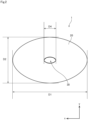
- Fig. 2 is a top view of the organ container 1.
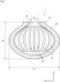
- Fig. 3 is a sectional view of the organ container 1.
- This organ container 1 is a container for temporarily accommodating an organ removed from a donor in a transplant operation for transplanting the organ into the recipient. That is, the organ container 1 is a medical appliance for use in organ transplant operations.
- organ container 1 examples include a kidney, a heart, and a lung. Blood vessels of these organs that are to be anastomosed in transplant operations are concentrated on one side of the organs.
- the structure of the organ container 1 according to the present embodiment is particularly suitable for these organs.
- the organ container according to the present invention may be configured to accommodate other organs such as a liver.
- the up-down direction is defined such that the side of the organ container 1 with an opening 30 is considered as the upper side and the bottom side of the organ container 1 opposite to the opening 30 is considered as the lower side.
- the up-down direction is also referred to as a z direction
- a direction along the long sides of the organ container 1 when viewed in the z direction is referred to as an x direction
- a direction along the short sides of the organ container 1 when viewed in the z direction is referred to as a y direction, as illustrated in Fig. 1 .
- the definition of the up-down direction does not intend to limit the orientation of the organ container 1 during use.
- the organ container 1 includes a pouch-shaped body 20 with contraction and expansion properties.
- the body 20 has an opening 30 and a thick part 40.
- the opening 30 communicates between the inside of the body 20 and an exterior space.
- the thick part 40 surrounds the opening 30 in a ring shape.
- the organ container 1 according to the present embodiment as a whole is generally an ellipsoid. That is, the body 20 has generally an ellipsoidal shape. This organ container 1 is, in particular, configured to accommodate a kidney.
- the organ container 1 as a whole is made in generally an ellipsoidal shape so that the inner surface of the body 20 has a shape that easily fits along the surface of a kidney.
- a length of the body 20 in the direction along the long sides (x direction) is referred to as a length D1
- a length of the body 20 in the direction along the short sides (y direction) is referred to as a length D2
- a length of the body 20 in the up-down direction (z direction) is referred to as a length D3, as illustrated in Figs. 2 and 3 .
- the body 20 is formed of an elastomer gel. Specifically, the body 20 is formed of a thermoplastic elastomer, an urethane elastomer, or an oil bleeding silicone gel.
- the body 20 has a hardness of, for example, E10 to A10 according to a durometer hardness test that complies with Japanese Industrial Standards JIS K 6253-3:2012. An elongation percentage at break for the body 20 is higher than or equal to 1000%.
- Forming the body 20 of such a material makes the body 20 and the opening 30 easy to expand and less likely to break. Forming the body 20 of such a material also makes it possible to reduce the possibility that the temperature outside the body 20 propagates to the organ in the body 20 at the time of accommodating the organ in the body 20.
- the opening 30 is an opening for inserting an organ into the internal space of the body 20.
- the opening 30 also plays a role as a connection port for connecting blood vessels or other pathways connected to the organ to the outside while the organ is accommodated in the body 20.
- the opening 30 has an elliptical shape.
- a length of the opening 30 along the major axis is referred to as a length D4.
- the length D4 which is a maximum width of the opening 30 in a no-load condition, is shorter than the length D1, which is a maximum width of the body 20.
- the thick part 40 is a partial area that is greater in thickness than the surrounding area.
- the elastomer gel which forms the body 20
- surrounding the opening 30 in a ring shape by the thick part 40 makes it possible to increase an elastically deformable amount of the area around the opening 30 and to improve strength around the opening 30. That is, it is possible, at the time of expanding the opening 30, to suppress plastic deformation around the opening 30 and breakage of the opening 30.
- the thick part 40 comes in intimate contact with the organ. This suppresses a protrusion of the organ from the opening 30 and suppresses an outflow of a liquid held between the organ and the body 20 from the opening 30.
- the inner surface of the body 20 has an uneven shape. Specifically, as illustrated in Fig. 3 , the inner surface of the body 20 has a plurality of projections 41 that project toward the internal space of the body 20. The projections 41 extend in the up-down direction from the opening 30 toward the bottom of the body 20. Accordingly, a groove 50 is formed between each pair of adjacent projections 41. That is, the inner surface of the body 20 has a plurality of grooves 50 extending in the up-down direction.
- This uneven inner surface of the body 20 allows a preservation solution for cooling to be held in the interstices between the organ and depressions in the inner surface of the body 20 when the organ is accommodated in the body 20.
- the preservation solution for cooling poured inside from the opening 30 can easily reach the bottom side. That is, the preservation solution for cooling, held between the organ and the inner surface of the body 20, is likely to spread across the inner surface.
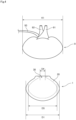
- Figs. 4 to 6 are diagrams illustrating how a kidney 9, which is one example of the organ, is accommodated in the organ container 1.
- Fig. 4 is a diagram illustrating the kidney 9 and the organ container 1 that is in a no-load condition side by side.
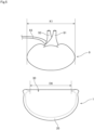
- Fig. 5 is a diagram illustrating that the opening 30 of the organ container 1 is expanded in order to accommodate the kidney 9.
- Fig. 6 is a diagram illustrating that the kidney 9 is accommodated in the organ container 1.
- the length D1 which is the maximum width of the body 20 of the organ container 1 is shorter than a maximum width of the kidney 9, i.e., a length K1. That is, in a no-load condition, a maximum width of the inner surface of the body 20, i.e., a length D5, is shorter than the length K1, which is the maximum width of the kidney 9.
- the length D4 which is the maximum width of the opening 30 in a no-load condition, is shorter than the length K1, which is the maximum width of the kidney 9.
- the opening 30 is expandable to a state in which the maximum width of the opening 30 becomes greater than the length D1, which is the maximum width of the body 20 in a no-load condition.
- the kidney 9 can be easily accommodated in the body 20.
- Fig. 5 a state is illustrated in which the opening 30 is expanded until the maximum width of the opening 30 becomes a length D6 longer than the length D1. In this way, the operator expands the opening 30 to accommodate the kidney 9 in the body 20 through the opening 30.
- the opening 30 can be expanded to a state in which the maximum width of the opening 30 becomes greater than the length K1, which is the maximum width of the kidney 9. Therefore, the kidney 9 can be more easily accommodated in the body 20.
- the kidney 9 when the kidney 9 is accommodated in the body 20 as illustrated in Fig. 6 , the entire inner surface of the body 20 including the periphery of the opening 30 fits along the surface of the kidney 9. As described above, in a no-load condition, the inner surface of the body 20 is smaller than the outer surface of the kidney 9. Thus, when the kidney 9 is accommodated in the organ container 1, the inner surface of the body 20 fits along the outer surface of the kidney 9, and the projections 41 on the inner surface of the body 20 come in intimate contact with the outer surface of the kidney 9. Accordingly, the kidney 9 is appropriately held without being moved inside the body 20. As a result, it is possible to suppress damage to the kidney 9.
- FIG. 7 is a flowchart illustrating the procedure for the transplant operation using the organ container 1. The following description is given of the case where the kidney 9 is to be transplanted using the organ container 1.
- the kidney 9 is removed from a donor (step S1). Specifically, blood vessels 91 and 92 and an ureter 93 that extend from the kidney 9 of the donor (see Figs. 4 to 6 ) are cut, and the kidney 9 is taken out of the body cavity of the donor.
- the removed kidney 9 is preserved while being immersed in a low-temperature preservation solution.
- the kidney 9 is also accommodated in the organ container 1 (step S2).
- saline kept at 4°C is used as the preservation solution. If the organ is left at ordinary temperature and the bloodstream in the organ is stopped, i.e., the organ gets into a so-called warm ischemic state, the organ becomes easy to deteriorate due to metabolism in the organ.
- the kidney 9 is preserved at a temperature lower than ordinary temperature so as to suppress deterioration of the kidney 9.
- tubes may be connected to the blood vessels 91 and 92 of the kidney 9, and the kidney 9 may be preserved while being perfused with a preservation solution. Note that the perfusion using the preservation solution may continue until step S4 described later.
- the timing when the kidney 9 is accommodated in the organ container 1 may be before the kidney 9 is immersed in the preservation solution, or may be after the kidney 9 is immersed in the preservation solution for a while and sufficiently cooled.
- the opening 30 of the organ container 1 is opened, and the kidney 9 is inserted through the opening 30 into the body 20 as illustrated in Fig. 5 . Accordingly, the kidney 9 is held inside the pouch-shaped body 20 as illustrated in Fig. 6 .
- a low-temperature preservation solution is poured into the space between the kidney 9 and the inner surface of the body 20, using a syringe or a pipette.
- the kidney 9 embraced by the organ container 1 is immersed again in a low-temperature preservation solution to maintain a low-temperature preservation condition.
- the kidney 9 held by the organ container 1 is transported from the donor side to the recipient side while being immersed in the low-temperature preservation solution (step S3).
- the kidney 9 transported to the recipient side continues to be held by the organ container 1 and to be immersed in the low-temperature preservation solution until just before transplantation.
- the abdomen of the recipient is opened, and the organ container 1 accommodating the kidney 9 therein is placed in the body cavity of the recipient (step S4).
- the blood vessels of the recipient are anastomosed to the blood vessels 91 and 92 of the kidney 9 exposed to the outside through the opening 30 of the organ container 1 (step S5).
- the ureter 93 is also connected to the urinary bladder.
- the kidney 9 accommodated in the organ container 1 is placed within the body cavity.
- the organ container 1 has a thermal insulating function, it is possible to suppress a temperature rise in the kidney 9 due to the body temperature of the recipient or the outside air temperature. This reduces the possibility that the kidney 9 gets into a warm ischemic state and its deterioration progresses due to metabolism. As a result, it is possible to suppress the occurrence of troubles after operation.
- a low-temperature preservation solution is poured at regular time intervals into the organ container 1, using a syringe or a pipette. For example, a low-temperature preservation solution is poured every few minutes into the organ container 1. This further suppresses a temperature rise in the kidney 9.
- the opening 30 of the organ container 1 is opened, and the kidney 9 that has undergone vascular anastomosis is taken out of the organ container 1. Then, the organ container 1 is removed from the body cavity of the recipient (step S6). Thereafter, the bloodstream from the anastomosed blood vessels of the recipient to the kidney 9 is resumed (step S7).
- This organ container 1 covers the surface of the kidney 9 along the surface of the kidney 9. Thus, part of the organ container 1 does not expand around the kidney 9. For example, end sections or the like of the organ container 1 do not expand around the kidney 9. Accordingly, the organ container 1 is less likely to hinder work during operation. Moreover, the organ container 1 covers most part of the surface of the kidney 9 and thereby further suppresses a temperature rise in the kidney 9 and prevents damage to the surface of the kidney 9 during operation.
- This organ container 1 is formed of a raw material having elasticity. Thus, the organ container 1 can absorb impacts on the kidney 9 during transport or during operation. Accordingly, it is possible to suppress damage to the kidney 9.
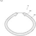
- Fig. 8 is a sectional view of an organ container 1A according to a variation.
- Fig. 9 is a sectional view of an organ container 1B according to another variation. In Figs. 8 and 9 , uneven shapes of the inner surfaces of bodies 20A and 20B are not illustrated.
- the thick part 40 is greater in thickness than the surrounding area as a result of protruding toward the outer surface of the body 20 without protruding toward the inner surface of the body 20.
- a thick part 40A has a generally circular sectional shape.
- the thick part 40A protrudes toward both of the inner and outer surfaces of the body 20A.
- a thick part 40B protrudes toward the inner surface of the body 20B without protruding toward the outer surface of the body 20B.
- the thick part may protrude toward both of the inner and outer surfaces of the body.
- the shape of the thick part may be appropriately changed.
- Fig. 10 is a sectional view of an organ container 1C according to another variation. As in Figs. 8 and 9 , an uneven shape of the inner surface of the body 20C is not illustrated in Fig. 10 .
- the organ container 1 according to the above-described embodiment includes one opening 30 and is thus suitable for organs such as a kidney, a heart, or a lung in which blood vessels to be anastomosed during transplant operations are concentrated on one side of the organs.
- a body 20C of the organ container 1C in the example illustrated in Fig. 10 has two openings 30C.
- the organ container 1C is suitable for organs such as a liver, a pancreas, or a spleen in which blood vessels to be anastomosed during transplant operations extend in multiple directions.
- the number of openings in the body is not limited to one. In the case where the body has a plurality of openings, these openings do not necessarily have to be of the same size.
- An opening through which a blood vessel passes may be smaller than an opening for accommodating an organ.
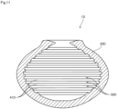
- Fig. 11 is a sectional view of an organ container 1D according to another variation.
- the inner surface of a body 20D has a plurality of projections 41D that extend in a direction orthogonal to the up-down direction. Accordingly, a groove 50D is formed between each pair of adjacent projections 41D. That is, the inner surface of the body 20D has a plurality of grooves 50D extending in the direction orthogonal to the up-down direction.
- the grooves formed in the inner surface of the body extend in the up-down direction, but the present invention is not limited thereto.
- the direction of extension of the grooves may be a direction orthogonal to the up-down direction as in the example illustrated in Fig. 11 .
- the grooves may be formed in, for example, a spiral shape in the inner surface of the body.
- the grooves include a plurality of first grooves that extend generally parallel to one another in a predetermined direction, and a plurality of second grooves that extend generally parallel to one another in a predetermined direction different from the direction of extension of the first grooves, and at least some of the first grooves and at least some of the second grooves intersect with one another in lattice form.
- the uneven shape of the inner surface of the body is not limited to projections and grooves, both extending in a predetermined direction.
- the inner surface of the body may have projections or depressions of indefinite shape that are arranged at random intervals.
- the body 20 of the organ container 1 is formed of a single type of material, but the present invention is not limited thereto.
- the body 20 may be configured of a plurality of layers formed of different materials.
- a layer that is close to the outer surface of the body may have a greater durometer hardness value than a layer that forms the inner surface of the body that comes in contact with an organ.
- a coating may be applied to the outer surface of the body in order to prevent external damage.
- a detailed structure of the organ container does not necessarily have to match completely with the structure illustrated in each drawing of the present application.
- Each component given in the embodiment and variations described above may be combined appropriately within a range that causes no contradictions.
- a first aspect of the invention is an organ container (1) for accommodating an organ, comprising:
- a second aspect of the invention is the organ container (1) according to the first aspect, wherein said body (20) has a ring-shaped thick part (40) that surrounds said opening (30).
- a third aspect of the invention is the organ container (1) according to the first or second aspect, wherein said body has an inner surface of an uneven shape.
- a fourth aspect of the invention is the organ container (1) according to the first or second aspect, wherein said body (20) has an inner surface having a plurality of grooves (50).
- a fifth aspect of the invention is the organ container (1) according to the fourth aspect, wherein said plurality of grooves (50) includes:
- a six aspect of the invention is the organ container (1) according to any one of the first to fifth aspect, wherein said body (20) has generally an ellipsoidal shape.
- a seventh aspect of the invention is the organ container (1) according to any one of the first to sixth aspect, wherein said body (20) has a hardness of E10 to A10 according to a durometer hardness test that complies with Japanese Industrial Standards JIS K 6253-3:2012.
- An eighth aspect of the invention is the organ container (1) according to any one of the first to seventh aspect, wherein said body (20) is formed of an elastomer gel.
- a ninth aspect of the invention is the organ container (1) according to the eighth aspect, wherein said body (20) is formed of a thermoplastic elastomer, an urethane elastomer, or an oil bleeding silicone gel.
- a tenth aspect of the invention is the organ container (1) according to any one of the first to ninth aspect, wherein said opening (30) is expandable to a state in which the maximum width of said opening (30) becomes greater than the maximum width of said organ.
- An eleventh aspect of the invention is the organ container (1) according to any one of the first to tenth aspect, wherein in a no-load condition, a maximum width of an inner surface of said body (20) is less than a maximum width of said organ.
Landscapes
- Life Sciences & Earth Sciences (AREA)
- Health & Medical Sciences (AREA)
- General Health & Medical Sciences (AREA)
- Engineering & Computer Science (AREA)
- Environmental Sciences (AREA)
- Zoology (AREA)
- Wood Science & Technology (AREA)
- Dentistry (AREA)
- Biomedical Technology (AREA)
- Animal Behavior & Ethology (AREA)
- Public Health (AREA)
- Veterinary Medicine (AREA)
- Vascular Medicine (AREA)
- Heart & Thoracic Surgery (AREA)
- Physics & Mathematics (AREA)
- Thermal Sciences (AREA)
- Agricultural Chemicals And Associated Chemicals (AREA)
- Medical Preparation Storing Or Oral Administration Devices (AREA)
- Wrappers (AREA)
Abstract
Description
- The present invention relates to an organ container for accommodating an organ.
- In organ transplant operations, an organ removed from a donor is preserved under cooled conditions. This is because if the organ is left at ordinary temperature and the bloodstream in the organ is stopped, i.e., the organ gets into a so-called warm ischemic state, the organ becomes easy to deteriorate due to metabolism in the organ. Specifically, the temperature of the organ is kept low through procedures such as pouring a low-temperature preservation solution into the isolated organ or directly spraying ice-slush saline around the organ. This suppresses organ metabolism.
- However, at the time of transplanting an organ into a recipient, the organ is placed in the body cavity of the recipient and undergoes procedures such as vascular anastomosis. At this time, the organ cannot be kept under cooled conditions, so that the temperature of the organ rises due to the body temperature of the recipient or the outside air temperature and the organ gradually gets into a warm ischemic state. Hence, the surgeon carrying out the transplant operation has to maintain low-temperature conditions of the organ to be transplanted, by, for example, performing procedures such as vascular anastomosis in a time as short as possible or pouring ice or other materials into the abdominal cavity. In the latter case, not only the organ but also the fingertips of the surgeon will be cooled at the same time, and this is disadvantageous for vascular anastomosis that requires high precision.
- In view of this, the inventors of the present application have proposed a technique described in
Japanese Patent Application Laid-Open No. 2018-000309 Japanese Patent Application Laid-Open No. 2018-000309 - However, the sheet according to
Japanese Patent Application Laid-Open No. 2018-000309 - It is an object of the present invention to provide a medical appliance that further suppresses a temperature rise in an organ and is less likely to hinder the work of a surgeon at the time of transplanting the organ into a recipient.
- In order to solve the above-described problem, a first aspect of the present application is an organ container for accommodating an organ. The organ container includes a pouch-shaped body having contraction and expansion properties and an opening. In a no-load condition, a maximum width of the opening is less than a maximum width of the body. The opening is expandable to a state in which the maximum width of the opening becomes greater than the maximum width of the body.
- According to the first aspect of the present application, the organ container covers the surface of an organ along the surface of the organ. Thus, when the organ is placed in the body cavity of the recipient, the organ container does not expand around the organ. Accordingly, the organ container is less likely to hinder work during operation. Moreover, the organ container covers most part of the organ and thereby suppresses a temperature rise in the organ.
- These and other objects, features, aspects and advantages of the present invention will become more apparent from the following detailed description of the present invention when taken in conjunction with the accompanying drawings.
-
-
Fig. 1 is a perspective view of an organ container; -
Fig. 2 is a top view of the organ container; -
Fig. 3 is a sectional view of the organ container; -
Fig. 4 is a diagram illustrating how an organ is accommodated in the organ container; -
Fig. 5 is a diagram illustrating how the organ is accommodated in the organ container; -
Fig. 6 is a diagram illustrating how the organ is accommodated in the organ container; -
Fig. 7 is a flowchart of a procedure for a transplant operation using the organ container; -
Fig. 8 is a sectional view of an organ container according to a variation; -
Fig. 9 is a sectional view of an organ container according to another variation; -
Fig. 10 is a sectional view of an organ container according to another variation; and -
Fig. 11 is a sectional view of an organ container according to another variation. - An embodiment of the present invention will be described hereinafter with reference to the drawings.
- In the present application, "donors" and "recipients" may be humans, or may be non-human animals. That is, "organs" according to the present application may be human organs, or may be organs of non-human animals. The non-human animals may be rodents such as mice and rats, ungulates such as pigs, goats, and sheep, non-human primates such as chimpanzees, or other non-human mammals, or may be nonmammalian animals.
-
Fig. 1 is a perspective view of anorgan container 1 according to a first embodiment.Fig. 2 is a top view of theorgan container 1.Fig. 3 is a sectional view of theorgan container 1. Thisorgan container 1 is a container for temporarily accommodating an organ removed from a donor in a transplant operation for transplanting the organ into the recipient. That is, theorgan container 1 is a medical appliance for use in organ transplant operations. - Examples of the organ that can be accommodated in the
organ container 1 include a kidney, a heart, and a lung. Blood vessels of these organs that are to be anastomosed in transplant operations are concentrated on one side of the organs. The structure of theorgan container 1 according to the present embodiment is particularly suitable for these organs. However, the organ container according to the present invention may be configured to accommodate other organs such as a liver. - In the following description, the up-down direction is defined such that the side of the
organ container 1 with anopening 30 is considered as the upper side and the bottom side of theorgan container 1 opposite to theopening 30 is considered as the lower side. In the following description, the up-down direction is also referred to as a z direction, a direction along the long sides of theorgan container 1 when viewed in the z direction is referred to as an x direction, and a direction along the short sides of theorgan container 1 when viewed in the z direction is referred to as a y direction, as illustrated inFig. 1 . Note that the definition of the up-down direction does not intend to limit the orientation of theorgan container 1 during use. - As illustrated in
Fig. 1 , theorgan container 1 includes a pouch-shaped body 20 with contraction and expansion properties. Thebody 20 has an opening 30 and athick part 40. The opening 30 communicates between the inside of thebody 20 and an exterior space. Thethick part 40 surrounds the opening 30 in a ring shape. - The
organ container 1 according to the present embodiment as a whole is generally an ellipsoid. That is, thebody 20 has generally an ellipsoidal shape. Thisorgan container 1 is, in particular, configured to accommodate a kidney. Theorgan container 1 as a whole is made in generally an ellipsoidal shape so that the inner surface of thebody 20 has a shape that easily fits along the surface of a kidney. - To describe the relation of dimensions, in the following description, a length of the
body 20 in the direction along the long sides (x direction) is referred to as a length D1, a length of thebody 20 in the direction along the short sides (y direction) is referred to as a length D2, and a length of thebody 20 in the up-down direction (z direction) is referred to as a length D3, as illustrated inFigs. 2 and3 . - The
body 20 is formed of an elastomer gel. Specifically, thebody 20 is formed of a thermoplastic elastomer, an urethane elastomer, or an oil bleeding silicone gel. Thebody 20 has a hardness of, for example, E10 to A10 according to a durometer hardness test that complies with Japanese Industrial Standards JIS K 6253-3:2012. An elongation percentage at break for thebody 20 is higher than or equal to 1000%. - Forming the
body 20 of such a material makes thebody 20 and theopening 30 easy to expand and less likely to break. Forming thebody 20 of such a material also makes it possible to reduce the possibility that the temperature outside thebody 20 propagates to the organ in thebody 20 at the time of accommodating the organ in thebody 20. - The
opening 30 is an opening for inserting an organ into the internal space of thebody 20. Theopening 30 also plays a role as a connection port for connecting blood vessels or other pathways connected to the organ to the outside while the organ is accommodated in thebody 20. - In the present embodiment, the
opening 30 has an elliptical shape. In a no-load condition in which no artificial loads are imposed on theorgan container 1, a length of theopening 30 along the major axis is referred to as a length D4. The length D4, which is a maximum width of theopening 30 in a no-load condition, is shorter than the length D1, which is a maximum width of thebody 20. - The
thick part 40 is a partial area that is greater in thickness than the surrounding area. With increasing thickness, the elastomer gel, which forms thebody 20, has a higher capability to contract in a direction returning to its original state against loads applied in the direction of expansion. Thus, surrounding theopening 30 in a ring shape by thethick part 40 makes it possible to increase an elastically deformable amount of the area around theopening 30 and to improve strength around theopening 30. That is, it is possible, at the time of expanding theopening 30, to suppress plastic deformation around theopening 30 and breakage of theopening 30. - Besides, at the time of accommodating the organ inside, the
thick part 40 comes in intimate contact with the organ. This suppresses a protrusion of the organ from theopening 30 and suppresses an outflow of a liquid held between the organ and thebody 20 from theopening 30. - The inner surface of the
body 20 has an uneven shape. Specifically, as illustrated inFig. 3 , the inner surface of thebody 20 has a plurality ofprojections 41 that project toward the internal space of thebody 20. Theprojections 41 extend in the up-down direction from theopening 30 toward the bottom of thebody 20. Accordingly, agroove 50 is formed between each pair ofadjacent projections 41. That is, the inner surface of thebody 20 has a plurality ofgrooves 50 extending in the up-down direction. - This uneven inner surface of the
body 20 allows a preservation solution for cooling to be held in the interstices between the organ and depressions in the inner surface of thebody 20 when the organ is accommodated in thebody 20. In particular, in the case where the inner surface of thebody 20 has a plurality ofgrooves 50 extending in the up-down direction as in the present embodiment, the preservation solution for cooling poured inside from theopening 30 can easily reach the bottom side. That is, the preservation solution for cooling, held between the organ and the inner surface of thebody 20, is likely to spread across the inner surface. -
Figs. 4 to 6 are diagrams illustrating how akidney 9, which is one example of the organ, is accommodated in theorgan container 1. Specifically,Fig. 4 is a diagram illustrating thekidney 9 and theorgan container 1 that is in a no-load condition side by side.Fig. 5 is a diagram illustrating that theopening 30 of theorgan container 1 is expanded in order to accommodate thekidney 9.Fig. 6 is a diagram illustrating that thekidney 9 is accommodated in theorgan container 1. - As illustrated in
Fig. 4 , in a no-load condition, the length D1, which is the maximum width of thebody 20 of theorgan container 1, is shorter than a maximum width of thekidney 9, i.e., a length K1. That is, in a no-load condition, a maximum width of the inner surface of thebody 20, i.e., a length D5, is shorter than the length K1, which is the maximum width of thekidney 9. Thus, the length D4, which is the maximum width of theopening 30 in a no-load condition, is shorter than the length K1, which is the maximum width of thekidney 9. - The
opening 30 is expandable to a state in which the maximum width of theopening 30 becomes greater than the length D1, which is the maximum width of thebody 20 in a no-load condition. Thus, thekidney 9 can be easily accommodated in thebody 20. InFig. 5 , a state is illustrated in which theopening 30 is expanded until the maximum width of theopening 30 becomes a length D6 longer than the length D1. In this way, the operator expands theopening 30 to accommodate thekidney 9 in thebody 20 through theopening 30. In theorgan container 1 according to the present embodiment, theopening 30 can be expanded to a state in which the maximum width of theopening 30 becomes greater than the length K1, which is the maximum width of thekidney 9. Therefore, thekidney 9 can be more easily accommodated in thebody 20. - Then, when the
kidney 9 is accommodated in thebody 20 as illustrated inFig. 6 , the entire inner surface of thebody 20 including the periphery of theopening 30 fits along the surface of thekidney 9. As described above, in a no-load condition, the inner surface of thebody 20 is smaller than the outer surface of thekidney 9. Thus, when thekidney 9 is accommodated in theorgan container 1, the inner surface of thebody 20 fits along the outer surface of thekidney 9, and theprojections 41 on the inner surface of thebody 20 come in intimate contact with the outer surface of thekidney 9. Accordingly, thekidney 9 is appropriately held without being moved inside thebody 20. As a result, it is possible to suppress damage to thekidney 9. - Next, a procedure for a transplant operation using the above-described
organ container 1 will be described.Fig. 7 is a flowchart illustrating the procedure for the transplant operation using theorgan container 1. The following description is given of the case where thekidney 9 is to be transplanted using theorgan container 1. - In the transplant operation, first the
kidney 9 is removed from a donor (step S1). Specifically,blood vessels ureter 93 that extend from thekidney 9 of the donor (seeFigs. 4 to 6 ) are cut, and thekidney 9 is taken out of the body cavity of the donor. - The removed
kidney 9 is preserved while being immersed in a low-temperature preservation solution. Thekidney 9 is also accommodated in the organ container 1 (step S2). For example, saline kept at 4°C is used as the preservation solution. If the organ is left at ordinary temperature and the bloodstream in the organ is stopped, i.e., the organ gets into a so-called warm ischemic state, the organ becomes easy to deteriorate due to metabolism in the organ. Thus, in step S2, thekidney 9 is preserved at a temperature lower than ordinary temperature so as to suppress deterioration of thekidney 9. - Alternatively, in step S2, tubes may be connected to the
blood vessels kidney 9, and thekidney 9 may be preserved while being perfused with a preservation solution. Note that the perfusion using the preservation solution may continue until step S4 described later. - The timing when the
kidney 9 is accommodated in theorgan container 1 may be before thekidney 9 is immersed in the preservation solution, or may be after thekidney 9 is immersed in the preservation solution for a while and sufficiently cooled. When thekidney 9 is accommodated in theorgan container 1, theopening 30 of theorgan container 1 is opened, and thekidney 9 is inserted through theopening 30 into thebody 20 as illustrated inFig. 5 . Accordingly, thekidney 9 is held inside the pouch-shapedbody 20 as illustrated inFig. 6 . At this time, a low-temperature preservation solution is poured into the space between thekidney 9 and the inner surface of thebody 20, using a syringe or a pipette. Also, thekidney 9 embraced by theorgan container 1 is immersed again in a low-temperature preservation solution to maintain a low-temperature preservation condition. - The
kidney 9 held by theorgan container 1 is transported from the donor side to the recipient side while being immersed in the low-temperature preservation solution (step S3). Thekidney 9 transported to the recipient side continues to be held by theorgan container 1 and to be immersed in the low-temperature preservation solution until just before transplantation. - Then, the abdomen of the recipient is opened, and the
organ container 1 accommodating thekidney 9 therein is placed in the body cavity of the recipient (step S4). Then, the blood vessels of the recipient are anastomosed to theblood vessels kidney 9 exposed to the outside through theopening 30 of the organ container 1 (step S5). In the case where the organ to be transplanted is thekidney 9, theureter 93 is also connected to the urinary bladder. - During the work in steps S4 and S5, the
kidney 9 accommodated in theorgan container 1 is placed within the body cavity. At this time, since theorgan container 1 has a thermal insulating function, it is possible to suppress a temperature rise in thekidney 9 due to the body temperature of the recipient or the outside air temperature. This reduces the possibility that thekidney 9 gets into a warm ischemic state and its deterioration progresses due to metabolism. As a result, it is possible to suppress the occurrence of troubles after operation. - In steps S4 and S5, a low-temperature preservation solution is poured at regular time intervals into the
organ container 1, using a syringe or a pipette. For example, a low-temperature preservation solution is poured every few minutes into theorgan container 1. This further suppresses a temperature rise in thekidney 9. - Thereafter, the
opening 30 of theorgan container 1 is opened, and thekidney 9 that has undergone vascular anastomosis is taken out of theorgan container 1. Then, theorgan container 1 is removed from the body cavity of the recipient (step S6). Thereafter, the bloodstream from the anastomosed blood vessels of the recipient to thekidney 9 is resumed (step S7). - This
organ container 1 covers the surface of thekidney 9 along the surface of thekidney 9. Thus, part of theorgan container 1 does not expand around thekidney 9. For example, end sections or the like of theorgan container 1 do not expand around thekidney 9. Accordingly, theorgan container 1 is less likely to hinder work during operation. Moreover, theorgan container 1 covers most part of the surface of thekidney 9 and thereby further suppresses a temperature rise in thekidney 9 and prevents damage to the surface of thekidney 9 during operation. - This
organ container 1 is formed of a raw material having elasticity. Thus, theorgan container 1 can absorb impacts on thekidney 9 during transport or during operation. Accordingly, it is possible to suppress damage to thekidney 9. - While a principal embodiment of the present invention has been described thus far, the present invention is not intended to be limited to the embodiment described above.
-
Fig. 8 is a sectional view of anorgan container 1A according to a variation.Fig. 9 is a sectional view of anorgan container 1B according to another variation. InFigs. 8 and9 , uneven shapes of the inner surfaces ofbodies - In the
organ container 1 according to the above-described embodiment, thethick part 40 is greater in thickness than the surrounding area as a result of protruding toward the outer surface of thebody 20 without protruding toward the inner surface of thebody 20. In contrast, in theorgan container 1A in the example illustrated inFig. 8 , athick part 40A has a generally circular sectional shape. Thus, thethick part 40A protrudes toward both of the inner and outer surfaces of thebody 20A. In theorgan container 1B in the example illustrated inFig. 9 , athick part 40B protrudes toward the inner surface of thebody 20B without protruding toward the outer surface of thebody 20B. - As in the examples in
Figs. 8 and9 , the thick part may protrude toward both of the inner and outer surfaces of the body. The shape of the thick part may be appropriately changed. -
Fig. 10 is a sectional view of anorgan container 1C according to another variation. As inFigs. 8 and9 , an uneven shape of the inner surface of thebody 20C is not illustrated inFig. 10 . Theorgan container 1 according to the above-described embodiment includes oneopening 30 and is thus suitable for organs such as a kidney, a heart, or a lung in which blood vessels to be anastomosed during transplant operations are concentrated on one side of the organs. - In contrast, a
body 20C of theorgan container 1C in the example illustrated inFig. 10 has twoopenings 30C. Thus, theorgan container 1C is suitable for organs such as a liver, a pancreas, or a spleen in which blood vessels to be anastomosed during transplant operations extend in multiple directions. As described above, the number of openings in the body is not limited to one. In the case where the body has a plurality of openings, these openings do not necessarily have to be of the same size. An opening through which a blood vessel passes may be smaller than an opening for accommodating an organ. -
Fig. 11 is a sectional view of anorgan container 1D according to another variation. In theorgan container 1D illustrated inFig. 11 , the inner surface of abody 20D has a plurality ofprojections 41D that extend in a direction orthogonal to the up-down direction. Accordingly, agroove 50D is formed between each pair ofadjacent projections 41D. That is, the inner surface of thebody 20D has a plurality ofgrooves 50D extending in the direction orthogonal to the up-down direction. - In the above-described embodiment, the grooves formed in the inner surface of the body extend in the up-down direction, but the present invention is not limited thereto. The direction of extension of the grooves may be a direction orthogonal to the up-down direction as in the example illustrated in
Fig. 11 . - Alternatively, the grooves may be formed in, for example, a spiral shape in the inner surface of the body. As another alternative, a configuration is also possible in which the grooves include a plurality of first grooves that extend generally parallel to one another in a predetermined direction, and a plurality of second grooves that extend generally parallel to one another in a predetermined direction different from the direction of extension of the first grooves, and at least some of the first grooves and at least some of the second grooves intersect with one another in lattice form. The uneven shape of the inner surface of the body is not limited to projections and grooves, both extending in a predetermined direction. For example, the inner surface of the body may have projections or depressions of indefinite shape that are arranged at random intervals.
- In the above-described embodiment, the
body 20 of theorgan container 1 is formed of a single type of material, but the present invention is not limited thereto. For example, thebody 20 may be configured of a plurality of layers formed of different materials. For example, a layer that is close to the outer surface of the body may have a greater durometer hardness value than a layer that forms the inner surface of the body that comes in contact with an organ. Also, a coating may be applied to the outer surface of the body in order to prevent external damage. - A detailed structure of the organ container does not necessarily have to match completely with the structure illustrated in each drawing of the present application. Each component given in the embodiment and variations described above may be combined appropriately within a range that causes no contradictions.
- While the invention has been shown and described in detail, the foregoing description is in all aspects illustrative and not restrictive. It is therefore understood that numerous modifications and variations can be devised without departing from the scope of the invention.
- A first aspect of the invention is an organ container (1) for accommodating an organ, comprising:
- a pouch-shaped body (20) having contraction and expansion properties and an opening (30),
- wherein in a no-load condition, a maximum width of said opening (30) is less than a maximum width of said body (20), and
- said opening (30) is expandable to a state in which the maximum width of said opening (30) becomes greater than the maximum width of said body (20).
- A second aspect of the invention is the organ container (1) according to the first aspect, wherein
said body (20) has a ring-shaped thick part (40) that surrounds said opening (30). - A third aspect of the invention is the organ container (1) according to the first or second aspect, wherein
said body has an inner surface of an uneven shape. - A fourth aspect of the invention is the organ container (1) according to the first or second aspect, wherein
said body (20) has an inner surface having a plurality of grooves (50). - A fifth aspect of the invention is the organ container (1) according to the fourth aspect, wherein
said plurality of grooves (50) includes: - a plurality of first grooves; and
- a plurality of second grooves, each intersecting with at least some of said first grooves.
- A six aspect of the invention is the organ container (1) according to any one of the first to fifth aspect, wherein
said body (20) has generally an ellipsoidal shape. - A seventh aspect of the invention is the organ container (1) according to any one of the first to sixth aspect, wherein
said body (20) has a hardness of E10 to A10 according to a durometer hardness test that complies with Japanese Industrial Standards JIS K 6253-3:2012. - An eighth aspect of the invention is the organ container (1) according to any one of the first to seventh aspect, wherein
said body (20) is formed of an elastomer gel. - A ninth aspect of the invention is the organ container (1) according to the eighth aspect, wherein
said body (20) is formed of a thermoplastic elastomer, an urethane elastomer, or an oil bleeding silicone gel. - A tenth aspect of the invention is the organ container (1) according to any one of the first to ninth aspect, wherein
said opening (30) is expandable to a state in which the maximum width of said opening (30) becomes greater than the maximum width of said organ. - An eleventh aspect of the invention is the organ container (1) according to any one of the first to tenth aspect, wherein
in a no-load condition, a maximum width of an inner surface of said body (20) is less than a maximum width of said organ.
Claims (10)
- An organ container (1) for accommodating an organ, comprising:an expandable pouch-shaped body (20), which is formed of an elastomer gel, having an opening (30),wherein in a no-load condition, a maximum width of said opening (30) is less than a maximum width of said body (20), characterized in thatsaid opening (30) is expandable to a state in which the maximum width of said opening (30) becomes greater than the maximum width of said body (20) in a no-load condition.
- The organ container (1) according to claim 1, whereinsaid body (20) has a ring-shaped thick part (40) that surrounds said opening (30),said thick part (40) is a partial area that is greater in thickness than the surrounding area such that said thick part (40) is adapted to increase an elastically deformable amount of the area around the opening (30).
- The organ container (1) according to claim 1 or 2, wherein
said body has an inner surface of an uneven shape. - The organ container (1) according to claim 1 or 2, wherein
an inner surface of the body (20) has a plurality of grooves (50). - The organ container (1) according to claim 4, wherein
said plurality of grooves (50) includes:a plurality of first grooves; anda plurality of second grooves, each intersecting with at least some of said first grooves. - The organ container (1) according to any one of claims 1 to 5, wherein
said body (20) has generally an ellipsoidal shape. - The organ container (1) according to any one of claims 1 to 6, wherein
said body (20) has a hardness of E10 to A10 according to a durometer hardness test that complies with Japanese Industrial Standards JIS K 6253-3:2012. - The organ container (1) according to any one of claims 1 to 7, wherein
said body (20) is formed of a thermoplastic elastomer, an urethane elastomer, or an oil bleeding silicone gel. - The organ container (1) according to any one of claims 1 to 8, wherein
said opening (30) is expandable to a state in which the maximum width of said opening (30) becomes greater than the maximum width of said organ, said organ is a kidney, a heart, a lung or a liver [0011]. - The organ container (1) according to any one of claims 1 to 9, wherein
in a no-load condition, a maximum width of an inner surface of said body (20) is less than a maximum width of said organ.
Applications Claiming Priority (2)
| Application Number | Priority Date | Filing Date | Title |
|---|---|---|---|
| JP2019165110A JP7355567B2 (en) | 2019-09-11 | 2019-09-11 | organ storage container |
| EP20194973.2A EP3791720B1 (en) | 2019-09-11 | 2020-09-08 | Organ container |
Related Parent Applications (2)
| Application Number | Title | Priority Date | Filing Date |
|---|---|---|---|
| EP20194973.2A Division-Into EP3791720B1 (en) | 2019-09-11 | 2020-09-08 | Organ container |
| EP20194973.2A Division EP3791720B1 (en) | 2019-09-11 | 2020-09-08 | Organ container |
Publications (2)
| Publication Number | Publication Date |
|---|---|
| EP4501291A2 true EP4501291A2 (en) | 2025-02-05 |
| EP4501291A3 EP4501291A3 (en) | 2025-04-02 |
Family
ID=72428214
Family Applications (2)
| Application Number | Title | Priority Date | Filing Date |
|---|---|---|---|
| EP24215178.5A Pending EP4501291A3 (en) | 2019-09-11 | 2020-09-08 | Organ container |
| EP20194973.2A Active EP3791720B1 (en) | 2019-09-11 | 2020-09-08 | Organ container |
Family Applications After (1)
| Application Number | Title | Priority Date | Filing Date |
|---|---|---|---|
| EP20194973.2A Active EP3791720B1 (en) | 2019-09-11 | 2020-09-08 | Organ container |
Country Status (4)
| Country | Link |
|---|---|
| US (2) | US20210106002A1 (en) |
| EP (2) | EP4501291A3 (en) |
| JP (2) | JP7355567B2 (en) |
| CN (2) | CN115968866A (en) |
Families Citing this family (5)
| Publication number | Priority date | Publication date | Assignee | Title |
|---|---|---|---|---|
| US20220346370A1 (en) * | 2019-08-15 | 2022-11-03 | Iishield Pty Ltd | An insulating medical device for protecting a graft for transplant |
| JP7406394B2 (en) * | 2020-02-14 | 2023-12-27 | 株式会社Screenホールディングス | organ storage container |
| JP7431096B2 (en) * | 2020-04-14 | 2024-02-14 | 株式会社Screenホールディングス | organ storage container |
| JP7538668B2 (en) * | 2020-09-17 | 2024-08-22 | 株式会社Screenホールディングス | Organ container |
| WO2025012247A1 (en) * | 2023-07-11 | 2025-01-16 | Rijksuniversiteit Groningen | Lung storage device and method for using the same |
Citations (1)
| Publication number | Priority date | Publication date | Assignee | Title |
|---|---|---|---|---|
| JP2018000309A (en) | 2016-06-28 | 2018-01-11 | 株式会社Screenホールディングス | Internal organ protecting sheet |
Family Cites Families (13)
| Publication number | Priority date | Publication date | Assignee | Title |
|---|---|---|---|---|
| JPH07101802A (en) * | 1993-10-01 | 1995-04-18 | Kohei Hasegawa | Accommodation of encleated organ |
| JP2004075583A (en) * | 2002-08-13 | 2004-03-11 | Senko Medical Instr Mfg Co Ltd | Organ preservation device |
| JP2006141536A (en) | 2004-11-17 | 2006-06-08 | Morita Mfg Co Ltd | Isolated organ storage bag |
| WO2009099165A1 (en) | 2008-02-08 | 2009-08-13 | Kyoto University | Therapeutic device for chronic obstructive pulmonary disease |
| CN202907693U (en) * | 2012-10-22 | 2013-05-01 | 同济大学附属上海市肺科医院 | Device for low-temperature sequential ventilation preservation of lungs in NHBD (non heart heating donor) lung transplantation |
| US10076112B2 (en) * | 2014-06-02 | 2018-09-18 | Transmedic, Inc. | Ex vivo organ care system |
| WO2017189442A1 (en) * | 2016-04-25 | 2017-11-02 | Claria Medical, Inc. | Systems and methods for tissue capture and removal |
| CN105852982A (en) | 2016-05-04 | 2016-08-17 | 宜兴市人民医院 | Special surgical plastic container for protecting visceral organs |
| CN206851880U (en) | 2017-06-01 | 2018-01-09 | 中国人民解放军第三〇九医院 | Organoprotective device for transfer operation |
| JP6967434B2 (en) | 2017-11-28 | 2021-11-17 | 株式会社Screenホールディングス | Organ container |
| CN107969419A (en) | 2017-12-20 | 2018-05-01 | 中国人民解放军第二军医大学第二附属医院 | Low temperature protection renal bag and its application method are used in a kind of art |
| CN207604426U (en) * | 2017-12-20 | 2018-07-13 | 中国人民解放军第二军医大学第二附属医院 | Low temperature protection renal bag is used in a kind of art |
| JP7143167B2 (en) * | 2018-09-21 | 2022-09-28 | 株式会社Screenホールディングス | Organ-receiving bag and transplantation method |
-
2019
- 2019-09-11 JP JP2019165110A patent/JP7355567B2/en active Active
-
2020
- 2020-09-08 EP EP24215178.5A patent/EP4501291A3/en active Pending
- 2020-09-08 EP EP20194973.2A patent/EP3791720B1/en active Active
- 2020-09-10 US US17/017,134 patent/US20210106002A1/en not_active Abandoned
- 2020-09-10 CN CN202310051815.1A patent/CN115968866A/en active Pending
- 2020-09-10 CN CN202010948072.4A patent/CN112471133A/en active Pending
-
2023
- 2023-03-08 US US18/180,538 patent/US20230217918A1/en not_active Abandoned
- 2023-09-21 JP JP2023155572A patent/JP7592811B2/en active Active
Patent Citations (1)
| Publication number | Priority date | Publication date | Assignee | Title |
|---|---|---|---|---|
| JP2018000309A (en) | 2016-06-28 | 2018-01-11 | 株式会社Screenホールディングス | Internal organ protecting sheet |
Also Published As
| Publication number | Publication date |
|---|---|
| EP3791720B1 (en) | 2025-01-22 |
| CN115968866A (en) | 2023-04-18 |
| EP3791720A1 (en) | 2021-03-17 |
| US20210106002A1 (en) | 2021-04-15 |
| EP4501291A3 (en) | 2025-04-02 |
| JP2021040938A (en) | 2021-03-18 |
| JP7592811B2 (en) | 2024-12-02 |
| JP2023165814A (en) | 2023-11-17 |
| CN112471133A (en) | 2021-03-12 |
| US20230217918A1 (en) | 2023-07-13 |
| JP7355567B2 (en) | 2023-10-03 |
Similar Documents
| Publication | Publication Date | Title |
|---|---|---|
| EP3791720B1 (en) | Organ container | |
| CN109890716B (en) | Housing for flexible container | |
| EP4018827B1 (en) | Organ container | |
| KR20200055755A (en) | How to freeze liquids | |
| EP3895534A1 (en) | Organ container | |
| EP3864960B1 (en) | Organ container | |
| WO2020059413A1 (en) | Organ accommodation pouch and transplantation method | |
| EP3970487B1 (en) | Organ container | |
| JP2010098971A (en) | Container and method for preserving reproductive cell | |
| JP7266796B2 (en) | Storage containers and thawing equipment | |
| EP4399973A1 (en) | Organ storage container, organ storage device, and production method for organ storage container | |
| US20220142150A1 (en) | Packaging system for a medical product | |
| JP2022144379A (en) | Organ preservation container | |
| SU1557435A1 (en) | Method and apparatus for protecting polymeric containers from destruction in low-temperature storage | |
| JP4683357B2 (en) | Packed tofu manufacturing method | |
| JP4262118B2 (en) | Cold storage container | |
| JP2011190959A (en) | Cooling tray | |
| JP2007178039A (en) | Ice container |
Legal Events
| Date | Code | Title | Description |
|---|---|---|---|
| PUAI | Public reference made under article 153(3) epc to a published international application that has entered the european phase |
Free format text: ORIGINAL CODE: 0009012 |
|
| STAA | Information on the status of an ep patent application or granted ep patent |
Free format text: STATUS: THE APPLICATION HAS BEEN PUBLISHED |
|
| AC | Divisional application: reference to earlier application |
Ref document number: 3791720 Country of ref document: EP Kind code of ref document: P |
|
| AK | Designated contracting states |
Kind code of ref document: A2 Designated state(s): AL AT BE BG CH CY CZ DE DK EE ES FI FR GB GR HR HU IE IS IT LI LT LU LV MC MK MT NL NO PL PT RO RS SE SI SK SM TR |
|
| REG | Reference to a national code |
Ref country code: DE Ref legal event code: R079 Free format text: PREVIOUS MAIN CLASS: A61F0007100000 Ipc: A01N0001146000 |
|
| PUAL | Search report despatched |
Free format text: ORIGINAL CODE: 0009013 |
|
| AK | Designated contracting states |
Kind code of ref document: A3 Designated state(s): AL AT BE BG CH CY CZ DE DK EE ES FI FR GB GR HR HU IE IS IT LI LT LU LV MC MK MT NL NO PL PT RO RS SE SI SK SM TR |
|
| RIC1 | Information provided on ipc code assigned before grant |
Ipc: A61F 7/10 20060101ALI20250226BHEP Ipc: A01N 1/146 20250101AFI20250226BHEP |
|
| STAA | Information on the status of an ep patent application or granted ep patent |
Free format text: STATUS: REQUEST FOR EXAMINATION WAS MADE |
|
| 17P | Request for examination filed |
Effective date: 20251002 |