EP4501256A1 - Surgical treatment device - Google Patents
Surgical treatment device Download PDFInfo
- Publication number
- EP4501256A1 EP4501256A1 EP23778768.4A EP23778768A EP4501256A1 EP 4501256 A1 EP4501256 A1 EP 4501256A1 EP 23778768 A EP23778768 A EP 23778768A EP 4501256 A1 EP4501256 A1 EP 4501256A1
- Authority
- EP
- European Patent Office
- Prior art keywords
- piezoelectric element
- probe
- frequency
- resonance frequency
- ultrasound
- Prior art date
- Legal status (The legal status is an assumption and is not a legal conclusion. Google has not performed a legal analysis and makes no representation as to the accuracy of the status listed.)
- Pending
Links
Images






Classifications
-
- A—HUMAN NECESSITIES
- A61—MEDICAL OR VETERINARY SCIENCE; HYGIENE
- A61B—DIAGNOSIS; SURGERY; IDENTIFICATION
- A61B17/00—Surgical instruments, devices or methods
- A61B17/32—Surgical cutting instruments
- A61B17/320068—Surgical cutting instruments using mechanical vibrations, e.g. ultrasonic
- A61B17/320092—Surgical cutting instruments using mechanical vibrations, e.g. ultrasonic with additional movable means for clamping or cutting tissue, e.g. with a pivoting jaw
-
- A—HUMAN NECESSITIES
- A61—MEDICAL OR VETERINARY SCIENCE; HYGIENE
- A61B—DIAGNOSIS; SURGERY; IDENTIFICATION
- A61B17/00—Surgical instruments, devices or methods
- A61B17/32—Surgical cutting instruments
-
- A—HUMAN NECESSITIES
- A61—MEDICAL OR VETERINARY SCIENCE; HYGIENE
- A61B—DIAGNOSIS; SURGERY; IDENTIFICATION
- A61B17/00—Surgical instruments, devices or methods
- A61B2017/00017—Electrical control of surgical instruments
- A61B2017/00022—Sensing or detecting at the treatment site
- A61B2017/00026—Conductivity or impedance, e.g. of tissue
-
- A—HUMAN NECESSITIES
- A61—MEDICAL OR VETERINARY SCIENCE; HYGIENE
- A61B—DIAGNOSIS; SURGERY; IDENTIFICATION
- A61B17/00—Surgical instruments, devices or methods
- A61B17/00234—Surgical instruments, devices or methods for minimally invasive surgery
- A61B2017/00292—Surgical instruments, devices or methods for minimally invasive surgery mounted on or guided by flexible, e.g. catheter-like, means
- A61B2017/0034—Surgical instruments, devices or methods for minimally invasive surgery mounted on or guided by flexible, e.g. catheter-like, means adapted to be inserted through a working channel of an endoscope
-
- A—HUMAN NECESSITIES
- A61—MEDICAL OR VETERINARY SCIENCE; HYGIENE
- A61B—DIAGNOSIS; SURGERY; IDENTIFICATION
- A61B17/00—Surgical instruments, devices or methods
- A61B2017/00367—Details of actuation of instruments, e.g. relations between pushing buttons, or the like, and activation of the tool, working tip, or the like
- A61B2017/00398—Details of actuation of instruments, e.g. relations between pushing buttons, or the like, and activation of the tool, working tip, or the like using powered actuators, e.g. stepper motors, solenoids
- A61B2017/00402—Piezo electric actuators
-
- A—HUMAN NECESSITIES
- A61—MEDICAL OR VETERINARY SCIENCE; HYGIENE
- A61B—DIAGNOSIS; SURGERY; IDENTIFICATION
- A61B17/00—Surgical instruments, devices or methods
- A61B2017/00743—Type of operation; Specification of treatment sites
- A61B2017/00778—Operations on blood vessels
-
- A—HUMAN NECESSITIES
- A61—MEDICAL OR VETERINARY SCIENCE; HYGIENE
- A61B—DIAGNOSIS; SURGERY; IDENTIFICATION
- A61B17/00—Surgical instruments, devices or methods
- A61B17/32—Surgical cutting instruments
- A61B17/320068—Surgical cutting instruments using mechanical vibrations, e.g. ultrasonic
- A61B2017/320071—Surgical cutting instruments using mechanical vibrations, e.g. ultrasonic with articulating means for working tip
-
- A—HUMAN NECESSITIES
- A61—MEDICAL OR VETERINARY SCIENCE; HYGIENE
- A61B—DIAGNOSIS; SURGERY; IDENTIFICATION
- A61B17/00—Surgical instruments, devices or methods
- A61B17/32—Surgical cutting instruments
- A61B17/320068—Surgical cutting instruments using mechanical vibrations, e.g. ultrasonic
- A61B2017/320072—Working tips with special features, e.g. extending parts
- A61B2017/320073—Working tips with special features, e.g. extending parts probe
-
- A—HUMAN NECESSITIES
- A61—MEDICAL OR VETERINARY SCIENCE; HYGIENE
- A61B—DIAGNOSIS; SURGERY; IDENTIFICATION
- A61B17/00—Surgical instruments, devices or methods
- A61B17/32—Surgical cutting instruments
- A61B17/320068—Surgical cutting instruments using mechanical vibrations, e.g. ultrasonic
- A61B2017/320082—Surgical cutting instruments using mechanical vibrations, e.g. ultrasonic for incising tissue
-
- A—HUMAN NECESSITIES
- A61—MEDICAL OR VETERINARY SCIENCE; HYGIENE
- A61B—DIAGNOSIS; SURGERY; IDENTIFICATION
- A61B17/00—Surgical instruments, devices or methods
- A61B17/32—Surgical cutting instruments
- A61B17/320068—Surgical cutting instruments using mechanical vibrations, e.g. ultrasonic
- A61B2017/320088—Surgical cutting instruments using mechanical vibrations, e.g. ultrasonic with acoustic insulation, e.g. elements for damping vibrations between horn and surrounding sheath
-
- A—HUMAN NECESSITIES
- A61—MEDICAL OR VETERINARY SCIENCE; HYGIENE
- A61B—DIAGNOSIS; SURGERY; IDENTIFICATION
- A61B17/00—Surgical instruments, devices or methods
- A61B17/32—Surgical cutting instruments
- A61B17/320068—Surgical cutting instruments using mechanical vibrations, e.g. ultrasonic
- A61B17/320092—Surgical cutting instruments using mechanical vibrations, e.g. ultrasonic with additional movable means for clamping or cutting tissue, e.g. with a pivoting jaw
- A61B2017/320094—Surgical cutting instruments using mechanical vibrations, e.g. ultrasonic with additional movable means for clamping or cutting tissue, e.g. with a pivoting jaw additional movable means performing clamping operation
-
- A—HUMAN NECESSITIES
- A61—MEDICAL OR VETERINARY SCIENCE; HYGIENE
- A61B—DIAGNOSIS; SURGERY; IDENTIFICATION
- A61B17/00—Surgical instruments, devices or methods
- A61B17/32—Surgical cutting instruments
- A61B17/320068—Surgical cutting instruments using mechanical vibrations, e.g. ultrasonic
- A61B17/320092—Surgical cutting instruments using mechanical vibrations, e.g. ultrasonic with additional movable means for clamping or cutting tissue, e.g. with a pivoting jaw
- A61B2017/320095—Surgical cutting instruments using mechanical vibrations, e.g. ultrasonic with additional movable means for clamping or cutting tissue, e.g. with a pivoting jaw with sealing or cauterizing means
Definitions
- the present invention relates to a surgical treatment apparatus.
- JP2013-528071A describes that an ultrasound transducer is controlled at two frequencies including a resonance frequency, and each frequency generates an ultrasound wave or generates heat.
- JP2015-43879A describes a surgical treatment apparatus that supplies power of a resonance frequency (first frequency) of a rectangular piezoelectric body alone and/or a resonance frequency (second frequency) of an entire ultrasound probe which is a laminated structure to a piezoelectric element to perform coagulation/incision treatment of a biological tissue through ultrasound oscillation and heat generation.
- WO2017/038722A describes an ultrasonic surgical system having a control circuit that controls driving power output from an output circuit such that a temperature of a predetermined part of a cartilage is 120°C or more within 2.2 seconds in cutting for heating the predetermined part of the cartilage through ultrasound oscillation and for scraping off the cartilage.
- a resonance frequency of the piezoelectric element alone or a piezoelectric element unit is used.
- the temperature of the cartilage is set to a specified temperature within a range of 45°C to 220°C and preferably 120°C to 160°C.
- a heat generating rate of a soft tissue such as a blood vessel caused by the ultrasound oscillation is significantly lower than that of the cartilage, and it is difficult to raise the temperature of the soft tissue such as a blood vessel to the same extent as a cartilage portion.
- An object of the present invention is to provide a surgical treatment apparatus that can directly transmit ultrasound waves and heat from self-heating to a soft tissue such as a blood vessel, shorten a time required for sealing, and minimize damage caused by spread of heat to a biological tissue in the vicinity of the soft tissue.
- a surgical treatment apparatus comprising a probe that includes a piezoelectric element, a power supply circuit for driving the piezoelectric element, a power supply wiring line to the piezoelectric element, a flexible tubular sheath, a control mechanism of an amount of power supplied to the piezoelectric element, and an impedance matching circuit,
- the probe has electrode layers for power supply on both surfaces of the piezoelectric element and an opening and closing mechanism for gripping a biological tissue
- the flexible tubular sheath includes the power supply wiring line to the piezoelectric element and a part of the opening and closing mechanism of the probe
- a driving frequency used in power supply to the piezoelectric element is a frequency lower than a resonance frequency in an impedance characteristic of the probe
- the impedance matching circuit sets the driving frequency used in the power supply to the piezoelectric element to a frequency lower than the resonance frequency in the impedance characteristic of a treatment start temperature of the probe and a frequency at which a reactance
- the driving frequency of the probe is denoted by f
- the resonance frequency is denoted by fr
- an anti-resonance frequency is denoted by fa
- a range of the driving frequency in the impedance characteristic of the treatment start temperature of the probe alone satisfies the following expression (1). 4 fr ⁇ 3 fa ⁇ f ⁇ fr
- a range of the driving frequency in the impedance characteristic of the treatment start temperature of the probe alone satisfies the following expression (2).
- a range of the driving frequency in the impedance characteristic of the treatment start temperature of the probe alone satisfies the following expression (3).
- the piezoelectric element consists of a rectangular planar shape and is polarized in a thickness direction.
- one surface of the piezoelectric element is fixed to the probe with a backing member sandwiched therebetween and that the other surface of the piezoelectric element is covered with at least one of or both an acoustic matching layer and an insulating layer.
- the biological tissue is a soft tissue including a blood vessel.
- the driving frequency is a frequency lower than the resonance frequency and is a frequency at which power consumption contributing to generation of ultrasound oscillation at the driving frequency is in a range of at least 25% or more of power consumption contributing to generation of ultrasound oscillation at the resonance frequency.
- the resonance frequency in an impedance characteristic of a maximum reaching temperature of the piezoelectric element is equal to or lower than the resonance frequency in the impedance characteristic of the treatment start temperature, and a difference between the resonance frequency in the impedance characteristic of the maximum reaching temperature of the piezoelectric element and the resonance frequency in the impedance characteristic of the treatment start temperature is equal to or less than two times a difference between the resonance frequency and an anti-resonance frequency in the impedance characteristic of the treatment start temperature of the piezoelectric element.
- ultrasound waves and heat from self-heating can be directly transmitted to a soft tissue such as a blood vessel, shorten a time required for sealing, and minimize damage caused by spread of heat to a biological tissue in the vicinity of the soft tissue.
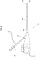
- Fig. 1 is composed of Fig. 1A showing an endoscope system 10 used in combination with a surgical treatment apparatus 20 and Fig. 1B showing the surgical treatment apparatus 20 including an ultrasound treatment tool 21.
- the endoscope system 10 comprises an endoscope 12, a light source device 14, a processor device 15, a display 16, and a user interface (UI) 17.
- the endoscope 12 images an observation target.
- the light source device 14 emits illumination light with which the observation target is irradiated.
- the processor device 15 performs system control of the endoscope system 10.
- the display 16 is a display unit that displays an observation image or the like based on an endoscope image.
- the user interface (UI) 17 is an input device that performs setting input or the like to the processor device 15 or the like, such as a mouse and a keyboard.
- the endoscope 12 is optically connected to the light source device 14 and is electrically connected to the processor device 15.
- the endoscope 12 has an insertion part 12a to be inserted into a subject, an operating part 12b provided at a proximal end portion of the insertion part 12a, a bendable part 12c provided on a distal end side of the insertion part 12a, and a distal end part 12d.
- an angle knob 12e of the operating part 12b By operating an angle knob 12e of the operating part 12b, the bendable part 12c is bent.
- the distal end part 12d is directed in a desired direction.
- a forceps port 12f is provided in the operating part 12b, in addition to the angle knob 12e.
- the forceps port 12f is an inlet into which an endoscope treatment tool such as the ultrasound treatment tool 21 is inserted.
- the endoscope treatment tool is used in a state of being inserted into the forceps port 12f.
- An observation window and an illumination window are provided in a distal end surface of the distal end part 12d, although not shown.
- An image sensor (not shown) or the like is disposed behind the observation window, and an optical fiber cable (not shown) is disposed behind the illumination window.
- Each of the signal line of the image sensor and the optical fiber cable is connected to the processor device 15 and the light source device 14.
- the processor device 15 is electrically connected to the display 16 and the user interface 17.
- the processor device 15 performs image processing or the like on an endoscope image captured by the image sensor and displays the processed image on the display 16.
- the surgical treatment apparatus 20 comprises the ultrasound treatment tool 21 that is one of endoscope treatment tools inserted into the subject through the endoscope 12 and an ultrasound drive unit 22 that supplies power.
- the ultrasound treatment tool 21 has a flexible tubular sheath 21a, an operating part 21b, and a probe 30 and is electrically connected to the ultrasound drive unit 22.
- the flexible tubular sheath 21a is a tubular sheath formed of a material having flexibility, for example, a soft resin and is inserted into a forceps channel 12g of the endoscope 12.
- the surgical treatment apparatus 20 having the ultrasound treatment tool 21 is used in, for example, sealing and incision in a case of laparoscopic surgery.
- the probe 30 is positioned at a distal end of the ultrasound treatment tool 21 and grips a biological tissue.
- the biological tissue to be gripped is a soft tissue such as a blood vessel.
- the forceps channel 12g for inserting the ultrasound treatment tool 21 is provided in the insertion part 12a having the distal end part 12d.
- the probe 30 of the ultrasound treatment tool 21 inserted into the forceps port 12f protrudes from a forceps outlet 12h of the distal end part 12d.
- One end of the forceps channel 12g is connected to a forceps outlet 23, and the other end thereof is connected to the forceps port 12f provided in the operating part 12b.
- the forceps channel 12g is also used as a path for feeding a cleaning liquid such as water from the forceps outlet 12h and a path for sucking a body fluid such as blood and contents such as body waste materials.
- the ultrasound drive unit 22 supplies power to the ultrasound treatment tool 21.
- the probe 30 has a pair of grip pieces 31 that can be opened and closed in an up-down direction, an opening and closing mechanism 32 that opens and closes the grip pieces 31, and a support member 33 that supports the grip pieces 31.
- the flexible tubular sheath 21a partially includes the support member 33.
- (A) of Fig. 3 shows a state where the grip pieces 31 are closed
- (B) of Fig. 3 shows a state where the grip pieces 31 are open.
- Each of the grip pieces 31a and 31b is formed in a semi-cylindrical shape, and the probe 30 in the closed state has a cylindrical shape or a shape that is equal to or smaller than at least a circumference of the flexible tubular sheath 21a.
- acoustic matching layers 35 are provided on inner surfaces of the pair of grip pieces 31 and surfaces facing each other. The opening and closing of the grip pieces 31 is opening and closing of the probe 30.
- a structure S such as a blood vessel is passed between the grip piece 31a and the grip piece 31b in a state where the probe 30 is open, and the probe 30 is closed. Accordingly, the inner surfaces of the pair of grip pieces 31a and 31b can be brought close to each other, and the structure S such as a blood vessel, which is a soft tissue, can be gripped with the structure S sandwiched between the pair of grip pieces 31.
- the structure S such as a blood vessel to be treated, for example, to be sealed is sandwiched between the grip pieces 31 in such a manner.
- the blood vessel and the like contain a large amount of moisture, which is a factor for delaying a temperature rise.
- an appropriate grip pressure at which the sealing effect can be obtained is 10 to 50 N.
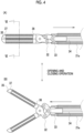
- Fig. 4 is a cross-sectional view near the probe 30, and (A) of Fig. 4 shows a cross-sectional view in a state where the probe 30 is closed and (B) of Fig. 4 shows a cross-sectional view in a state where the probe 30 is open.
- An operation wire 34 is inserted into the flexible tubular sheath 21a.
- the operation wire 34 transmits an opening and closing operation of the operating part 21b of the ultrasound treatment tool 21 by a user to the opening and closing mechanism 32.
- the opening and closing mechanism 32 is brought into a closed state as the operation wire 34 is pulled by the flexible tubular sheath 21a and is brought into an open state as the operation wire 34 is pushed into the distal end part.
- the acoustic matching layers 35, ultrasound oscillators 36, and backing members 37 are embedded in the inner surfaces of the grip piece 31a and the grip piece 31b between which the structure S is sandwiched.
- ultrasound oscillation caused by the ultrasound oscillator 36 the temperature of the structure S such as a blood vessel is raised, and the structure S is sealed.
- One surface of the ultrasound oscillator 36 is fixed to a probe housing with the backing member 37 sandwiched therebetween, and the other surface is covered with an insulating layer and/or the acoustic matching layer 35.
- a cross-sectional view taken along line VI-VI in (A) of Fig. 4 will be described with reference to Fig. 5 .
- the acoustic matching layer 35 and the ultrasound oscillator 36 are laminated in parallel inside each of the grip pieces 31a and 31b of the probe 30.
- the backing member 37 is composed of a material having stiffness, such as hard rubber, or the like and supports the ultrasound oscillator 36 from a grip piece side, which is a back side (an opposite side to the acoustic matching layer 35). It is preferable that the backing member 37 has an arc shape along the semi-cylindrical shape of each of the grip pieces 31a and 31b.
- the ultrasound oscillator 36 has a configuration where an electrode layer 38a and an electrode layer 38b formed in a plate shape thinner than a piezoelectric element 39 are laminated on both surfaces of the piezoelectric element 39 formed in a plate shape.
- the piezoelectric element 39 has a rectangular planar shape and is polarized in a thickness direction. Accordingly, a direction of ultrasound oscillation caused by the ultrasound oscillator 36 and a grip direction Y in which the probe 30 grips are parallel to each other. In addition, a direction Dk in which the ultrasound oscillator 36 oscillates is parallel to a thickness direction Dx of the piezoelectric element 39.
- the acoustic matching layer 35 is provided in order to match acoustic impedance between a human body of a patient and the ultrasound oscillator 36.
- the acoustic matching layer 35 is laminated on an outside of the ultrasound oscillator 36, in a strict sense, on a side facing the structure S gripped by the probe 30 with respect to the ultrasound oscillator 36.
- the acoustic matching layer 35 can increase transmittance of ultrasound waves.
- the acoustic matching layer 35 As a material for the acoustic matching layer 35, various organic materials of which acoustic impedance having a value close to the value of the human body, compared to the piezoelectric element 39, can be used. Specific examples thereof include an epoxy resin, silicon rubber, polyimide, and polyethylene.
- the acoustic matching layer 35 is formed of a plurality of layers, and a material and the number of layers to be composed are selected as appropriate according to the value of required acoustic impedance.
- An air gap layer 40 which is a gap capable of reflecting ultrasound waves with internal air, is formed between the electrode layer 38b on an outer surface side of the plate-shaped ultrasound oscillator 36 and the arc-shaped backing member 37.
- the air gap layer 40 has a function of reflecting the ultrasound waves emitted from a back side of the ultrasound oscillator 36 and can efficiently transmit ultrasound oscillation to the structure S such as a blood vessel.
- a material that reflects ultrasound waves may fill instead of the air gap layer 40.
- the piezoelectric element 39 having a mechanical quality coefficient Qm of 500 or more.
- the mechanical quality coefficient Qm is a coefficient representing an elasticity loss caused by oscillation and is represented by a reciprocal of a mechanical loss coefficient. In a case where the piezoelectric element 39 elastically oscillates, a loss occurs internally and is converted into heat.
- the Curie temperature of the piezoelectric element 39 is desirably equal to or more than approximately 1.5 times and preferably 2 times a target reaching temperature of a surface of the piezoelectric element during power supply.
- the Curie temperature of the piezoelectric element 39 to be used is set to 300°C or more and preferably 400°C or more. Since there is a possibility in which protein is carbonized at a temperature higher than 200°C, the target reaching temperature is preferably 200°C at its maximum.
- the probe 30 including the piezoelectric element 39 has a size that can be used in endoscopic surgery or laparoscopic surgery, and it is desirable that the thickness of the piezoelectric element 39 alone, which is a thickness that can be accommodated in the probe 30, is in a range of 0.2 mm to 1 mm, the width is in a range of 2 mm to 4 mm, and the length is in a range of 10 mm to 30 mm.
- the width and the length of the piezoelectric element 39 are allowed to be divided into two parts. For example, two parts having a width of 1 mm are arranged to have a total width of 2 mm.
- the thickness of the piezoelectric element 39 In a case where the thickness of the piezoelectric element 39 is thick, heat generated on a surface side of the piezoelectric element 39 not being in contact with a biological tissue is unlikely to be transmitted compared to a surface side in contact with the biological tissue, and a temperature difference between both surfaces tends to be large. On the other hand, in a case where the thickness of the piezoelectric element 39 is thin, the amount of heat generated by the entire piezoelectric element is reduced. In addition, the resonance frequency and the anti-resonance frequency of the piezoelectric element 39 in a state of being accommodated in the probe 30 depend on the thickness of the piezoelectric element, and the frequency tends to be higher as the piezoelectric element 39 is thinner.
- a member that holds one surface of the piezoelectric element 39 is held by the probe housing via the backing member 37 having a low thermal conductivity, and a surface on the side in contact with a biological tissue is covered with the acoustic matching layer 35 consisting of a member having a high thermal conductivity or a surface protective layer having a high thermal conductivity.
- the acoustic matching layer 35 consisting of a member having a high thermal conductivity or a surface protective layer having a high thermal conductivity.
- a difference in thermal expansion factor between the piezoelectric element 39 and the acoustic matching layer 35 causes internal stress between the ultrasound oscillator 36 and the acoustic matching layer 35 during a temperature rise, and thus is a factor for a temperature-dependent fluctuation of a resonance frequency fr and an anti-resonance frequency fa of the piezoelectric element to be described later. Therefore, the acoustic matching layer 35 is selected in consideration of the thermal expansion factor of the piezoelectric element 39.
- the probe has a small temperature change in the resonance frequency and the anti-resonance frequency.
- the following two expressions (4) and (5) are satisfied with a resonance frequency frs of the treatment start temperature, a resonance frequency fre of a maximum reaching temperature, and an anti-resonance frequency fas of the treatment start temperature.
- Resonance frequency fre of maximum reaching temperature ⁇ resonance frequency frs of treatment start temperature (Resonance frequency frs of treatment start temperature - resonance frequency fre of maximum reaching temperature) ⁇ (anti-resonance frequency fas of treatment start temperature - resonance frequency frs of treatment start temperature)*2
- the electrode layers 38a and 38b are connected to the ultrasound drive unit 22 via a signal cable (not shown) constituting a power supply circuit.
- the signal cable is provided in the flexible tubular sheath 21a.
- the signal cable is wired along an inner peripheral surface or an outer peripheral surface of the flexible tubular sheath 21a.
- the electrode layers 38a and 38b are electrically connected to the ultrasound drive unit 22 via the signal cable.
- One of the electrode layers 38a and 38b is connected to the ground via the signal cable or the like, and the other is supplied with power of an alternating current voltage signal to be described later from the ultrasound drive unit 22.
- the ultrasound drive unit 22 constituting the surgical treatment apparatus 20 comprises a control mechanism 41, a signal transmitter 42, an amplifier 43, an impedance matching circuit 44, and a frequency monitor 47, and the impedance matching circuit 44 is connected to the ultrasound oscillator 36 including the piezoelectric element 39 of the probe 30 of the ultrasound treatment tool 21.
- the control mechanism 41 controls the amount of power supplied to the piezoelectric element 39, and a path connecting the signal transmitter 42, the amplifier 43, the impedance matching circuit 44, and the ultrasound oscillator 36 includes a power supply circuit for driving the piezoelectric element.
- a program related to various types of processing is stored in a program memory (not shown) of the ultrasound drive unit 22.
- the control mechanism 41 composed of a processor realizes functions of the signal transmitter 42, the amplifier 43, and the impedance matching circuit 44 by executing the program in the program memory.
- the signal transmitter 42 has a function of generating an alternating current voltage signal having any frequency and waveform and has, for example, the same configuration and function as a known function generator. It is preferable that the ultrasound drive unit 22 is provided with a current probe (not shown) and a current value monitor (not shown) composed of an oscilloscope or the like.
- the signal transmitter 42 outputs an alternating current voltage signal having a predetermined frequency.
- the predetermined frequency is a frequency at which ultrasound oscillation of the piezoelectric element 39 is maximized, that is, the resonance frequency fr.
- the signal transmitter 42 outputs an alternating current voltage signal having a driving frequency f, for example, the resonance frequency fr to the amplifier 43.
- the amplifier 43 amplifies the alternating current voltage signal output from the signal transmitter 42 to a voltage level at which the ultrasound oscillator 36 can be driven.
- the impedance matching circuit 44 is connected in series with the amplifier 43 and can match input impedance of the alternating current voltage signal output from the amplifier 43 with impedance of the ultrasound oscillator 36.
- the current probe measures a current value input from the impedance matching circuit 44 to the ultrasound oscillator 36 and inputs the current value to the control mechanism 41. In addition, the current value is displayed on the current value monitor.
- the control mechanism 41 controls the signal transmitter 42 such that the current value measured by the current probe drives the ultrasound oscillator 36.
- the control mechanism 41 controls the signal transmitter 42 such that an alternating current voltage signal for driving the ultrasound oscillator 36 is continuously supplied.
- the term "continuously supplied” herein means that the alternating current voltage signal is continuously output from the signal transmitter 42 without interruption at least during the driving of the ultrasound oscillator 36.
- the present invention is to make power consumption contributing to self-heating in the piezoelectric element 39 larger than power consumption contributing to ultrasound oscillation and is realized by impedance adjustment. That is, the surgical treatment apparatus 20 having the impedance matching circuit 44 that takes self-heating of the piezoelectric element 39 into consideration is used.
- the impedance matching circuit 44 that adjusts impedance is realized based on results obtained in impedance measurement that is an example shown in Figs. 7 to 10 .
- a temperature rise experiment in which C-213 (manufactured by Fuji Ceramics Co., Ltd.) having a thickness of 0.5 mm, a length of 3 mm, and a width of 18 mm is adopted as the piezoelectric element 39 and impedance characteristics are measured and adjusted at 25°C, will be described.
- a frequency at which a resistance component is maximized is the anti-resonance frequency fa
- a frequency at which admittance is maximized is the resonance frequency fr.
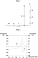
- Fig. 7 is an equivalent circuit of the piezoelectric element 39, and a value of each element can be estimated by measuring impedance characteristics and admittance characteristics.
- this equivalent circuit it is possible to estimate power consumption contributing to generation of ultrasound oscillation of the piezoelectric element 39 from an electric resistance R0 and power consumption contributing to self-heating from an electric resistance Rs.
- Fig. 8 is an impedance characteristic that is a ratio of a voltage to a current in the piezoelectric element 39 according to the present embodiment before impedance adjustment.
- a curve 50 indicates a resistance component of the impedance characteristic, and a curve 51 indicates a reactance component of the impedance characteristic.
- a curve 52 in Fig. 9 is a reciprocal of an admittance characteristic, that is, the impedance characteristic in a case of being measured under the same conditions as in Fig. 8 and indicates a ratio of a current to a voltage.
- the resonance frequency fr in a piezoelectric element 38 is 4.2 MHz
- the anti-resonance frequency fa is 4.5 MHz.
- the driving frequency f is set to a frequency at which ultrasound oscillation in the ultrasound oscillator 36 is maximized, that is, the resonance frequency fr.
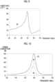
- Fig. 10 is a breakdown of power consumption in a case where an alternating current voltage of 10 V is applied to the equivalent circuit of Fig. 7 .
- a power consumption curve 53 indicates total power consumption corresponding to a frequency
- a power consumption curve 54 indicates power consumption contributing to generation of ultrasound oscillation
- a power consumption curve 55 indicates power consumption contributing to self-heating.
- the piezoelectric element 39 is driven at a frequency at which ultrasound oscillation is maximized, that is, the resonance frequency fr, and the power consumption contributing to ultrasound oscillation is larger than the power consumption contributing to self-heating.
- the resonance frequency fr is set slightly closer to the anti-resonance frequency fa, and a proportion of the power consumption contributing to generation of ultrasound oscillation in the total power consumption increases in some cases.
- the power consumption contributing to self-heating of the probe 30 is a difference between the total power consumption and the power consumption contributing to generation of ultrasound oscillation.
- the proportion of power consumption contributing to self-heating in the total power consumption of the piezoelectric element 39 is increased, and based on the above measurement result, the impedance matching circuit 44 is constructed in which a reactance component of impedance is set to 0 ⁇ at the driving frequency f at which power consumption contributing to generation of ultrasound oscillation and power consumption contributing to self-heating are at a desired ratio.
- the driving frequency f is determined in a range where power consumption contributing to generation of ultrasound oscillation at the driving frequency f is at least 25% or more of power consumption contributing to generation of ultrasound oscillation at the resonance frequency fr.
- a circuit in which impedance adjustment is performed in consideration of self-heating is constructed based on the above measurement result.
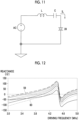
- an inductor L, a capacitor C, a power source AC, and the piezoelectric element 39 are included. Impedance is adjusted with respect to the equivalent circuit, and a time required for raising the temperature of a biological tissue is shortened.
- the temperature rising time is long, heat transmitted to a treatment portion is diffused in the biological tissue, the temperature of a living body portion in the vicinity of treatment rises, and the living body portion is damaged by heat. Therefore, it is advantageous that the temperature rising time is shorter in order to minimize heat diffusion in the biological tissue.
- a frequency at which an absolute value of admittance, which is a ratio of a current to a voltage in an alternating current circuit, is maximized is substituted for the resonance frequency fr, and a frequency at which the absolute value of the admittance is minimized is substituted for the anti-resonance frequency fa.
- the impedance matching circuit 44 in which the reactance component of the impedance characteristic of the probe 30 at the resonance frequency fr is set to 0 ⁇ , optimizes ultrasound oscillation efficiency of the probe at the resonance frequency fr.
- the present inventors have found that a probe performance required in a case of treatment such as sealing and incision is important in terms of thermal energy as well as ultrasound energy. Therefore, it is desired that the probe 30 is driven under a condition in consideration of an output of thermal energy, that is, the self-heating of the piezoelectric element 39, in addition to the ultrasound energy, and a driving method for this purpose is found.
- Fig. 12 shows a change in a reactance accompanied by the impedance adjustment realized in Fig. 11 .
- the capacitor C is adjusted in a range of 0.4 nF to 1.2 nF, and in any case, the inductor L is 4 ⁇ H.
- a curve 59 indicates a reactance corresponding to the driving frequency f at which the capacitor C is 1.2 nF
- a curve 60 indicates a reactance corresponding to the driving frequency f at which the capacitor C is 0.4 nF.
- the optimal driving frequency f is low with an increase in the reactance component, and the total power consumption tends to increase, but ultrasound oscillation reduces.
- the optimal driving frequency f is a frequency at which a reactance component on a low range side of a frequency at which the reactance component is a maximum value is 0 ⁇ .
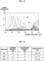
- Fig. 13 shows a breakdown of probe power consumption accompanied by impedance adjustment.
- Power consumption contributing to self-heating of the probe corresponds to a difference between total power consumption and power consumption contributing to generation of ultrasound oscillation.
- a power consumption curve group 62 shown by a dotted line is total power consumption in a value of each capacitor C
- a power consumption curve group 63 shown by a solid line is power consumption related to ultrasound oscillation in a value of each capacitor C. Therefore, it is desirable to select the optimal driving frequency f in consideration of a ratio of self-heating to ultrasound oscillation after securing the total power consumption of the probe and to perform impedance adjustment. Accordingly, the temperature rising time of the piezoelectric element 39 is shortened. As the value of the optimal driving frequency f is lower, the total power consumption of the probe 30 having the piezoelectric element 39 increases, and power consumption contributing to generation of ultrasound oscillation reduces.
- the temperature dependence of the resonance frequency fr and the anti-resonance frequency fa of the probe 30 increases due to an ancillary environment of the piezoelectric element, that is, interference with the backing member 37, the acoustic matching layer 35, and the like.
- the driving frequency f is set in consideration of a target reaching temperature zone. Specifically, in a case where the resonance frequency fr of the probe 30 fluctuates in a range from the treatment start temperature to the target reaching temperature, the driving frequency f may be the driving frequency f satisfying an allowable range of the resonance frequency fr and the driving frequency f in each temperature zone between the treatment start temperature and the target reaching temperature of the probe 30.
- the present invention drives the piezoelectric element 39 at a frequency lower than the resonance frequency fr of the piezoelectric element 39 in a state of being accommodated in the probe 30 with a state where ultrasound oscillation is also considerably generated as a condition, while mainly optimizing a driving condition for actively promoting self-heating of the piezoelectric element 39.
- An impedance matching circuit for this purpose is added to the surgical treatment apparatus 20.
- the actual driving frequency f does not need to be exact.
- the resonance frequency fr is 4.2 MHz
- the anti-resonance frequency fa is 4.5 MHz
- a range of the driving frequency f is 3.3 MHz or more and less than 4.2 MHz.
- the resonance frequency fr is 4.1 MHz
- the anti-resonance frequency fa is 4.4 MHz
- the range of the driving frequency f is 3.2 MHz or more and less than 4.1 MHz.
- the resonance frequency fr is 3.9 MHz
- the anti-resonance frequency fa is 4.3 MHz
- the range of the driving frequency f is 2.7 MHz or more and less than 3.9 MHz.
- the range of the driving frequency f is 3.3 MHz or more and less than 3.9 MHz. A method of calculating the range of the driving frequency at each temperature will be described later.
- Fig. 15 shows temperature dependence of a probe impedance characteristic in a range of the treatment start temperature of 30°C and the maximum reaching temperature of 200°C.
- a 30°C curve 65 indicates a resistance in a case of 30°C
- a 30°C curve 66 indicates a reactance in a case of 30°C.
- a 100°C curve 67 indicates a resistance in a case of 100°C
- a 100°C curve 68 indicates a reactance in a case of 100°C.
- a 200°C curve 69 indicates a resistance in a case of 200°C
- a 200°C curve 70 indicates a reactance in a case of 200°C.
- the resonance frequency fr and the anti-resonance frequency fa in this case are as shown in Fig. 14 .
- Each of the 30°C curve 66, the 100°C curve 68, and a 100°C curve 70 has a frequency at which the reactance component is 0 ⁇ , and the range of the optimal driving frequency f at each temperature is lower than a value of the frequency.
- the driving frequency f at which total power consumption is maximized is different for each temperature zone.
- the total power consumption is maximized near 3.8 MHz around 30°C.
- the total power consumption is maximized near 3.7 MHz around 100°C.
- the total power consumption is maximized near 3.6 MHz around 200°C.
- the probe 30 has a lower value of the optimal driving frequency as the reaching temperature of the piezoelectric element 39 is higher.
- the amount of heat generated by the piezoelectric element 39 is controlled by adjusting a voltage or a current in a power supply circuit.
- the driving frequency f during a temperature rise is fixed, but in a case where the temperature dependence of the resonance frequency fr of the probe 30 is large, a function of sequentially changing to the driving frequency f optimal for a probe temperature based on probe temperature data obtained by a temperature determination device (not shown) of the probe 30 may be provided.
- a biological tissue is gripped by the probe 30 including the piezoelectric element 39, heat from self-heating of the piezoelectric element 39 is conducted to the biological tissue with the start of supply of predetermined power, and ultrasound oscillation generated in association with the self-heating is added, so that sealing of the biological tissue is effectively performed by a synergistic effect of heat, oscillation, and a grip pressure.
- the driving frequency f of the probe 30 is a frequency lower than the resonance frequency fr of the probe 30 and there is the impedance matching circuit 44 in which a reactance component of impedance of the probe 30 is 0 ⁇ at the driving frequency f.
- the driving frequency f of the probe is provided in a range for efficiently raising the temperature, the range being determined by the resonance frequency fr of the probe and the anti-resonance frequency fa of the probe.
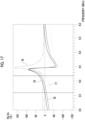
- Fig. 17 is results of impedance measurement and impedance adjustment in a case where the piezoelectric element 39 accommodated in the probe 30 is a product having a thickness of 0.5 mm, which is C-213.
- the driving frequency f is shifted to the low range side.
- a curve 76 is a resistance curve of an impedance characteristic.
- a curve 77 is a reactance curve of the impedance characteristic, and the driving frequency f is 4.2 MHz.
- An adjustment curve 78 is a case where the driving frequency f is adjusted to 3.9 MHz
- an adjustment curve 79 is a case where the driving frequency f is adjusted to 3.6 MHz.
- a frequency at which the curve 77 has a frequency of 0 ⁇ on the low range side is the resonance frequency fr, and a frequency on a high range side is the anti-resonance frequency fa.
- a frequency at which reactance components of the adjustment curve 78 and the adjustment curve 79 are 0 ⁇ is the driving frequency f on the low range side and is approximately 4.5 MHz, that is, the anti-resonance frequency fa on the high range side.
- the amount of heat generated by the piezoelectric element 39 in the probe 30 increases with the shift of the driving frequency f to the low range side, the amount of heat transmitted to a biological tissue, that is, a temperature rising speed of the biological tissue increases, and a treatment time until sealing is shortened.
- Probe power consumption depends on an applied voltage, and a desired temperature rising speed and a desired target reaching temperature are maintained by adjusting an alternating current voltage.
- power consumption of the probe 30 increases as the adjusted driving frequency f is closer to the low range side.
- power consumption of a power consumption curve 90 in a case where the driving frequency f is adjusted to 3.9 MHz is larger than that of a power consumption curve 91 in a case where the driving frequency f is adjusted to 4.2 MHz, and power consumption of a power consumption curve 89 in a case where the driving frequency f is adjusted to 3.6 MHz is even larger. That is, with the adjustment, total power consumption of the probe 30 increases as the optimal driving frequency f takes a lower value.
- the range of the driving frequency f in impedance characteristic of the probe 30 alone it is preferable that a relationship between the driving frequency f, the resonance frequency fr, and the anti-resonance frequency fa of the probe satisfies the following expression (6).
- the driving frequency f is a value lower than the resonance frequency fr. In a case where the driving frequency f is set to a frequency lower than the above range, ultrasound oscillation of the probe 30 is hardly obtained.
- a value used in calculating the range of the driving frequency f is the value shown in Fig. 14 . 4 fr ⁇ 3 fa ⁇ f ⁇ fr
- both the pair of grip pieces 31a and 31b constituting the probe 30 comprise the ultrasound oscillator 36.
- the ultrasound oscillator 36 may be provided at only one of the pair of grip pieces 31a and 31b. In this case, it is preferable that the ultrasound oscillator 36 is disposed parallel to the inner surface of one grip piece 31 and the inner surface of the other grip piece 31 facing the ultrasound oscillator 36 is formed of a material reflecting ultrasound oscillation caused by the ultrasound oscillator 36.
- processors include a central processing unit (CPU) that is a general-purpose processor which functions as various types of processing units by executing software (program), a graphical processing unit (GPU), a programmable logic device (PLD) that is a processor capable of changing a circuit configuration after manufacture, such as a field programmable gate array (FPGA), and a dedicated electric circuit that is a processor having a circuit configuration specifically designed to execute various types of processing.
- CPU central processing unit
- PLD programmable logic device
- FPGA field programmable gate array
- One processing unit may be composed of one of the various types of processors or may be composed of a combination of two or more processors of the same type or different types (for example, a combination of a plurality of FPGAs, a combination of a CPU and an FPGA, or a combination of a CPU and a GPU).
- one processor may constitute a plurality of processing units.
- one processor constitutes a plurality of processing units, first, there is a form in which one processor is configured by a combination of one or more CPUs and software and the processor functions as the plurality of processing units, as represented by a computer such as a client and a server.
- SoC system on chip
- a hardware structure of a storage unit is a storage device such as a hard disc drive (HDD) and a solid state drive (SSD).
- HDD hard disc drive
- SSD solid state drive
- the endoscope 12 to be combined with the ultrasound treatment tool 21 according to the embodiment of the present invention is not specified, and the endoscope 12 need only comprise the forceps channel into which the treatment tool is inserted, for example, a bronchoscope, an upper gastrointestinal endoscope, a lower gastrointestinal endoscope, or the like. It is preferable that the surgical treatment apparatus 20 having the impedance matching circuit 44 of the present embodiment is realized during manufacturing in a factory or the like.
Landscapes
- Health & Medical Sciences (AREA)
- Surgery (AREA)
- Life Sciences & Earth Sciences (AREA)
- Engineering & Computer Science (AREA)
- Heart & Thoracic Surgery (AREA)
- Nuclear Medicine, Radiotherapy & Molecular Imaging (AREA)
- Biomedical Technology (AREA)
- Medical Informatics (AREA)
- Molecular Biology (AREA)
- Animal Behavior & Ethology (AREA)
- General Health & Medical Sciences (AREA)
- Public Health (AREA)
- Veterinary Medicine (AREA)
- Mechanical Engineering (AREA)
- Dentistry (AREA)
- Surgical Instruments (AREA)
Abstract
Description
- The present invention relates to a surgical treatment apparatus.
- In a medical field, it is known that various types of treatment are performed on a subject by using an ultrasound treatment tool that generates ultrasound oscillation.
JP2013-528071A JP2015-43879A WO2017/038722A describes an ultrasonic surgical system having a control circuit that controls driving power output from an output circuit such that a temperature of a predetermined part of a cartilage is 120°C or more within 2.2 seconds in cutting for heating the predetermined part of the cartilage through ultrasound oscillation and for scraping off the cartilage. As the ultrasound oscillation, a resonance frequency of the piezoelectric element alone or a piezoelectric element unit is used. - In the ultrasound transducer described in
JP2013-528071A JP2015-43879A WO2017/038722A , the cartilage is scraped off by interaction of oscillation and heat. The temperature of the cartilage is set to a specified temperature within a range of 45°C to 220°C and preferably 120°C to 160°C. A heat generating rate of a soft tissue such as a blood vessel caused by the ultrasound oscillation is significantly lower than that of the cartilage, and it is difficult to raise the temperature of the soft tissue such as a blood vessel to the same extent as a cartilage portion. - In an existing treatment tool using ultrasound waves, some of the ultrasound waves are converted into frictional heat to raise a temperature in the vicinity of a treatment portion such as a blood vessel, and thus a time required for the temperature to rise to a desired temperature is long. Further, a rod-like transmission element for transmitting powerful ultrasound oscillation to the treatment portion is used, and thus the size of the treatment tool is large, and there are no bending properties. Therefore, it is difficult to use the treatment tool in endoscopic/laparoscopic surgery. In addition, in a case where a unit that heats and raises a temperature in the vicinity of the treatment portion, such as a blood vessel, is used in combination, there is a risk in which the time required for the temperature to rise to the desired temperature is long, and heat is widely transmitted to a biological tissue other than the treatment portion, causing damage. Therefore, it is required to efficiently cause self-heating with respect to a sealing treatment portion such as a blood vessel in addition to ultrasound oscillation in order to directly transmit heat from the self-heating to the vicinity of the treatment portion, to shorten the time required for the temperature to rise to the desired temperature, and to minimize damage to the vicinity of the treatment portion caused by the spread of heat to the biological tissue.
- An object of the present invention is to provide a surgical treatment apparatus that can directly transmit ultrasound waves and heat from self-heating to a soft tissue such as a blood vessel, shorten a time required for sealing, and minimize damage caused by spread of heat to a biological tissue in the vicinity of the soft tissue.
- According to an aspect of the present invention, there is provided a surgical treatment apparatus comprising a probe that includes a piezoelectric element, a power supply circuit for driving the piezoelectric element, a power supply wiring line to the piezoelectric element, a flexible tubular sheath, a control mechanism of an amount of power supplied to the piezoelectric element, and an impedance matching circuit, in which the probe has electrode layers for power supply on both surfaces of the piezoelectric element and an opening and closing mechanism for gripping a biological tissue, the flexible tubular sheath includes the power supply wiring line to the piezoelectric element and a part of the opening and closing mechanism of the probe, a driving frequency used in power supply to the piezoelectric element is a frequency lower than a resonance frequency in an impedance characteristic of the probe, and the impedance matching circuit sets the driving frequency used in the power supply to the piezoelectric element to a frequency lower than the resonance frequency in the impedance characteristic of a treatment start temperature of the probe and a frequency at which a reactance component of impedance at the driving frequency is 0 Ω.
- It is preferable that in a case where the driving frequency of the probe is denoted by f, the resonance frequency is denoted by fr, an anti-resonance frequency is denoted by fa, a range of the driving frequency in the impedance characteristic of the treatment start temperature of the probe alone satisfies the following expression (1).

- It is more preferable that a range of the driving frequency in the impedance characteristic of the treatment start temperature of the probe alone satisfies the following expression (2).

- It is most preferable that a range of the driving frequency in the impedance characteristic of the treatment start temperature of the probe alone satisfies the following expression (3).

- It is preferable that the piezoelectric element consists of a rectangular planar shape and is polarized in a thickness direction.
- It is preferable that one surface of the piezoelectric element is fixed to the probe with a backing member sandwiched therebetween and that the other surface of the piezoelectric element is covered with at least one of or both an acoustic matching layer and an insulating layer.
- It is preferable that the biological tissue is a soft tissue including a blood vessel.
- It is preferable that the driving frequency is a frequency lower than the resonance frequency and is a frequency at which power consumption contributing to generation of ultrasound oscillation at the driving frequency is in a range of at least 25% or more of power consumption contributing to generation of ultrasound oscillation at the resonance frequency.
- It is preferable that in the probe, the resonance frequency in an impedance characteristic of a maximum reaching temperature of the piezoelectric element is equal to or lower than the resonance frequency in the impedance characteristic of the treatment start temperature, and a difference between the resonance frequency in the impedance characteristic of the maximum reaching temperature of the piezoelectric element and the resonance frequency in the impedance characteristic of the treatment start temperature is equal to or less than two times a difference between the resonance frequency and an anti-resonance frequency in the impedance characteristic of the treatment start temperature of the piezoelectric element.
- With the present invention, ultrasound waves and heat from self-heating can be directly transmitted to a soft tissue such as a blood vessel, shorten a time required for sealing, and minimize damage caused by spread of heat to a biological tissue in the vicinity of the soft tissue.
-
-
Fig. 1A is an explanatory view for describing a configuration of an endoscope system, andFig. 1B is an explanatory view for describing a configuration of a surgical treatment apparatus. -
Fig. 2 is an explanatory view of a state where an ultrasound treatment tool is inserted into an endoscope. -
Fig. 3 is a perspective view of a grip piece of the ultrasound treatment tool in a closed state (A) and an open state (B). -
Fig. 4 is a cross-sectional view of the grip piece of the ultrasound treatment tool in the closed state (A) and the open state (B). -
Fig. 5 is a cross-sectional view taken along line VI-VI of (A) ofFig. 4 . -
Fig. 6 is a block diagram showing an outline of the surgical treatment apparatus. -
Fig. 7 is an equivalent circuit diagram of a piezoelectric element. -
Fig. 8 is an explanatory view of an impedance characteristic of the piezoelectric element of the present embodiment. -
Fig. 9 is an explanatory view of an admittance characteristic of the piezoelectric element of the present embodiment. -
Fig. 10 is an explanatory view of power consumption in a case where an alternating current voltage of 10 V is applied to the piezoelectric element. -
Fig. 11 is an impedance matching circuit diagram in which power consumption contributing to self-heating in power consumption of a probe according to the present embodiment exceeds power consumption contributing to generation of ultrasound oscillation. -
Fig. 12 is an explanatory view showing a reactance change during impedance adjustment. -
Fig. 13 is an explanatory view of a breakdown of probe power consumption during impedance adjustment. -
Fig. 14 is an explanatory view of a resonance frequency, an anti-resonance frequency, and a driving frequency range of the probe at each temperature. -
Fig. 15 is an explanatory view of temperature dependence of the impedance characteristic. -
Fig. 16 is an explanatory view of driving frequency dependence of total power consumption of the probe. -
Fig. 17 is an explanatory view before and after impedance adjustment of the probe. -
Fig. 18 is an explanatory view of a transition of the probe power consumption after impedance adjustment. -
Fig. 1 is composed ofFig. 1A showing anendoscope system 10 used in combination with asurgical treatment apparatus 20 andFig. 1B showing thesurgical treatment apparatus 20 including anultrasound treatment tool 21. As shown inFig. 1A , theendoscope system 10 comprises anendoscope 12, alight source device 14, aprocessor device 15, adisplay 16, and a user interface (UI) 17. Theendoscope 12 images an observation target. Thelight source device 14 emits illumination light with which the observation target is irradiated. Theprocessor device 15 performs system control of theendoscope system 10. Thedisplay 16 is a display unit that displays an observation image or the like based on an endoscope image. The user interface (UI) 17 is an input device that performs setting input or the like to theprocessor device 15 or the like, such as a mouse and a keyboard. - The
endoscope 12 is optically connected to thelight source device 14 and is electrically connected to theprocessor device 15. Theendoscope 12 has aninsertion part 12a to be inserted into a subject, an operatingpart 12b provided at a proximal end portion of theinsertion part 12a, abendable part 12c provided on a distal end side of theinsertion part 12a, and adistal end part 12d. By operating anangle knob 12e of the operatingpart 12b, thebendable part 12c is bent. As a result, thedistal end part 12d is directed in a desired direction. In addition, aforceps port 12f is provided in theoperating part 12b, in addition to theangle knob 12e. Theforceps port 12f is an inlet into which an endoscope treatment tool such as theultrasound treatment tool 21 is inserted. The endoscope treatment tool is used in a state of being inserted into theforceps port 12f. - An observation window and an illumination window are provided in a distal end surface of the
distal end part 12d, although not shown. An image sensor (not shown) or the like is disposed behind the observation window, and an optical fiber cable (not shown) is disposed behind the illumination window. Each of the signal line of the image sensor and the optical fiber cable is connected to theprocessor device 15 and thelight source device 14. - The
processor device 15 is electrically connected to thedisplay 16 and theuser interface 17. Theprocessor device 15 performs image processing or the like on an endoscope image captured by the image sensor and displays the processed image on thedisplay 16. - As shown in
Fig. 1B , thesurgical treatment apparatus 20 comprises theultrasound treatment tool 21 that is one of endoscope treatment tools inserted into the subject through theendoscope 12 and anultrasound drive unit 22 that supplies power. Theultrasound treatment tool 21 has a flexibletubular sheath 21a, an operatingpart 21b, and aprobe 30 and is electrically connected to theultrasound drive unit 22. The flexibletubular sheath 21a is a tubular sheath formed of a material having flexibility, for example, a soft resin and is inserted into aforceps channel 12g of theendoscope 12. Thesurgical treatment apparatus 20 having theultrasound treatment tool 21 is used in, for example, sealing and incision in a case of laparoscopic surgery. Theprobe 30 is positioned at a distal end of theultrasound treatment tool 21 and grips a biological tissue. The biological tissue to be gripped is a soft tissue such as a blood vessel. - As shown in
Fig. 2 , theforceps channel 12g for inserting theultrasound treatment tool 21 is provided in theinsertion part 12a having thedistal end part 12d. Theprobe 30 of theultrasound treatment tool 21 inserted into theforceps port 12f protrudes from aforceps outlet 12h of thedistal end part 12d. One end of theforceps channel 12g is connected to a forceps outlet 23, and the other end thereof is connected to theforceps port 12f provided in theoperating part 12b. In addition, theforceps channel 12g is also used as a path for feeding a cleaning liquid such as water from theforceps outlet 12h and a path for sucking a body fluid such as blood and contents such as body waste materials. Theultrasound drive unit 22 supplies power to theultrasound treatment tool 21. - As shown in
Fig. 3 , theprobe 30 has a pair ofgrip pieces 31 that can be opened and closed in an up-down direction, an opening andclosing mechanism 32 that opens and closes thegrip pieces 31, and asupport member 33 that supports thegrip pieces 31. In addition, the flexibletubular sheath 21a partially includes thesupport member 33. (A) ofFig. 3 shows a state where thegrip pieces 31 are closed, and (B) ofFig. 3 shows a state where thegrip pieces 31 are open. Each of thegrip pieces probe 30 in the closed state has a cylindrical shape or a shape that is equal to or smaller than at least a circumference of the flexibletubular sheath 21a. As shown in (B) ofFig. 3 , acoustic matching layers 35 are provided on inner surfaces of the pair ofgrip pieces 31 and surfaces facing each other. The opening and closing of thegrip pieces 31 is opening and closing of theprobe 30. - A structure S such as a blood vessel is passed between the
grip piece 31a and thegrip piece 31b in a state where theprobe 30 is open, and theprobe 30 is closed. Accordingly, the inner surfaces of the pair ofgrip pieces grip pieces 31. The structure S such as a blood vessel to be treated, for example, to be sealed is sandwiched between thegrip pieces 31 in such a manner. The blood vessel and the like contain a large amount of moisture, which is a factor for delaying a temperature rise. Therefore, by appropriately gripping (pressurizing) the structure S, the moisture contained in the biological tissue gripped by thegrip pieces 31 is extruded, and the remaining biological tissue is promoted to be denatured and adhered, thereby enhancing a sealing effect. In the present treatment tool, an appropriate grip pressure at which the sealing effect can be obtained is 10 to 50 N. -
Fig. 4 is a cross-sectional view near theprobe 30, and (A) ofFig. 4 shows a cross-sectional view in a state where theprobe 30 is closed and (B) ofFig. 4 shows a cross-sectional view in a state where theprobe 30 is open. Anoperation wire 34 is inserted into the flexibletubular sheath 21a. Theoperation wire 34 transmits an opening and closing operation of the operatingpart 21b of theultrasound treatment tool 21 by a user to the opening andclosing mechanism 32. In the opening and closing operation, the opening andclosing mechanism 32 is brought into a closed state as theoperation wire 34 is pulled by the flexibletubular sheath 21a and is brought into an open state as theoperation wire 34 is pushed into the distal end part. - The acoustic matching layers 35,
ultrasound oscillators 36, andbacking members 37 are embedded in the inner surfaces of thegrip piece 31a and thegrip piece 31b between which the structure S is sandwiched. By using ultrasound oscillation caused by theultrasound oscillator 36, the temperature of the structure S such as a blood vessel is raised, and the structure S is sealed. One surface of theultrasound oscillator 36 is fixed to a probe housing with the backingmember 37 sandwiched therebetween, and the other surface is covered with an insulating layer and/or theacoustic matching layer 35. A cross-sectional view taken along line VI-VI in (A) ofFig. 4 will be described with reference toFig. 5 . - As shown in
Fig. 5 , theacoustic matching layer 35 and theultrasound oscillator 36 are laminated in parallel inside each of thegrip pieces probe 30. The backingmember 37 is composed of a material having stiffness, such as hard rubber, or the like and supports theultrasound oscillator 36 from a grip piece side, which is a back side (an opposite side to the acoustic matching layer 35). It is preferable that the backingmember 37 has an arc shape along the semi-cylindrical shape of each of thegrip pieces ultrasound oscillator 36 has a configuration where anelectrode layer 38a and anelectrode layer 38b formed in a plate shape thinner than apiezoelectric element 39 are laminated on both surfaces of thepiezoelectric element 39 formed in a plate shape. Thepiezoelectric element 39 has a rectangular planar shape and is polarized in a thickness direction. Accordingly, a direction of ultrasound oscillation caused by theultrasound oscillator 36 and a grip direction Y in which theprobe 30 grips are parallel to each other. In addition, a direction Dk in which theultrasound oscillator 36 oscillates is parallel to a thickness direction Dx of thepiezoelectric element 39. - The
acoustic matching layer 35 is provided in order to match acoustic impedance between a human body of a patient and theultrasound oscillator 36. Theacoustic matching layer 35 is laminated on an outside of theultrasound oscillator 36, in a strict sense, on a side facing the structure S gripped by theprobe 30 with respect to theultrasound oscillator 36. Theacoustic matching layer 35 can increase transmittance of ultrasound waves. - As a material for the
acoustic matching layer 35, various organic materials of which acoustic impedance having a value close to the value of the human body, compared to thepiezoelectric element 39, can be used. Specific examples thereof include an epoxy resin, silicon rubber, polyimide, and polyethylene. In addition, theacoustic matching layer 35 is formed of a plurality of layers, and a material and the number of layers to be composed are selected as appropriate according to the value of required acoustic impedance. - An
air gap layer 40, which is a gap capable of reflecting ultrasound waves with internal air, is formed between theelectrode layer 38b on an outer surface side of the plate-shapedultrasound oscillator 36 and the arc-shapedbacking member 37. Theair gap layer 40 has a function of reflecting the ultrasound waves emitted from a back side of theultrasound oscillator 36 and can efficiently transmit ultrasound oscillation to the structure S such as a blood vessel. A material that reflects ultrasound waves may fill instead of theair gap layer 40. - It is preferable to use the
piezoelectric element 39 having a mechanical quality coefficient Qm of 500 or more. The mechanical quality coefficient Qm is a coefficient representing an elasticity loss caused by oscillation and is represented by a reciprocal of a mechanical loss coefficient. In a case where thepiezoelectric element 39 elastically oscillates, a loss occurs internally and is converted into heat. - In a case where a temperature rise caused by heat generated in the
piezoelectric element 39 exceeds 100°C, a possibility of depolarization of thepiezoelectric element 39 is also considered. The Curie temperature of thepiezoelectric element 39 is desirably equal to or more than approximately 1.5 times and preferably 2 times a target reaching temperature of a surface of the piezoelectric element during power supply. For example, in a case where the target reaching temperature of the surface of the piezoelectric element is set to 200°C, the Curie temperature of thepiezoelectric element 39 to be used is set to 300°C or more and preferably 400°C or more. Since there is a possibility in which protein is carbonized at a temperature higher than 200°C, the target reaching temperature is preferably 200°C at its maximum. - The
probe 30 including thepiezoelectric element 39 has a size that can be used in endoscopic surgery or laparoscopic surgery, and it is desirable that the thickness of thepiezoelectric element 39 alone, which is a thickness that can be accommodated in theprobe 30, is in a range of 0.2 mm to 1 mm, the width is in a range of 2 mm to 4 mm, and the length is in a range of 10 mm to 30 mm. The width and the length of thepiezoelectric element 39 are allowed to be divided into two parts. For example, two parts having a width of 1 mm are arranged to have a total width of 2 mm. In a case where the thickness of thepiezoelectric element 39 is thick, heat generated on a surface side of thepiezoelectric element 39 not being in contact with a biological tissue is unlikely to be transmitted compared to a surface side in contact with the biological tissue, and a temperature difference between both surfaces tends to be large. On the other hand, in a case where the thickness of thepiezoelectric element 39 is thin, the amount of heat generated by the entire piezoelectric element is reduced. In addition, the resonance frequency and the anti-resonance frequency of thepiezoelectric element 39 in a state of being accommodated in theprobe 30 depend on the thickness of the piezoelectric element, and the frequency tends to be higher as thepiezoelectric element 39 is thinner. - Further, in the
piezoelectric element 39, a member that holds one surface of thepiezoelectric element 39 is held by the probe housing via the backingmember 37 having a low thermal conductivity, and a surface on the side in contact with a biological tissue is covered with theacoustic matching layer 35 consisting of a member having a high thermal conductivity or a surface protective layer having a high thermal conductivity. Herein, it is also effective to provide the air gap layer in a part between theultrasound oscillator 36 and the backingmember 37 to more effectively reduce heat transfer properties. - In addition, a difference in thermal expansion factor between the
piezoelectric element 39 and theacoustic matching layer 35 causes internal stress between theultrasound oscillator 36 and theacoustic matching layer 35 during a temperature rise, and thus is a factor for a temperature-dependent fluctuation of a resonance frequency fr and an anti-resonance frequency fa of the piezoelectric element to be described later. Therefore, theacoustic matching layer 35 is selected in consideration of the thermal expansion factor of thepiezoelectric element 39. - It is preferable that, even in a case where a temperature reached by the piezoelectric element is high, the probe has a small temperature change in the resonance frequency and the anti-resonance frequency. Specifically, as a condition for selecting the thermal expansion factor of the
acoustic matching layer 35, it is preferable that the following two expressions (4) and (5) are satisfied with a resonance frequency frs of the treatment start temperature, a resonance frequency fre of a maximum reaching temperature, and an anti-resonance frequency fas of the treatment start temperature.Resonance frequency fre of maximum reaching temperature ≤ resonance frequency frs of treatment start temperature (Resonance frequency frs of treatment start temperature - resonance frequency fre of maximum reaching temperature) ≤ (anti-resonance frequency fas of treatment start temperature - resonance frequency frs of treatment start temperature)*2 - The electrode layers 38a and 38b are connected to the
ultrasound drive unit 22 via a signal cable (not shown) constituting a power supply circuit. The signal cable is provided in the flexibletubular sheath 21a. For example, the signal cable is wired along an inner peripheral surface or an outer peripheral surface of the flexibletubular sheath 21a. In a case where theultrasound treatment tool 21 is connected to theultrasound drive unit 22, the electrode layers 38a and 38b are electrically connected to theultrasound drive unit 22 via the signal cable. One of the electrode layers 38a and 38b is connected to the ground via the signal cable or the like, and the other is supplied with power of an alternating current voltage signal to be described later from theultrasound drive unit 22. - As shown in
Fig. 6 , theultrasound drive unit 22 constituting thesurgical treatment apparatus 20 comprises acontrol mechanism 41, asignal transmitter 42, anamplifier 43, animpedance matching circuit 44, and afrequency monitor 47, and theimpedance matching circuit 44 is connected to theultrasound oscillator 36 including thepiezoelectric element 39 of theprobe 30 of theultrasound treatment tool 21. Thecontrol mechanism 41 controls the amount of power supplied to thepiezoelectric element 39, and a path connecting thesignal transmitter 42, theamplifier 43, theimpedance matching circuit 44, and theultrasound oscillator 36 includes a power supply circuit for driving the piezoelectric element. - A program related to various types of processing is stored in a program memory (not shown) of the
ultrasound drive unit 22. Thecontrol mechanism 41 composed of a processor realizes functions of thesignal transmitter 42, theamplifier 43, and theimpedance matching circuit 44 by executing the program in the program memory. - A frequency actually used in a case of driving the
ultrasound oscillator 36 is displayed on thefrequency monitor 47. Thesignal transmitter 42 has a function of generating an alternating current voltage signal having any frequency and waveform and has, for example, the same configuration and function as a known function generator. It is preferable that theultrasound drive unit 22 is provided with a current probe (not shown) and a current value monitor (not shown) composed of an oscilloscope or the like. - The
signal transmitter 42 outputs an alternating current voltage signal having a predetermined frequency. The predetermined frequency is a frequency at which ultrasound oscillation of thepiezoelectric element 39 is maximized, that is, the resonance frequency fr. Thepiezoelectric element 39 has a resonance frequency according to a thickness dimension. Specifically, in a case where the thickness dimension is denoted by D1 (m), a resonance frequency according to the thickness dimension D1 is denoted by fr (MHz), and a piezoelectric sound speed (the speed of a sound wave transmitted in the piezoelectric element 39) is denoted by v (m/sec), a relationship of D1 = v/2fr is established. - The
signal transmitter 42 outputs an alternating current voltage signal having a driving frequency f, for example, the resonance frequency fr to theamplifier 43. Theamplifier 43 amplifies the alternating current voltage signal output from thesignal transmitter 42 to a voltage level at which theultrasound oscillator 36 can be driven. Theimpedance matching circuit 44 is connected in series with theamplifier 43 and can match input impedance of the alternating current voltage signal output from theamplifier 43 with impedance of theultrasound oscillator 36. - The current probe measures a current value input from the
impedance matching circuit 44 to theultrasound oscillator 36 and inputs the current value to thecontrol mechanism 41. In addition, the current value is displayed on the current value monitor. Thecontrol mechanism 41 controls thesignal transmitter 42 such that the current value measured by the current probe drives theultrasound oscillator 36. Thecontrol mechanism 41 controls thesignal transmitter 42 such that an alternating current voltage signal for driving theultrasound oscillator 36 is continuously supplied. The term "continuously supplied" herein means that the alternating current voltage signal is continuously output from thesignal transmitter 42 without interruption at least during the driving of theultrasound oscillator 36. By driving theultrasound oscillator 36, treatment by theultrasound treatment tool 21 can be performed. - The present invention is to make power consumption contributing to self-heating in the
piezoelectric element 39 larger than power consumption contributing to ultrasound oscillation and is realized by impedance adjustment. That is, thesurgical treatment apparatus 20 having theimpedance matching circuit 44 that takes self-heating of thepiezoelectric element 39 into consideration is used. - The
impedance matching circuit 44 that adjusts impedance is realized based on results obtained in impedance measurement that is an example shown inFigs. 7 to 10 . As the example, a temperature rise experiment, in which C-213 (manufactured by Fuji Ceramics Co., Ltd.) having a thickness of 0.5 mm, a length of 3 mm, and a width of 18 mm is adopted as thepiezoelectric element 39 and impedance characteristics are measured and adjusted at 25°C, will be described. - Regarding the resonance frequency fr and the anti-resonance frequency fa in the piezoelectric element 39 (the
probe 30 having the piezoelectric element 39), a frequency at which a resistance component is maximized (a reactance component is zero) is the anti-resonance frequency fa, and a frequency at which admittance is maximized is the resonance frequency fr. -
Fig. 7 is an equivalent circuit of thepiezoelectric element 39, and a value of each element can be estimated by measuring impedance characteristics and admittance characteristics. By using this equivalent circuit, it is possible to estimate power consumption contributing to generation of ultrasound oscillation of thepiezoelectric element 39 from an electric resistance R0 and power consumption contributing to self-heating from an electric resistance Rs. -
Fig. 8 is an impedance characteristic that is a ratio of a voltage to a current in thepiezoelectric element 39 according to the present embodiment before impedance adjustment. Acurve 50 indicates a resistance component of the impedance characteristic, and acurve 51 indicates a reactance component of the impedance characteristic. - A
curve 52 inFig. 9 is a reciprocal of an admittance characteristic, that is, the impedance characteristic in a case of being measured under the same conditions as inFig. 8 and indicates a ratio of a current to a voltage. From the impedance characteristic and a reactance characteristic ofFig. 8 andFig. 9 , before impedance adjustment, the resonance frequency fr in a piezoelectric element 38 is 4.2 MHz, and the anti-resonance frequency fa is 4.5 MHz. In general, the driving frequency f is set to a frequency at which ultrasound oscillation in theultrasound oscillator 36 is maximized, that is, the resonance frequency fr. -
Fig. 10 is a breakdown of power consumption in a case where an alternating current voltage of 10 V is applied to the equivalent circuit ofFig. 7 . Apower consumption curve 53 indicates total power consumption corresponding to a frequency, apower consumption curve 54 indicates power consumption contributing to generation of ultrasound oscillation, and apower consumption curve 55 indicates power consumption contributing to self-heating. Thepiezoelectric element 39 is driven at a frequency at which ultrasound oscillation is maximized, that is, the resonance frequency fr, and the power consumption contributing to ultrasound oscillation is larger than the power consumption contributing to self-heating. In addition, in order to further reduce self-heating, the resonance frequency fr is set slightly closer to the anti-resonance frequency fa, and a proportion of the power consumption contributing to generation of ultrasound oscillation in the total power consumption increases in some cases. The power consumption contributing to self-heating of theprobe 30 is a difference between the total power consumption and the power consumption contributing to generation of ultrasound oscillation. - On the other hand, in the present embodiment, the proportion of power consumption contributing to self-heating in the total power consumption of the
piezoelectric element 39 is increased, and based on the above measurement result, theimpedance matching circuit 44 is constructed in which a reactance component of impedance is set to 0 Ω at the driving frequency f at which power consumption contributing to generation of ultrasound oscillation and power consumption contributing to self-heating are at a desired ratio. In a case where the driving frequency f is excessively low, ultrasound oscillation is hardly generated. Therefore, the driving frequency f is determined in a range where power consumption contributing to generation of ultrasound oscillation at the driving frequency f is at least 25% or more of power consumption contributing to generation of ultrasound oscillation at the resonance frequency fr. - As shown in
Fig. 11 , a circuit in which impedance adjustment is performed in consideration of self-heating is constructed based on the above measurement result. Specifically, an inductor L, a capacitor C, a power source AC, and thepiezoelectric element 39 are included. Impedance is adjusted with respect to the equivalent circuit, and a time required for raising the temperature of a biological tissue is shortened. In a case where the temperature rising time is long, heat transmitted to a treatment portion is diffused in the biological tissue, the temperature of a living body portion in the vicinity of treatment rises, and the living body portion is damaged by heat. Therefore, it is advantageous that the temperature rising time is shorter in order to minimize heat diffusion in the biological tissue. - In electrical characteristics of the
probe 30 in a state of gripping an ancillary structure of the probe housing, such as theacoustic matching layer 35 adjusted for impedance and the structure S such as a blood vessel, a frequency at which an absolute value of admittance, which is a ratio of a current to a voltage in an alternating current circuit, is maximized is substituted for the resonance frequency fr, and a frequency at which the absolute value of the admittance is minimized is substituted for the anti-resonance frequency fa. - In general, the
impedance matching circuit 44, in which the reactance component of the impedance characteristic of theprobe 30 at the resonance frequency fr is set to 0 Ω, optimizes ultrasound oscillation efficiency of the probe at the resonance frequency fr. On the other hand, the present inventors have found that a probe performance required in a case of treatment such as sealing and incision is important in terms of thermal energy as well as ultrasound energy. Therefore, it is desired that theprobe 30 is driven under a condition in consideration of an output of thermal energy, that is, the self-heating of thepiezoelectric element 39, in addition to the ultrasound energy, and a driving method for this purpose is found. -
Fig. 12 shows a change in a reactance accompanied by the impedance adjustment realized inFig. 11 . The capacitor C is adjusted in a range of 0.4 nF to 1.2 nF, and in any case, the inductor L is 4 µH. Acurve 59 indicates a reactance corresponding to the driving frequency f at which the capacitor C is 1.2 nF, and acurve 60 indicates a reactance corresponding to the driving frequency f at which the capacitor C is 0.4 nF. The optimal driving frequency f is low with an increase in the reactance component, and the total power consumption tends to increase, but ultrasound oscillation reduces. The optimal driving frequency f is a frequency at which a reactance component on a low range side of a frequency at which the reactance component is a maximum value is 0 Ω. -
Fig. 13 shows a breakdown of probe power consumption accompanied by impedance adjustment. Power consumption contributing to self-heating of the probe corresponds to a difference between total power consumption and power consumption contributing to generation of ultrasound oscillation. A powerconsumption curve group 62 shown by a dotted line is total power consumption in a value of each capacitor C, and a powerconsumption curve group 63 shown by a solid line is power consumption related to ultrasound oscillation in a value of each capacitor C. Therefore, it is desirable to select the optimal driving frequency f in consideration of a ratio of self-heating to ultrasound oscillation after securing the total power consumption of the probe and to perform impedance adjustment. Accordingly, the temperature rising time of thepiezoelectric element 39 is shortened. As the value of the optimal driving frequency f is lower, the total power consumption of theprobe 30 having thepiezoelectric element 39 increases, and power consumption contributing to generation of ultrasound oscillation reduces. - The temperature dependence of the resonance frequency fr and the anti-resonance frequency fa of the
probe 30 increases due to an ancillary environment of the piezoelectric element, that is, interference with the backingmember 37, theacoustic matching layer 35, and the like. In this case, the driving frequency f is set in consideration of a target reaching temperature zone. Specifically, in a case where the resonance frequency fr of theprobe 30 fluctuates in a range from the treatment start temperature to the target reaching temperature, the driving frequency f may be the driving frequency f satisfying an allowable range of the resonance frequency fr and the driving frequency f in each temperature zone between the treatment start temperature and the target reaching temperature of theprobe 30. - The present invention drives the
piezoelectric element 39 at a frequency lower than the resonance frequency fr of thepiezoelectric element 39 in a state of being accommodated in theprobe 30 with a state where ultrasound oscillation is also considerably generated as a condition, while mainly optimizing a driving condition for actively promoting self-heating of thepiezoelectric element 39. An impedance matching circuit for this purpose is added to thesurgical treatment apparatus 20. The actual driving frequency f does not need to be exact. - As shown in
Fig. 14 , at 30°C, the resonance frequency fr is 4.2 MHz, the anti-resonance frequency fa is 4.5 MHz, and a range of the driving frequency f is 3.3 MHz or more and less than 4.2 MHz. At 100°C, the resonance frequency fr is 4.1 MHz, the anti-resonance frequency fa is 4.4 MHz, and the range of the driving frequency f is 3.2 MHz or more and less than 4.1 MHz. At 200°C, the resonance frequency fr is 3.9 MHz, the anti-resonance frequency fa is 4.3 MHz, and the range of the driving frequency f is 2.7 MHz or more and less than 3.9 MHz. In a case where the common driving frequency f is selected in a range including each temperature zone of 30°C, 100°C, and 200°C, the range of the driving frequency f is 3.3 MHz or more and less than 3.9 MHz. A method of calculating the range of the driving frequency at each temperature will be described later. -
Fig. 15 shows temperature dependence of a probe impedance characteristic in a range of the treatment start temperature of 30°C and the maximum reaching temperature of 200°C. A 30°C curve 65 indicates a resistance in a case of 30°C, and a 30°C curve 66 indicates a reactance in a case of 30°C. A 100°C curve 67 indicates a resistance in a case of 100°C, and a 100°C curve 68 indicates a reactance in a case of 100°C. A 200°C curve 69 indicates a resistance in a case of 200°C, and a 200°C curve 70 indicates a reactance in a case of 200°C. In addition, the resonance frequency fr and the anti-resonance frequency fa in this case are as shown inFig. 14 . Each of the 30°C curve 66, the 100°C curve 68, and a 100°C curve 70 has a frequency at which the reactance component is 0 Ω, and the range of the optimal driving frequency f at each temperature is lower than a value of the frequency. - As shown in
Fig. 16 , the driving frequency f at which total power consumption is maximized is different for each temperature zone. As shown in a 30°Cpower consumption curve 72, the total power consumption is maximized near 3.8 MHz around 30°C. As shown in a 100°Cpower consumption curve 73, the total power consumption is maximized near 3.7 MHz around 100°C. In addition, as shown in a 200°Cpower consumption curve 74, the total power consumption is maximized near 3.6 MHz around 200°C. Theprobe 30 has a lower value of the optimal driving frequency as the reaching temperature of thepiezoelectric element 39 is higher. - The amount of heat generated by the
piezoelectric element 39 is controlled by adjusting a voltage or a current in a power supply circuit. In addition, in general, the driving frequency f during a temperature rise is fixed, but in a case where the temperature dependence of the resonance frequency fr of theprobe 30 is large, a function of sequentially changing to the driving frequency f optimal for a probe temperature based on probe temperature data obtained by a temperature determination device (not shown) of theprobe 30 may be provided. - In the present invention, a biological tissue is gripped by the
probe 30 including thepiezoelectric element 39, heat from self-heating of thepiezoelectric element 39 is conducted to the biological tissue with the start of supply of predetermined power, and ultrasound oscillation generated in association with the self-heating is added, so that sealing of the biological tissue is effectively performed by a synergistic effect of heat, oscillation, and a grip pressure. - The driving frequency f of the
probe 30 is a frequency lower than the resonance frequency fr of theprobe 30 and there is theimpedance matching circuit 44 in which a reactance component of impedance of theprobe 30 is 0 Ω at the driving frequency f. The driving frequency f of the probe is provided in a range for efficiently raising the temperature, the range being determined by the resonance frequency fr of the probe and the anti-resonance frequency fa of the probe. -
Fig. 17 is results of impedance measurement and impedance adjustment in a case where thepiezoelectric element 39 accommodated in theprobe 30 is a product having a thickness of 0.5 mm, which is C-213. In the impedance adjustment, the driving frequency f is shifted to the low range side. Acurve 76 is a resistance curve of an impedance characteristic. Acurve 77 is a reactance curve of the impedance characteristic, and the driving frequency f is 4.2 MHz. Anadjustment curve 78 is a case where the driving frequency f is adjusted to 3.9 MHz, and anadjustment curve 79 is a case where the driving frequency f is adjusted to 3.6 MHz. A frequency at which thecurve 77 has a frequency of 0 Ω on the low range side is the resonance frequency fr, and a frequency on a high range side is the anti-resonance frequency fa. A frequency at which reactance components of theadjustment curve 78 and theadjustment curve 79 are 0 Ω is the driving frequency f on the low range side and is approximately 4.5 MHz, that is, the anti-resonance frequency fa on the high range side. - The amount of heat generated by the
piezoelectric element 39 in theprobe 30 increases with the shift of the driving frequency f to the low range side, the amount of heat transmitted to a biological tissue, that is, a temperature rising speed of the biological tissue increases, and a treatment time until sealing is shortened. Probe power consumption depends on an applied voltage, and a desired temperature rising speed and a desired target reaching temperature are maintained by adjusting an alternating current voltage. - As shown in
Fig. 18 , in the present measurement frequency range, power consumption of theprobe 30 increases as the adjusted driving frequency f is closer to the low range side. For probe power consumption in a case where a voltage of 10 V is applied, power consumption of apower consumption curve 90 in a case where the driving frequency f is adjusted to 3.9 MHz is larger than that of apower consumption curve 91 in a case where the driving frequency f is adjusted to 4.2 MHz, and power consumption of apower consumption curve 89 in a case where the driving frequency f is adjusted to 3.6 MHz is even larger. That is, with the adjustment, total power consumption of theprobe 30 increases as the optimal driving frequency f takes a lower value. - As described above, regarding the range of the driving frequency f in impedance characteristic of the
probe 30 alone, it is preferable that a relationship between the driving frequency f, the resonance frequency fr, and the anti-resonance frequency fa of the probe satisfies the following expression (6). The driving frequency f is a value lower than the resonance frequency fr. In a case where the driving frequency f is set to a frequency lower than the above range, ultrasound oscillation of theprobe 30 is hardly obtained. A value used in calculating the range of the driving frequency f is the value shown inFig. 14 .
- As a range of the driving frequency f of the
probe 30 that is more desirable than that from expression (6), it is preferable to satisfy the following expression (7).
- As the most desirable driving frequency f of the
probe 30, the following expression (8) centered in the range of expression (7) is preferably satisfied.
- In the present embodiment, both the pair of
grip pieces probe 30 comprise theultrasound oscillator 36. However, without being limited thereto, theultrasound oscillator 36 may be provided at only one of the pair ofgrip pieces ultrasound oscillator 36 is disposed parallel to the inner surface of onegrip piece 31 and the inner surface of theother grip piece 31 facing theultrasound oscillator 36 is formed of a material reflecting ultrasound oscillation caused by theultrasound oscillator 36. - In the present embodiment, hardware structures of processing units, which perform various types of processing, such as the
control mechanism 41, are various types of processors to be described below. The various types of processors include a central processing unit (CPU) that is a general-purpose processor which functions as various types of processing units by executing software (program), a graphical processing unit (GPU), a programmable logic device (PLD) that is a processor capable of changing a circuit configuration after manufacture, such as a field programmable gate array (FPGA), and a dedicated electric circuit that is a processor having a circuit configuration specifically designed to execute various types of processing. - One processing unit may be composed of one of the various types of processors or may be composed of a combination of two or more processors of the same type or different types (for example, a combination of a plurality of FPGAs, a combination of a CPU and an FPGA, or a combination of a CPU and a GPU). In addition, one processor may constitute a plurality of processing units. As an example in which one processor constitutes a plurality of processing units, first, there is a form in which one processor is configured by a combination of one or more CPUs and software and the processor functions as the plurality of processing units, as represented by a computer such as a client and a server. Second, there is a form in which a processor that realizes functions of the entire system including the plurality of processing units with one integrated circuit (IC) chip is used, as represented by a system on chip (SoC). As described above, the various types of processing units are composed of one or more of the various types of processors used as a hardware structure.
- Further, the hardware structures of the various types of processors are, more specifically, an electric circuit (circuitry) in a form in which circuit elements such as semiconductor elements are combined. In addition, a hardware structure of a storage unit is a storage device such as a hard disc drive (HDD) and a solid state drive (SSD).
- In addition, in the embodiment, the
endoscope 12 to be combined with theultrasound treatment tool 21 according to the embodiment of the present invention is not specified, and theendoscope 12 need only comprise the forceps channel into which the treatment tool is inserted, for example, a bronchoscope, an upper gastrointestinal endoscope, a lower gastrointestinal endoscope, or the like. It is preferable that thesurgical treatment apparatus 20 having theimpedance matching circuit 44 of the present embodiment is realized during manufacturing in a factory or the like. -
- 10: endoscope system
- 12: endoscope
- 12a: insertion part
- 12b: operating part
- 12c: bendable part
- 12d: distal end part
- 12e: angle knob
- 12f: forceps port
- 12g: forceps channel
- 12h: forceps outlet
- 14: light source device
- 15: processor device
- 16: display
- 17: user interface
- 20: surgical treatment apparatus
- 21: ultrasound treatment tool
- 21a: flexible tubular sheath
- 21b: operating part
- 22: ultrasound drive unit
- 30: probe
- 31: grip piece
- 31a: grip piece
- 31b: grip piece
- 32: opening and closing mechanism
- 33: support member
- 34: operation wire
- 35: acoustic matching layer
- 36: ultrasound oscillator
- 37: backing member
- 38a: electrode
- 38b: electrode
- 39: piezoelectric element
- 40: air gap layer
- 41: control mechanism
- 42: signal transmitter
- 43: amplifier
- 44: impedance matching circuit
- 47: frequency monitor
- 50: curve
- 51: curve
- 52: curve
- 53: power consumption curve
- 54: power consumption curve
- 55: power consumption curve
- 59: curve
- 60: curve
- 62: power consumption curve group
- 63: power consumption curve group
- 65: 30°C curve
- 66: 30°C curve
- 67: 100°C curve
- 68: 100°C curve
- 69: 200°C curve
- 70: 200°C curve
- 72: 30°C power consumption curve
- 73: 100°C power consumption curve
- 74: 200°C power consumption curve
- 76: curve
- 77: curve
- 78: adjustment curve
- 79: adjustment curve
- 89: power consumption curve
- 90: power consumption curve
- 91: power consumption curve
- AC: power source
- C: capacitor
- C0: capacitor
- C1: capacitor
- Cs: capacitor
- Dx: thickness direction
- fa: anti-resonance frequency
- f: driving frequency
- fr: resonance frequency
- IL: current
- L: inductor
- L0: inductor
- Ls: inductor
- R0: resistance
- Rs: resistance
- S: structure
- Y: grip direction
Claims (9)
- A surgical treatment apparatus comprising:a probe that includes a piezoelectric element;a power supply circuit for driving the piezoelectric element;a power supply wiring line to the piezoelectric element;a flexible tubular sheath;a control mechanism of an amount of power supplied to the piezoelectric element; andan impedance matching circuit,wherein the probe has electrode layers for power supply on both surfaces of the piezoelectric element and an opening and closing mechanism for gripping a biological tissue,the flexible tubular sheath includes the power supply wiring line to the piezoelectric element and a part of the opening and closing mechanism of the probe, andthe impedance matching circuit sets a driving frequency used in the power supply to the piezoelectric element to a frequency lower than a resonance frequency in an impedance characteristic of a treatment start temperature of the probe and a frequency at which a reactance component of impedance at the driving frequency is 0 Ω.
- The surgical treatment apparatus according to claim 1,
wherein in a case where the driving frequency of the probe is denoted by f, the resonance frequency is denoted by fr, an anti-resonance frequency is denoted by fa, a range of the driving frequency in the impedance characteristic of the treatment start temperature of the probe alone satisfies the following expression (1),
- The surgical treatment apparatus according to claim 1,
wherein a range of the driving frequency in the impedance characteristic of the treatment start temperature of the probe alone satisfies the following expression (2),
- The surgical treatment apparatus according to claim 1,
wherein a range of the driving frequency in the impedance characteristic of the treatment start temperature of the probe alone satisfies the following expression (3),
- The surgical treatment apparatus according to claim 1,
wherein the piezoelectric element consists of a rectangular planar shape and is polarized in a thickness direction. - The surgical treatment apparatus according to claim 1,wherein one surface of the piezoelectric element is fixed to the probe with a backing member sandwiched therebetween, andthe other surface of the piezoelectric element is covered with at least one of or both an acoustic matching layer and an insulating layer.
- The surgical treatment apparatus according to claim 1,
wherein the biological tissue is a soft tissue including a blood vessel. - The surgical treatment apparatus according to claim 1,
wherein the driving frequency is a frequency lower than the resonance frequency and is a frequency at which power consumption contributing to generation of ultrasound oscillation at the driving frequency is in a range of at least 25% or more of power consumption contributing to generation of ultrasound oscillation at the resonance frequency. - The surgical treatment apparatus according to any one of claims 1 to 8,
wherein in the probe, the resonance frequency in an impedance characteristic of a maximum reaching temperature of the piezoelectric element is equal to or lower than the resonance frequency in the impedance characteristic of the treatment start temperature, and a difference between the resonance frequency in the impedance characteristic of the maximum reaching temperature of the piezoelectric element and the resonance frequency in the impedance characteristic of the treatment start temperature is equal to or less than two times a difference between the resonance frequency and an anti-resonance frequency in the impedance characteristic of the treatment start temperature of the piezoelectric element.
Applications Claiming Priority (2)
| Application Number | Priority Date | Filing Date | Title |
|---|---|---|---|
| JP2022061072 | 2022-03-31 | ||
| PCT/JP2023/001918 WO2023188729A1 (en) | 2022-03-31 | 2023-01-23 | Surgical treatment device |
Publications (2)
| Publication Number | Publication Date |
|---|---|
| EP4501256A1 true EP4501256A1 (en) | 2025-02-05 |
| EP4501256A4 EP4501256A4 (en) | 2025-07-09 |
Family
ID=88200767
Family Applications (1)
| Application Number | Title | Priority Date | Filing Date |
|---|---|---|---|
| EP23778768.4A Pending EP4501256A4 (en) | 2022-03-31 | 2023-01-23 | SURGICAL TREATMENT DEVICE |
Country Status (5)
| Country | Link |
|---|---|
| US (1) | US20250017615A1 (en) |
| EP (1) | EP4501256A4 (en) |
| JP (1) | JPWO2023188729A1 (en) |
| CN (1) | CN118946320A (en) |
| WO (1) | WO2023188729A1 (en) |
Family Cites Families (11)
| Publication number | Priority date | Publication date | Assignee | Title |
|---|---|---|---|---|
| JP2002153480A (en) * | 2000-11-20 | 2002-05-28 | Toshiba Corp | Ultrasonic coagulation equipment |
| JP2004113254A (en) * | 2002-09-20 | 2004-04-15 | Toshiba Corp | Ultrasonic incision coagulation equipment |
| US8388647B2 (en) * | 2009-10-28 | 2013-03-05 | Covidien Lp | Apparatus for tissue sealing |
| RU2589614C2 (en) | 2010-05-27 | 2016-07-10 | Конинклейке Филипс Электроникс Н.В. | Ultrasonic transducer for selective generation of ultrasonic waves and heat |
| US9439668B2 (en) * | 2012-04-09 | 2016-09-13 | Ethicon Endo-Surgery, Llc | Switch arrangements for ultrasonic surgical instruments |
| ES2450091B1 (en) * | 2012-09-21 | 2015-04-29 | Biotechnology Institute, I Mas D, S.L. | Method of operation of an ultrasonic surgery team and ultrasonic surgery team |
| KR102658766B1 (en) * | 2013-08-07 | 2024-04-18 | 스트리커 코포레이션 | System and method for driving an ultrasonic handpiece as a function of the mechanical impedance of the handpiece |
| JP6184253B2 (en) | 2013-08-28 | 2017-08-23 | オリンパス株式会社 | Surgical treatment device and surgical treatment system |
| WO2017037790A1 (en) | 2015-08-28 | 2017-03-09 | オリンパス株式会社 | Ultrasonic surgery system and method for operating ultrasonic surgery system |
| WO2017191683A1 (en) * | 2016-05-06 | 2017-11-09 | オリンパス株式会社 | Ultrasonic medical device, energy treatment tool, and control device |
| WO2018020553A1 (en) * | 2016-07-25 | 2018-02-01 | オリンパス株式会社 | Energy control device and treatment system |
-
2023
- 2023-01-23 CN CN202380030954.4A patent/CN118946320A/en active Pending
- 2023-01-23 EP EP23778768.4A patent/EP4501256A4/en active Pending
- 2023-01-23 JP JP2024511288A patent/JPWO2023188729A1/ja active Pending
- 2023-01-23 WO PCT/JP2023/001918 patent/WO2023188729A1/en not_active Ceased
-
2024
- 2024-09-26 US US18/898,638 patent/US20250017615A1/en active Pending
Also Published As
| Publication number | Publication date |
|---|---|
| WO2023188729A1 (en) | 2023-10-05 |
| JPWO2023188729A1 (en) | 2023-10-05 |
| US20250017615A1 (en) | 2025-01-16 |
| CN118946320A (en) | 2024-11-12 |
| EP4501256A4 (en) | 2025-07-09 |
Similar Documents
| Publication | Publication Date | Title |
|---|---|---|
| US10245449B2 (en) | Systems and methods for coupling an ultrasound source to tissue | |
| US9700340B2 (en) | System and method for ultra-high frequency ultrasound treatment | |
| EP2731675B1 (en) | Systems and methods for coupling an ultrasound source to tissue | |
| US9439671B2 (en) | Ultrasonic treatment system | |
| US9358407B2 (en) | Ultrasonic actuated unit and ultrasonic treatment device | |
| JP5399192B2 (en) | Ultrasonic diagnostic apparatus and method for operating ultrasonic diagnostic apparatus | |
| JP6947697B2 (en) | Ultrasonic diagnostic device and how to operate the ultrasonic diagnostic device | |
| US20250221729A1 (en) | Surgical treatment device | |
| EP4501256A1 (en) | Surgical treatment device | |
| US20230380847A1 (en) | Ultrasonic treatment tool device and method for driving the same | |
| US20260076706A1 (en) | Surgical treatment apparatus | |
| CN115414093B (en) | Treatment device and control method for treatment device | |
| US20230240701A1 (en) | Ultrasonic treatment tool and endoscope system | |
| JPWO2022172693A5 (en) | ||
| US20240398438A1 (en) | Ultrasonic treatment tool | |
| JP6983795B2 (en) | Systems and methods for establishing current setting points for ultrasonic transducers | |
| JP2005270510A (en) | External radiation type ultrasonic therapy apparatus | |
| WO2023047876A1 (en) | Ultrasonic diagnosis system and operating method for ultrasonic diagnosis system | |
| Cotter et al. | Infrared thermal imaging during ultrasonic aspiration of bone |
Legal Events
| Date | Code | Title | Description |
|---|---|---|---|
| STAA | Information on the status of an ep patent application or granted ep patent |
Free format text: STATUS: THE INTERNATIONAL PUBLICATION HAS BEEN MADE |
|
| PUAI | Public reference made under article 153(3) epc to a published international application that has entered the european phase |
Free format text: ORIGINAL CODE: 0009012 |
|
| STAA | Information on the status of an ep patent application or granted ep patent |
Free format text: STATUS: REQUEST FOR EXAMINATION WAS MADE |
|
| 17P | Request for examination filed |
Effective date: 20240930 |
|
| AK | Designated contracting states |
Kind code of ref document: A1 Designated state(s): AL AT BE BG CH CY CZ DE DK EE ES FI FR GB GR HR HU IE IS IT LI LT LU LV MC ME MK MT NL NO PL PT RO RS SE SI SK SM TR |
|
| A4 | Supplementary search report drawn up and despatched |
Effective date: 20250611 |
|
| DAV | Request for validation of the european patent (deleted) | ||
| DAX | Request for extension of the european patent (deleted) | ||
| RIC1 | Information provided on ipc code assigned before grant |
Ipc: A61B 17/00 20060101ALN20250604BHEP Ipc: A61B 17/32 20060101AFI20250604BHEP |