EP4501250A2 - Non-shedding coupling method and system for reloadable hemostasis clip - Google Patents
Non-shedding coupling method and system for reloadable hemostasis clip Download PDFInfo
- Publication number
- EP4501250A2 EP4501250A2 EP24209383.9A EP24209383A EP4501250A2 EP 4501250 A2 EP4501250 A2 EP 4501250A2 EP 24209383 A EP24209383 A EP 24209383A EP 4501250 A2 EP4501250 A2 EP 4501250A2
- Authority
- EP
- European Patent Office
- Prior art keywords
- coupler
- capsule
- arms
- clip
- applicator
- Prior art date
- Legal status (The legal status is an assumption and is not a legal conclusion. Google has not performed a legal analysis and makes no representation as to the accuracy of the status listed.)
- Pending
Links
Images



Classifications
-
- A—HUMAN NECESSITIES
- A61—MEDICAL OR VETERINARY SCIENCE; HYGIENE
- A61B—DIAGNOSIS; SURGERY; IDENTIFICATION
- A61B17/00—Surgical instruments, devices or methods
- A61B17/12—Surgical instruments, devices or methods for ligaturing or otherwise compressing tubular parts of the body, e.g. blood vessels or umbilical cord
- A61B17/128—Surgical instruments, devices or methods for ligaturing or otherwise compressing tubular parts of the body, e.g. blood vessels or umbilical cord for applying or removing clamps or clips
- A61B17/1285—Surgical instruments, devices or methods for ligaturing or otherwise compressing tubular parts of the body, e.g. blood vessels or umbilical cord for applying or removing clamps or clips for minimally invasive surgery
-
- A—HUMAN NECESSITIES
- A61—MEDICAL OR VETERINARY SCIENCE; HYGIENE
- A61B—DIAGNOSIS; SURGERY; IDENTIFICATION
- A61B17/00—Surgical instruments, devices or methods
- A61B17/10—Surgical instruments, devices or methods for applying or removing wound clamps, e.g. containing only one clamp or staple; Wound clamp magazines
-
- A—HUMAN NECESSITIES
- A61—MEDICAL OR VETERINARY SCIENCE; HYGIENE
- A61B—DIAGNOSIS; SURGERY; IDENTIFICATION
- A61B17/00—Surgical instruments, devices or methods
- A61B17/12—Surgical instruments, devices or methods for ligaturing or otherwise compressing tubular parts of the body, e.g. blood vessels or umbilical cord
- A61B17/122—Clamps or clips, e.g. for the umbilical cord
-
- A—HUMAN NECESSITIES
- A61—MEDICAL OR VETERINARY SCIENCE; HYGIENE
- A61B—DIAGNOSIS; SURGERY; IDENTIFICATION
- A61B17/00—Surgical instruments, devices or methods
- A61B17/12—Surgical instruments, devices or methods for ligaturing or otherwise compressing tubular parts of the body, e.g. blood vessels or umbilical cord
- A61B17/122—Clamps or clips, e.g. for the umbilical cord
- A61B17/1227—Spring clips
-
- A—HUMAN NECESSITIES
- A61—MEDICAL OR VETERINARY SCIENCE; HYGIENE
- A61B—DIAGNOSIS; SURGERY; IDENTIFICATION
- A61B17/00—Surgical instruments, devices or methods
- A61B17/00234—Surgical instruments, devices or methods for minimally invasive surgery
- A61B2017/00292—Surgical instruments, devices or methods for minimally invasive surgery mounted on or guided by flexible, e.g. catheter-like, means
- A61B2017/0034—Surgical instruments, devices or methods for minimally invasive surgery mounted on or guided by flexible, e.g. catheter-like, means adapted to be inserted through a working channel of an endoscope
-
- A—HUMAN NECESSITIES
- A61—MEDICAL OR VETERINARY SCIENCE; HYGIENE
- A61B—DIAGNOSIS; SURGERY; IDENTIFICATION
- A61B17/00—Surgical instruments, devices or methods
- A61B2017/00477—Coupling
-
- A—HUMAN NECESSITIES
- A61—MEDICAL OR VETERINARY SCIENCE; HYGIENE
- A61B—DIAGNOSIS; SURGERY; IDENTIFICATION
- A61B17/00—Surgical instruments, devices or methods
- A61B2017/00526—Methods of manufacturing
- A61B2017/0053—Loading magazines or sutures into applying tools
-
- A—HUMAN NECESSITIES
- A61—MEDICAL OR VETERINARY SCIENCE; HYGIENE
- A61B—DIAGNOSIS; SURGERY; IDENTIFICATION
- A61B17/00—Surgical instruments, devices or methods
- A61B2017/00743—Type of operation; Specification of treatment sites
- A61B2017/00818—Treatment of the gastro-intestinal system
-
- A—HUMAN NECESSITIES
- A61—MEDICAL OR VETERINARY SCIENCE; HYGIENE
- A61B—DIAGNOSIS; SURGERY; IDENTIFICATION
- A61B17/00—Surgical instruments, devices or methods
- A61B17/12—Surgical instruments, devices or methods for ligaturing or otherwise compressing tubular parts of the body, e.g. blood vessels or umbilical cord
- A61B2017/12004—Surgical instruments, devices or methods for ligaturing or otherwise compressing tubular parts of the body, e.g. blood vessels or umbilical cord for haemostasis, for prevention of bleeding
Definitions
- the present disclosure relates to endoscopic devices and, in particular, relates to endoscopic clipping devices for treating tissue along the gastrointestinal tract.
- Hemostasis clips may be used for hemostasis of, for example, mucosal/sub-mucosal defects, bleeding ulcers, arteries, polyps, diverticula, along with closure of luminal tract perforations. Depending on the size of the defect, multiple clips may be used.
- the present disclosure relates to a clipping system for treating tissue.
- the system includes clip including a pair of clip arms. Each of the clip arms extends from a proximal end to a distal end. Proximal ends of the clip arms are slidably received within a channel of a capsule to be moved between an open configuration and a closed configuration, a proximal end of the capsule including a pair of openings extending through a wall thereof.
- the system also relates a coupler mounted over the proximal end of the capsule and including a pair of deployment arms and a pair of retention arms, the deployment arms having engaging features received within the openings of the capsule.
- the system includes an applicator including an elongated flexible member and a control member extending therethrough.
- the control member includes a distal end configured to be connected to the clip arms to move the clip arms between the open configuration and the closed configuration, a distal end of the elongated flexible member including a projection extending about a periphery of the distal end thereof to engage corresponding retaining features of the retention arms.
- the deployment arms and the projection are configured so that, when a pre-determined compressive force is applied to the coupler during deployment of the clip, the deployment arms slide proximally along the projection such that the deployment arms deflect away from the bushing to disengage the engaging features therefrom so that the coupler is separable from the capsule.
- the retention features of the retention arms extend laterally inwardly from an interior surface of the retention arms toward a longitudinal axis of the coupler so that, to couple the bushing to the coupler, the bushing is inserted distally between the retention arms until the projection is moved distally past the retention features.
- the deployment arms include curved portions proximal of the engaging features, the curved portions curved inward toward a longitudinal axis of the coupler so that a diameter of the coupler between the curved portions is smaller than a diameter of the coupler along a remaining portion thereof.
- each of the retention arms include a first protrusion extending laterally inward from an interior surface thereof, the first protrusion engaging a portion of the capsule to prevent a proximal movement of the capsule relative to the coupler.
- each of the retention arms include a second protrusion extending laterally inward from an interior surface thereof, the second protrusion positioned distally of the retention features so that, when the bushing is coupled to the coupler, the projection is received between the second protrusion and the engaging features.
- a depth of the second protrusion is selected so that, when the pre-determined compressive force is applied to the coupler, the second protrusion is permitted to slide proximally past the protrusion to engage a proximal end of the protrusion.
- the coupler includes a distal portion extending about the proximal end of the capsule such that the pair of deployment arms and the pair of retention arms extend proximally therefrom.
- the retention arms diametrically oppose one another and the deployment arms diametrically oppose one another.
- control member is connectable to the clip arms via a yoke configured to separate a proximal portion thereof, which is coupleable to the control member, from a distal portion thereof, which is connected to the proximal ends of the clip arms, when subject to a predetermined threshold force.
- the present disclosure also relates to a clip device for treating tissue.
- the device includes a clip including a pair of clip arms, each of the clip arms extending from a proximal end to a distal end, proximal ends of the clip arms slidably received within a channel of a capsule to be moved between an open configuration and a closed configuration, a proximal end of the capsule including a pair of openings extending through a wall thereof.
- the device includes a coupler mounted over the proximal end of the capsule via a pair of deployment arms including engaging features extending laterally inward from an interior surface thereof to engage the pair of openings of the capsule, the coupler including retention arms configured to engage a corresponding portion of an applicator, the deployment arms configured so that, when a pre-determined compressive force is applied to the coupler, the deployment arms are proximally slidable along the corresponding portion of the applicator to deflect the deployment arms out of engagement with the capsule so that the coupler is separable from the capsule.
- the retention arms include retention features extending laterally inwardly from an interior surface of the retention arms toward a longitudinal axis of the coupler for engaging a corresponding portion of an applicator.
- the deployment arms include curved portions proximal of the engaging features, the curved portions curved inward toward a longitudinal axis of the coupler so that a diameter of the coupler between the curved portions is smaller than a diameter of the coupler along a remaining portion thereof.
- each of the retention arms include a first protrusion extending laterally inward from an interior surface thereof, the first protrusion engaging a portion of the capsule to prevent a proximal movement of the capsule relative to the coupler.
- each of the retention arms include a second protrusion extending laterally inward from an interior surface thereof, the second protrusion positioned distally of the retention features so that the corresponding portion of the applicator is receivable therebetween.
- a depth of the second protrusion is selected so that, when the pre-determined compressive force is applied to the coupler, the second protrusion is permitted to slide proximally past the corresponding portion of the applicator.
- the present disclosure relates to a method for clipping a target tissue which includes coupling a capsule of a clip to a bushing of an applicator by inserting a distal portion of the bushing through a proximal end of a coupler mounted over a proximal end of a capsule of the clip so that a projection extending from a distal end of the bushing engages a pair of retention arms of the coupler, the coupler mounted over the proximal end of the capsule via engaging features of a pair of deployment arms received within corresponding openings extending through a wall of the capsule, the clip including a pair of clip arms, proximal ends of which are slidably received within a channel of the capsule; coupling a control member of the applicator to proximal ends of the clip arms; inserting the clip to a target area within a body via a working channel of an endoscope; and moving the clip between an open configuration, in which distal ends of clip arms are separated from one another, and closed configurations
- the retention arms include retention features extending laterally inwardly from an interior surface of the retention arms toward a longitudinal axis of the coupler so that the projection of the bushing engages the retention features when the bushing is inserted distally between the retention arms.
- the method further includes deploying the clip from the applicator by applying a pre-determined compressive force to the coupler to cause deployment arms of the coupler to slide proximally along the projection of the bushing so that the deployment arms deflect away from the bushing to disengage the engaging features from the openings of the capsule so that the coupler is separable from the capsule.
- each of the retention arms include a first protrusion extending laterally inward from an interior surface thereof, the first protrusion engaging a portion of the capsule to prevent a proximal movement of the capsule relative to the coupler when the pre-determined compressive force is applied to the coupler.
- each of the retention arms include a second protrusion extending laterally inward from an interior surface thereof so that the projection of the bushing is received between the second protrusion and the retention features, the second protrusion configured so that, when the pre-determined compressive force is applied to the coupler the second protrusion is forced proximally past the projection to engage a proximal end of the projection.
- the present disclosure may be further understood with reference to the following description and the appended drawings, wherein like elements are referred to with the same reference numerals.
- the present disclosure relates to a clipping system and, in particular, relates to a reloadable endoscopic clipping system, in which a clip may be loaded onto a distal end of an applicator prior to an endoscopic procedure. Once a clip has been deployed at a desired target area in the body, the applicator may be reloaded with a new clip.
- shed parts e.g., parts that are left in a body upon deployment of the clip
- shed parts generally pass naturally from the body shed parts may become trapped in larger defects after closure.
- Exemplary embodiments of the present disclosure comprise a clip including clip arms slidable within a capsule to move between an open configuration and a closed configuration to clip tissue, as desired.
- a proximal end of the capsule is loaded onto a bushing at a distal end of an applicator via a coupler which facilitates a releasable connection with the applicator while also minimizing or eliminating the potential for shed parts upon deployment of the clip.
- the coupler Prior to loading of the clip onto the applicator the coupler is coupled to the capsule. Upon deployment of the clip, however, the coupler is detached from the capsule to be removed from the body along with the applicator.
- proximal and distal are intended to refer to a direction toward and away from, respectively, a user of the device.
- a reloadable clipping system 100 comprises a clip 102 configured to be loaded onto an applicator 104 via a coupler 106 prior to insertion of the system 100 into a body to clip target tissue therein.
- the clip 102 includes a pair of clip arms 108, proximal ends of which are slidably received within a capsule 110 so that the clip arms 108 may move between an open configuration, in which distal ends 112 of the clip arms 108 are separated from one another, and a closed configuration, in which distal ends 112 are drawn toward one another to grip tissue.
- the coupler 106 includes a pair of retention arms 114, which maintain a coupling between the clip 102 and, for example, a bushing 118 of the applicator 104 while the clip 102 is moved between the open and closed configurations during use.
- the coupler 106 also include a pair of deployment arms 116, which facilitate deployment of the clip 102 from the applicator 104.
- the coupler 102 prior to loading of the clip 102 onto the applicator 104, the coupler 102 is coupled to the capsule 110 of the clip 102 to facilitate loading of the clip 102 onto the applicator 104 via the retention arms 114.
- the clip 102 is moved proximally relative to the applicator 104 so that the deployments arms 116 are moved radially outward with respect to a longitudinal axis of the system 100, disengaging the coupler 106 from the capsule 110 so that the coupler 106 may be removed from the body along with the applicator 104.
- the coupler 106 stays attached to the bushing 118 even after detaching from the capsule 110.
- the coupler 106 will then have to be removed from the bushing 118 by a user prior to loading a new clip 102 onto the same applicator 104.
- deployment 102 of the clip 102 does not leave any shed parts in the body.
- the applicator 104 is configured so that, after deployment of the clip 102, a new clip 102 may be loaded onto the applicator 104 so that the same applicator 104 may be used to deliver the new clip 102 to a second portion of target tissue in the body.
- Each clip 102 according to this embodiment is stored in a cartridge 120, which facilitates loading of the clip assembly 102 onto the applicator 104.
- the clip 102 includes the pair of clip arms 108, proximal ends of which are, in this embodiment, connected to one another via a yoke 122 slidably received within the capsule 110.
- the clip arms 108 are biased toward the open configuration so that, when not constrained by the capsule 110, the clip arms 108 move under their natural bias to the open configuration in which the distal ends 112 of the clip arms 106 spread apart from one another to receive tissue therebetween.
- the capsule 110 constrains the clip arms 108, holding the distal ends 112 together so that tissue may be gripped therebetween.
- the yoke 122 is longitudinally slidable within the capsule 110 to move the clip arms 108 proximally and distally relative to the capsule 110 between the open and closed configurations.
- Each of the clip arms 108 extends from a proximal end connected to the yoke 122 to the distal end 112.
- the distal ends 112 of one or both of the clip arms 108 may include a tip extending laterally inward toward the other clip arm 108 with the tips including, for example, teeth, protrusions, spikes or other structures configured to grip tissue between the distal ends 112.
- One or both of the clip arms 108 may also include a locking feature configured to lock the clip arms 108 in the tissue gripping configuration after target tissue has been gripped as desired by the clip arms 108.
- one or both of the clip arms 108 includes a locking tab extending laterally outward therefrom configured to engage a portion of the capsule 110 when the clip arms 108 have been drawn into the capsule 110 by a predetermined distance.
- the locking tabs may be received within correspondingly sized, shaped and positioned locking windows extending laterally into or through a wall of the capsule 110 to lock the clip arms 108 relative to the capsule 110, in the tissue gripping configuration.
- the yoke 122 is connected to the proximal ends of the clip arms 108 and is configured to be connected to an enlarged distal end 126 of a control member 124 of the applicator 104.
- the yoke 122 of this embodiment includes a proximal portion 128 and a distal portion (not shown) configured to be separated from one another when subject to a force exceeding a predetermined threshold value.
- the proximal portion 128 and distal portion may, for example, be connected to one another via a welding, a decreased diameter portion, or an adhesive that breaks or otherwise separates when pre-determined force is exerted thereon.
- the distal portion may engage proximal portions of the clip arms 108 via, for example, a pair of protrusions extending through openings along proximal portions of the clip arms 108 so that the clip arms 108 are held in position relative to one another.
- the proximal portion 128 is configured to engage the enlarged distal end 126 of the control member 124.
- the proximal portion 128 includes a cavity 130 sized and shaped to receive the enlarged distal end 126 and a longitudinal slot 132 extending proximally from the cavity 130 to a proximal end 134 of the yoke 122.
- the longitudinal slot 132 is sized and shaped to receive a portion of the control member 124 extending proximally from the enlarged distal end 126.
- an opening of the longitudinal slot 132 at the proximal end 134 includes an angled surface 136 tapering toward a distal end thereof to facilitate insertion of the enlarged distal end 126 distally through the longitudinal slot 132 and into the cavity 130 during loading the clip 102 onto the applicator 104.
- the cavity 130 and the longitudinal slot 132 are configured so that, once the enlarged distal end 126 has been forced through the slot 132 into the cavity 130, the slot 132 retracts in diameter to prevent the enlarged distal end 126 from being proximally withdrawn therefrom.
- longitudinal movement of the control member 124 relative to the capsule 110 moves the clip arms 108 between the open and the closed configurations.
- the capsule 110 extends longitudinally from a proximal end 138 to a distal end 140 and includes a channel 142 extending longitudinally therethrough.
- the channel 142 is sized and shaped to slidably receive the yoke 122 and the clip arms 108 therein.
- the capsule 110 of this embodiment also includes locking structures (e.g., locking recesses or windows) for engaging corresponding locking features (e.g., locking tabs) of the clip arms 108.
- the capsule 110 in this embodiment, also includes openings 144 extending through a wall thereof along the proximal end 138. The openings 144 are sized, shaped and configured to receive an engaging feature 146 of the deployment arms 116 of the coupler 106, as will be described in further detail below.
- the coupler 106 is coupled to the proximal end 138 of the capsule 110 of the clip 102 prior to loading of the clip 102 onto the applicator 104.
- the coupler 106 includes a distal portion 148 sized and shaped to be mounted over the capsule 110, the pair of retention arms 114 and the pair of deployment arms 116 extending proximally therefrom.
- the coupler 106 in this embodiment, may be formed of a stainles steel material and manufactured via, for example, metal stamping and rolling. As shown in Figs.
- the distal portion 148 may be substantially ring shaped, with the retention arms 114 substantially diametrically opposing one another and the deployment arms 116 substantially diametrically opposing one another so that the retention arms and the deployment arms 116 alternate about a periphery of the coupler 106.
- each of the retention arms 114 and the deployment arms 116 may be equally spaced from one another.
- Each retention arm 114 includes a first protrusion 150 extending laterally (e.g., radially inward) from an interior surface 154 (i.e., a surface of the retention arms 114 which, in an operative configuration, faces toward the bushing 118) thereof along a distal portion thereof and a second protrusion 152 extending laterally (e.g., radially inward) from the interior surface 154 proximally of the first protrusion 150.
- the first protrusion 150 is sized, shaped and configured so that the coupler 106 may be slid distally over the proximal end 138 of the capsule 110 until the first protrusion 150 engages a portion of the capsule 110, preventing the coupler 106 from being moved any further distally relative thereto.
- the retention arm 114 includes a retention feature 156 configured as a protrusion extending laterally (e.g., radially inward) from the interior surface 154 to, as will be described in further detail below, engage a portion of the bushing 118 during a loading of the clip 102 onto the applicator 104.
- the retention feature 156 may be shaped to facilitate a distal insertion of a portion of the bushing 118 therepast (or a proximal movement of the coupler 106 over a portion of the bushing 118) during loading of the clip 102.
- the retention feature 156 may include an angled surface 158 tapering toward a proximal end thereof.
- the second protrusion 152 is configured such that, when the retention feature 156 engages a corresponding portion of the bushing 118, a distal end 172 of the bushing 118 engages the second protrusion 152, preventing the bushing 118 from being moved any further distally relative to the coupler 106 during loading of the clip 102 onto the applicator 104 and during opening and closing of the clip 102.
- a depth of the second protrusion 152 (i.e., a distance by which the second protrusion extends from the interior surface 154) is, however, selected so that, when a pre-determined compressive force is applied to the coupler 106 during deployment of the clip 102 the second protrusion 152 is permitted to move proximally past the distal end 172 of the bushing 118 (i.e., the second protrusion 152 is sized and shaped to dictate deployment force), as will be described in further detail below. Additionally, the second protrusion 152 serves as a retention feature for the coupler 106 to stay engaged with the bushing 118 after the couple 106 separates from the capsule 110. It will be understood by those of skill in the art, that in some embodiments, the retention arms 114 may include more than one of each of the first protrusion 150, second protrusion 152 and the retention feature 156.
- Each deployment arm 116 includes the engaging feature 146 along a distal portion thereof.
- the engaging feature 146 extends laterally inward from an interior surface 160 of the deployment arm 116 (i.e., a surface of the deployment arm 116 facing toward the bushing 118, in the operative configuration).
- the engaging feature 146 is configured so that, when the coupler 106 is assembled with the clip 102 prior to loading of the clip 102, the coupler 106 may be moved distally over the proximal end 138 of the capsule 110 until the engaging feature 146 is snapped into a corresponding one of the openings 144 of the capsule 110 and the first protrusion 150 engages the capsule 110 preventing further distal movement of the coupler 106 relative to the capsule 110.
- the engaging feature 146 includes an angled surface 162, which tapers toward a distal end thereof, to facilitate distal movement of the coupler 106 over the capsule 110 during the assembly of the coupler 106 with the capsule 110. It will be understood by those of skill in the art that, once the coupler 106 is assembled with the clip 102, the angled surface 162 of the engaging feature 146 prevents a proximal movement of the coupler 106 relative to the capsule 110, while the first projections 150 prevents a distal movement of the coupler 106 relative to the capsule 110.
- Each deployment arm 116 also includes a curved portion 164 proximal of the engaging feature 146.
- the curved portion 164 is curved inward toward a longitudinal axis of the coupler 106 so that a distance between the curved portions 164 of the pair of deployment arms 116 is smaller than a distance between remaining portions of the deployment arms 116.
- a diameter between the curved portions 164 is smaller than a diameter of a remaining portion of the coupler 106.
- deployment arms 116 are shown and described as including curved portions 164, it will be understood by those of skill in the art that the deployment arms 116 may include other structure or features for engaging the bushing 118 to cause an outward deflection or deformation of the deployment arms 116. It will also be understood by those of skill in the art that a force required to deflect or deform the deployment arms 116 may be controlled by adjusting a length and/or width of the deployment arms 116 or a distance between the curved portions 164.
- a depth of the engaging features 146 may also be adjusted to increase or decrease a retention of the coupler 106 onto the capsule 110.
- the applicator 104 includes a flexible member 166 such as, for example, a catheter extending from a proximal end connected to a handle portion 168 that remains outside of the body during the clipping of target tissue, to a distal end including, for example, the bushing 118 for connecting the applicator 104 to the clip 102.
- the control member 124 extends through the flexible member 166 from a proximal end connected to the handle portion 168, which includes actuators for controlling a movement of the clip 102 once the clip 102 has been loaded onto the applicator 104, to the enlarged distal end 126.
- the bushing 118 is connected to the distal end of the flexible member 166 and is configured to be connected to the clip 102 via the coupler 106, which is preassembled with the clip 102.
- the bushing 118 extends from a proximal end 170 to a distal end 172 and includes a channel 174 extending therethrough so that, when the bushing 118 is coupled to the clip 102 via the coupler 106, the channel 174 of the bushing 118 is substantially aligned with the channel 142 of the capsule 110.
- the distal end 172 of the bushing 118 includes a projection 176 extending about a periphery of the bushing 118, the projection 176 extending radially outward from an exterior surface 178 along the distal end 172.
- a distal end 180 of the projection 176 is tapered to facilitate insertion of the projection 176 distally past the retention feature 156.
- the proximal end 182 of the projection 176 is configured to engage the retention feature 156.
- the projection 176 is received between the second projection 152 and the retention feature 156, holding the projection 176 therebetween during use of the clip 102 - e.g., opening and closing of the clip arms 108.
- the clip 102 of this embodiment Prior to being loaded on the applicator 104, the clip 102 of this embodiment is stored in the cartridge 120, which is configured to facilitate loading of the clip assembly 102 on the applicator 104.
- the cartridge 120 as shown in Fig. 8 , is configured as a storage container including a base 184 and lid (not shown), within which a space 186 sized and shaped to house the clip 102 is defined. It should be noted that although Fig. 8 shows only the base 184 of the cartridge 120, a corresponding lid is coupled to the base 184 to completely enclose the clip 102.
- the clip 102 is stored within the cartridge 120 in the open configuration, with the coupler 106 preassembled with the capsule 110. Extending proximally from the space 186 is a longitudinal slot 188 through which the distal portion of the applicator 104 is inserted to be coupled to the clip assembly 102, as will be described in further detail below.
- a distal portion of the applicator 104 is inserted through the longitudinal slot 188 of the cartridge 120, which houses the assembled clip 102 and coupler 106.
- the coupler 106 is mounted over the proximal end 138 of the capsule 110 such that the engaging features 146 of the deployment arms 116 are received within the corresponding openings 144 of the capsule 110 and the first projections 150 engage a portion of the capsule 110.
- the distal end 172 of the bushing 118 may be moved distally between the retention arms 114 of the coupler 106 so that the projection 176 is moved distally therepast and is received between the second projection 152 and the retention feature 156, as shown in Fig. 9 .
- the control member 124 is moved distally relative to the bushing 118 to be coupled to the clip arms 108 via the yoke 122.
- the enlarged distal end 126 of the control member 124 may be inserted into the cavity 130 of the yoke 122 via the slot 132.
- control member 124 may be coupled to the yoke 122 prior to coupling the bushing 118 to the coupler 106 so that upon coupling the control member 124 to the yoke 122, the capsule 110 may be moved proximally relative to the bushing 118 via a proximal motion of the control member 124 so that the coupler 106 is moved proximally over the distal end 172 of the bushing 118 to engage the projection 176.
- the clip 102 In use, after the clip 102 has been loaded onto the applicator 104, the clip 102, in the closed configuration, is inserted into the body to a location adjacent to target tissue via, for example, a working channel of an endoscope. Once the clip 102 has reached the target tissue, the clip 102 is moved toward the open configuration to receive the target tissue between the distal ends 112 of the clip arms 108. The clip 102 may be moved between the open and the closed configurations until the target tissue has been clipped between the clip arms 108, as desired.
- the control member 124 (e.g., via actuators of the handle portion 168) is moved proximally with respect to the capsule 110 until locking features of the clip arms 108 engage corresponding locking structures of the capsule 110, locking the clip arms 108 relative to the capsule 110 in the closed configuration.
- control member 124 is drawn further proximally until the coupler 106 is drawn proximally against the bushing 118 and a compressive load on the coupler 106 exceeds a predetermined threshold value, forcing the second protrusion 152 proximally past the projection 176 of the bushing 118 while also causing the curved portions 164 of the deployment arms 116 to slide proximally over projection 176, as shown in Fig. 10 .
- the deployment arms 116 are deflected radially outward so that the engaging features 146 of the deployment arms 116 are moved out of engagement with the openings 144 of the capsule 110 and the second protrusion 152 is moved proximally past the proximal end 182 of the projection 176.
- the second protrusion 152 engages the proximal end 182 of the projection so that the coupler 106 remains engaged to the bushing 118 while being disengaged from the capsule 110.
- the user continues to exert proximal force on the control member 124 until the yoke 122 breaks, fails or otherwise separates, releasing the clip 102, from the control member 124.
- the applicator 104, with the coupler 106 coupled thereto may be removed from the body 102, leaving just the clip 102 in place clipping the target tissue.
- the entire applicator 104 including the control member 124, the coupler 106 and the proximal portion 128 of the yoke 122 may then be withdrawn proximally from the body leaving the clip 102 clipped over the target tissue. If so desired, a new clip 102 may be loaded onto the applicator 104, in the same manner as described above, so that the system 100 may then be used to clip a second portion of tissue. This process may be repeated using the same applicator 104 as many times as needed or desired.
Landscapes
- Health & Medical Sciences (AREA)
- Surgery (AREA)
- Life Sciences & Earth Sciences (AREA)
- Heart & Thoracic Surgery (AREA)
- Molecular Biology (AREA)
- Veterinary Medicine (AREA)
- Engineering & Computer Science (AREA)
- Biomedical Technology (AREA)
- Public Health (AREA)
- Medical Informatics (AREA)
- Nuclear Medicine, Radiotherapy & Molecular Imaging (AREA)
- Animal Behavior & Ethology (AREA)
- General Health & Medical Sciences (AREA)
- Reproductive Health (AREA)
- Vascular Medicine (AREA)
- Surgical Instruments (AREA)
- Oral & Maxillofacial Surgery (AREA)
- Pathology (AREA)
Abstract
Description
- The present disclosure claims priority to
U.S. Provisional Patent Application Serial No. 62/877,879 filed July 24, 2019 - The present disclosure relates to endoscopic devices and, in particular, relates to endoscopic clipping devices for treating tissue along the gastrointestinal tract.
- During endoscopic gastrointestinal (GI) procedures, the patient may be at risk of perforation of a wall of the GI tract or may require closure of the GI tract wall as part of the procedure. Hemostasis clips may be used for hemostasis of, for example, mucosal/sub-mucosal defects, bleeding ulcers, arteries, polyps, diverticula, along with closure of luminal tract perforations. Depending on the size of the defect, multiple clips may be used.
- The present disclosure relates to a clipping system for treating tissue. The system includes clip including a pair of clip arms. Each of the clip arms extends from a proximal end to a distal end. Proximal ends of the clip arms are slidably received within a channel of a capsule to be moved between an open configuration and a closed configuration, a proximal end of the capsule including a pair of openings extending through a wall thereof. The system also relates a coupler mounted over the proximal end of the capsule and including a pair of deployment arms and a pair of retention arms, the deployment arms having engaging features received within the openings of the capsule. In addition, the system includes an applicator including an elongated flexible member and a control member extending therethrough. The control member includes a distal end configured to be connected to the clip arms to move the clip arms between the open configuration and the closed configuration, a distal end of the elongated flexible member including a projection extending about a periphery of the distal end thereof to engage corresponding retaining features of the retention arms. The deployment arms and the projection are configured so that, when a pre-determined compressive force is applied to the coupler during deployment of the clip, the deployment arms slide proximally along the projection such that the deployment arms deflect away from the bushing to disengage the engaging features therefrom so that the coupler is separable from the capsule.
- In an embodiment, the retention features of the retention arms extend laterally inwardly from an interior surface of the retention arms toward a longitudinal axis of the coupler so that, to couple the bushing to the coupler, the bushing is inserted distally between the retention arms until the projection is moved distally past the retention features.
- In an embodiment, the deployment arms include curved portions proximal of the engaging features, the curved portions curved inward toward a longitudinal axis of the coupler so that a diameter of the coupler between the curved portions is smaller than a diameter of the coupler along a remaining portion thereof.
- In an embodiment, the each of the retention arms include a first protrusion extending laterally inward from an interior surface thereof, the first protrusion engaging a portion of the capsule to prevent a proximal movement of the capsule relative to the coupler.
- In an embodiment, the each of the retention arms include a second protrusion extending laterally inward from an interior surface thereof, the second protrusion positioned distally of the retention features so that, when the bushing is coupled to the coupler, the projection is received between the second protrusion and the engaging features.
- In an embodiment, a depth of the second protrusion is selected so that, when the pre-determined compressive force is applied to the coupler, the second protrusion is permitted to slide proximally past the protrusion to engage a proximal end of the protrusion.
- In an embodiment, the coupler includes a distal portion extending about the proximal end of the capsule such that the pair of deployment arms and the pair of retention arms extend proximally therefrom.
- In an embodiment, the retention arms diametrically oppose one another and the deployment arms diametrically oppose one another.
- In an embodiment, the control member is connectable to the clip arms via a yoke configured to separate a proximal portion thereof, which is coupleable to the control member, from a distal portion thereof, which is connected to the proximal ends of the clip arms, when subject to a predetermined threshold force.
- The present disclosure also relates to a clip device for treating tissue. The device includes a clip including a pair of clip arms, each of the clip arms extending from a proximal end to a distal end, proximal ends of the clip arms slidably received within a channel of a capsule to be moved between an open configuration and a closed configuration, a proximal end of the capsule including a pair of openings extending through a wall thereof. In addition, the device includes a coupler mounted over the proximal end of the capsule via a pair of deployment arms including engaging features extending laterally inward from an interior surface thereof to engage the pair of openings of the capsule, the coupler including retention arms configured to engage a corresponding portion of an applicator, the deployment arms configured so that, when a pre-determined compressive force is applied to the coupler, the deployment arms are proximally slidable along the corresponding portion of the applicator to deflect the deployment arms out of engagement with the capsule so that the coupler is separable from the capsule.
- In an embodiment, the retention arms include retention features extending laterally inwardly from an interior surface of the retention arms toward a longitudinal axis of the coupler for engaging a corresponding portion of an applicator.
- In an embodiment, the deployment arms include curved portions proximal of the engaging features, the curved portions curved inward toward a longitudinal axis of the coupler so that a diameter of the coupler between the curved portions is smaller than a diameter of the coupler along a remaining portion thereof.
- In an embodiment, each of the retention arms include a first protrusion extending laterally inward from an interior surface thereof, the first protrusion engaging a portion of the capsule to prevent a proximal movement of the capsule relative to the coupler.
- In an embodiment, each of the retention arms include a second protrusion extending laterally inward from an interior surface thereof, the second protrusion positioned distally of the retention features so that the corresponding portion of the applicator is receivable therebetween.
- In an embodiment, a depth of the second protrusion is selected so that, when the pre-determined compressive force is applied to the coupler, the second protrusion is permitted to slide proximally past the corresponding portion of the applicator.
- In addition, the present disclosure relates to a method for clipping a target tissue which includes coupling a capsule of a clip to a bushing of an applicator by inserting a distal portion of the bushing through a proximal end of a coupler mounted over a proximal end of a capsule of the clip so that a projection extending from a distal end of the bushing engages a pair of retention arms of the coupler, the coupler mounted over the proximal end of the capsule via engaging features of a pair of deployment arms received within corresponding openings extending through a wall of the capsule, the clip including a pair of clip arms, proximal ends of which are slidably received within a channel of the capsule; coupling a control member of the applicator to proximal ends of the clip arms; inserting the clip to a target area within a body via a working channel of an endoscope; and moving the clip between an open configuration, in which distal ends of clip arms are separated from one another, and closed configurations, in which the distal ends of the clip arms are drawn toward one another, until a target tissue is clipped between the clip arms, wherein the clip is moved between the open and closed configurations via a longitudinal movement of the control member relative to the clip.
- In an embodiment, the retention arms include retention features extending laterally inwardly from an interior surface of the retention arms toward a longitudinal axis of the coupler so that the projection of the bushing engages the retention features when the bushing is inserted distally between the retention arms.
- In an embodiment, the method further includes deploying the clip from the applicator by applying a pre-determined compressive force to the coupler to cause deployment arms of the coupler to slide proximally along the projection of the bushing so that the deployment arms deflect away from the bushing to disengage the engaging features from the openings of the capsule so that the coupler is separable from the capsule.
- In an embodiment, each of the retention arms include a first protrusion extending laterally inward from an interior surface thereof, the first protrusion engaging a portion of the capsule to prevent a proximal movement of the capsule relative to the coupler when the pre-determined compressive force is applied to the coupler.
- In an embodiment, each of the retention arms include a second protrusion extending laterally inward from an interior surface thereof so that the projection of the bushing is received between the second protrusion and the retention features, the second protrusion configured so that, when the pre-determined compressive force is applied to the coupler the second protrusion is forced proximally past the projection to engage a proximal end of the projection.
-
-
Fig. 1 shows a perspective view of a system according to an exemplary embodiment of the present disclosure; -
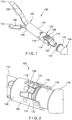
Fig 2 shows an enlarged perspective view of a portion of the system ofFig. 1 ; -
Fig. 3 shows a cross-sectional perspective view of a portion of the system ofFig. 1 ; -
Fig. 4 shows a longitudinal cross-sectional view of a portion of the system ofFig. 1 ; -
Fig. 5 shows a side view of a coupler according to the system ofFig. 1 ; -
Fig. 6 shows a cross-sectional view of the coupler according the system ofFig. 1 ; -
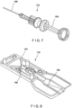
Fig. 7 shows a perspective view of an applicator according to the system ofFig. 1 ; -
Fig. 8 shows a perspective view of a cartridge according to the system ofFig. 1 ; -
Fig. 9 shows a partially transparent side view of the coupler and a bushing of the system ofFig. 1 , upon loading of a clip onto the applicator; -
Fig. 10 shows a partially transparent side view of the coupler and the bushing of the system ofFig. 1 , during a deployment of the clip; and -
Fig. 11 shows a partially transparent side view of the coupler and the bushing system ofFig. 1 , upon deployment of the clip. - The present disclosure may be further understood with reference to the following description and the appended drawings, wherein like elements are referred to with the same reference numerals. The present disclosure relates to a clipping system and, in particular, relates to a reloadable endoscopic clipping system, in which a clip may be loaded onto a distal end of an applicator prior to an endoscopic procedure. Once a clip has been deployed at a desired target area in the body, the applicator may be reloaded with a new clip. Although shed parts (e.g., parts that are left in a body upon deployment of the clip) generally pass naturally from the body shed parts may become trapped in larger defects after closure.
- Exemplary embodiments of the present disclosure comprise a clip including clip arms slidable within a capsule to move between an open configuration and a closed configuration to clip tissue, as desired. A proximal end of the capsule is loaded onto a bushing at a distal end of an applicator via a coupler which facilitates a releasable connection with the applicator while also minimizing or eliminating the potential for shed parts upon deployment of the clip. Prior to loading of the clip onto the applicator the coupler is coupled to the capsule. Upon deployment of the clip, however, the coupler is detached from the capsule to be removed from the body along with the applicator. It will be understood by those of skill in the art that the terms proximal and distal as used herein, are intended to refer to a direction toward and away from, respectively, a user of the device.
- As shown in
Figs. 1 - 11 , areloadable clipping system 100 comprises aclip 102 configured to be loaded onto anapplicator 104 via acoupler 106 prior to insertion of thesystem 100 into a body to clip target tissue therein. Theclip 102 includes a pair ofclip arms 108, proximal ends of which are slidably received within acapsule 110 so that theclip arms 108 may move between an open configuration, in whichdistal ends 112 of theclip arms 108 are separated from one another, and a closed configuration, in whichdistal ends 112 are drawn toward one another to grip tissue. Thecoupler 106 includes a pair ofretention arms 114, which maintain a coupling between theclip 102 and, for example, a bushing 118 of theapplicator 104 while theclip 102 is moved between the open and closed configurations during use. Thecoupler 106 also include a pair ofdeployment arms 116, which facilitate deployment of theclip 102 from theapplicator 104. In particular, as will be described in further detail below, prior to loading of theclip 102 onto theapplicator 104, thecoupler 102 is coupled to thecapsule 110 of theclip 102 to facilitate loading of theclip 102 onto theapplicator 104 via theretention arms 114. - During deployment of the
clip 102 over a target portion of tissue in the body, however, theclip 102 is moved proximally relative to theapplicator 104 so that thedeployments arms 116 are moved radially outward with respect to a longitudinal axis of thesystem 100, disengaging thecoupler 106 from thecapsule 110 so that thecoupler 106 may be removed from the body along with theapplicator 104. Thecoupler 106 stays attached to thebushing 118 even after detaching from thecapsule 110. Thecoupler 106 will then have to be removed from thebushing 118 by a user prior to loading anew clip 102 onto thesame applicator 104. Thus,deployment 102 of theclip 102 does not leave any shed parts in the body. Theapplicator 104 is configured so that, after deployment of theclip 102, anew clip 102 may be loaded onto theapplicator 104 so that thesame applicator 104 may be used to deliver thenew clip 102 to a second portion of target tissue in the body. Eachclip 102 according to this embodiment is stored in acartridge 120, which facilitates loading of theclip assembly 102 onto theapplicator 104. - As shown in
Figs. 1-4 , theclip 102 includes the pair ofclip arms 108, proximal ends of which are, in this embodiment, connected to one another via ayoke 122 slidably received within thecapsule 110. In this embodiment, theclip arms 108 are biased toward the open configuration so that, when not constrained by thecapsule 110, theclip arms 108 move under their natural bias to the open configuration in which the distal ends 112 of theclip arms 106 spread apart from one another to receive tissue therebetween. When theclip arms 108 are drawn into thecapsule 110, thecapsule 110 constrains theclip arms 108, holding the distal ends 112 together so that tissue may be gripped therebetween. Theyoke 122 is longitudinally slidable within thecapsule 110 to move theclip arms 108 proximally and distally relative to thecapsule 110 between the open and closed configurations. - Each of the
clip arms 108 extends from a proximal end connected to theyoke 122 to thedistal end 112. The distal ends 112 of one or both of theclip arms 108 may include a tip extending laterally inward toward theother clip arm 108 with the tips including, for example, teeth, protrusions, spikes or other structures configured to grip tissue between the distal ends 112. One or both of theclip arms 108 may also include a locking feature configured to lock theclip arms 108 in the tissue gripping configuration after target tissue has been gripped as desired by theclip arms 108. In one embodiment, one or both of theclip arms 108 includes a locking tab extending laterally outward therefrom configured to engage a portion of thecapsule 110 when theclip arms 108 have been drawn into thecapsule 110 by a predetermined distance. For example, the locking tabs may be received within correspondingly sized, shaped and positioned locking windows extending laterally into or through a wall of thecapsule 110 to lock theclip arms 108 relative to thecapsule 110, in the tissue gripping configuration. - The
yoke 122 is connected to the proximal ends of theclip arms 108 and is configured to be connected to an enlargeddistal end 126 of acontrol member 124 of theapplicator 104. In one embodiment, theyoke 122 of this embodiment includes aproximal portion 128 and a distal portion (not shown) configured to be separated from one another when subject to a force exceeding a predetermined threshold value. Theproximal portion 128 and distal portion may, for example, be connected to one another via a welding, a decreased diameter portion, or an adhesive that breaks or otherwise separates when pre-determined force is exerted thereon. The distal portion may engage proximal portions of theclip arms 108 via, for example, a pair of protrusions extending through openings along proximal portions of theclip arms 108 so that theclip arms 108 are held in position relative to one another. - The
proximal portion 128 is configured to engage the enlargeddistal end 126 of thecontrol member 124. In one embodiment, theproximal portion 128 includes acavity 130 sized and shaped to receive the enlargeddistal end 126 and alongitudinal slot 132 extending proximally from thecavity 130 to aproximal end 134 of theyoke 122. Thelongitudinal slot 132 is sized and shaped to receive a portion of thecontrol member 124 extending proximally from the enlargeddistal end 126. - In one embodiment, an opening of the
longitudinal slot 132 at theproximal end 134 includes anangled surface 136 tapering toward a distal end thereof to facilitate insertion of the enlargeddistal end 126 distally through thelongitudinal slot 132 and into thecavity 130 during loading theclip 102 onto theapplicator 104. Thecavity 130 and thelongitudinal slot 132 are configured so that, once the enlargeddistal end 126 has been forced through theslot 132 into thecavity 130, theslot 132 retracts in diameter to prevent the enlargeddistal end 126 from being proximally withdrawn therefrom. Thus, longitudinal movement of thecontrol member 124 relative to thecapsule 110 moves theclip arms 108 between the open and the closed configurations. - The
capsule 110 extends longitudinally from aproximal end 138 to adistal end 140 and includes achannel 142 extending longitudinally therethrough. Thechannel 142 is sized and shaped to slidably receive theyoke 122 and theclip arms 108 therein. As described above, thecapsule 110 of this embodiment also includes locking structures (e.g., locking recesses or windows) for engaging corresponding locking features (e.g., locking tabs) of theclip arms 108. Thecapsule 110, in this embodiment, also includesopenings 144 extending through a wall thereof along theproximal end 138. Theopenings 144 are sized, shaped and configured to receive anengaging feature 146 of thedeployment arms 116 of thecoupler 106, as will be described in further detail below. - As described above, the
coupler 106 is coupled to theproximal end 138 of thecapsule 110 of theclip 102 prior to loading of theclip 102 onto theapplicator 104. In this embodiment, thecoupler 106 includes adistal portion 148 sized and shaped to be mounted over thecapsule 110, the pair ofretention arms 114 and the pair ofdeployment arms 116 extending proximally therefrom. Thecoupler 106, in this embodiment, may be formed of a stainles steel material and manufactured via, for example, metal stamping and rolling. As shown inFigs. 5-6 , in one embodiment, thedistal portion 148 may be substantially ring shaped, with theretention arms 114 substantially diametrically opposing one another and thedeployment arms 116 substantially diametrically opposing one another so that the retention arms and thedeployment arms 116 alternate about a periphery of thecoupler 106. In one embodiment, each of theretention arms 114 and thedeployment arms 116 may be equally spaced from one another. - Each
retention arm 114 includes afirst protrusion 150 extending laterally (e.g., radially inward) from an interior surface 154 (i.e., a surface of theretention arms 114 which, in an operative configuration, faces toward the bushing 118) thereof along a distal portion thereof and asecond protrusion 152 extending laterally (e.g., radially inward) from theinterior surface 154 proximally of thefirst protrusion 150. Thefirst protrusion 150 is sized, shaped and configured so that thecoupler 106 may be slid distally over theproximal end 138 of thecapsule 110 until thefirst protrusion 150 engages a portion of thecapsule 110, preventing thecoupler 106 from being moved any further distally relative thereto. Proximally of thesecond protrusion 152, theretention arm 114 includes aretention feature 156 configured as a protrusion extending laterally (e.g., radially inward) from theinterior surface 154 to, as will be described in further detail below, engage a portion of thebushing 118 during a loading of theclip 102 onto theapplicator 104. Theretention feature 156 may be shaped to facilitate a distal insertion of a portion of thebushing 118 therepast (or a proximal movement of thecoupler 106 over a portion of the bushing 118) during loading of theclip 102. In particular, theretention feature 156 may include anangled surface 158 tapering toward a proximal end thereof. - The
second protrusion 152 is configured such that, when theretention feature 156 engages a corresponding portion of thebushing 118, adistal end 172 of thebushing 118 engages thesecond protrusion 152, preventing thebushing 118 from being moved any further distally relative to thecoupler 106 during loading of theclip 102 onto theapplicator 104 and during opening and closing of theclip 102. A depth of the second protrusion 152 (i.e., a distance by which the second protrusion extends from the interior surface 154) is, however, selected so that, when a pre-determined compressive force is applied to thecoupler 106 during deployment of theclip 102 thesecond protrusion 152 is permitted to move proximally past thedistal end 172 of the bushing 118 (i.e., thesecond protrusion 152 is sized and shaped to dictate deployment force), as will be described in further detail below. Additionally, thesecond protrusion 152 serves as a retention feature for thecoupler 106 to stay engaged with thebushing 118 after thecouple 106 separates from thecapsule 110. It will be understood by those of skill in the art, that in some embodiments, theretention arms 114 may include more than one of each of thefirst protrusion 150,second protrusion 152 and theretention feature 156. - Each
deployment arm 116 includes theengaging feature 146 along a distal portion thereof. Theengaging feature 146 extends laterally inward from aninterior surface 160 of the deployment arm 116 (i.e., a surface of thedeployment arm 116 facing toward thebushing 118, in the operative configuration). Theengaging feature 146 is configured so that, when thecoupler 106 is assembled with theclip 102 prior to loading of theclip 102, thecoupler 106 may be moved distally over theproximal end 138 of thecapsule 110 until theengaging feature 146 is snapped into a corresponding one of theopenings 144 of thecapsule 110 and thefirst protrusion 150 engages thecapsule 110 preventing further distal movement of thecoupler 106 relative to thecapsule 110. - In this embodiment, the
engaging feature 146 includes anangled surface 162, which tapers toward a distal end thereof, to facilitate distal movement of thecoupler 106 over thecapsule 110 during the assembly of thecoupler 106 with thecapsule 110. It will be understood by those of skill in the art that, once thecoupler 106 is assembled with theclip 102, theangled surface 162 of theengaging feature 146 prevents a proximal movement of thecoupler 106 relative to thecapsule 110, while thefirst projections 150 prevents a distal movement of thecoupler 106 relative to thecapsule 110. - Each
deployment arm 116 also includes acurved portion 164 proximal of theengaging feature 146. Thecurved portion 164 is curved inward toward a longitudinal axis of thecoupler 106 so that a distance between thecurved portions 164 of the pair ofdeployment arms 116 is smaller than a distance between remaining portions of thedeployment arms 116. For example, a diameter between thecurved portions 164 is smaller than a diameter of a remaining portion of thecoupler 106. Thus, as will be described in further detail below, when thecurved portions 164 are moved proximally over a portion of thebushing 118, thedeployment arms 116 deflect radially outward so that the engagingfeatures 146 are disengaged from theopenings 144 of thecapsule 110. - Although the
deployment arms 116 are shown and described as includingcurved portions 164, it will be understood by those of skill in the art that thedeployment arms 116 may include other structure or features for engaging thebushing 118 to cause an outward deflection or deformation of thedeployment arms 116. It will also be understood by those of skill in the art that a force required to deflect or deform thedeployment arms 116 may be controlled by adjusting a length and/or width of thedeployment arms 116 or a distance between thecurved portions 164. It will also be understood by those of skill in the art that a depth of the engaging features 146 (i.e., a distance by which theengaging feature 146 extends from the interior surface 160) may also be adjusted to increase or decrease a retention of thecoupler 106 onto thecapsule 110. - As shown in
Fig. 7 , theapplicator 104 includes aflexible member 166 such as, for example, a catheter extending from a proximal end connected to ahandle portion 168 that remains outside of the body during the clipping of target tissue, to a distal end including, for example, thebushing 118 for connecting theapplicator 104 to theclip 102. Thecontrol member 124 extends through theflexible member 166 from a proximal end connected to thehandle portion 168, which includes actuators for controlling a movement of theclip 102 once theclip 102 has been loaded onto theapplicator 104, to the enlargeddistal end 126. - In an embodiment, the
bushing 118 is connected to the distal end of theflexible member 166 and is configured to be connected to theclip 102 via thecoupler 106, which is preassembled with theclip 102. Thebushing 118 extends from aproximal end 170 to adistal end 172 and includes achannel 174 extending therethrough so that, when thebushing 118 is coupled to theclip 102 via thecoupler 106, thechannel 174 of thebushing 118 is substantially aligned with thechannel 142 of thecapsule 110. In an embodiment, thedistal end 172 of thebushing 118 includes aprojection 176 extending about a periphery of thebushing 118, theprojection 176 extending radially outward from anexterior surface 178 along thedistal end 172. Adistal end 180 of theprojection 176 is tapered to facilitate insertion of theprojection 176 distally past theretention feature 156. Theproximal end 182 of theprojection 176 is configured to engage theretention feature 156. As described above, when theclip 102 is loaded onto theapplicator 104 by moving theprojection 176 distally past theretention feature 156, theprojection 176 is received between thesecond projection 152 and theretention feature 156, holding theprojection 176 therebetween during use of the clip 102 - e.g., opening and closing of theclip arms 108. - Prior to being loaded on the
applicator 104, theclip 102 of this embodiment is stored in thecartridge 120, which is configured to facilitate loading of theclip assembly 102 on theapplicator 104. Thecartridge 120, as shown inFig. 8 , is configured as a storage container including abase 184 and lid (not shown), within which aspace 186 sized and shaped to house theclip 102 is defined. It should be noted that althoughFig. 8 shows only thebase 184 of thecartridge 120, a corresponding lid is coupled to the base 184 to completely enclose theclip 102. In this embodiment, theclip 102 is stored within thecartridge 120 in the open configuration, with thecoupler 106 preassembled with thecapsule 110. Extending proximally from thespace 186 is alongitudinal slot 188 through which the distal portion of theapplicator 104 is inserted to be coupled to theclip assembly 102, as will be described in further detail below. - During loading of the
clip 102 onto theapplicator 104, a distal portion of theapplicator 104, including thebushing 118, is inserted through thelongitudinal slot 188 of thecartridge 120, which houses the assembledclip 102 andcoupler 106. As described above, thecoupler 106 is mounted over theproximal end 138 of thecapsule 110 such that the engagingfeatures 146 of thedeployment arms 116 are received within the correspondingopenings 144 of thecapsule 110 and thefirst projections 150 engage a portion of thecapsule 110. In one embodiment, thedistal end 172 of thebushing 118 may be moved distally between theretention arms 114 of thecoupler 106 so that theprojection 176 is moved distally therepast and is received between thesecond projection 152 and theretention feature 156, as shown inFig. 9 . Once thebushing 118 is coupled to theclip 102 via thecoupler 106, thecontrol member 124 is moved distally relative to thebushing 118 to be coupled to theclip arms 108 via theyoke 122. In particular, the enlargeddistal end 126 of thecontrol member 124 may be inserted into thecavity 130 of theyoke 122 via theslot 132. - In another embodiment, the
control member 124 may be coupled to theyoke 122 prior to coupling thebushing 118 to thecoupler 106 so that upon coupling thecontrol member 124 to theyoke 122, thecapsule 110 may be moved proximally relative to thebushing 118 via a proximal motion of thecontrol member 124 so that thecoupler 106 is moved proximally over thedistal end 172 of thebushing 118 to engage theprojection 176. Once both thecontrol member 124 and thebushing 118 have been coupled to theclip 102, loading of theclip 102 onto theapplicator 104 is complete, and theclip 102 may be drawn proximally out of the cartridge via thelongitudinal slot 188. - In use, after the
clip 102 has been loaded onto theapplicator 104, theclip 102, in the closed configuration, is inserted into the body to a location adjacent to target tissue via, for example, a working channel of an endoscope. Once theclip 102 has reached the target tissue, theclip 102 is moved toward the open configuration to receive the target tissue between the distal ends 112 of theclip arms 108. Theclip 102 may be moved between the open and the closed configurations until the target tissue has been clipped between theclip arms 108, as desired. Once theclip 102 is in the closed configuration clipping the target tissue as desired, the control member 124 (e.g., via actuators of the handle portion 168) is moved proximally with respect to thecapsule 110 until locking features of theclip arms 108 engage corresponding locking structures of thecapsule 110, locking theclip arms 108 relative to thecapsule 110 in the closed configuration. - To free the
clip 102 from theapplicator 104, thecontrol member 124 is drawn further proximally until thecoupler 106 is drawn proximally against thebushing 118 and a compressive load on thecoupler 106 exceeds a predetermined threshold value, forcing thesecond protrusion 152 proximally past theprojection 176 of thebushing 118 while also causing thecurved portions 164 of thedeployment arms 116 to slide proximally overprojection 176, as shown inFig. 10 . As thecurved portions 164 move proximally over theprojection 176, thedeployment arms 116 are deflected radially outward so that the engagingfeatures 146 of thedeployment arms 116 are moved out of engagement with theopenings 144 of thecapsule 110 and thesecond protrusion 152 is moved proximally past theproximal end 182 of theprojection 176. - As shown in
Fig. 11 , thesecond protrusion 152 engages theproximal end 182 of the projection so that thecoupler 106 remains engaged to thebushing 118 while being disengaged from thecapsule 110. The user continues to exert proximal force on thecontrol member 124 until theyoke 122 breaks, fails or otherwise separates, releasing theclip 102, from thecontrol member 124. Thus, theapplicator 104, with thecoupler 106 coupled thereto, may be removed from thebody 102, leaving just theclip 102 in place clipping the target tissue. Theentire applicator 104, including thecontrol member 124, thecoupler 106 and theproximal portion 128 of theyoke 122 may then be withdrawn proximally from the body leaving theclip 102 clipped over the target tissue. If so desired, anew clip 102 may be loaded onto theapplicator 104, in the same manner as described above, so that thesystem 100 may then be used to clip a second portion of tissue. This process may be repeated using thesame applicator 104 as many times as needed or desired. - It will be apparent to those skilled in the art that various modifications may be made in the present disclosure, without departing from the scope of the disclosure.
- The following aspects are preferred embodiments of the present invention.
- 1. A clipping system for treating tissue, comprising:
- a clip including a pair of clip arms, each of the clip arms extending from a proximal end to a distal end, proximal ends of the clip arms slidably received within a channel of a capsule to be moved between an open configuration and a closed configuration, a proximal end of the capsule including a pair of openings extending through a wall thereof;
- a coupler mounted over the proximal end of the capsule and including a pair of deployment arms and a pair of retention arms, the deployment arms having engaging features received within the openings of the capsule; and
- an applicator including an elongated flexible member and a control member extending therethrough, the control member including a distal end configured to be connected to the clip arms to move the clip arms between the open configuration and the closed configuration, a distal end of the elongated flexible member including a projection extending about a periphery of the distal end thereof to engage corresponding retaining features of the retention arms, the deployment arms and the projection configured so that, when a pre-determined compressive force is applied to the coupler during deployment of the clip, the deployment arms slide proximally along the projection such that the deployment arms deflect away from the bushing to disengage the engaging features therefrom so that the coupler is separable from the capsule.
- 2. The system of aspect 1, wherein the retention features of the retention arms extend laterally inwardly from an interior surface of the retention arms toward a longitudinal axis of the coupler so that, to couple the bushing to the coupler, the bushing is inserted distally between the retention arms until the projection is moved distally past the retention features.
- 3. The system of any of aspects 1-2, wherein the deployment arms include curved portions proximal of the engaging features, the curved portions curved inward toward a longitudinal axis of the coupler so that a diameter of the coupler between the curved portions is smaller than a diameter of the coupler along a remaining portion thereof.
- 4. The system of any of aspects 1-3, wherein each of the retention arms include a first protrusion extending laterally inward from an interior surface thereof, the first protrusion engaging a portion of the capsule to prevent a proximal movement of the capsule relative to the coupler.
- 5. The system of any of aspects 1-4, wherein each of the retention arms include a second protrusion extending laterally inward from an interior surface thereof, the second protrusion positioned distally of the retention features so that, when the bushing is coupled to the coupler, the projection is received between the second protrusion and the engaging features.
- 6. The system of aspect 5, wherein a depth of the second protrusion is selected so that, when the pre-determined compressive force is applied to the coupler, the second protrusion is permitted to slide proximally past the protrusion to engage a proximal end of the protrusion.
- 7. The system of any of aspects 1-6, wherein the coupler includes a distal portion extending about the proximal end of the capsule such that the pair of deployment arms and the pair of retention arms extend proximally therefrom.
- 8. The system of aspect 7, wherein the retention arms diametrically oppose one another and the deployment arms diametrically oppose one another.
- 9. The system of any of aspects 1-8, wherein the control member is connectable to the clip arms via a yoke configured to separate a proximal portion thereof, which is coupleable to the control member, from a distal portion thereof, which is connected to the proximal ends of the clip arms, when subject to a predetermined threshold force
- 10. A clip device for treating tissue, comprising:
- a clip including a pair of clip arms, each of the clip arms extending from a proximal end to a distal end, proximal ends of the clip arms slidably received within a channel of a capsule to be moved between an open configuration and a closed configuration, a proximal end of the capsule including a pair of openings extending through a wall thereof; and
- a coupler mounted over the proximal end of the capsule via a pair of deployment arms including engaging features extending laterally inward from an interior surface thereof to engage the pair of openings of the capsule, the coupler including retention arms configured to engage a corresponding portion of an applicator, the deployment arms configured so that, when a pre-determined compressive force is applied to the coupler, the deployment arms are proximally slidable along the corresponding portion of the applicator to deflect the deployment arms out of engagement with the capsule so that the coupler is separable from the capsule.
- 11. The device of aspect 10, wherein the retention arms include retention features extending laterally inwardly from an interior surface of the retention arms toward a longitudinal axis of the coupler for engaging a corresponding portion of an applicator.
- 12. The device of any of aspects 10-11, wherein the deployment arms include curved portions proximal of the engaging features, the curved portions curved inward toward a longitudinal axis of the coupler so that a diameter of the coupler between the curved portions is smaller than a diameter of the coupler along a remaining portion thereof.
- 13. The device of any of aspects 10-12, wherein each of the retention arms include a first protrusion extending laterally inward from an interior surface thereof, the first protrusion engaging a portion of the capsule to prevent a proximal movement of the capsule relative to the coupler.
- 14. The device of any of aspects 10-13, wherein each of the retention arms include a second protrusion extending laterally inward from an interior surface thereof, the second protrusion positioned distally of the retention features so that the corresponding portion of the applicator is receivable therebetween.
- 15. The device of aspect 14, wherein a depth of the second protrusion is selected so that, when the pre-determined compressive force is applied to the coupler, the second protrusion is permitted to slide proximally past the corresponding portion of the applicator.
Claims (12)
- A clipping system for treating tissue, comprising:a clipping apparatus including a pair of clip arms slidably received in a capsule, the capsule including windows extending through a proximal end thereof;a coupler mounted over the proximal end of the capsule, the coupler including a pair of retention arms each having a retaining feature and a pair of deployment arms each having an engaging feature configured to be received within the windows of the capsule; andan applicator having a distal end including a projection extending about a periphery thereof, the projection configured to be engaged by the retaining features to couple the coupler to the distal end, and the deployment arms being configured so that, when a compressive force exerted on the coupler exceeds a predetermined threshold, the deployment arms slide proximally along the projection and deflect radially outward to disengage the engaging features from the capsule so that the coupler separates from the capsule while remaining coupled to the distal end of the applicator.
- The system of claim 1, wherein the retaining features extend laterally inwardly from an interior surface of the retention arm toward a longitudinal axis of the coupler so that, to couple the distal end to the coupler, the distal end is inserted distally until the projection is moved distally past the retaining features.
- The system of claim 1, wherein the deployment arms include curved portions proximal of the engaging features, the curved portions curving inward toward a longitudinal axis of the coupler.
- The system of claim 1, wherein each of the retention arms includes a first protrusion extending laterally inward from an interior surface thereof, the first protrusion engaging a corresponding portion of the capsule to prevent proximal movement of the capsule relative to the coupler.
- The system of claim 4, wherein each of the retention arms includes a second protrusion extending laterally inward from the interior surface thereof, the second protrusion being positioned distally of the retaining feature so that, when the coupler is coupled to the distal end, the projection is received between the second protrusion and the engaging feature.
- The system of claim 5, wherein a depth of the second protrusion is selected so that, when the compressive force is applied to the coupler, the second protrusion is permitted to slide proximally past the projection until the projection engages a proximal end of the second protrusion.
- The system of claim 1, wherein the coupler includes a distal portion extending about the proximal end of the capsule such that the deployment arms and the retention arms extend proximally therefrom.
- The system of claim 7, wherein the retention arms diametrically oppose one another and the deployment arms diametrically oppose one another.
- The system of claim 1, wherein a control member extending through an elongated flexible member of the applicator is configured to be coupled to the clip arms via a yoke, the yoke is configured to separate a proximal portion thereof, which is coupleable to the control member, from a distal portion thereof, which is connected to proximal ends of the clip arms, when subject to a predetermined threshold force.
- The system of claim 1, wherein the distal end of the applicator further comprises a bushing including the projection configured to be engaged by the retaining features to couple the coupler to the bushing.
- The system of claim 1, wherein the coupler is configured to be coupled to the capsule prior to loading of the clip apparatus onto the distal end of the applicator.
- The system of claim 1, wherein the coupler is configured to disengage from the capsule during deployment while remaining attached to the distal end of the applicator so that the coupler may be removed from a living body along with the applicator.
Applications Claiming Priority (3)
| Application Number | Priority Date | Filing Date | Title |
|---|---|---|---|
| US201962877879P | 2019-07-24 | 2019-07-24 | |
| EP20739517.9A EP3927250B1 (en) | 2019-07-24 | 2020-06-18 | Clipping system for treating tissue |
| PCT/US2020/038542 WO2021015902A1 (en) | 2019-07-24 | 2020-06-18 | Non-shedding coupling method and system for reloadable hemostasis clip |
Related Parent Applications (2)
| Application Number | Title | Priority Date | Filing Date |
|---|---|---|---|
| EP20739517.9A Division EP3927250B1 (en) | 2019-07-24 | 2020-06-18 | Clipping system for treating tissue |
| EP20739517.9A Division-Into EP3927250B1 (en) | 2019-07-24 | 2020-06-18 | Clipping system for treating tissue |
Publications (2)
| Publication Number | Publication Date |
|---|---|
| EP4501250A2 true EP4501250A2 (en) | 2025-02-05 |
| EP4501250A3 EP4501250A3 (en) | 2025-04-16 |
Family
ID=71575799
Family Applications (2)
| Application Number | Title | Priority Date | Filing Date |
|---|---|---|---|
| EP20739517.9A Active EP3927250B1 (en) | 2019-07-24 | 2020-06-18 | Clipping system for treating tissue |
| EP24209383.9A Pending EP4501250A3 (en) | 2019-07-24 | 2020-06-18 | Non-shedding coupling method and system for reloadable hemostasis clip |
Family Applications Before (1)
| Application Number | Title | Priority Date | Filing Date |
|---|---|---|---|
| EP20739517.9A Active EP3927250B1 (en) | 2019-07-24 | 2020-06-18 | Clipping system for treating tissue |
Country Status (8)
| Country | Link |
|---|---|
| US (3) | US11690634B2 (en) |
| EP (2) | EP3927250B1 (en) |
| JP (2) | JP7297938B2 (en) |
| KR (2) | KR20250023609A (en) |
| CN (2) | CN118902532A (en) |
| AU (1) | AU2020316905B2 (en) |
| CA (1) | CA3139563C (en) |
| WO (1) | WO2021015902A1 (en) |
Families Citing this family (4)
| Publication number | Priority date | Publication date | Assignee | Title |
|---|---|---|---|---|
| JP7720479B2 (en) * | 2021-09-09 | 2025-08-07 | ボストン サイエンティフィック サイムド,インコーポレイテッド | Collet-Deployed Hemostatic Clip |
| CN115137438B (en) * | 2022-06-14 | 2024-03-22 | 江苏唯德康医疗科技有限公司 | Clamping device and anastomosis clamp for endoscope |
| KR20250024993A (en) * | 2022-09-27 | 2025-02-20 | 보스톤 싸이엔티픽 싸이메드 인코포레이티드 | Locking features for hemostatic clips |
| WO2026028397A1 (en) * | 2024-08-01 | 2026-02-05 | オリンパスメディカルシステムズ株式会社 | Cartridge system |
Family Cites Families (12)
| Publication number | Priority date | Publication date | Assignee | Title |
|---|---|---|---|---|
| EP3878381A3 (en) | 2003-09-30 | 2021-11-10 | Boston Scientific Scimed, Inc. | Through the scope tension member release clip |
| AU2005203521B2 (en) * | 2004-09-28 | 2011-11-17 | Ethicon Endo-Surgery | Applier having automated release of surgical device |
| JP4758173B2 (en) * | 2004-12-24 | 2011-08-24 | オリンパス株式会社 | Ligation device |
| US8162959B2 (en) * | 2007-05-03 | 2012-04-24 | Boston Scientific Scimed, Inc. | Single stage hemostasis clipping device |
| US8267944B2 (en) * | 2008-08-29 | 2012-09-18 | Tyco Healthcare Group Lp | Endoscopic surgical clip applier with lock out |
| US20140236152A1 (en) * | 2011-08-23 | 2014-08-21 | Aesculap Ag | Electrosurgical device and methods of manufacture and use |
| JP2015532859A (en) * | 2012-09-24 | 2015-11-16 | ボストン サイエンティフィック サイムド,インコーポレイテッドBoston Scientific Scimed,Inc. | Solution mechanism for hemostatic clips |
| CN104546055A (en) | 2013-10-25 | 2015-04-29 | 常州乐奥医疗科技有限公司 | Novel digestive tract hemostatic clamp capable of being repeatedly closed |
| US11020125B2 (en) * | 2016-08-22 | 2021-06-01 | Boston Scientific Limited | Hemostasis reloadable clipping device with sleeve engagement |
| EP4344656A3 (en) * | 2016-11-22 | 2024-06-05 | Boston Scientific Medical Device Limited | Hemostasis reloadable clip release mechanism |
| WO2018106710A1 (en) * | 2016-12-06 | 2018-06-14 | Boston Scientific Scimed, Inc. | Compressive coupler for reloadable hemostasis clipping device |
| CN111163711B (en) | 2017-11-28 | 2023-09-08 | 波士顿科学国际有限公司 | Self-aligning pull wire for reloadable hemostatic clip device |
-
2020
- 2020-06-18 CN CN202411308915.9A patent/CN118902532A/en active Pending
- 2020-06-18 AU AU2020316905A patent/AU2020316905B2/en active Active
- 2020-06-18 WO PCT/US2020/038542 patent/WO2021015902A1/en not_active Ceased
- 2020-06-18 KR KR1020257004426A patent/KR20250023609A/en active Pending
- 2020-06-18 JP JP2021570295A patent/JP7297938B2/en active Active
- 2020-06-18 CA CA3139563A patent/CA3139563C/en active Active
- 2020-06-18 EP EP20739517.9A patent/EP3927250B1/en active Active
- 2020-06-18 KR KR1020217031577A patent/KR102768430B1/en active Active
- 2020-06-18 CN CN202080049285.1A patent/CN114080192B/en active Active
- 2020-06-18 EP EP24209383.9A patent/EP4501250A3/en active Pending
- 2020-06-18 US US16/905,765 patent/US11690634B2/en active Active
-
2023
- 2023-05-10 US US18/315,124 patent/US12127746B2/en active Active
- 2023-06-14 JP JP2023097624A patent/JP2023113940A/en active Pending
-
2024
- 2024-09-30 US US18/902,199 patent/US20250025184A1/en active Pending
Also Published As
| Publication number | Publication date |
|---|---|
| CN114080192A (en) | 2022-02-22 |
| US20230301662A1 (en) | 2023-09-28 |
| US20250025184A1 (en) | 2025-01-23 |
| CA3139563C (en) | 2024-06-25 |
| JP2023113940A (en) | 2023-08-16 |
| US12127746B2 (en) | 2024-10-29 |
| AU2020316905B2 (en) | 2022-12-01 |
| EP3927250B1 (en) | 2025-02-26 |
| JP7297938B2 (en) | 2023-06-26 |
| CN114080192B (en) | 2024-10-01 |
| CA3139563A1 (en) | 2021-01-28 |
| US20210022744A1 (en) | 2021-01-28 |
| KR102768430B1 (en) | 2025-02-18 |
| AU2020316905A1 (en) | 2021-09-30 |
| WO2021015902A1 (en) | 2021-01-28 |
| CN118902532A (en) | 2024-11-08 |
| EP4501250A3 (en) | 2025-04-16 |
| EP3927250A1 (en) | 2021-12-29 |
| JP2022534250A (en) | 2022-07-28 |
| KR20250023609A (en) | 2025-02-18 |
| US11690634B2 (en) | 2023-07-04 |
| KR20210135277A (en) | 2021-11-12 |
Similar Documents
| Publication | Publication Date | Title |
|---|---|---|
| US12127746B2 (en) | Non-shedding coupling method and system for reloadable hemostasis clip | |
| US11678889B2 (en) | Partially oval capsule for reloadable hemostasis clipping device | |
| US12102335B2 (en) | Reloadable clip with a flaring capsule deformation | |
| US12102336B2 (en) | Crimp attachment of clip for reloadable hemostasis device |
Legal Events
| Date | Code | Title | Description |
|---|---|---|---|
| PUAI | Public reference made under article 153(3) epc to a published international application that has entered the european phase |
Free format text: ORIGINAL CODE: 0009012 |
|
| STAA | Information on the status of an ep patent application or granted ep patent |
Free format text: STATUS: REQUEST FOR EXAMINATION WAS MADE |
|
| 17P | Request for examination filed |
Effective date: 20241124 |
|
| AC | Divisional application: reference to earlier application |
Ref document number: 3927250 Country of ref document: EP Kind code of ref document: P |
|
| AK | Designated contracting states |
Kind code of ref document: A2 Designated state(s): AL AT BE BG CH CY CZ DE DK EE ES FI FR GB GR HR HU IE IS IT LI LT LU LV MC MK MT NL NO PL PT RO RS SE SI SK SM TR |
|
| PUAL | Search report despatched |
Free format text: ORIGINAL CODE: 0009013 |
|
| AK | Designated contracting states |
Kind code of ref document: A3 Designated state(s): AL AT BE BG CH CY CZ DE DK EE ES FI FR GB GR HR HU IE IS IT LI LT LU LV MC MK MT NL NO PL PT RO RS SE SI SK SM TR |
|
| RIC1 | Information provided on ipc code assigned before grant |
Ipc: A61B 17/128 20060101AFI20250313BHEP |
|
| GRAP | Despatch of communication of intention to grant a patent |
Free format text: ORIGINAL CODE: EPIDOSNIGR1 |
|
| STAA | Information on the status of an ep patent application or granted ep patent |
Free format text: STATUS: GRANT OF PATENT IS INTENDED |
|
| INTG | Intention to grant announced |
Effective date: 20260211 |
|
| GRAS | Grant fee paid |
Free format text: ORIGINAL CODE: EPIDOSNIGR3 |
|
| GRAA | (expected) grant |
Free format text: ORIGINAL CODE: 0009210 |
|
| STAA | Information on the status of an ep patent application or granted ep patent |
Free format text: STATUS: THE PATENT HAS BEEN GRANTED |