EP4501246A2 - Drill guide assembly - Google Patents
Drill guide assembly Download PDFInfo
- Publication number
- EP4501246A2 EP4501246A2 EP24218986.8A EP24218986A EP4501246A2 EP 4501246 A2 EP4501246 A2 EP 4501246A2 EP 24218986 A EP24218986 A EP 24218986A EP 4501246 A2 EP4501246 A2 EP 4501246A2
- Authority
- EP
- European Patent Office
- Prior art keywords
- drill
- guide
- guide body
- extending
- bullet
- Prior art date
- Legal status (The legal status is an assumption and is not a legal conclusion. Google has not performed a legal analysis and makes no representation as to the accuracy of the status listed.)
- Pending
Links
Images





Classifications
-
- A—HUMAN NECESSITIES
- A61—MEDICAL OR VETERINARY SCIENCE; HYGIENE
- A61B—DIAGNOSIS; SURGERY; IDENTIFICATION
- A61B17/00—Surgical instruments, devices or methods
- A61B17/16—Instruments for performing osteoclasis; Drills or chisels for bones; Trepans
- A61B17/17—Guides or aligning means for drills, mills, pins or wires
- A61B17/1739—Guides or aligning means for drills, mills, pins or wires specially adapted for particular parts of the body
- A61B17/1782—Guides or aligning means for drills, mills, pins or wires specially adapted for particular parts of the body for the hand or wrist
-
- A—HUMAN NECESSITIES
- A61—MEDICAL OR VETERINARY SCIENCE; HYGIENE
- A61B—DIAGNOSIS; SURGERY; IDENTIFICATION
- A61B17/00—Surgical instruments, devices or methods
- A61B17/56—Surgical instruments or methods for treatment of bones or joints; Devices specially adapted therefor
- A61B17/58—Surgical instruments or methods for treatment of bones or joints; Devices specially adapted therefor for osteosynthesis, e.g. bone plates, screws or setting implements
- A61B17/88—Osteosynthesis instruments; Methods or means for implanting or extracting internal or external fixation devices
- A61B17/8866—Osteosynthesis instruments; Methods or means for implanting or extracting internal or external fixation devices for gripping or pushing bones, e.g. approximators
-
- A—HUMAN NECESSITIES
- A61—MEDICAL OR VETERINARY SCIENCE; HYGIENE
- A61B—DIAGNOSIS; SURGERY; IDENTIFICATION
- A61B17/00—Surgical instruments, devices or methods
- A61B2017/0042—Surgical instruments, devices or methods with special provisions for gripping
-
- A—HUMAN NECESSITIES
- A61—MEDICAL OR VETERINARY SCIENCE; HYGIENE
- A61B—DIAGNOSIS; SURGERY; IDENTIFICATION
- A61B17/00—Surgical instruments, devices or methods
- A61B2017/0042—Surgical instruments, devices or methods with special provisions for gripping
- A61B2017/00438—Surgical instruments, devices or methods with special provisions for gripping connectable to a finger
Definitions
- the present invention is directed generally to a surgical system and, more particularly, to a drill guide to maintain particular positioning of bones in the thumb while maintaining the proper trajectory of a drill/drill bit.
- the carpometacarpal (CMC) joint is located at the base of the thumb and is responsible for providing a wide range of motion to the thumb.
- a CMC suspension is a procedure for repairing damage at the CMC joint.
- a surgeon will drill through the base of the first metacarpal and the proximal end of the second metacarpal.
- the surgeons can drill all the way through both the first and second metacarpals in one step.
- the first metacarpal is loose due to the removal of the trapezium before drilling, making the process of drilling at the desired location difficult. Further, when drilling in smaller bones, such as the first metacarpal, accuracy is critical.
- Embodiments of the present invention are directed to a drill guide for controlling the first metacarpal while maintaining the proper trajectory of a drill/drill bit.
- the drill guide includes a guide rail having an elongated shaft and a guide body with an aperture extending therethrough.
- the aperture is configured to receive the elongated shaft of the guide rail.
- the guide body also includes a drilling end with an aperture, creating an inner volume extending therethrough.
- the inner volume is configured to receive a drill bullet (which can be configured to fit a drill bit therein) therein.
- the drill bullet is rotatable within the inner volume of the drilling end of the guide body.
- the drill guide includes a guide rail having an elongated shaft extending along a first central longitudinal axis and a guide body with an aperture extending therethrough.
- the aperture is configured to receive the elongated shaft of the guide rail.
- the drill guide also includes a distal ring connected to the elongated shaft.
- a spike is attached to the distal ring and extends therefrom.
- a hook is also attached to the distal ring. The hook extends from the ring such that the hook and the spike extend from opposing positions along the distal ring.
- FIG. 1 shows an exploded perspective view schematic representation of a drill guide 10, according to an embodiment.
- the drill guide 10 comprises a proximal end 12 and a distal end 14.
- the drill guide 10 includes a guide body 16.
- the guide body 16 is configured to slide along a guide rail 18, which extends to the distal end 14.
- the guide rail 18 has an elongated shaft 20 extending toward the proximal end 12 of the drill guide 10.
- the guide rail 18 extends along a central longitudinal y 1 -y 1 axis.
- the guide rail 18 comprises a plurality of ridges 22 extending along at least a portion of a surface 24 of the guide rail 18.
- the guide rail 18 can have a distal ring 26 connected to the elongated shaft 20.
- the distal ring 26 has a hook 28 extending therefrom.
- the hook 28 is curved in the distal direction (but can curve in the proximal direction), extending substantially along a lateral x-x axis.
- the ring 26 is substantially planar along the lateral x-x axis.
- the guide rail 18 additionally includes a spike 30 extending from the ring 26.
- the spike 30 extends substantially along the lateral x-x axis.
- the spike 30 extends from the ring 26 in a direction opposing the hook 28 (but could extend in the same direction as the hook 28).
- the lateral x-x axis is substantially perpendicular to the central longitudinal y 1 -y 1 axis.
- FIG. 1 also shows that the spike 30 includes a sharp tip 32 extending in the proximal direction.
- the guide body 16 includes a trigger end 34 and a drilling end 36.
- the drilling end 36 of the guide body 16 includes an aperture 38 defining an inner volume 40 extending from a proximal surface 42 of the guide body 16 to a distal surface 44 of the guide body 16.
- the inner volume 40 extends along a central longitudinal y 2 -y 2 axis, which extending substantially parallel to the central longitudinal y 1 -y 1 axis.
- the sharp tip 32 of the spike 30 also extends along the central longitudinal y 2 -y 2 axis such that the sharp tip 32 is substantially aligned with the aperture 38 and/or inner volume 40 of the drilling end 36 of the guide body 16.
- the inner volume 40 of the drilling end 36 of the guide body 16 is configured to receive a drill bullet 46.
- the drill bullet 46 includes a shaft 48 extending proximally along the central longitudinal y 2 -y 2 axis and a pair of arms 50 extending distally from the shaft 48.
- the drilling end 36 of the guide body 16 can also include a locking mechanism 52 that maintains the drill bullet 46 in the desired position.
- the locking mechanism 52 includes a slug 54 (e.g., post) and a spring 56, as described in detail below.
- the trigger end 34 of the guide body 16 includes a trigger 58 with an aperture 60 extending therethrough, which is configured to slidably receive the guide rail 18.
- the trigger 58 is connected to a locking mechanism 62 for locking the position of the guide body 16 along the guide rail 18.
- the locking mechanism 62 includes a spring 65 that maintains pressure on the trigger 58 and a trigger pin 64 that allows the trigger 58 to toggle between an unlocked position and a locked position, as described in detail below. As shown, the locking mechanism 62 is maintained within the guide body 16 with a cover plate 66.
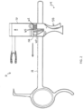
- FIG. 2 shows a side view of the drill guide 10 in the locked position.
- the trigger end 34 of the guide body 16 includes the trigger 58 with the aperture 60 configured to receive the guide rail 18 therethrough.
- the locking mechanism 62 is biased such that the trigger 58 is spaced from (or at least not actively engaged with) the spring 65 of the locking mechanism 62.
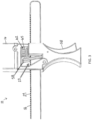
- the guide body 16 In the locked position ( FIGs. 2-3 ), the guide body 16 can slide distally along the guide rail 18. However, the guide body 16 cannot slide in the proximal direction. As shown in FIG. 3 , the plurality of ridges 22 extending along the surface 24 of the guide rail 18 prevent the trigger 58 (and consequently, the guide body 16) from moving in the proximal direction when the trigger 58 is in the locked position. As shown in FIG. 3 , in its relaxed, natural (locked) position, the trigger 58 catches on the ridges 22 when the guide body 16 is pulled/pushed in the proximal direction along the guide rail 18.
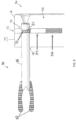
- FIG. 4 shows a side view of the proximal end 12 (with the cover plate 66 removed) of the drill guide 10 in the unlocked position.
- FIG. 5 shows a close-up perspective view of the arms 50 of the drill bullet 46.
- the pair of arms 50 can be connected to and extend from the shaft 48 of the drill bullet 46.
- the arms 50 are curved toward the central longitudinal y2-y2 axis in order to elevate the first metacarpal.
- the embodiment in FIG. 5 can also include a plurality of teeth 68 (or ridges) along an inner surface 70 of the arms 50. The base of the first metacarpal rests on the teeth 68 when the patient's hand is in the desired position within the drill guide 10.
- the arms 50 and the teeth 68 can be important for supporting and maintaining the position of the first metacarpal as the first metacarpal is typically loose in the joint after removal of the trapezium.
- a distal end 49 of the shaft 48 can also include a plurality of spaced, sharp tips 51 extending distally therefrom. The sharp tips 51 are used for additional support in maintaining the position of the first metacarpal.
- FIG. 6 shows a close-up side view of the locking mechanism 52 of the drilling end 36 of the guide body 16.
- a channel 72 extends through a surface 74 of the drilling end 36 and into the guide body 16.
- the spring 56 and the slug 54 are within the channel 72, with the slug 54 extending at least partially into the inner volume 40 of the drilling end 36 of the guide body 16.
- the slug 54 engages the shaft 48 of the drill bullet 46.
- a proximal end 76 of the shaft 48 comprises a plurality of grooves 78.
- the grooves 78 extend circumferentially around the shaft 48.
- a tip 80 of the slug 54 extends into one of the plurality of grooves 78 at a time.
- the spring 56 is biased to apply just enough force to maintain the tip 80 of the slug 54 in one of the plurality of grooves 78.
- the force applied by the spring 56 does not fully prevent rotation of the drill bullet 46 within the inner volume 40.
- the surgeon can rotate the drill bullet 46 so that the arms 50 are in a desired position at the base of the thumb.
- the drill bullet 46 is automatically maintained in the desired position as the tip 80 of the slug 54 moves into another of the plurality of grooves 78 as the drill bullet 46 rotates. This saves time because there is no step that the surgeon needs to accomplish before he or she can rotate the drill bullet 46 and no step to lock it in place after the desired position is reached.
- FIG. 7 there is shown a side view schematic representation of the drill guide 10 in the locked position, according to an embodiment.
- the drill guide 10 can be operated using one hand.
- the surgeon positions the sharp tip 32 of the spike 30 onto a desired drilling location on a second metacarpal (as should be understood by a person of ordinary skill in the art in conjunction with a review of this disclosure).
- the sharp tip 32 is positioned on the bone where the surgeon would like the drill with drill bit (not shown) to exit from.
- the surgeon squeezes his or her hand to bring the arms 50 of the drill bullet 46 tight against the base of the patient's thumb (assuming the base of the thumb is the desired start location for the drill tunnel). Then, by releasing pressure on the trigger 58, the drill guide 10 will automatically lock in position and maintain the pressure that the surgeon applied.
- FIG. 8 there is shown a side view schematic representation of the drill guide 10 in the unlocked position, according to an embodiment.
- the drill guide 10 is removed by first, pinching the trigger 58, and second, pulling the sliding guide body 16 in the proximal direction away from the bone. Thereafter, while still pinching the trigger 58, the guide body 16 can be pulled off the guide rail 18. With the guide body 16 removed, the guide rail 18 can be easily removed from its position on the patient's hand.
- Embodiments of the present disclosure are directed to each individual feature, system, article, material, kit, and/or method described herein.
- any combination of two or more such features, systems, articles, materials, kits, and/or methods, if such features, systems, articles, materials, kits, and/or methods are not mutually inconsistent, is included within the scope of the present disclosure.
- a method or device that "comprises”, “has”, “includes” or “contains” one or more steps or elements possesses those one or more features, but is not limited to possessing only those one or more features.
- a device or structure that is configured in a certain way is configured in at least that way, but may also be configured in ways that are not listed.
- the present invention is a drill guide.
- the drill guide includes a guide rail having an elongated shaft and a guide body with an aperture extending therethrough.
- the aperture is configured to receive the elongated shaft of the guide rail.
- the guide body of the drill guide also includes a trigger end.
- the trigger end has a locking mechanism that is movable between an unlocked position and a locked position. In the unlocked position, the guide body is slidable along the guide rail in a proximal direction.
- the guide body may only be slidable along the guide rail in a distal direction in the locked position.
- the device of the first aspect may further comprise a trigger attached to the trigger end of the guide body, the trigger having the aperture of the guide body extending therethrough.
- the device of the third aspect may further comprise a plurality of ridges on at least a portion of a surface of the guide rail.
- the trigger may catch at least one of the plurality of ridges when the guide body is pulled in the proximal direction, in the locked position.
- the locking mechanism may include a spring, which is compressed by the trigger in the unlocked position.
Landscapes
- Health & Medical Sciences (AREA)
- Life Sciences & Earth Sciences (AREA)
- Surgery (AREA)
- Orthopedic Medicine & Surgery (AREA)
- Medical Informatics (AREA)
- General Health & Medical Sciences (AREA)
- Biomedical Technology (AREA)
- Heart & Thoracic Surgery (AREA)
- Nuclear Medicine, Radiotherapy & Molecular Imaging (AREA)
- Molecular Biology (AREA)
- Animal Behavior & Ethology (AREA)
- Engineering & Computer Science (AREA)
- Public Health (AREA)
- Veterinary Medicine (AREA)
- Oral & Maxillofacial Surgery (AREA)
- Dentistry (AREA)
- Surgical Instruments (AREA)
- Pathology (AREA)
- Drilling And Exploitation, And Mining Machines And Methods (AREA)
Abstract
Description
- This application claims priority to
U.S. Provisional Patent Application Serial No. 62/744,686, filed on October 12, 2018 - The present invention is directed generally to a surgical system and, more particularly, to a drill guide to maintain particular positioning of bones in the thumb while maintaining the proper trajectory of a drill/drill bit.
- The carpometacarpal (CMC) joint is located at the base of the thumb and is responsible for providing a wide range of motion to the thumb. A CMC suspension is a procedure for repairing damage at the CMC joint. During the CMC suspension procedure, a surgeon will drill through the base of the first metacarpal and the proximal end of the second metacarpal. By using a drill guide, the surgeons can drill all the way through both the first and second metacarpals in one step. However, the first metacarpal is loose due to the removal of the trapezium before drilling, making the process of drilling at the desired location difficult. Further, when drilling in smaller bones, such as the first metacarpal, accuracy is critical.
- Therefore, there is a need for a device configured to control the first metacarpal while maintaining the proper trajectory of the drill/drill bit.
- Description of the Related Art Section Disclaimer: To the extent that specific patents/publications/products are discussed above in this Description of the Related Art Section or elsewhere in this disclosure, these discussions should not be taken as an admission that the discussed patents/publications/products are prior art for patent law purposes. For example, some or all of the discussed patents/publications/products may not be sufficiently early in time, may not reflect subject matter developed early enough in time and/or may not be sufficiently enabling so as to amount to prior art for patent law purposes. To the extent that specific patents/publications/products are discussed above in this Description of the Related Art Section and/or throughout the application, the descriptions/disclosures of which are all hereby incorporated by reference into this document in their respective entirety(ies).
- Embodiments of the present invention are directed to a drill guide for controlling the first metacarpal while maintaining the proper trajectory of a drill/drill bit.
- According to an embodiment, the drill guide includes a guide rail having an elongated shaft and a guide body with an aperture extending therethrough. The aperture is configured to receive the elongated shaft of the guide rail. The guide body also includes a drilling end with an aperture, creating an inner volume extending therethrough. The inner volume is configured to receive a drill bullet (which can be configured to fit a drill bit therein) therein. The drill bullet is rotatable within the inner volume of the drilling end of the guide body.
- According to another embodiment, the drill guide includes a guide rail having an elongated shaft extending along a first central longitudinal axis and a guide body with an aperture extending therethrough. The aperture is configured to receive the elongated shaft of the guide rail. The drill guide also includes a distal ring connected to the elongated shaft. A spike is attached to the distal ring and extends therefrom. A hook is also attached to the distal ring. The hook extends from the ring such that the hook and the spike extend from opposing positions along the distal ring.
- These and other aspects of the invention will be apparent from and elucidated with reference to the embodiment(s) described hereinafter.
- One or more aspects of the present invention are particularly pointed out and distinctly claimed as examples in the claims at the conclusion of the specification. The foregoing and other objects, features, and advantages of the invention are apparent from the following description taken in conjunction with the accompanying drawings in which:
-
FIG. 1 is an exploded perspective view schematic representation of a drill guide, according to an embodiment; -
FIG. 2 is a side view schematic representation of the drill guide in a locked position, according to an embodiment; -
FIG. 3 is a close-up side view schematic representation of the trigger in the locked position, according to an embodiment; -
FIG. 4 is a side view schematic representation of the proximal end of the drill guide in an unlocked position, according to an embodiment; -
FIG. 5 is a close-up perspective view schematic representation of the drill bullet of the drill guide, according to an embodiment; -
FIG. 6 is a close-up side view schematic representation of the drilling end of the guide body, according to an embodiment; -
FIG. 7 is a side view schematic representation of the drill guide in the locked position, according to an embodiment; and -
FIG. 8 is a side view schematic representation of the drill guide in the unlocked position, according to an embodiment. - Aspects of the present invention and certain features, advantages, and details thereof, are explained more fully below with reference to the non-limiting examples illustrated in the accompanying drawings. Descriptions of well-known structures are omitted so as not to unnecessarily obscure the invention in detail. It should be understood, however, that the detailed description and the specific non-limiting examples, while indicating aspects of the invention, are given by way of illustration only, and are not by way of limitation. Various substitutions, modifications, additions, and/or arrangements, within the spirit and/or scope of the underlying inventive concepts will be apparent to those skilled in the art from this disclosure.
- Referring now to the figures, wherein like reference numerals refer to like parts throughout,
FIG. 1 shows an exploded perspective view schematic representation of adrill guide 10, according to an embodiment. Thedrill guide 10 comprises aproximal end 12 and adistal end 14. At theproximal end 12, thedrill guide 10 includes aguide body 16. Theguide body 16 is configured to slide along aguide rail 18, which extends to thedistal end 14. - As shown in
FIG. 1 , theguide rail 18 has anelongated shaft 20 extending toward theproximal end 12 of thedrill guide 10. Theguide rail 18 extends along a central longitudinal y1-y1 axis. Theguide rail 18 comprises a plurality ofridges 22 extending along at least a portion of asurface 24 of theguide rail 18. Theguide rail 18 can have adistal ring 26 connected to theelongated shaft 20. Thedistal ring 26 has ahook 28 extending therefrom. In the depicted embodiment, thehook 28 is curved in the distal direction (but can curve in the proximal direction), extending substantially along a lateral x-x axis. In the depicted embodiment, thering 26 is substantially planar along the lateral x-x axis. - Still referring to
FIG. 1 , theguide rail 18 additionally includes aspike 30 extending from thering 26. In the depicted embodiment, thespike 30 extends substantially along the lateral x-x axis. As shown inFIG. 1 , thespike 30 extends from thering 26 in a direction opposing the hook 28 (but could extend in the same direction as the hook 28). In the depicted embodiment, the lateral x-x axis is substantially perpendicular to the central longitudinal y1-y1 axis.FIG. 1 also shows that thespike 30 includes asharp tip 32 extending in the proximal direction. - At the
proximal end 12 of thedrill guide 10, theguide body 16 includes a trigger end 34 and adrilling end 36. Thedrilling end 36 of theguide body 16 includes anaperture 38 defining aninner volume 40 extending from aproximal surface 42 of theguide body 16 to adistal surface 44 of theguide body 16. In the depicted embodiment, theinner volume 40 extends along a central longitudinal y2-y2 axis, which extending substantially parallel to the central longitudinal y1-y1 axis. In the depicted embodiment, thesharp tip 32 of thespike 30 also extends along the central longitudinal y2-y2 axis such that thesharp tip 32 is substantially aligned with theaperture 38 and/orinner volume 40 of thedrilling end 36 of theguide body 16. - The
inner volume 40 of thedrilling end 36 of theguide body 16 is configured to receive adrill bullet 46. Thedrill bullet 46 includes ashaft 48 extending proximally along the central longitudinal y2-y2 axis and a pair ofarms 50 extending distally from theshaft 48. Thedrilling end 36 of theguide body 16 can also include alocking mechanism 52 that maintains thedrill bullet 46 in the desired position. In the depicted embodiment, thelocking mechanism 52 includes a slug 54 (e.g., post) and aspring 56, as described in detail below. - Still referring to
FIG. 1 , the trigger end 34 of theguide body 16 includes atrigger 58 with anaperture 60 extending therethrough, which is configured to slidably receive theguide rail 18. Thetrigger 58 is connected to alocking mechanism 62 for locking the position of theguide body 16 along theguide rail 18. In the depicted embodiment, thelocking mechanism 62 includes aspring 65 that maintains pressure on thetrigger 58 and a trigger pin 64 that allows thetrigger 58 to toggle between an unlocked position and a locked position, as described in detail below. As shown, thelocking mechanism 62 is maintained within theguide body 16 with a cover plate 66. - Turning now to
FIGs. 2-4 , there are shown various views schematic representations of the trigger end 34 (with the cover plate 66 removed) of theguide body 16, according to an embodiment.FIG. 2 shows a side view of thedrill guide 10 in the locked position. As stated above, the trigger end 34 of theguide body 16 includes thetrigger 58 with theaperture 60 configured to receive theguide rail 18 therethrough. In the locked position, thelocking mechanism 62 is biased such that thetrigger 58 is spaced from (or at least not actively engaged with) thespring 65 of thelocking mechanism 62. - In the locked position (
FIGs. 2-3 ), theguide body 16 can slide distally along theguide rail 18. However, theguide body 16 cannot slide in the proximal direction. As shown inFIG. 3 , the plurality ofridges 22 extending along thesurface 24 of theguide rail 18 prevent the trigger 58 (and consequently, the guide body 16) from moving in the proximal direction when thetrigger 58 is in the locked position. As shown inFIG. 3 , in its relaxed, natural (locked) position, thetrigger 58 catches on theridges 22 when theguide body 16 is pulled/pushed in the proximal direction along theguide rail 18. -
FIG. 4 shows a side view of the proximal end 12 (with the cover plate 66 removed) of thedrill guide 10 in the unlocked position. To move the drill guide 10 from the locked position (FIGs. 2-3 ) to the unlocked position (FIG. 4 ), pressure is applied to thetrigger 58. When the surgeon squeezes thetrigger 58, thetrigger 58 is rotated away from the plurality ofridges 22 and against thespring 65 of thelocking mechanism 62. As thetrigger 58 is clear from theridges 22, theguide body 16 can be pulled/moved in the proximal direction without catching on theridges 22. Thus, in in the unlocked position, theguide body 16 can slide proximally and distally along theguide rail 18 and in the locked position, theguide body 16 can only slide distally along theguide rail 18. - Referring now to
FIGs. 5-6 , there are shown various views schematic representation of thedrilling end 36 of theguide body 16.FIG. 5 shows a close-up perspective view of thearms 50 of thedrill bullet 46. As stated above, the pair ofarms 50 can be connected to and extend from theshaft 48 of thedrill bullet 46. In the depicted embodiment, thearms 50 are curved toward the central longitudinal y2-y2 axis in order to elevate the first metacarpal. The embodiment inFIG. 5 can also include a plurality of teeth 68 (or ridges) along aninner surface 70 of thearms 50. The base of the first metacarpal rests on the teeth 68 when the patient's hand is in the desired position within thedrill guide 10. Thearms 50 and the teeth 68 can be important for supporting and maintaining the position of the first metacarpal as the first metacarpal is typically loose in the joint after removal of the trapezium. A distal end 49 of theshaft 48 can also include a plurality of spaced,sharp tips 51 extending distally therefrom. Thesharp tips 51 are used for additional support in maintaining the position of the first metacarpal. -
FIG. 6 shows a close-up side view of thelocking mechanism 52 of thedrilling end 36 of theguide body 16. As shown inFIG. 6 , achannel 72 extends through asurface 74 of thedrilling end 36 and into theguide body 16. Thespring 56 and theslug 54 are within thechannel 72, with theslug 54 extending at least partially into theinner volume 40 of thedrilling end 36 of theguide body 16. In theinner volume 40, theslug 54 engages theshaft 48 of thedrill bullet 46. Aproximal end 76 of theshaft 48 comprises a plurality ofgrooves 78. Thegrooves 78 extend circumferentially around theshaft 48. - Still referring to
FIG. 6 , atip 80 of theslug 54 extends into one of the plurality ofgrooves 78 at a time. Thespring 56 is biased to apply just enough force to maintain thetip 80 of theslug 54 in one of the plurality ofgrooves 78. The force applied by thespring 56 does not fully prevent rotation of thedrill bullet 46 within theinner volume 40. In use, the surgeon can rotate thedrill bullet 46 so that thearms 50 are in a desired position at the base of the thumb. Thedrill bullet 46 is automatically maintained in the desired position as thetip 80 of theslug 54 moves into another of the plurality ofgrooves 78 as thedrill bullet 46 rotates. This saves time because there is no step that the surgeon needs to accomplish before he or she can rotate thedrill bullet 46 and no step to lock it in place after the desired position is reached. - Referring now to
FIG. 7 , there is shown a side view schematic representation of thedrill guide 10 in the locked position, according to an embodiment. Thedrill guide 10 can be operated using one hand. The surgeon positions thesharp tip 32 of thespike 30 onto a desired drilling location on a second metacarpal (as should be understood by a person of ordinary skill in the art in conjunction with a review of this disclosure). Specifically, thesharp tip 32 is positioned on the bone where the surgeon would like the drill with drill bit (not shown) to exit from. Then, holding thedrill guide 10 with his or her fingers on thering 26 and thehook 28, and thumb on thetrigger 58, the surgeon squeezes his or her hand to bring thearms 50 of thedrill bullet 46 tight against the base of the patient's thumb (assuming the base of the thumb is the desired start location for the drill tunnel). Then, by releasing pressure on thetrigger 58, thedrill guide 10 will automatically lock in position and maintain the pressure that the surgeon applied. - Turning now to
FIG. 8 , there is shown a side view schematic representation of thedrill guide 10 in the unlocked position, according to an embodiment. After drilling the tunnel through the first and second metacarpals, thedrill guide 10 is removed by first, pinching thetrigger 58, and second, pulling the slidingguide body 16 in the proximal direction away from the bone. Thereafter, while still pinching thetrigger 58, theguide body 16 can be pulled off theguide rail 18. With theguide body 16 removed, theguide rail 18 can be easily removed from its position on the patient's hand. - All definitions, as defined and used herein, should be understood to control over dictionary definitions, definitions in documents incorporated by reference, and/or ordinary meanings of the defined terms.
- While various embodiments have been described and illustrated herein, those of ordinary skill in the art will readily envision a variety of other means and/or structures for performing the function and/or obtaining the results and/or one or more of the advantages described herein, and each of such variations and/or modifications is deemed to be within the scope of the embodiments described herein. More generally, those skilled in the art will readily appreciate that all parameters, dimensions, materials, and configurations described herein are meant to be exemplary and that the actual parameters, dimensions, materials, and/or configurations will depend upon the specific application or applications for which the teachings is/are used. Those skilled in the art will recognize, or be able to ascertain using no more than routine experimentation, many equivalents to the specific embodiments described herein. Embodiments of the present disclosure are directed to each individual feature, system, article, material, kit, and/or method described herein. In addition, any combination of two or more such features, systems, articles, materials, kits, and/or methods, if such features, systems, articles, materials, kits, and/or methods are not mutually inconsistent, is included within the scope of the present disclosure.
- The terminology used herein is for the purpose of describing particular embodiments only and is not intended to be limiting of the invention. As used herein, the singular forms "a", "an" and "the" are intended to include the plural forms as well, unless the context clearly indicates otherwise. It will be further understood that the terms "comprise" (and any form of comprise, such as "comprises" and "comprising"), "have" (and any form of have, such as, "has" and "having"), "include" (and any form of include, such as "includes" and "including"), and "contain" (any form of contain, such as "contains" and "containing") are open-ended linking verbs. As a result, a method or device that "comprises", "has", "includes" or "contains" one or more steps or elements. Likewise, a step of method or an element of a device that "comprises", "has", "includes" or "contains" one or more features possesses those one or more features, but is not limited to possessing only those one or more features. Furthermore, a device or structure that is configured in a certain way is configured in at least that way, but may also be configured in ways that are not listed.
- The embodiment was chosen and described in order to best explain the principles of one or more aspects of the invention and the practical application, and to enable others of ordinary skill in the art to understand one or more aspects of the present invention for various embodiments with various modifications as are suited to the particular use contemplated.
- The present invention further embraces the following aspects. According to a first aspect, the present invention is a drill guide. The drill guide includes a guide rail having an elongated shaft and a guide body with an aperture extending therethrough. The aperture is configured to receive the elongated shaft of the guide rail. The guide body of the drill guide also includes a trigger end. The trigger end has a locking mechanism that is movable between an unlocked position and a locked position. In the unlocked position, the guide body is slidable along the guide rail in a proximal direction.
- According to a second aspect, in the device of the first aspect, the guide body may only be slidable along the guide rail in a distal direction in the locked position.
- According to a third aspect, the device of the first aspect may further comprise a trigger attached to the trigger end of the guide body, the trigger having the aperture of the guide body extending therethrough. According to a fourth aspect, the device of the third aspect may further comprise a plurality of ridges on at least a portion of a surface of the guide rail. According to a fifth aspect, in the device of the fourth aspect, the trigger may catch at least one of the plurality of ridges when the guide body is pulled in the proximal direction, in the locked position.
- According to a sixth aspect, in the device of the fifth aspect, the locking mechanism may include a spring, which is compressed by the trigger in the unlocked position.
Claims (14)
- A drill guide, comprising:a guide rail (18) having an elongated shaft (20);a guide body (16) with an aperture (60) extending therethrough, the aperture configured to receive the elongated shaft of the guide rail;a drilling end (36) of the guide body with an aperture (38), creating an inner volume (40) extending therethrough, the inner volume configured to receive a drill bullet (46) therein; andwherein the drill bullet is rotatable within the inner volume of the drilling end of the guide body.
- The drill guide of claim 1, further comprising a plurality of grooves (78) extending circumferentially around the drill bullet (46).
- The drill guide of claim 2, further comprising a locking mechanism (52) within the drilling end (36) of the guide body (16) configured to stop rotation of the drill bullet (46).
- The drill guide of claim 3, wherein the locking mechanism (52) includes a slug (54) biased by a spring (56) such that at least a portion of the slug is within one of the plurality of grooves (78).
- The drill guide of claim 1, wherein the drill bullet (46) comprises a shaft (48) connected to a pair of arms (50) extending in a distal direction.
- The drill guide of claim 5, further comprising a plurality of teeth (68) along an inner surface of at least one of the arms (50).
- The drill guide of claim 1, wherein a distal end of the drill bullet (46) comprises a plurality of spaced, sharp tips (51) extending in a distal direction.
- A drill guide, comprising:a guide rail (18) having an elongated shaft (20) extending along a first central longitudinal axis;a guide body (16) with an aperture (60) extending therethrough, the aperture configured to receive the elongated shaft of the guide rail;a distal ring (26) connected to the elongated shaft;a spike (30) attached to the distal ring and extending therefrom; anda hook (28) attached to the distal ring and extending therefrom such that the hook and the spike extend from opposing positions along the distal ring.
- The drill guide of claim 8, wherein the spike (30) extends along a central lateral axis and the first central longitudinal axis is substantially perpendicular to the central lateral axis.
- The drill guide of claim 8, further comprising a sharp tip (32) extending proximally from the spike (30).
- The drill guide of claim 10, wherein the sharp tip (32) extends along a second central longitudinal axis which is substantially parallel to the first central longitudinal axis.
- The drill guide of claim 9, wherein the ring (26) is substantially planar with the central lateral axis.
- The drill guide of claim 8, further comprising a trigger end (34) of the guide body (16) having a trigger (58), wherein the trigger, when actuated, allows the guide body to slide along the guide rail (18) in a proximal direction.
- The drill guide of claim 8, further comprising a drilling end (36) of the guide body (16) having a rotatable drill bullet (46) extending distally therefrom, wherein the drill bullet is substantially aligned with the sharp tip (32) of the spike (30).
Applications Claiming Priority (3)
| Application Number | Priority Date | Filing Date | Title |
|---|---|---|---|
| US201862744686P | 2018-10-12 | 2018-10-12 | |
| EP19734595.2A EP3863531B1 (en) | 2018-10-12 | 2019-06-12 | Drill guide assembly |
| PCT/US2019/036660 WO2020076376A1 (en) | 2018-10-12 | 2019-06-12 | Drill guide assembly |
Related Parent Applications (2)
| Application Number | Title | Priority Date | Filing Date |
|---|---|---|---|
| EP19734595.2A Division-Into EP3863531B1 (en) | 2018-10-12 | 2019-06-12 | Drill guide assembly |
| EP19734595.2A Division EP3863531B1 (en) | 2018-10-12 | 2019-06-12 | Drill guide assembly |
Publications (2)
| Publication Number | Publication Date |
|---|---|
| EP4501246A2 true EP4501246A2 (en) | 2025-02-05 |
| EP4501246A3 EP4501246A3 (en) | 2025-07-23 |
Family
ID=67108178
Family Applications (2)
| Application Number | Title | Priority Date | Filing Date |
|---|---|---|---|
| EP19734595.2A Active EP3863531B1 (en) | 2018-10-12 | 2019-06-12 | Drill guide assembly |
| EP24218986.8A Pending EP4501246A3 (en) | 2018-10-12 | 2019-06-12 | Drill guide assembly |
Family Applications Before (1)
| Application Number | Title | Priority Date | Filing Date |
|---|---|---|---|
| EP19734595.2A Active EP3863531B1 (en) | 2018-10-12 | 2019-06-12 | Drill guide assembly |
Country Status (9)
| Country | Link |
|---|---|
| US (2) | US12364490B2 (en) |
| EP (2) | EP3863531B1 (en) |
| JP (3) | JP7344284B2 (en) |
| KR (3) | KR102581187B1 (en) |
| CN (1) | CN112912020A (en) |
| AU (2) | AU2019356439B2 (en) |
| CA (1) | CA3113181A1 (en) |
| ES (1) | ES3016984T3 (en) |
| WO (1) | WO2020076376A1 (en) |
Families Citing this family (1)
| Publication number | Priority date | Publication date | Assignee | Title |
|---|---|---|---|---|
| EP4292571B1 (en) * | 2020-10-30 | 2026-04-29 | Waldemar Link GmbH & Co. KG | Retainer for an interphalangeal implant |
Family Cites Families (46)
| Publication number | Priority date | Publication date | Assignee | Title |
|---|---|---|---|---|
| US4739751A (en) * | 1986-10-03 | 1988-04-26 | Temple University | Apparatus and method for reconstructive surgery |
| US5234434A (en) * | 1992-08-17 | 1993-08-10 | Marlowe Goble E | Mutliple guide sleeve drill guide |
| US5312412A (en) * | 1993-02-03 | 1994-05-17 | Whipple Terry L | Fixation alignment guide for surgical use |
| US5613971A (en) * | 1995-08-11 | 1997-03-25 | Depuy Inc. | Ratcheting tibial and femoral guide |
| US6120511A (en) * | 1997-11-18 | 2000-09-19 | Chan; Kwan-Ho | Drill guide assembly and method for producing a bone tunnel |
| US5968050A (en) * | 1997-12-05 | 1999-10-19 | Smith & Nephew, Inc. | Positioning a tibial tunnel |
| US6342056B1 (en) | 2000-02-04 | 2002-01-29 | Jean-Marc Mac-Thiong | Surgical drill guide and method for using the same |
| US6210415B1 (en) | 2000-02-18 | 2001-04-03 | Lab Engineering & Manufacturing, Inc. | Surgical drill guide |
| JP2002102236A (en) | 2000-10-02 | 2002-04-09 | Koseki Ika Kk | Drill guide for patella |
| US6524238B2 (en) | 2000-12-20 | 2003-02-25 | Synthes Usa | Universal handle and method for use |
| FR2823093B1 (en) | 2001-04-04 | 2003-12-19 | Newdeal Sa | GUIDE FOR ANGULAR POSITIONING OF THE BONES OF A JOINT WITH A VIEW TO ACHIEVING AN ARTHRODESIS |
| US6679888B2 (en) | 2001-05-29 | 2004-01-20 | Synthes | Femur lever |
| JP2007501063A (en) * | 2003-08-01 | 2007-01-25 | ジンテス ゲゼルシャフト ミット ベシュレンクテル ハフツング | Drill guide assembly for bone fixation device |
| US7357804B2 (en) * | 2003-08-13 | 2008-04-15 | Synthes (U.S.A.) | Quick-release drill-guide assembly for bone-plate |
| GB0322084D0 (en) | 2003-09-22 | 2003-10-22 | Depuy Int Ltd | A drill guide assembly |
| EP1588668B1 (en) | 2004-04-20 | 2008-12-10 | Finsbury (Development) Limited | Alignment guide for use in femoral head surgery |
| US20060195116A1 (en) | 2005-02-25 | 2006-08-31 | Fox Michael D | D-Tail patellar bone tunneling system |
| US20060195108A1 (en) | 2005-02-25 | 2006-08-31 | Fox Michael D | Patellar bone tunneling system |
| GB0525637D0 (en) * | 2005-12-16 | 2006-01-25 | Finsbury Dev Ltd | Tool |
| GB0607958D0 (en) | 2006-04-21 | 2006-05-31 | Imp College Innovations Ltd | Tendon repair |
| US7815646B2 (en) * | 2007-06-06 | 2010-10-19 | Karl Storz Gmbh & Co. Kg | Drill guide and method for placing a fixation device hole |
| US9826992B2 (en) | 2007-12-21 | 2017-11-28 | Smith & Nephew, Inc. | Multiple portal guide |
| EP2231035B1 (en) | 2007-12-21 | 2019-08-07 | Smith & Nephew, Inc. | Multiple portal guide |
| WO2009155111A1 (en) | 2008-05-30 | 2009-12-23 | Wright Medical Technology, Inc. | Drill guide assembly |
| US8277459B2 (en) | 2009-09-25 | 2012-10-02 | Tarsus Medical Inc. | Methods and devices for treating a structural bone and joint deformity |
| US8617168B2 (en) | 2010-10-25 | 2013-12-31 | Smith & Nephew, Inc. | Oval tibia guide |
| WO2012061639A1 (en) | 2010-11-03 | 2012-05-10 | Smith & Nephew, Inc. | Drill guide |
| WO2012061733A1 (en) | 2010-11-04 | 2012-05-10 | Smith & Nephew, Inc. | Drill guide depth stop |
| US8403939B2 (en) | 2010-11-05 | 2013-03-26 | Biomet, C.V. | Surgical drill guide |
| MX348238B (en) | 2011-03-09 | 2017-05-29 | Smith & Nephew Inc | Multiple portal guide. |
| JP2014531936A (en) | 2011-09-30 | 2014-12-04 | ザ・トラスティーズ・オブ・コロンビア・ユニバーシティ・イン・ザ・シティ・オブ・ニューヨーク | Systems and devices for bone reduction and articulation |
| CA2904652C (en) * | 2013-03-14 | 2021-11-02 | Wright Medical Technology, Inc. | Ankle replacement system and method |
| US20140277450A1 (en) | 2013-03-14 | 2014-09-18 | Mark J. Warburton | Apparatus and methods for aol and drl reconstruction of cmc joints |
| JP5802730B2 (en) * | 2013-11-22 | 2015-11-04 | タキロン株式会社 | Guide pin piercing jig |
| US10123813B2 (en) * | 2014-02-17 | 2018-11-13 | Smith & Nephew, Inc. | Drill guide |
| US10179001B2 (en) * | 2014-06-30 | 2019-01-15 | DePuy Synthes Products, Inc. | Bone reduction forceps and plate holding forceps |
| US20160256177A1 (en) | 2014-08-14 | 2016-09-08 | Carlos A. Alvarado | 3-d femur orthopedic drill guide |
| AU2014405942B2 (en) | 2014-09-12 | 2019-05-16 | Innovision, Inc. | Bone drill guides and methods of use thereof |
| US10045789B2 (en) | 2014-09-30 | 2018-08-14 | Medos International Sàrl | Universal surgical guide systems and methods |
| US10010333B2 (en) * | 2014-09-30 | 2018-07-03 | Medos International Sàrl | Side-loading carriage for use in surgical guide |
| US10357314B2 (en) * | 2015-07-08 | 2019-07-23 | Stryker European Holdings I, Llc | Instrumentation and method for repair of a bone fracture |
| US9622805B2 (en) * | 2015-08-14 | 2017-04-18 | Treace Medical Concepts, Inc. | Bone positioning and preparing guide systems and methods |
| CN108348344B (en) | 2015-09-14 | 2020-08-07 | 莱迪科矫形外科公司 | Methods, devices and implants for scapholunate reconstruction |
| US10357260B2 (en) * | 2015-11-02 | 2019-07-23 | First Ray, LLC | Orthopedic fastener, retainer, and guide methods |
| US11020132B2 (en) * | 2016-04-24 | 2021-06-01 | T.A.G. Medical Devices—Agriculture Cooperative Ltd. | Guiding device and method of using thereof |
| US10441317B2 (en) * | 2016-10-26 | 2019-10-15 | SIGN Fracture Care International | Bone fixation system and method using a clamping instrument to guide fastener placement |
-
2019
- 2019-06-12 CA CA3113181A patent/CA3113181A1/en active Pending
- 2019-06-12 AU AU2019356439A patent/AU2019356439B2/en active Active
- 2019-06-12 US US17/284,502 patent/US12364490B2/en active Active
- 2019-06-12 EP EP19734595.2A patent/EP3863531B1/en active Active
- 2019-06-12 KR KR1020217012336A patent/KR102581187B1/en active Active
- 2019-06-12 JP JP2021519585A patent/JP7344284B2/en active Active
- 2019-06-12 ES ES19734595T patent/ES3016984T3/en active Active
- 2019-06-12 KR KR1020237031567A patent/KR102720986B1/en active Active
- 2019-06-12 KR KR1020247034811A patent/KR102834592B1/en active Active
- 2019-06-12 WO PCT/US2019/036660 patent/WO2020076376A1/en not_active Ceased
- 2019-06-12 EP EP24218986.8A patent/EP4501246A3/en active Pending
- 2019-06-12 CN CN201980067281.3A patent/CN112912020A/en active Pending
-
2022
- 2022-07-13 AU AU2022205206A patent/AU2022205206B2/en active Active
-
2023
- 2023-03-23 JP JP2023046122A patent/JP7682940B2/en active Active
-
2025
- 2025-05-14 JP JP2025080877A patent/JP2025114805A/en active Pending
- 2025-07-21 US US19/275,586 patent/US20250345075A1/en active Pending
Also Published As
| Publication number | Publication date |
|---|---|
| CN112912020A (en) | 2021-06-04 |
| EP3863531A1 (en) | 2021-08-18 |
| US12364490B2 (en) | 2025-07-22 |
| KR20210069066A (en) | 2021-06-10 |
| JP2022502208A (en) | 2022-01-11 |
| EP3863531B1 (en) | 2025-01-15 |
| AU2022205206A1 (en) | 2022-08-04 |
| US20250345075A1 (en) | 2025-11-13 |
| JP2025114805A (en) | 2025-08-05 |
| JP2023078377A (en) | 2023-06-06 |
| JP7344284B2 (en) | 2023-09-13 |
| JP7682940B2 (en) | 2025-05-26 |
| AU2019356439A1 (en) | 2021-04-15 |
| AU2019356439B2 (en) | 2022-04-14 |
| CA3113181A1 (en) | 2020-04-16 |
| KR102581187B1 (en) | 2023-09-20 |
| US20210386438A1 (en) | 2021-12-16 |
| KR102720986B1 (en) | 2024-10-22 |
| KR102834592B1 (en) | 2025-07-16 |
| ES3016984T3 (en) | 2025-05-12 |
| WO2020076376A1 (en) | 2020-04-16 |
| KR20240154701A (en) | 2024-10-25 |
| AU2022205206B2 (en) | 2024-08-29 |
| EP4501246A3 (en) | 2025-07-23 |
| KR20230136685A (en) | 2023-09-26 |
Similar Documents
| Publication | Publication Date | Title |
|---|---|---|
| US20210283379A1 (en) | Catheter Insertion Device Including Retractable Needle | |
| US12558121B2 (en) | Expanders for rod retraction | |
| KR102345946B1 (en) | Apparatus and method for tissue retraction | |
| CN105769272A (en) | Biceps tenodesis delivery tools | |
| US20250345075A1 (en) | Drill guide assembly | |
| EP3028653A1 (en) | Laparoscopic surgical ligation clip applier | |
| CN109414278B (en) | Access device with anchoring features and method of use thereof | |
| CN109247981B (en) | Retrieval instrument suitable for removing the distal portion of a bone implant from bone tissue | |
| US10820934B2 (en) | Surgical guidewire centering device | |
| EP2967537B1 (en) | Apparatus facilitating the repositioning of implanted medical devices | |
| CA2103389C (en) | Device for implanting an endoprosthesis | |
| US9968374B2 (en) | Method and instruments for placement of flexible cannulae | |
| EP4238505A2 (en) | Removable, adjustable-length, snap-in portal saver, decoupled from dermal fixation |
Legal Events
| Date | Code | Title | Description |
|---|---|---|---|
| PUAI | Public reference made under article 153(3) epc to a published international application that has entered the european phase |
Free format text: ORIGINAL CODE: 0009012 |
|
| STAA | Information on the status of an ep patent application or granted ep patent |
Free format text: STATUS: REQUEST FOR EXAMINATION WAS MADE |
|
| 17P | Request for examination filed |
Effective date: 20241211 |
|
| AC | Divisional application: reference to earlier application |
Ref document number: 3863531 Country of ref document: EP Kind code of ref document: P |
|
| AK | Designated contracting states |
Kind code of ref document: A2 Designated state(s): AL AT BE BG CH CY CZ DE DK EE ES FI FR GB GR HR HU IE IS IT LI LT LU LV MC MK MT NL NO PL PT RO RS SE SI SK SM TR |
|
| REG | Reference to a national code |
Ref country code: DE Ref legal event code: R079 Free format text: PREVIOUS MAIN CLASS: A61B0017000000 Ipc: A61B0017170000 |
|
| PUAL | Search report despatched |
Free format text: ORIGINAL CODE: 0009013 |
|
| AK | Designated contracting states |
Kind code of ref document: A3 Designated state(s): AL AT BE BG CH CY CZ DE DK EE ES FI FR GB GR HR HU IE IS IT LI LT LU LV MC MK MT NL NO PL PT RO RS SE SI SK SM TR |
|
| RIC1 | Information provided on ipc code assigned before grant |
Ipc: A61B 17/17 20060101AFI20250616BHEP Ipc: A61B 17/88 20060101ALI20250616BHEP Ipc: A61B 17/00 20060101ALI20250616BHEP |
|
| STAA | Information on the status of an ep patent application or granted ep patent |
Free format text: STATUS: EXAMINATION IS IN PROGRESS |