EP4501198A1 - Cup washer - Google Patents
Cup washer Download PDFInfo
- Publication number
- EP4501198A1 EP4501198A1 EP23872900.8A EP23872900A EP4501198A1 EP 4501198 A1 EP4501198 A1 EP 4501198A1 EP 23872900 A EP23872900 A EP 23872900A EP 4501198 A1 EP4501198 A1 EP 4501198A1
- Authority
- EP
- European Patent Office
- Prior art keywords
- detergent
- rinse
- tub
- water
- cup
- Prior art date
- Legal status (The legal status is an assumption and is not a legal conclusion. Google has not performed a legal analysis and makes no representation as to the accuracy of the status listed.)
- Pending
Links
Images







Classifications
-
- A—HUMAN NECESSITIES
- A47—FURNITURE; DOMESTIC ARTICLES OR APPLIANCES; COFFEE MILLS; SPICE MILLS; SUCTION CLEANERS IN GENERAL
- A47L—DOMESTIC WASHING OR CLEANING; SUCTION CLEANERS IN GENERAL
- A47L15/00—Washing or rinsing machines for crockery or tableware
- A47L15/0065—Washing or rinsing machines for crockery or tableware specially adapted for drinking glasses
-
- A—HUMAN NECESSITIES
- A47—FURNITURE; DOMESTIC ARTICLES OR APPLIANCES; COFFEE MILLS; SPICE MILLS; SUCTION CLEANERS IN GENERAL
- A47L—DOMESTIC WASHING OR CLEANING; SUCTION CLEANERS IN GENERAL
- A47L15/00—Washing or rinsing machines for crockery or tableware
- A47L15/42—Details
- A47L15/4246—Details of the tub
-
- A—HUMAN NECESSITIES
- A47—FURNITURE; DOMESTIC ARTICLES OR APPLIANCES; COFFEE MILLS; SPICE MILLS; SUCTION CLEANERS IN GENERAL
- A47L—DOMESTIC WASHING OR CLEANING; SUCTION CLEANERS IN GENERAL
- A47L15/00—Washing or rinsing machines for crockery or tableware
- A47L15/42—Details
- A47L15/44—Devices for adding cleaning agents; Devices for dispensing cleaning agents, rinsing aids or deodorants
- A47L15/4418—Devices for adding cleaning agents; Devices for dispensing cleaning agents, rinsing aids or deodorants in the form of liquids
-
- A—HUMAN NECESSITIES
- A47—FURNITURE; DOMESTIC ARTICLES OR APPLIANCES; COFFEE MILLS; SPICE MILLS; SUCTION CLEANERS IN GENERAL
- A47L—DOMESTIC WASHING OR CLEANING; SUCTION CLEANERS IN GENERAL
- A47L15/00—Washing or rinsing machines for crockery or tableware
- A47L15/42—Details
- A47L15/4214—Water supply, recirculation or discharge arrangements; Devices therefor
- A47L15/4225—Arrangements or adaption of recirculation or discharge pumps
-
- A—HUMAN NECESSITIES
- A47—FURNITURE; DOMESTIC ARTICLES OR APPLIANCES; COFFEE MILLS; SPICE MILLS; SUCTION CLEANERS IN GENERAL
- A47L—DOMESTIC WASHING OR CLEANING; SUCTION CLEANERS IN GENERAL
- A47L15/00—Washing or rinsing machines for crockery or tableware
- A47L15/42—Details
- A47L15/44—Devices for adding cleaning agents; Devices for dispensing cleaning agents, rinsing aids or deodorants
- A47L15/4418—Devices for adding cleaning agents; Devices for dispensing cleaning agents, rinsing aids or deodorants in the form of liquids
- A47L15/4427—Devices for adding cleaning agents; Devices for dispensing cleaning agents, rinsing aids or deodorants in the form of liquids entrained in the water supply line by a pressure drop, e.g. resulting from a Venturi throat
-
- A—HUMAN NECESSITIES
- A47—FURNITURE; DOMESTIC ARTICLES OR APPLIANCES; COFFEE MILLS; SPICE MILLS; SUCTION CLEANERS IN GENERAL
- A47L—DOMESTIC WASHING OR CLEANING; SUCTION CLEANERS IN GENERAL
- A47L15/00—Washing or rinsing machines for crockery or tableware
- A47L15/42—Details
- A47L15/48—Drying arrangements
- A47L15/486—Blower arrangements
Definitions
- the present disclosure relates to a cup washer, and more specifically, to a cup washer for washing a cup carried by a user.
- the cup washer capable of cleaning the cup carried by the user is placed in the store such that the user cleans his or her cup in the store using the cup washer to provide the convenience.
- the cup washer needs to have a structure such that the cup washer may be easily used by anyone.
- the related art related to a cup washer is disclosed in Korean Patent Application Laid-Open No. 10-020-0016470 .
- a cup washing process may largely include a washing step of spraying water to the cup to wash the cup, and then, a rinsing step of spraying clean water to the cup again to rinse the cup.
- the washing step may be performed using a mixture of detergent with water, and the rinsing step may be performed using a mixture of a rinse with water.
- the detergent injection device and the rinse injection device need to be configured such that the detergent and the rinse are injected into the washing unit at an appropriate time as the washing process proceeds without the user manually operating the detergent injection device and the rinse injection device.
- the detergent is a material used to wash foreign substances remaining in the cup
- the rinse is a material used to rinse the detergent remaining in the cup after finishing the cup washing using the detergent.
- the detergent injection device and the rinse injection device need to be configured so that a path along which the detergent is injected into the washing unit and a path along which the rinse is injected into the washing unit are separated from each other.
- a purpose of the present disclosure is to provide a cup washer having a device for injecting a detergent into a washing unit and a device for injecting a rinse into the washing unit.
- Another purpose of the present disclosure is to provide a cup washer having a detergent injection device and a rinse injection device which automatically operate without the user separately operating the detergent injection device and the rinse injection device.
- Still another purpose of the present disclosure is to provide a cup washer having a detergent injection device and a rinse injection device in which a path through which detergent is injected to a tub and a path through which rinse is injected into the tub are separated from each other.
- Still yet another purpose of the present disclosure is to provide a cup washer having a structure in which water introduced into washing water is effectively mixed with detergent or rinse.
- An embodiment of the cup washer may include a washing unit for washing a cup accommodated therein.
- the washing unit may include: a detergent storage disposed on one side of the tub and storing detergent therein; a detergent injection part coupled to a bottom of the detergent storage; a detergent pump connected to the detergent injection part for pumping the detergent to the tub; a rinse storage separated from the detergent storage and disposed on one side of the tub for storing the rinse therein; a rinse injection part coupled to a bottom of the rinse storage; and a rinse pump connected to the rinse injection part for pumping the rinse to the tub.
- Each of the detergent pump and the rinse pump may be connected to a controller provided in the cup washer and may operate at a time set by the controller to inject each of the detergent and the rinse to the tub so as to be mixed with water in the tub.
- An embodiment of the cup washer may include: a first connection pipe connecting a washing water inlet and the water storage tank to each other; a second connection pipe connecting the rinse injection nozzle and the first connection pipe to each other; and a three-way fitting fitted with the first connection pipe and fitted with one end of the second connection pipe.
- the rinse may be introduced into the tub through the second connection pipe, the three-way fitting, the first connection pipe, and the washing water inlet.
- the detergent may be introduced into the tub through a detergent inlet connected to a separate pipe.
- the rinse discharged from the rinse injection nozzle may be introduced into the first connection pipe from the second connection pipe and may be mixed with water flowing through the first connection pipe and then the mixture may be introduced into the tub. Accordingly, the water and the rinse may meet each other in one pipe to form the mixture which in turn may flow into the tub through the detergent inlet.
- the washing unit may include a rack.
- the rack may be provided inside the tub, and the cup may be seated on the rack.
- a plurality of wires may be coupled to each other to form the rack.
- the rack may include a first flow path guide.
- the first flow path guide may be coupled to a bottom portion and oriented to face the washing water inlet, so that the water introduced from the washing water inlet may be directed toward the detergent flowing into the detergent inlet.
- the first flow path guide may be disposed in a rear portion of an inner space of the tub and disposed at a position adjacent to the washing water inlet. Accordingly, the water introduced into the washing water inlet and poured into the tub may collide with the first flow path guide such that a flow direction of the water may be changed.
- the washing unit of the cup washer may include a tub having a cup receiving space defined therein, wherein washing water is sprayed into the tub; a detergent storage disposed on one side of the tub and configured to store therein detergent; a detergent injection part coupled to a bottom of the detergent storage; and a detergent pump connected to the detergent injection part and configured to pump the detergent to the tub.
- the detergent pump may include: a first connector connected to the detergent injection part and configured to receive the detergent from the detergent injection part; and a detergent discharge part having one side connected to the first connector and configured to discharge the detergent into the tub.
- the detergent discharge part may include: a detergent pumping part connected to the first connector and configured to receive the detergent from the first connector and pump the received detergent; and a detergent injection nozzle coupled to the detergent pumping part, and connected to the tub, and configured to inject the detergent into the tub.
- the washing unit may further include: a rinse storage disposed on one side of the tub and spaced from the detergent storage and configured to store therein rinse; a rinse injection part coupled to a bottom of the rinse storage; and a rinse pump connected to the rinse injection part and configured to pump the rinse to the tub.
- the rinse pump may include: a second connector connected to the rinse injection part and configured to receive the rinse from the rinse injection part; and a rinse discharge part having one side connected to the second connector and the other side connected to the tub, and configured to discharge the rinse into the tub.
- the rinse discharge part may include: a rinse pumping part connected to the second connector and configured to receive the rinse from the second connector and pump the received rinse; and a rinse injection nozzle coupled to the rinse pumping part, and connected to the tub, and configured to inject the rinse into the tub.
- the detergent injection part may further include: a first lower cover coupled to the bottom of the detergent storage; and a first connection portion protruding downwardly from the first lower cover, and coupled to the first connector, and having a first flow hole defined therein through which the detergent flows, wherein the first lower cover has an upper surface extending in a downwardly inclined manner as the upper surface extends toward the first flow hole.
- the rinse injection part may further include: a second lower cover coupled to the bottom of the rinse storage; and a second connection portion protruding downwardly from the second lower cover, and coupled to the second connector, and having a second flow hole defined therein through which the rinse flows, wherein the second lower cover has an upper surface extending in a downwardly inclined manner as the upper surface extends toward the second flow hole.
- the tub may include: a detergent inlet connected to the detergent injection nozzle through a pipe so as to receive the detergent from the detergent injection nozzle; and a washing water inlet disposed on top of the detergent inlet, wherein water flows into the tub through the washing water inlet.
- the cup washer may further include a water storage tank disposed under the washing unit and configured to store therein water; a first connection pipe connecting the washing water inlet and the water storage tank to each other; a second connection pipe connecting the rinse injection nozzle and the first connection pipe to each other; and a three-way fitting fitted with the first connection pipe, wherein one end of the second connection pipe is fitted with the three-way fitting.
- the rinse discharged from the rinse injection nozzle flows from the second connection pipe into the first connection pipe and is mixed with water flowing through the first connection pipe, and then, a mixture of the rinse and the water is introduced into the tub.
- the washing unit may further include: a drying module disposed on a side surface of the tub and configured to spray heated air into the tub; a sump disposed under the tub and configured to store therein water sprayed from the tub; a circulation pump disposed under the tub and configured to circulate water between the tub and the sump; and a water discharging pump disposed under the tub and configured to discharge water from the sump to an outside.
- a drying module disposed on a side surface of the tub and configured to spray heated air into the tub
- a sump disposed under the tub and configured to store therein water sprayed from the tub
- a circulation pump disposed under the tub and configured to circulate water between the tub and the sump
- a water discharging pump disposed under the tub and configured to discharge water from the sump to an outside.
- the detergent injection part may further include: a (1-1)-st cover coupling protrusion protruding from the first lower cover and coupled to the tub; a (1-2)-nd cover coupling protrusion protruding from the first lower cover and coupled to the first connector; and a (1-3)-rd cover coupling protrusion protruding from the first lower cover and having a first hook-receiving groove defined therein.
- the first connector may include: a first fastening portion fastened to the (1-2)-nd cover coupling protrusion; and a first coupling hook inserted into the first hook-receiving groove so as to be coupled to the (1-3)-rd cover coupling protrusion.
- the detergent pump may include a first body to which the first connector is coupled, wherein the first body may include a (1-1)-st module fastening portion formed to protrude in a lateral direction and fastened to the drying module, wherein the drying module may include a (1-2)-nd module fastening portion protruding toward the (1-1)-st module fastening portion, wherein the (1-1)-st module fastening portion is fastened to the (1-2)-nd module fastening portion.
- the rinse injection part may further include: a (2-1)-st cover coupling protrusion protruding from the second lower cover and coupled to the tub; a (2-2)-nd cover coupling protrusion protruding from the second lower cover and coupled to the second connector; and a (2-3)-rd cover coupling protrusion protruding from the second lower cover and having a second hook-receiving groove defined therein.
- the second connector may include: a second fastening portion fastened to the (2-2)-nd cover coupling protrusion; and a second coupling hook inserted into the second hook-receiving groove so as to be coupled to the (2-3)-rd cover coupling protrusion.
- the rinse pump may include a second body to which the second connector is coupled, wherein the second body may include a (2-1)-st module fastening portion formed to protrude in a lateral direction and fastened to the drying module, wherein the drying module may include a (2-2)-nd module fastening portion protruding toward the (2-1)-st module fastening portion, wherein the (2-1)-st module fastening portion is fastened to the (2-2)-nd module fastening portion.
- the detergent injection device and the rinse injection device may be disposed outside the tub to and may be separated from each other.
- the water introduced into the tub may be mixed with the detergent and the rinse via the detergent injection device and the rinse injection device, respectively.
- the washing water as a mixture of water and the detergent may be sprayed to the cup to increase the washing efficiency of the cup.
- the washing water as a mixture of water and the rinse may be sprayed onto the cup to effectively rinse the cup.
- each of the detergent pump and the rinse pump may be connected to the controller provided in the cup washer, and may operate at a time set by the controller to inject each of the detergent and the rinse to the tub so as to be mixed with water in the tub.
- the manager may periodically supplement the detergent and the rinse in the detergent storage and the rinse storage, respectively.
- the cup washer may automatically wash the cup using the detergent to increase the cleaning efficiency of the cup, without the user who intends to wash his or her cup performing a separate operation for adding the detergent to water, thereby improving the user convenience. Further, the cup washer may automatically rinse the cup using the rinse after the cup has been washed, without the user who intends to wash his or her cup performing a separate operation for adding the rinse to water, thereby improving the user convenience.
- the rinse may be introduced into the tub through the second connection pipe, the three-way fitting, the first connection pipe, and the washing water inlet.
- the detergent may be introduced into the tub through the detergent inlet connected to a separate pipe.
- a time at which the detergent is introduced into the tub and a time at which the rinse is introduced into the tub may be different from each other.
- the path through which the detergent is injected into the tub and the path through which the rinse is injected into the tub are separated from each other so that the detergent and the rinse are not mixed with each other, thereby improving the efficiency of each of cleaning of the cup washer and rinsing of the cup washer.
- water and rinse may meet each other in one pipe and the mixture thereof may flow into the tub through the detergent inlet. Accordingly, the water and the rinse may be more uniformly mixed each other while the water and the rinse are flowing. This, the washing water in which the water and the rinse are uniformly mixed with each other may be sprayed to the cup, so that the rinsing operation of the cup may be effectively performed.
- the rack may include the first flow path guide disposed at a position adjacent to the washing water inlet of the tub for guiding the flow direction of the water. Accordingly, the first flow path guide may guide the water introduced into the tub toward the detergent introduced into the tub. Therefore, the flowing water is mixed with the detergent, such that the water and the detergent may be smoothly mixed with each other, and thus, the washing efficiency of the cup washer may be improved.
- first, second, etc. are used to describe various components, these components are not limited by these terms. These terms are merely used to distinguish one component from another component. Thus, unless specifically stated to the contrary, the first component may be the second component.
- each component may be provided as one or more components.
- a and/or B means A, B, or A and B, unless otherwise specified, and "C to D” means C inclusive to D inclusive unless otherwise specified.
- vertical direction refers to the vertical direction of the cup washer when the cup washer is installed for daily use.
- Left and right direction means the direction perpendicular to the vertical direction.
- the front-back direction means a direction perpendicular to both the vertical direction and the left-right direction.
- Bilateral direction or “lateral direction” has the same meaning as the left-right direction, and these terms may be used interchangeably with each other in the present disclosure.
- FIG. 1 is a perspective view illustrating a cup washer according to one embodiment.
- FIG. 2 is a view illustrating the cup washer of FIG. 1 in a direction different from a view direction of FIG. 1 .
- the cup washer according to the embodiment may be provided, for example, in stores where beverages are provided. Users of the cup washer may be customers who buy and drink beverages. In order to protect an environment, provision of disposable cups to customers in service stores has recently been restricted, and a range of such a restriction is gradually expanding.
- a cup washer may be provided in a service store so that users who carry multi-use cups may use a cup after washing the cup in the service store.
- a cup to be washed may be a multi-use cup such as a tumbler carried by a user. Therefore, the cup washer may have a structure which may be conveniently by a user.
- a washing unit 130 for accommodating therein and washing a cup may be provided in an upper portion of the cup washer.
- the washing unit 130 may be disposed on top of a water storage tank 120 and wash the accommodated cup,
- the washing unit 130 may be opened or closed by a door 150.
- the door 150 may be hinge-rotated in a vertical direction of the cup washer to open or close the washing unit 130.
- the door 150 may be coupled to a top cover 210 to be hinge-rotated.
- a user may conveniently wash a cup without bending down by operating the cup washer after manually opening the door 150 to put the cup on the washing unit 130 and re-closing the door 150.
- a height of the washing unit 130 in the cup washer needs to be appropriately adjusted to fit an adult's body so that the user may use the cup washer without bending down.
- the cup washer needs to have a relatively smaller volume.
- the cup washer may have a tower-like shape with a relatively smaller planar cross-sectional area and a relatively larger vertical length. Due to the tower-like shape, a relatively larger component in the cup washer needs to extend in a vertical direction.
- the cup washer may have an increased risk of tipping over due to the tower-like shape provided to extend in the vertical direction. In order to suppress the tipping over of the cup washer, it is necessary to lower the overall center of gravity by positioning a relatively heavier component at a lower position of the cup washer.
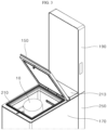
- FIG. 3 is a view illustrating a state in which the door 150 is open in the cup washer according to one embodiment.
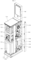
- FIG. 4 is a perspective view illustrating the cup washer from which some components are omitted.
- FIG. 5 is a side view illustrating the cup washer of FIG. 4 .
- the cup washer may include a base plate 110, a water storage tank 120, the washing unit 130, an intermediate plate 140, the door 150, and a frame 160.
- the base plate 110 may be disposed at a lowermost portion of the cup washer to support other components of the cup washer. A lower portion of the base plate 110 may be disposed on the ground.
- the base plate 110 may include a first part 111 and a second part 112. The first part 111 may have a lower surface disposed on the ground and support the second part 112.
- the second part 112 may be disposed on top of the first part 111, and the water storage tank 120 may be disposed on the second part 112.
- the frame 160 may be coupled to the second part 112.
- front supports 161, rear supports 162, and intermediate supports 163 may be coupled to the second part 112. Therefore, the frame 160 may be supported by the second part 112.
- the water storage tank 120 may be disposed on top of the base plate 110 to store water for washing the cup.
- the water storage tank 120 may be connected to the city water supply using a pipe. Therefore, water in the city water supply may flow into the water storage tank 120 and may be stored therein.
- the water storage tank 120 may be connected to the washing unit 130 using a pipe. Therefore, water in the water storage tank 120 may flow into the washing unit 130 and may be used to wash a cup accommodated in the washing unit 130.
- a heating device may be provided inside the water storage tank 120.
- the water in the water storage tank 120 may be heated by the heating device and flow into the washing unit 130. This may increase washing efficiency for the cup by washing the cup using the heated water.
- the water storage tank 120 may be fully filled with water. Therefore, the water storage tank 120 fully filled with water may have a relatively larger load than a load of each of other components.
- the water storage tank 120 may be disposed on the base plate 110 and disposed at the lower portion of the cup washer.
- the cup washer Due to the load of the water storage tank 120 fully filled with water, which is disposed on the lower portion of the cup washer, the overall center of gravity of the cup washer may be lowered. Therefore, the cup washer provided in a tower shape with a relatively larger length in the vertical direction may maintain a stable state without easily tipping over even in the event of an external impact.
- the washing unit 130 may be disposed on top of the water storage tank 120 and wash the accommodated cup. A space for accommodating the cup may be formed in the washing unit 130.
- the washing unit 130 may be connected to the water storage tank 120 using a pipe. Therefore, water for washing may flow into the washing unit 130 from the water storage tank 120.
- the washing unit 130 may be directly connected to the city water supply bypassing the water storage tank 120. Therefore, depending on a user's selection, the cup may be washed using water introduced from the water storage tank 120 or the cup may be washed using water introduced directly from the city water supply.
- the intermediate plate 140 may be disposed between the water storage tank 120 and the washing unit 130 to support the washing unit 130.
- the washing unit 130 may be disposed on top of the intermediate plate 140, and the intermediate plate 140 may support a portion of the load of the washing unit 130.
- the intermediate plate 140 may have substantially a plate-like shape and may be coupled to the frame 160 at an edge thereof to be supported by the frame 160.
- the door 150 may be disposed on top of the washing unit 130 and may be hinge-rotated in the vertical direction to open and close an open upper portion of the washing unit 130. Referring to FIG. 3 , the door 150 may be hinge-rotated in the vertical direction of the cup washer, Therefore, a user may proceed with washing a cup 10 by manually opening the door 150 to put the cup 10 into the washing unit 130 and then closing the door 150.
- the top cover 210 may be provided on an upper end of the washing unit 130.
- the top cover 210 may be disposed on top of the tub 131.
- a portion of the top cover 210 may be coupled to an edge portion of the upper end of the washing unit 130, and the door 150 may be disposed thereon.
- An inlet cover 213 may be provided on the other portion of the top cover 210.
- the inlet cover 213 may open and dose inlets for detergent and rinse out into the washing unit 130 and may be detachably provided on the top cover 210.
- a user may open or close the door 150 disposed on the upper end of the cup washer to put a cup into the washing unit 130 or take the cup out of the washing unit 130. At this time, since the door 150 is hinge-rotated in the vertical direction, the user may conveniently move the door 150 without bending down.
- the door 150 may be provided so that an area of the cup washer is not changed in a state in which the door 150 is open. Therefore, since a planar cross-sectional area of the cup washer is constant regardless of whether the door 150 is opened or closed, no additional space is required to open the door 150.
- the door since the door may be provided to be hinge-rotated in the vertical direction of the cup washer at the upper end of the washing unit 130, the user may conveniently use the cup washer by opening or closing the door 150 without bending down.
- this structure no additional space for opening the door 150 is required, thereby increasing space efficiency.
- the frame 160 may be supported by the base plate 110 and coupled to the intermediate plate 140 and support the washing unit 130.
- the frame 160 may provide an internal space of the cup washer and may be coupled to various components to support these components.
- the frame 160 may include the front supports 161, the rear supports 162, the intermediate supports 163, and top supports 164.
- the components of the frame 160 may withstand loads of the washing unit 130, the door 150, and the like provided on the upper portion of the cup washer.
- a pair of front supports 161 may be disposed to be spaced apart from each other on the front of the cup washer and have lower portions coupled to the base plate 110, and longitudinal directions thereof are disposed in the vertical direction.
- the pair of front supports 161 may be disposed at positions of the front of the cup washer, which are spaced apart from each other in a lateral direction of the cup washer and may form corner portions of the front of the cup washer.
- the front supports 161 may be formed in an L-shaped cross section to form the corner portions of the cup washer.
- the front supports 161 may be coupled to the base plate 110 by fasteners such as screws.
- a pair of rear supports 162 may be disposed to be spaced apart from each other on the rear of the cup washer and have lower portions coupled to the base plate 110, and longitudinal directions thereof are disposed in the vertical direction.
- the pair of rear supports 162 may be disposed at positions of the rear of the cup washer, which are spaced apart from each other in the lateral direction of the cup washer and disposed adjacent to corner portions of the rear of the cup washer.
- the rear supports 162 may be coupled to the base plate 110 by fasteners.
- a pair of intermediate supports 163 may be disposed to be spaced apart from each other, may be disposed between the front supports 161 and the rear supports 162, and may have lower portions coupled to the base plate 110, and longitudinal directions thereof are disposed in the vertical direction.
- the pair of intermediate supports 163 may be disposed at positions of a central portion of the cup washer, which are spaced apart from each other in the lateral direction of the cup washer.
- the intermediate supports 163 may be coupled to the base plate 110 by fasteners.
- the intermediate supports 163 may be coupled to the intermediate plates 140 and the upper supports 164 by the fasteners to stably maintain the positions and support the loads of the components of the cup washer.
- the upper supports 164 may be disposed on top of the front supports 161 and the intermediate supports 163, and a pair of upper supports 164 may be disposed to be spaced apart from each other in the lateral direction, may have longitudinal directions disposed in a front-rear direction, and may be coupled to the washing unit 130.
- the pair of upper supports 164 may be disposed at positions of the upper portion of the cup washer, which are spaced apart from each other in the lateral direction of the cup washer.
- the washing unit 130 may be coupled to the upper supports 164 by fasteners. Therefore, the upper supports 164 may support the load of the washing unit 130.
- a plurality of upper supports 164 may be provided to be spaced apart from each other in the vertical direction of the cup washer. Therefore, in FIG. 5 and the like, an embodiment in which a total of four upper supports 164 including one pair provided at both sides of the cup washer, and one pair provided on the upper and lower portions of the cup washer are provided is illustrated. However, the number of upper supports 164 is not limited thereto.
- Each of the upper supports 164 may be coupled to the front supports 161, the rear supports 162, and the intermediate supports 163. Therefore, the load of the washing unit 130 may be transmitted to the front supports 161, the rear supports 162, and the intermediate supports 163 through the upper supports 164 and finally transmitted to the base plate 110.
- the cup washer may stably support the washing unit 130 provided therein.
- the upper support 164 may be coupled to the front supports 161, the rear supports 162, and the intermediate supports 163 by fasteners such as a screw.
- components provided in the upper portion of the cup washer in addition to the washing unit 130 may be supported by the frame 160, and the components may be ultimately supported by the base plate 110.
- the components may he stably supported by the frame 160 and the base plate 110 even in a state in which relatively heavier components such as the washing unit 130 are provided on the upper portion of the cup washer.
- the cup washer may include a front panel 170 and a rear panel 180.
- the front panel 170 may be disposed on the front of the cup washer to cover the water storage tank 120, the tub 131, and the washing unit 130.
- the front panel 170 may be coupled to the rear support 162. of the frame 160 by a fastener.
- the rear panel 180 may be coupled to the frame 160 to cover the rear of the cup washer.
- a first vent 181 for ventilating an inside and an outside of the cup washer may be provided on the rear panel 180. Air flowing into the drying module 132 to be described below may flow into the cup washer through the first vent 181.
- a handle 260 for a user or a manager to hold the cup washer may be coupled to the rear panel 180 to facilitate the movement of the cup washer.
- the cup washer may include a display unit 190 coupled to an upper portion of the rear support 162 and disposed at one side of the door 150.
- the display unit 190 may be disposed at one side of the upper portion of the cup washer, for example, at one side of the door 150 and provided to protrude from the door 150.
- the user may view the display unit 190 while being positioned in front of the cup washer.
- Various pieces of information on the use of the cup washer may be displayed on the display unit 190 in the form of images, texts, and videos.
- the user may operate the cup washer or know an operating state of the cup washer by looking at the information displayed on the display unit 190.
- a command input device in which commands are inputted by, for example, a capacitive touch method may be provided on the display unit 190. Therefore, the user may control the operation of the cup washer using the display unit 190.
- the cup washer may include a first circuit board 220 and a board support 230.
- the first circuit board 220 may be disposed at one side of the water storage tank 120, for example, behind the water storage tank 120, and may include a controller for controlling the operation of the cup washer.
- the first circuit board 220 may be disposed at the one side of the water storage tank 120 on the lower portion of the cup washer in which an extra space is formed due to the arrangement of the water storage tank 120 having a relatively smaller volume than the washing unit 130.
- a lower portion of the board support 230 may be coupled to the base plate 110, an upper portion thereof may be coupled to the intermediate plate 140, and the first circuit board 220 may be coupled to the board support 230.
- the board support 230 may be stably coupled to the base plate 110 by a fastener.
- the board support 230 may be used not only to fix the first circuit board 220, but also to fix a pipe disposed on the lower portion of the cup washer.
- the cup washer may include an exterior part 250 coupled to the rear panel 180 to cover the rear support 162.
- a plurality of fasteners may be coupled to the rear support 162. for coupling with other components of the cup washer.
- the exterior part 250 may cover the rear support 162 and may be coupled to a relatively very fewer number of fasteners when compared to the rear support 162. With this structure, the exterior part 250 may be disposed outside the cup washer at a position corresponding to the rear support 162 to improve the simple look of the cup washer.
- FIG. 6 is a perspective view illustrating the washing unit 130 according to one embodiment.
- FIG. 7 is a front view illustrating the washing unit 130 according to one embodiment.
- FIG. 8 is a side view illustrating the washing unit 130 according to one embodiment.
- FIG. 9 is a rear view illustrating the washing unit 130 according to one embodiment.
- the washing unit 130 may include the tub 131, the drying module 132, a sump 133, a circulation pump 134, and a water discharging pump 135.
- the tub 131 may be disposed above the water storage tank 120 to provide a space in which a cup is accommodated, and washing water may be sprayed.
- a rack on which a cup is mounted may be provided inside the tub 131, and a spray device for spraying water may be provided on a lower portion of the tub 131.
- An open upper end of the tub 131 may be opened and closed by the door 150.
- the drying module 132 may be disposed on one side of the tub 131 to be connected to the tub 131 and may spray heated air for drying to an inside of the tub 131. After the washing of the cup 10 with water is completed, water remains on surfaces of the cup. The drying module 132 may dry the cup by spraying the heated air, that is, hot air to the cup to dry the cup to remove any remaining water.
- a heating device for heating air flowing into the drying module 132 may be provided in the drying module 132.
- a blowing fan 1321 for forcing air to flow through a flow path formed in the drying module 132 may be provided in the drying module 132.
- the sump 133 may be disposed under the tub 131 to be connected to the tub 131 to store the water sprayed in the tub 131.
- the water stored in the sump 133 may be sprayed by the spray device from the tub 131 while circulating between the tub 131 and the sump 133 by the circulation pump 134 to wash the cup 10 accommodated in the tub 131.
- the circulation pump 134 may be disposed under the tub 131 to be connected to the tub 131 and the sump 133 to circulate water between the tub 131 and the sump 133.
- the circulation pump 134 may force water to flow from the sump 133 to the tub 131.
- the circulation pump 134 may be connected to the spray device disposed under the tub 131. Therefore, when the circulation pump 134 operates, the water stored in the sump 133 may flow into the spray device and may be sprayed into the tub 131 by the spray device to wash the cup.
- the water discharging pump 135 may be disposed under the tub 131 to be connected to the sump 133 to discharge water from the sump 133 to the outside. When the washing of the cup with water is completed, the water discharging pump 135 may operate so that the water stored in the sump 133 may be discharged to the outside of the cup washer through a drainpipe connected to the water discharging pump 135.
- a washing process of the cup 10 with the water stored in the water storage tank 120 is as follows. Water may flow into the water storage tank 120 from the city water supply through a pipe and may be stored therein. The water in the water storage tank 120 may be heated by the heating device provided in the water storage tank 120. Heated water in the water storage tank 120 may flow into the tub 131 through a pipe and may be stored in the sump 133 disposed under the tub 131.
- hot water may be sprayed from the sump 133 into the tub 131 through the spray device to wash the cup.
- the hot water sprayed into the tub 131 may re-flow into the sump 133, re-flow into the spray device by the circulation pump 134, and may be sprayed into the tub 131 by the spray device.
- the circulation pump 134 may be stopped, and the water discharging pump 135 may be operated to discharge the water stored in the sump 133 to the outside.
- the drying module 132 may be operated to blow hot air into the tub 131, and after the spraying of the hot air is performed for a set time, a cup washing operation including a drying process may be completed.
- the cup washer may perform washing with detergent and then rinsing with rinse.
- a structure provided to input the detergent and the rinse into the tub 131 will be described in detail.
- the washing process using detergent and the rinsing process using rinse may be separated from each other. After a process of washing the cup by mixing detergent with hot water is completed, the water in the sump 133 contains detergent and foreign substances. Therefore, the contaminated water may be discharged to the outside by operating the water discharging pump 135.
- the rinsing operation may be performed by allowing water to re-flow into the sump 133 and mixing the water with the rinse to operate the circulation pump 134. This may increase washing efficiency of the cup washer by separating the washing process using the detergent and the rinsing process using the rinse from each other.
- the washing unit 130 may include a detergent storage 136, a rinse storage 137, a detergent injection part 138, a rinse injection part 139, a detergent pump 1301, and a rinse pump 1302.
- the detergent storage 136 may be disposed in rear of the tub 131 so as to store the detergent therein.
- the rinse storage 137 may be disposed behind the tub 131 separately from the detergent storage 136 and may store the rinse therein. Therefore, the detergent and the rinse may not be mixed with each other.
- a detergent inlet 211 into which detergent is input and a rinse inlet 212 into which rinse is input may be provided on the top cover 210.
- the detergent inlet 211 may be connected to the detergent storage 136, and the rinse inlet 212 may be connected to the rinse storage 137. Therefore, the detergent and the rinse introduced through the detergent inlet 211 and the rinse inlet 212 may be stored in the detergent storage 136 and the rinse storage 137.
- the detergent injection part 138 may be connected to the detergent storage 136 and the tub 131 to inject the detergent into the tub 131.
- An inlet of the detergent injection part 138 may be connected to the detergent storage 136 and an outlet thereof may be connected to the tub 131.
- the rinse injection part 139 may be connected to the rinse storage 137 and the tub 131 to inject the rinse into the tub 131.
- An inlet of the rinse injection part 139 may be connected to the rinse storage 137 and an outlet thereof may be connected to the tub 131.
- the detergent pump 1301 may be connected to the detergent injection part 138 to pump the detergent to the tub 131.
- the rinse pump 1302. may be connected to the rinse injection part 139 to pump the rinse to the tub 131. Operations of the detergent pump 1301 and the rinse pump 1302 may be controlled by the controller.
- the controller may operate the detergent pump 1301 to mix the detergent with water in the washing process and operate the rinse pump 1302 to mix the rinse with water in the rinsing process.
- the water storage tank 120 may be connected to the tub 131 using a pipe and provided so that the water in the water storage tank 120 flows into the tub 131. Therefore, the water in the water storage tank 120 may flow into the tub 131 after being heated to become hot water and may be stored in the sump 133 until the circulation pump 134 operates.
- the tub 131 may also have a water supply path directly connected to the city water supply. Therefore, normal washing or rapid washing may be performed on the cup by the user's selection.
- the cup In normal washing, the cup may be washed using the hot water heated in the water storage tank 120, and the cup may be cleanly washed using detergent and rinse, but it may take a relatively longer time.
- FIG. 10 is a view illustrating a detergent injection device and a rinse injection device according to one embodiment.
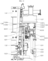
- FIG. 11 is a bottom view illustrating the detergent injection device and the rinse injection device.
- the cup washer may include the washing unit 130 for washing the accommodated cup 10.
- the washing unit 130 may include the tub 131 which provides a space in which the cup 10 is accommodated and in which washing water is sprayed.
- the washing unit 130 may include the detergent injection device for injecting detergent into the tub 131 and the rinse injection device for injecting rinse into the tub 131.
- the cup may be washed by the detergent mixed with water and sprayed to the cup.
- the cup may be rinsed after the cup is washed by the rinse mixed with water and sprayed to the cup.
- the rinse may be used to rinse the cup after the detergent is used to wash the cup. That is, the detergent and the rinse may be mixed with the water sprayed to the tub 131 with a time difference.
- the detergent and the rinse may be provided in a liquid state and pumped by the detergent pump 1301 and the rinse pump 1302 to flow into the tub 131.
- the detergent injection device and the rinse injection device may be disposed outside the tub 131.
- the detergent injection device may include the detergent storage 136, the detergent injection part 138, and the detergent pump 1301.
- the detergent storage 136 may be disposed on one side of the tub 131 so as to store therein detergent.
- a manager may periodically pour detergent into the detergent storage 136 to store the detergent in the detergent storage 136.
- the detergent injection part 138 may be coupled to a bottom of the detergent storage 136 to inject the detergent in the detergent storage 136 into the detergent pump 1301. Since the detergent injection part 138 is disposed under the detergent storage 136, detergent may be collected in the detergent injection part 138 by gravity and injected into the detergent pump 1301.
- the detergent pump 1301 may be connected to the detergent injection part 138 to pump the detergent to the tub 131.
- the operation of the detergent pump 1301 may be controlled by the controller provided in the cup washer.
- the detergent pump 1301 may operate at a set time point to pump the detergent introduced from the detergent injection part 138 to the tub 131.
- the detergent pump 1301 may include a first body 611, a first connector 612, and a detergent discharge part 613.
- the first body 611 may include a motor for providing a pumping force for discharging detergent, a gear device connecting the motor to discharging devices of the detergent discharge part 613, and the like therein.
- the first connector 612 may be coupled to the first body 611 and connected to the detergent injection part 138 so that detergent may be introduced from the detergent injection part 138.
- the first connector 612 may connect the detergent injection part 138 to the detergent discharge part 613.
- One side of the detergent discharge part 613 may be connected to the first connector 612 and the other side thereof may be connected to the tub 131 to discharge detergent into the tub 131.
- a pipe may be connected to the other side of the detergent discharge part 613 so that the detergent discharged from the detergent discharge part 613 may be injected into the tub 131 through the pipe.
- the detergent discharge part 613 may include the detergent pumping part 6131 and a detergent injection nozzle 6132,
- the detergent pumping part 6131 may be connected to the first connector 612. to pump the detergent introduced from the first connector 612.
- the detergent pumping part 6131 may be driven by receiving a driving force from a motor provided in a body to generate a pumping force and pump the detergent flowing into the first connector 612 to the tub 131.
- the detergent injection nozzle 6132 may be coupled to the detergent pumping part 6131 and connected to the tub 131.
- a pipe connected to the tub 131 may be mounted on one end portion of the detergent injection nozzle 6132.
- the detergent injection nozzle 6132 may inject detergent into the tub 131.
- the detergent injection nozzle 6132 may be formed to have a smaller inner diameter than the detergent pumping part 6131 has and connected to the pipe.
- FIG. 12 is a side view illustrating a portion of the washing unit 130.
- FIG. 13 is a side view illustrating the portion of the washing unit of FIG. 12 in an opposite direction.
- the rinse injection device may include the rinse storage 137, the rinse injection part 139, and the rinse pump 1302.
- the detergent injection device and the rinse injection device may have a similar outer shape, and some components thereof may be symmetrically arranged with each other in the horizontal direction and the vertical direction.
- the rinse storage 137 may be disposed on the one side of the tub 131 separately from the detergent storage 136 to store rinse.
- the manager may periodically pour rinse into the rinse storage 137 to store the rinse in the rinse storage 137.
- the rinse injection part 139 may be coupled to a bottom of the rinse storage 137 to inject the rinse in the rinse storage 137 into the rinse pump 1302. Since the rinse injection part 139 is disposed on the lower portion of the rinse storage 137, rinse may be collected in the rinse injection part 139 by gravity and injected into the rinse pump 1302.
- the rinse pump 1302 may be connected to the rinse injection part 139 to pump the rinse to the tub 131.
- the operation of the rinse pump 1302 may be controlled by the controller provided in the cup washer.
- the rinse pump 1302. may operate at a set time point to pump the rinse introduced from the rinse injection part 139 to the tub 131.
- the rinse pump 1302 may include a second body 621, a second connector 622, and a rinse discharge part 623.
- the second body 621 may include a motor for providing a pumping force for discharging rinse, a gear device connecting the motor to discharging devices of the rinse discharge part 623, and the like therein.
- the second connector 622 may be coupled to the second body 621 and connected to the rinse injection part 139 so that rinse may be introduced from the rinse injection part 139.
- the second connector 622 may connect the rinse injection part 139 to the rinse discharge part 623.
- One side of the rinse discharge part 623 may be connected to the second connector 622 and the other side thereof may be connected to the tub 131 to discharge rinse into the tub 131.
- a pipe may be connected to the other side of the rinse discharge part 623 so that the rinse discharged from the rinse discharge part 623 may be injected into the tub 131 through the pipe.
- the rinse discharge part 623 may include a rinse pumping part 6231 and a rinse injection nozzle 6232.
- the rinse pumping part 6231 may be connected to the second connector 622 to pump the rinse introduced from the second connector 622.
- the rinse pumping part 6231 may be driven by receiving a driving force from a motor provided in a body to generate a pumping force and pump the rinse flowing into the second connector 622 to the tub 131.
- the rinse injection nozzle 6232 may be coupled to the rinse pumping part 6231 and connected to the tub 131.
- a pipe connected to the tub 131 may be mounted on one end portion of the rinse injection nozzle 6232.
- the rinse injection nozzle 6232 may inject rinse into the tub 131.
- the rinse injection nozzle 6232 may be formed to have a smaller inner diameter than the rinse pumping part 6231 has and connected to the pipe.
- the detergent injection device and the rinse injection device may be separately disposed outside the tub 131 in the washing unit 130. Water flowing into the tub 131 may be mixed with detergent or rinse by the detergent injection device or the rinse injection device.
- the washing water in which water and detergent are mixed may be sprayed to the cup, thereby increasing the washing efficiency for the cup.
- the washing water in which water and rinse are mixed may be sprayed to the cup to effectively rinse the cup.
- each of the detergent pump 1301 and the rinse pump 1302 may be connected to the controller provided in the cup washer and may operate at a time set by the controller to inject each of the detergent and the rinse into the tub 131 so as to be mixed with water in the tub 131.
- a manager may periodically replenish the detergent and the rinse in the detergent storage 136 and the rinse storage 137, respectively.
- a user who intends to wash his/her cup may conveniently use detergent, thereby increasing the washing efficiency for the cup, and cleanly rinse the cup using rinse after washing the cup without having to perform a separate operation for adding detergent and rinse to water.
- FIG. 14 is a perspective view illustrating the detergent injection part 138 according to one embodiment.
- FIG. 15 is a view illustrating the detergent injection part of FIG. 14 in a different direction from a view direction of FIG. 14 .
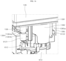
- FIG. 16 is a view illustrating a portion of the detergent injection device.
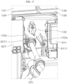
- FIG. 17 is a view illustrating a portion of the washing unit 130.
- the detergent injection part 138 may include a first lower cover 1381 and a first connection portion 1382.
- the first lower cover 1381 may be coupled to the lower portion of the detergent storage 136 to cover an open lower surface of the detergent storage 136. Since the first lower cover 1381 covers a lower surface of the detergent storage 136, liquid detergent stored in the detergent storage 136 may be moved down by gravity and disposed on an upper surface of the first lower cover 1381.
- the first connection portion 1382 may protrude downwardly from the first lower cover 1381, may be coupled to the first connector 612, and may have a first flow hole 1382a through which detergent flows formed therein.
- the detergent disposed on the upper surface of the first lower cover 1381 may flow into the first connector 612 through the first flow hole 1382a provided in the first connection portion 1382.
- the upper surface of the first lower cover 1381 may be formed to be inclined to have a reduced height toward the first flow hole 1382a. Therefore, the liquid detergent disposed on the upper surface of the first lower cover 1381 may be collected to an inlet of the first flow hole 1382a disposed at the lowest position of the inclined upper surface of the first lower cover 1381 after flowing along the upper surface of the first lower cover 1381 by gravity.
- the detergent collected to the inlet of the first flow hole 1382a may move down through the first flow hole 1382a to pass through the first connector 612 and flow into the detergent discharge part 613 and may be pumped by the detergent pumping part 6131 to flow into the tub 131 through the detergent injection nozzle 6132 and the pipe.
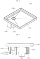
- FIG. 18 is a perspective view illustrating the rinse injection part 139 according to one embodiment.
- FIG. 19 is a view illustrating the rinse injection part of FIG. 18 in a different direction from a view direction of FIG. 18 .
- FIG. 20 is a view illustrating a portion of the rinse injection device.
- the rinse injection part 139 may include a second lower cover 1391 and a second connection portion 1392.
- the second lower cover 1391 may be coupled to the lower portion of the rinse storage 137 to cover an open lower surface of the rinse storage 137. Since the second lower cover 1391 covers the lower surface of the detergent storage 137, liquid rinse stored in the rinse storage 137 may be moved down by gravity and disposed on an upper surface of the second lower cover 1391.
- the second connection portion 1392 may protrude downwardly from the second lower cover 1391, may be coupled to the second connector 622, and may have a second flow hole 1392a through which rinse flows formed therein.
- the rinse disposed on the upper surface of the second lower cover 1391 may flow into the second connector 622 through the second flow hole 1392a provided in the second connection portion 1392.
- the upper surface of the second lower cover 1391 may be formed to be inclined to have a reduced height toward the second flow hole 1392a. Therefore, the liquid rinse disposed on the upper surface of the second lower cover 1391 may be collected to an inlet of the second flow hole 1392a disposed at the lowest position of the inclined upper surface of the second lower cover 1391 after flowing along the upper surface of the second lower cover 1391 by gravity.
- the rinse collected to the inlet of the second flow hole 1392a may flow down through the second flow hole 1392a to pass through the second connector 622 and flow into the rinse discharge part 623 and may be pumped by the rinse pumping part 6231 to flow into the tub 131 through the rinse injection nozzle 6232 and the pipe.
- the tub 131 may include a detergent inlet 1312 and a washing water inlet 1315.
- the detergent inlet 1312 may be connected to the detergent injection nozzle 6132 with a pipe, and detergent may flow into the tub 131 from the detergent injection nozzle 6132. Detergent discharged from the detergent discharge part 613 may flow into the tub 131 through the detergent inlet 1312.
- the washing water inlet 1315 may be disposed above the detergent inlet 1312, and water may flow into the tub 131.
- the washing water inlet 1315 may be connected to the water storage tank 120 with a pipe, and hot water from the water storage tank 120 may flow into the tub 131 through the washing water inlet 1315.
- FIG. 49 is a view illustrating a structure in which a pipe is connected to the washing unit 130.
- the cup washer may include the water storage tank 120, a first connecting pipe 631, a second connecting pipe 632, and a three-way fitting 633.
- the water storage tank 120 may be disposed under the washing unit 130 to store water for washing the cup.
- the first connecting pipe 631 may connect the washing water inlet 1315 to the water storage tank 120. Water in the water storage tank 120 may be heated by a heating device to flow into the tub 131 through the first connecting pipe 631 and the washing water inlet 1315.
- the second connecting pipe 632 may connect the rinse injection nozzle 6232 to the first connecting pipe 631.
- the three-way fitting 633 may be mounted on the first connecting pipe 631, and one end of the second connecting pipe 632 may be mounted thereon. Therefore, the rinse discharged from the rinse injection nozzle 6232 may be mixed with the water flowing through the first connecting pipe 631 at the three-way fitting 633, and the water mixed with rinse may flow into the tub 131 through the washing water inlet 1315.
- the rinse discharged from the rinse injection nozzle 6232 may flow into the first connecting pipe 631 from the second connecting pipe 632 and may be mixed with the water flowing through the first connecting pipe 631 to flow into the tub 131.
- water mixed with filth and detergent stored in the sump 133 may be drained to the outside of the cup washer using the water discharging pump 135. Thereafter, hot water from the water storage tank 120 may re-flow into the tub 131 through the washing water intel. 1315 and may be stored in the sump 133 under the tub 131.
- the cap may be rinsed by spraying water to the cup accommodated in the tub 131 while circulating the water stored in the sump 133 between the tub 131 and the sump 133 using the circulation pump 134.
- the rinse may be mixed with water.
- the rinse When water flows into the tub 131 from the water storage tank 120 and is filled in the sump 133 for the rinsing operation, the rinse may be simultaneously pumped at a time point at which the water flows through the first connecting pipe 631. At this time, the second connecting pipe 632 through which the rinse flows may be connected to the first connecting pipe 631 through the three-way fitting 633, and thus the rinse may be mixed with water to flow into the tub 131.
- water and rinse are mixed to flow together, and when the water and the rinse continuously flow and are stored in the sump 133, the water and the rinse are further mixed so that the water and the rinse may become a state of being uniformly mixed in the sump 133.
- the rinse may be used for the rinsing operation of washing off the detergent remaining on the surfaces of the cup after the washing operation using detergent is completed. Therefore, the detergent and the rinse need to be separated without being mixed with each other in the entire process of washing the cup.
- the detergent inlet 1312 separated from the washing water inlet 1315 may be formed in the tub 131, and the detergent injection nozzle 6132 and the detergent inlet 1312 may be connected to a separate pipe different from the first connecting pipe 631 or the second connecting pipe 632.
- the rinse may flow into the tub 131 through the second connecting pipe 632, the three-way fitting 633, the first connecting pipe 631, and the washing water inlet 1315.
- detergent may be introduced into the tub 131 through the detergent inlet 1312 connected to the detergent injection nozzle 6132 through the separate pipe.
- a time point at which the detergent flows into the tub 131 and a time point at which the rinse flows into the tub 131 may be different from each other.
- water and rinse may meet and flow in one pipe to flow into the tub 131 through the washing water inlet 1315. Therefore, the water and the rinse may be more uniformly mixed while flowing, and the washing water in which the water and the rinse are uniformly mixed may be sprayed to the cup, and thus the rinsing operation of the cup may be effectively performed.
- the cup washer may include the drying module 132, the sump 133, the circulation pump 134, and the water discharging pump 135.
- the drying module 132 may be disposed on a side surface portion of the tub 131 to be connected to the tub 131 to blow heated air into the tub 131. After the above-described washing operation and rinsing operation are performed, the drying module 132. may be operated to dry the cup with the water remaining on the surfaces of the cup accommodated in the tub 131.
- the sump 133 may be disposed under the tub 131 to be connected to the tub 131 to store the water sprayed from the tub 131.
- the circulation pump 134 may be disposed under the tub 131 to be connected to the tub 131 and the sump 133 to circulate water between the tub 131 and the sump 133.
- the cup accommodated in the tub 131 may be washed or rinsed by operating the circulation pump 134 to circulate and spray water to the tub 131.
- the water discharging pump 135 may be disposed under the tub 131 to be connected to the sump 133 to discharge water from the sump 133 to the outside. After completing the washing operation or the rinsing operation, the water stored in the sump 133 may be discharged to the outside of the cup washer through the water discharging pump 135.
- the detergent injection part 138 may include a (1-1)-st cover coupling protrusion 1383, a (1-2)-nd cover coupling protrusion 1384, and a (1-3)-rd cover coupling protrusion 1385.
- the (1-1)-st cover coupling protrusion 1383 may protrude from the first lower cover 1381 and may be coupled to the tub 131.
- a coupling protrusion may protrude at a position corresponding to the (1-1)-st cover coupling protrusion 1383, and the (1-1)-st cover coupling protrusion 1383 and the coupling protrusion of the tub 131 may be coupled by a fastener such as a screw.
- the (1-2)-nd cover coupling protrusion 1384 may protrude from the first lower cover 1381 and may be coupled to the first connector 612.
- the (1-3)-rd cover coupling protrusion 1385 may protrude from the first lower cover 1381, and a first hook-receiving groove 1385a may be formed in the (1-3)-rd cover coupling protrusion 1385.
- the first connector 612 may include a first fastening portion 6121 and a first coupling hook 6122.
- the first fastening portion 6121 may be formed to protrude laterally from the first connector 612 to be fastened to the (1-2)-nd cover coupling protrusion 1384.
- the (1-2)-nd cover coupling protrusion 1384 may include a first large-diameter portion 1384a having a relatively larger outer diameter, and a first small-diameter portion 1384b protruding from the first large-diameter portion 1384a and having a relatively smaller outer diameter.
- a hole into which a fastener is fastened may be formed in each of the first large-diameter portion 1384a and the first small-diameter portion 1384b.
- a hole may be formed in the first fastening portion 6121 of the first connector 612, and the first small-diameter portion 1384b of the (1-2)-nd cover coupling protrusion 1384 may be inserted into the hole of the first fastening portion 6121.
- the (1-2)-nd cover coupling protrusion 1384 and the first fastening portion 6121 may be coupled by a fastener.
- the first coupling hook 6122 may be inserted into the first hook-receiving groove 1385a and coupled to the (1-3)-rd cover coupling protrusion 1385.
- the first hook-receiving groove 1385a may be formed to have a predetermined length in a vertical direction of the detergent injection part 138.
- the first coupling hook 6122 may be inserted into the first hook-receiving groove 1385a by moving in a longitudinal direction of the first hook-receiving groove 1385a, that is, the vertical direction of the detergent injection part 138.
- the first coupling hook 6122 may be formed not to be easily separated from the first hook-receiving groove 1385a when moving down in a state of being inserted into the first hook-receiving groove 1385a. Therefore, the (1-3)-rd cover coupling protrusion 1385 may stably maintain a state of being coupled to the first connector 612 without a fastener.
- the detergent pump 1301 may be coupled to the drying module 132.
- a (1-1)-st module fastening portion 6111 may be provided in the first body 611 of the detergent pump 1301, and a (1-2)-nd module fastening portion 132a may be provided in the drying module 132.
- the (1-1)-st module fastening portion 6111 may be formed to protrude in a lateral direction of the first body 611 and fastened to the drying module 132.
- the (1-2)-nd module fastening portion 132a may protrude from the drying module 132 toward the (1-1)-st module fastening portion 6111, and the (1-1)-st module fastening portion 6111 may be fastened thereto.
- the (1-2)-nd module fastening portion 132a and the (1-1)-st module fastening portion 6111 may be coupled by a fastener.
- a portion of the detergent injection device may be coupled to the tub 131 and the other portion thereof may be coupled to the drying module 132.
- the drying module 132 may be disposed between the tub 131 and the detergent injection device, and at least portions of the drying module 132 and the detergent injection device may be disposed to overlap each other.
- the drying module 132 and the detergent injection device are disposed may be reduced to increase the space efficiency of the cup washer.
- the detergent injection device is coupled to both the drying module 132 and the tub 131 to firmly couple the drying module 132 to the tub 131.
- the rinse injection part 139 may include a (2-1)-st cover coupling protrusion 1393, a (2-2)-nd cover coupling protrusion 1394, and a (2-3)-rd cover coupling protrusion 1395.
- the (2-1)-st cover coupling protrusion 1393 may protrude from the second lower cover 1391 and may be coupled to the tub 131.
- a coupling protrusion may protrude at a position corresponding to the (2-1)-st cover coupling protrusion 1393, and the (2-1)-st cover coupling protrusion 1393 and the coupling protrusion of the tub 131 may be coupled by a fastener such as a screw.
- the (2-2)-nd cover coupling protrusion 1394 may protrude from the second lower cover 1391 and may be coupled to the second connector 622.
- the (2-3)-rd cover coupling protrusion 1395 may protrude from the second lower cover 1391, and a second hook-receiving groove 1395a may be formed in the (2-3)-rd cover coupling protrusion 1395.
- the second connector 622 may include a second fastening portion 6221 and a second coupling hook 6222.
- the second fastening portion 6221 may be formed to protrude laterally from the second connector 622 to be fastened to the (2-2)-nd cover coupling protrusion 1394.
- the (2-2)-nd cover coupling protrusion 1394 may include a second large-diameter portion 1394a having a relatively larger outer diameter, and a second small-diameter portion 1394b protruding from the second large-diameter portion 1394a and having a relatively smaller outer diameter.
- a hole into which a fastener is fastened may be formed in each of the second large-diameter portion 1394a and the second small-diameter portion 1394b.
- a hole may he formed in the second fastening portion 6221 of the second connector 622, and the second small-diameter portion 1394b of the (2-2)-nd cover coupling protrusion 1394 may be inserted into the hole of the second fastening portion 6221.
- the (2-2)-nd cover coupling protrusion 1394and the second fastening portion 6221 may he coupled by a fastener.
- the second coupling hook 6222 may be inserted into the second hook-receiving groove 1395a and coupled to the (2-3)-rd cover coupling protrusion 1395.
- the second hook-receiving groove 1395a may he formed to have a predetermined length in a vertical direction of the rinse injection part 139.
- the second coupling hook 6222 may move in a longitudinal direction of the second hook-receiving groove 1395a, that is, the vertical direction of the rinse injection part 139 and may be inserted into the second hook-receiving groove 1395a.
- the second coupling hook 6222 may be formed not to be easily separated from the second hook-receiving groove 1395a when moving down in a state of being inserted into the second hook-receiving groove 1395a. Therefore, the (2-3)-rd cover coupling protrusion 1395 may stably maintain a state of being coupled to the second connector 622 without a fastener.
- the rinse pump 1302 may be coupled to the drying module 132.
- a (2-1)-st module fastening portion 6211 may be provided in the second body 621 of the rinse pump 1302, and a (2-2)-nd module fastening portion 132b may be provided in the drying module 132.
- the (2-1)-st module fastening portion 6211 may be formed to protrude in a lateral direction of the second body 621 and fastened to the drying module 132.
- the (2-2)-nd module fastening portion 132b may protrude from the drying module 132 toward the (2-1)-st module fastening portion 6211, and the (2-1)-st module fastening portion 6211 may be fastened thereto.
- the (2-2)-nd module fastening portion 132b and the (2-1)-st module fastening portion 6211 may be coupled by a fastener.
- a portion of the rinse injection device may be coupled to the tub 131 and the other portion thereof may be coupled to the drying module 132.
- the drying module 132 may be disposed between the tub 131 and the rinse injection device, and at least portions of the drying module 132 and the rinse injection device may be disposed to overlap each other.
- the rinse injection device is coupled to both the drying module 132 and the tub 131 so as to firmly couple the drying module 132 to the tub 131.
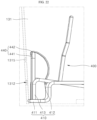
- FIG. 22 is a side view illustrating a portion of the rack 400 according to one embodiment.
- the washing water inlet 1315 may be disposed at a position spaced apart from the detergent inlet 1312 and disposed above the detergent inlet 1312. Therefore, the water flowing into the washing water inlet 1315 does not meet the detergent flowing into the tub 131, and the water may flow into the sump 133 under the tub 131, and likewise, the detergent may also flow into the sump 133, and then the detergent and the water may be mixed.
- the water Since the flow of water is not somewhat active in a state of being stored in the sump 133, the water may not be well mixed with the detergent when the water and the detergent are mixed in the sump 133.
- the tub 131 may include the washing water inlet 1315 and the detergent inlet 1312.
- the washing water inlet 1315 and the detergent inlet 1312 may be formed on the rear of the tub 131.
- the detergent inlet 1312 may be formed to pass through the one side of the tub 131 and may become a passage through which detergent flows into the tub 131.
- the washing water inlet 1315 may be disposed above the detergent inlet 1312 and may become a passage through which water flows into the tub 131.
- the washing unit 130 may include the rack 400.
- the rack 400 may be provided inside the tub 131, the cup may be seated on the rack 400, and the rack 400 may be formed by coupling a plurality of wires.
- a cup, a cup lid, a straw, or the like may be mounted on the rack 400.
- the cup may be mounted upside down on the rack 400. That is, an open inlet of the cup may be disposed on the lower portion of the rack 400, and the bottom of the cup may be disposed on the upper portion of the rack 400. Therefore, water sprayed upward from a lower side of the rack 400 may smoothly flow into the cup to wash the inside of the cup.
- the rack 400 may be formed in a three-dimensional mesh structure by entirely coupling wires. With this shape, a cup or the like may be easily mounted on the rack 400, and the sprayed water may easily wash the cup or the like mounted on the rack 400 with passing through the lower portion of the rack 400.
- the rack 400 may include the bottom portion 410.
- the bottom portion 410 may be seated on the bottom of the tub 131 and support the cup seated on the rack 400 from a lower side.
- the bottom portion 410 may be provided in a shape that is widely spread in front-rear and left-right directions in the lateral direction of the tub 131.
- the bottom portion 410 may include an edge portion 411, a first inclined portion 412, and a first bent portion 413.
- the edge portion 411 may form edges of the bottom portion 410, and portions at both sides thereof may be formed to protrude upward from the tub 131.
- the first inclined portion 412 may extend in a longitudinal direction inclined with respect to the lateral direction of the tub 131.
- a plurality of first inclined portions 412 may be provided to be disposed at positions spaced apart from each other. Therefore, the plurality of first inclined portions 412 may form a bottom surface of the rack 400 on which the cup or the like is mounted.
- each of the plurality of first inclined portions 412 has an inclination
- the cup disposed on the first inclined portions 412 may be mounted on the rack 400 entirely, obliquely with respect to the vertical direction of the tub 131.
- the first bent portion 413 may be bent from the first inclined portion 412 and coupled to the edge portion 411.
- the first bent portion 413 may be formed on one end portion of the first inclined portion 412 in order for the first inclined portion 412 to become a structure having an inclination.
- a plurality of first bent portions 413 may be provided, in which the first bent portions 413 may be disposed to be spaced apart from each other, and each of the first bent portions 413 may extend from each of the first inclined portions 412.
- the rack 400 may include a first flow path guide 440.
- the first flow path guide 440 may be coupled to the bottom portion 410 and disposed to face the washing water inlet 1315 so that the water flowing from the washing water inlet 1315 flows toward the detergent flowing into the detergent inlet 1312.
- the first flow path guide 440 may be disposed on the rear of the tub 131 and disposed at a position adjacent to the washing water inlet 1315. Therefore, the water flowing into the washing water inlet 1315 and pouring into the tub 131 may collide with the first flow path guide 440, and thus the flow path of the water may be changed.
- the first flow path guide 440 may include a base portion 441 and a first pad 442.
- the base portion 441 may be coupled to the bottom portion 410.
- the base portion 441 may be formed to protrude from a rear of the bottom portion 410 and formed by entirely bending a wire.
- the first pad 442 may be coupled to the base portion 441 and disposed at a position corresponding to the washing water inlet 1315 to change a flow direction of the water flowing into the tub 131.
- the first pad 442 may be formed in a curved shape when viewed in cross section to guide water to flow downward of the tub 131.
- the first pad 442 may be disposed to directly face the washing water inlet 1315, Therefore, since the water flowing into the washing water inlet 1315 is sprayed toward the first pad 442 and may collide with the first pad 442, the flow direction of the water may be changed downward of the tub 131.
- the first pad 442 may be formed to have a curved cross section, and the first pad 442 may have a curved surface so that a lower end portion faces the washing water inlet 1315. Therefore, the water colliding with the first pad 442 may approach the wall surface of the tub 131 while flowing downward by gravity.
- the detergent inlet 1312 may be disposed under the washing water inlet 1315. Since the detergent introduced through the detergent inlet 1312 has a relatively higher viscosity, the detergent may flow down along the wall surface of the tub 131.
- the water colliding with the first pad 442 approaches the wall surface of the tub 131 while flowing downward, the water may meet the detergent flowing down the wall surface of the tub 131. Therefore, the water flowing inside the tub 131 may meet the detergent.
- the controller provided in the cup washer may control the operation of the detergent pump 1301 so that the detergent flows into the tub 131 at a time point at which the water flows into the tub 131 through the washing water inlet 1315. Therefore, since the flowing water and the detergent are mixed with each other, the water may be easily mixed with the detergent.
- the rack 400 may include the first flow path guide 440 for guiding the flow direction of water at a position adjacent to the washing water inlet 1315 of the tub 131. Therefore, the water flowing into the tub 131 may flow toward the detergent flowing into the tub 131 by the first flow path guide 440. Therefore, the flowing water is mixed with the detergent, such that the water is easily mixed with the detergent, thereby increasing the washing efficiency of the cup washer.
Landscapes
- Engineering & Computer Science (AREA)
- Water Supply & Treatment (AREA)
- Detail Structures Of Washing Machines And Dryers (AREA)
- Cleaning By Liquid Or Steam (AREA)
Abstract
Description
- The present disclosure relates to a cup washer, and more specifically, to a cup washer for washing a cup carried by a user.
- Contents described in this section simply provide background information on the present disclosure and do not constitute the related art.
- Recently, in order to prevent environmental pollution, the frequency of provision of disposable cups to customers is reduced at stores where beverages are sold, and the trend in which a customer who visits a store carries a multi-use cup, such as a tumbler, and takes out the multi-use cup filled with a beverage is increasing.
- In order to provide convenience to customers, that is, users of multi-use cups, it is necessary to provide a cup washer for washing a cup carried by the user in a store and allow the user to conveniently wash the cup carried by the user.
- Therefore, the cup washer capable of cleaning the cup carried by the user is placed in the store such that the user cleans his or her cup in the store using the cup washer to provide the convenience. The cup washer needs to have a structure such that the cup washer may be easily used by anyone.
- The related art related to a cup washer is disclosed in
Korean Patent Application Laid-Open No. 10-020-0016470 - A cup washing process may largely include a washing step of spraying water to the cup to wash the cup, and then, a rinsing step of spraying clean water to the cup again to rinse the cup.
- For clean washing of the cup, the washing step may be performed using a mixture of detergent with water, and the rinsing step may be performed using a mixture of a rinse with water.
- However, in the prior art, only the washing of the cup using steam is disclosed. In particular, the prior art discloses washing the cup without using a detergent. Accordingly, a cup cleaning method using the detergent cannot be derived from the prior art.
- In washing the cup using the cup washer, it is necessary to inject the detergent and the rinse into a washing unit in order to clean the cup. Accordingly, a device for injecting each of the detergent and the rinse into the washing unit needs to be provided in the cup washer.
- In addition, in order to provide convenience to the user, the detergent injection device and the rinse injection device need to be configured such that the detergent and the rinse are injected into the washing unit at an appropriate time as the washing process proceeds without the user manually operating the detergent injection device and the rinse injection device.
- In addition, the detergent is a material used to wash foreign substances remaining in the cup, and the rinse is a material used to rinse the detergent remaining in the cup after finishing the cup washing using the detergent.
- Therefore, the detergent injection device and the rinse injection device need to be configured so that a path along which the detergent is injected into the washing unit and a path along which the rinse is injected into the washing unit are separated from each other.
- In addition, in order to smoothly perform cleaning and rinsing, a structure in which the water introduced into the washing water is effectively mixed with the detergent or the rinse needs to be provided in the cup washer.
- A purpose of the present disclosure is to provide a cup washer having a device for injecting a detergent into a washing unit and a device for injecting a rinse into the washing unit.
- Another purpose of the present disclosure is to provide a cup washer having a detergent injection device and a rinse injection device which automatically operate without the user separately operating the detergent injection device and the rinse injection device.
- Still another purpose of the present disclosure is to provide a cup washer having a detergent injection device and a rinse injection device in which a path through which detergent is injected to a tub and a path through which rinse is injected into the tub are separated from each other.
- Still yet another purpose of the present disclosure is to provide a cup washer having a structure in which water introduced into washing water is effectively mixed with detergent or rinse.
- Purposes according to the present disclosure are not limited to the above-mentioned purpose. Other purposes and advantages according to the present disclosure that are not mentioned may be understood based on following descriptions, and may be more clearly understood based on embodiments according to the present disclosure. Further, it will be easily understood that the purposes and advantages according to the present disclosure may be realized using means shown in the claims or combinations thereof.
- An embodiment of the cup washer may include a washing unit for washing a cup accommodated therein. The washing unit may include: a detergent storage disposed on one side of the tub and storing detergent therein; a detergent injection part coupled to a bottom of the detergent storage; a detergent pump connected to the detergent injection part for pumping the detergent to the tub; a rinse storage separated from the detergent storage and disposed on one side of the tub for storing the rinse therein; a rinse injection part coupled to a bottom of the rinse storage; and a rinse pump connected to the rinse injection part for pumping the rinse to the tub.
- Each of the detergent pump and the rinse pump may be connected to a controller provided in the cup washer and may operate at a time set by the controller to inject each of the detergent and the rinse to the tub so as to be mixed with water in the tub.
- An embodiment of the cup washer may include: a first connection pipe connecting a washing water inlet and the water storage tank to each other; a second connection pipe connecting the rinse injection nozzle and the first connection pipe to each other; and a three-way fitting fitted with the first connection pipe and fitted with one end of the second connection pipe.
- The rinse may be introduced into the tub through the second connection pipe, the three-way fitting, the first connection pipe, and the washing water inlet. On the other hand, the detergent may be introduced into the tub through a detergent inlet connected to a separate pipe.
- The rinse discharged from the rinse injection nozzle may be introduced into the first connection pipe from the second connection pipe and may be mixed with water flowing through the first connection pipe and then the mixture may be introduced into the tub. Accordingly, the water and the rinse may meet each other in one pipe to form the mixture which in turn may flow into the tub through the detergent inlet.
- The washing unit may include a rack. The rack may be provided inside the tub, and the cup may be seated on the rack. A plurality of wires may be coupled to each other to form the rack.
- The rack may include a first flow path guide. The first flow path guide may be coupled to a bottom portion and oriented to face the washing water inlet, so that the water introduced from the washing water inlet may be directed toward the detergent flowing into the detergent inlet.
- The first flow path guide may be disposed in a rear portion of an inner space of the tub and disposed at a position adjacent to the washing water inlet. Accordingly, the water introduced into the washing water inlet and poured into the tub may collide with the first flow path guide such that a flow direction of the water may be changed.
- The washing unit of the cup washer according to an embodiment may include a tub having a cup receiving space defined therein, wherein washing water is sprayed into the tub; a detergent storage disposed on one side of the tub and configured to store therein detergent; a detergent injection part coupled to a bottom of the detergent storage; and a detergent pump connected to the detergent injection part and configured to pump the detergent to the tub.
- The detergent pump may include: a first connector connected to the detergent injection part and configured to receive the detergent from the detergent injection part; and a detergent discharge part having one side connected to the first connector and configured to discharge the detergent into the tub.
- The detergent discharge part may include: a detergent pumping part connected to the first connector and configured to receive the detergent from the first connector and pump the received detergent; and a detergent injection nozzle coupled to the detergent pumping part, and connected to the tub, and configured to inject the detergent into the tub.
- The washing unit may further include: a rinse storage disposed on one side of the tub and spaced from the detergent storage and configured to store therein rinse; a rinse injection part coupled to a bottom of the rinse storage; and a rinse pump connected to the rinse injection part and configured to pump the rinse to the tub.
- The rinse pump may include: a second connector connected to the rinse injection part and configured to receive the rinse from the rinse injection part; and a rinse discharge part having one side connected to the second connector and the other side connected to the tub, and configured to discharge the rinse into the tub.
- The rinse discharge part may include: a rinse pumping part connected to the second connector and configured to receive the rinse from the second connector and pump the received rinse; and a rinse injection nozzle coupled to the rinse pumping part, and connected to the tub, and configured to inject the rinse into the tub.
- The detergent injection part may further include: a first lower cover coupled to the bottom of the detergent storage; and a first connection portion protruding downwardly from the first lower cover, and coupled to the first connector, and having a first flow hole defined therein through which the detergent flows, wherein the first lower cover has an upper surface extending in a downwardly inclined manner as the upper surface extends toward the first flow hole.
- The rinse injection part may further include: a second lower cover coupled to the bottom of the rinse storage; and a second connection portion protruding downwardly from the second lower cover, and coupled to the second connector, and having a second flow hole defined therein through which the rinse flows, wherein the second lower cover has an upper surface extending in a downwardly inclined manner as the upper surface extends toward the second flow hole.
- The tub may include: a detergent inlet connected to the detergent injection nozzle through a pipe so as to receive the detergent from the detergent injection nozzle; and a washing water inlet disposed on top of the detergent inlet, wherein water flows into the tub through the washing water inlet.
- The cup washer according to one embodiment may further include a water storage tank disposed under the washing unit and configured to store therein water; a first connection pipe connecting the washing water inlet and the water storage tank to each other; a second connection pipe connecting the rinse injection nozzle and the first connection pipe to each other; and a three-way fitting fitted with the first connection pipe, wherein one end of the second connection pipe is fitted with the three-way fitting.
- The rinse discharged from the rinse injection nozzle flows from the second connection pipe into the first connection pipe and is mixed with water flowing through the first connection pipe, and then, a mixture of the rinse and the water is introduced into the tub.
- The washing unit may further include: a drying module disposed on a side surface of the tub and configured to spray heated air into the tub; a sump disposed under the tub and configured to store therein water sprayed from the tub; a circulation pump disposed under the tub and configured to circulate water between the tub and the sump; and a water discharging pump disposed under the tub and configured to discharge water from the sump to an outside.
- The detergent injection part may further include: a (1-1)-st cover coupling protrusion protruding from the first lower cover and coupled to the tub; a (1-2)-nd cover coupling protrusion protruding from the first lower cover and coupled to the first connector; and a (1-3)-rd cover coupling protrusion protruding from the first lower cover and having a first hook-receiving groove defined therein.
- The first connector may include: a first fastening portion fastened to the (1-2)-nd cover coupling protrusion; and a first coupling hook inserted into the first hook-receiving groove so as to be coupled to the (1-3)-rd cover coupling protrusion.
- The detergent pump may include a first body to which the first connector is coupled, wherein the first body may include a (1-1)-st module fastening portion formed to protrude in a lateral direction and fastened to the drying module, wherein the drying module may include a (1-2)-nd module fastening portion protruding toward the (1-1)-st module fastening portion, wherein the (1-1)-st module fastening portion is fastened to the (1-2)-nd module fastening portion.
- The rinse injection part may further include: a (2-1)-st cover coupling protrusion protruding from the second lower cover and coupled to the tub; a (2-2)-nd cover coupling protrusion protruding from the second lower cover and coupled to the second connector; and a (2-3)-rd cover coupling protrusion protruding from the second lower cover and having a second hook-receiving groove defined therein.
- The second connector may include: a second fastening portion fastened to the (2-2)-nd cover coupling protrusion; and a second coupling hook inserted into the second hook-receiving groove so as to be coupled to the (2-3)-rd cover coupling protrusion.
- The rinse pump may include a second body to which the second connector is coupled, wherein the second body may include a (2-1)-st module fastening portion formed to protrude in a lateral direction and fastened to the drying module, wherein the drying module may include a (2-2)-nd module fastening portion protruding toward the (2-1)-st module fastening portion, wherein the (2-1)-st module fastening portion is fastened to the (2-2)-nd module fastening portion.
- In the cup washer of the present disclosure, the detergent injection device and the rinse injection device may be disposed outside the tub to and may be separated from each other. The water introduced into the tub may be mixed with the detergent and the rinse via the detergent injection device and the rinse injection device, respectively.
- Therefore, when the cup is washed by spraying water thereto, the washing water as a mixture of water and the detergent may be sprayed to the cup to increase the washing efficiency of the cup. In addition, when the cup is rinsed after washing the cup, the washing water as a mixture of water and the rinse may be sprayed onto the cup to effectively rinse the cup.
- In addition, in the cup washer according to the present disclosure, each of the detergent pump and the rinse pump may be connected to the controller provided in the cup washer, and may operate at a time set by the controller to inject each of the detergent and the rinse to the tub so as to be mixed with water in the tub. The manager may periodically supplement the detergent and the rinse in the detergent storage and the rinse storage, respectively.
- Therefore, the cup washer may automatically wash the cup using the detergent to increase the cleaning efficiency of the cup, without the user who intends to wash his or her cup performing a separate operation for adding the detergent to water, thereby improving the user convenience. Further, the cup washer may automatically rinse the cup using the rinse after the cup has been washed, without the user who intends to wash his or her cup performing a separate operation for adding the rinse to water, thereby improving the user convenience.
- In addition, in the cup washer of the present disclosure, the rinse may be introduced into the tub through the second connection pipe, the three-way fitting, the first connection pipe, and the washing water inlet. On the other hand, the detergent may be introduced into the tub through the detergent inlet connected to a separate pipe. In addition, a time at which the detergent is introduced into the tub and a time at which the rinse is introduced into the tub may be different from each other.
- Due to this structure, the path through which the detergent is injected into the tub and the path through which the rinse is injected into the tub are separated from each other so that the detergent and the rinse are not mixed with each other, thereby improving the efficiency of each of cleaning of the cup washer and rinsing of the cup washer.
- In addition, in the cup washer according to the present disclosure, water and rinse may meet each other in one pipe and the mixture thereof may flow into the tub through the detergent inlet. Accordingly, the water and the rinse may be more uniformly mixed each other while the water and the rinse are flowing. This, the washing water in which the water and the rinse are uniformly mixed with each other may be sprayed to the cup, so that the rinsing operation of the cup may be effectively performed.
- In addition, in the cup washer of the present disclosure, the rack may include the first flow path guide disposed at a position adjacent to the washing water inlet of the tub for guiding the flow direction of the water. Accordingly, the first flow path guide may guide the water introduced into the tub toward the detergent introduced into the tub. Therefore, the flowing water is mixed with the detergent, such that the water and the detergent may be smoothly mixed with each other, and thus, the washing efficiency of the cup washer may be improved.
- Specific effects together with the above-described effects are described with a description of the following detailed matters for carrying out the disclosure.
-
-
FIG. 1 is a perspective view illustrating a cup washer according to one embodiment. -
FIG. 2 is a view illustrating the cup washer ofFIG. 1 in a direction different from a view direction ofFIG. 1 . -
FIG. 3 is a view illustrating a state in which a door is open in the cup washer according to one embodiment. -
FIG. 4 is a perspective view illustrating the cup washer from which some components are omitted. -
FIG. 5 is a side view ofFIG. 4 . -
FIG. 6 is a perspective view illustrating a washing unit according to an embodiment. -
FIG. 7 is a front view illustrating a washing unit according to an embodiment. -
FIG. 8 is a side view illustrating a washing unit according to an embodiment. -
FIG. 9 is a rear view illustrating a washing unit according to an embodiment. -
FIG. 10 is a view illustrating a detergent injection device and a rinse injection device according to an embodiment. -
FIG. 11 is a bottom view of the detergent injection device and the rinse injection device. -
FIG. 12 is a side view illustrating a portion of the washing unit. -
FIG. 13 is a side view ofFIG. 12 viewed in an opposite direction to a view direction ofFIG. 12 . -
FIG. 14 is a perspective view illustrating a detergent injection part according to an embodiment. -
FIG. 15 is a view ofFIG. 14 viewed in a direction different from a view direction ofFIG. 14 . -
FIG. 16 is a view illustrating a portion of the detergent injection device. -
FIG. 17 is a view illustrating a portion of the washing unit. -
FIG. 18 is a perspective view illustrating a rinse injection part according to an embodiment. -
FIG. 19 is a view ofFIG. 18 viewed in a direction different from a view direction ofFIG. 18 . -
FIG. 20 is a view illustrating a portion of the rinse injection device. -
FIG. 21 is a view illustrating a structure in which a pipe is connected to a washing unit. -
FIG. 22 is a side view illustrating a portion of a rack according to an embodiment. - The above-mentioned purposes, features, and advantages will be described in detail later with reference to the attached drawings, so that those skilled in the art in the technical field to which the present disclosure belongs may easily practice the technical ideas of the present disclosure. In describing the present disclosure, when it is determined that a detailed description of the publicly known technology related to the present disclosure may unnecessarily obscure the gist of the present disclosure, the detailed description thereof will be omitted. Hereinafter, a preferred embodiment according to the present disclosure will be described in detail with reference to the attached drawings. In the drawings, identical reference numerals are used to indicate identical or similar components.
- Although first, second, etc. are used to describe various components, these components are not limited by these terms. These terms are merely used to distinguish one component from another component. Thus, unless specifically stated to the contrary, the first component may be the second component.
- As used herein, unless otherwise stated, each component may be provided as one or more components.
- As used herein, the singular constitutes "a" and "an" are intended to include the plural constitutes as well, unless the context clearly indicates otherwise. Further, the terms "comprise", "comprising", "include", and "including" as used herein should not be construed as necessarily including all of various components or steps as described herein, and may be construed as excluding some components or some steps thereof. It will be further understood that the terms "comprise", "comprising", "include", and "including" as used herein specify presence of a component or a step, but do not preclude the presence or addition of another component or step.
- Throughout the present disclosure, "A and/or B" means A, B, or A and B, unless otherwise specified, and "C to D" means C inclusive to D inclusive unless otherwise specified.
- Throughout the present disclosure, "vertical direction" refers to the vertical direction of the cup washer when the cup washer is installed for daily use. "Left and right direction" means the direction perpendicular to the vertical direction. The front-back direction means a direction perpendicular to both the vertical direction and the left-right direction. "Bilateral direction" or "lateral direction" has the same meaning as the left-right direction, and these terms may be used interchangeably with each other in the present disclosure.
-
FIG. 1 is a perspective view illustrating a cup washer according to one embodiment.FIG. 2 is a view illustrating the cup washer ofFIG. 1 in a direction different from a view direction ofFIG. 1 . - The cup washer according to the embodiment may be provided, for example, in stores where beverages are provided. Users of the cup washer may be customers who buy and drink beverages. In order to protect an environment, provision of disposable cups to customers in service stores has recently been restricted, and a range of such a restriction is gradually expanding.
- Therefore, a cup washer may be provided in a service store so that users who carry multi-use cups may use a cup after washing the cup in the service store. A cup to be washed may be a multi-use cup such as a tumbler carried by a user. Therefore, the cup washer may have a structure which may be conveniently by a user.
- A
washing unit 130 for accommodating therein and washing a cup may be provided in an upper portion of the cup washer. Thewashing unit 130 may be disposed on top of awater storage tank 120 and wash the accommodated cup, Thewashing unit 130 may be opened or closed by adoor 150. At this time, thedoor 150 may be hinge-rotated in a vertical direction of the cup washer to open or close thewashing unit 130. Thedoor 150 may be coupled to atop cover 210 to be hinge-rotated. - With this structure, a user may conveniently wash a cup without bending down by operating the cup washer after manually opening the
door 150 to put the cup on thewashing unit 130 and re-closing thedoor 150. - A height of the
washing unit 130 in the cup washer needs to be appropriately adjusted to fit an adult's body so that the user may use the cup washer without bending down. In addition, in order to increase space efficiency, the cup washer needs to have a relatively smaller volume. - For this reason, the cup washer may have a tower-like shape with a relatively smaller planar cross-sectional area and a relatively larger vertical length. Due to the tower-like shape, a relatively larger component in the cup washer needs to extend in a vertical direction.
- In addition, the cup washer may have an increased risk of tipping over due to the tower-like shape provided to extend in the vertical direction. In order to suppress the tipping over of the cup washer, it is necessary to lower the overall center of gravity by positioning a relatively heavier component at a lower position of the cup washer.
- Hereinafter, a structure of the cup washer will be described in more detail with reference to the drawings.
FIG. 3 is a view illustrating a state in which thedoor 150 is open in the cup washer according to one embodiment.FIG. 4 is a perspective view illustrating the cup washer from which some components are omitted.FIG. 5 is a side view illustrating the cup washer ofFIG. 4 . - The cup washer according to one embodiment may include a
base plate 110, awater storage tank 120, thewashing unit 130, anintermediate plate 140, thedoor 150, and aframe 160. - The
base plate 110 may be disposed at a lowermost portion of the cup washer to support other components of the cup washer. A lower portion of thebase plate 110 may be disposed on the ground. Thebase plate 110 may include afirst part 111 and asecond part 112. Thefirst part 111 may have a lower surface disposed on the ground and support thesecond part 112. - The
second part 112 may be disposed on top of thefirst part 111, and thewater storage tank 120 may be disposed on thesecond part 112. Theframe 160 may be coupled to thesecond part 112. For example, front supports 161,rear supports 162, andintermediate supports 163 may be coupled to thesecond part 112. Therefore, theframe 160 may be supported by thesecond part 112. - The
water storage tank 120 may be disposed on top of thebase plate 110 to store water for washing the cup. Thewater storage tank 120 may be connected to the city water supply using a pipe. Therefore, water in the city water supply may flow into thewater storage tank 120 and may be stored therein. In addition, thewater storage tank 120 may be connected to thewashing unit 130 using a pipe. Therefore, water in thewater storage tank 120 may flow into thewashing unit 130 and may be used to wash a cup accommodated in thewashing unit 130. - A heating device may be provided inside the
water storage tank 120. The water in thewater storage tank 120 may be heated by the heating device and flow into thewashing unit 130. This may increase washing efficiency for the cup by washing the cup using the heated water. - The
water storage tank 120 may be fully filled with water. Therefore, thewater storage tank 120 fully filled with water may have a relatively larger load than a load of each of other components. Thewater storage tank 120 may be disposed on thebase plate 110 and disposed at the lower portion of the cup washer. - Due to the load of the
water storage tank 120 fully filled with water, which is disposed on the lower portion of the cup washer, the overall center of gravity of the cup washer may be lowered. Therefore, the cup washer provided in a tower shape with a relatively larger length in the vertical direction may maintain a stable state without easily tipping over even in the event of an external impact. - The
washing unit 130 may be disposed on top of thewater storage tank 120 and wash the accommodated cup. A space for accommodating the cup may be formed in thewashing unit 130. Thewashing unit 130 may be connected to thewater storage tank 120 using a pipe. Therefore, water for washing may flow into thewashing unit 130 from thewater storage tank 120. - In another embodiment, the
washing unit 130 may be directly connected to the city water supply bypassing thewater storage tank 120. Therefore, depending on a user's selection, the cup may be washed using water introduced from thewater storage tank 120 or the cup may be washed using water introduced directly from the city water supply. - The
intermediate plate 140 may be disposed between thewater storage tank 120 and thewashing unit 130 to support thewashing unit 130. Thewashing unit 130 may be disposed on top of theintermediate plate 140, and theintermediate plate 140 may support a portion of the load of thewashing unit 130. Theintermediate plate 140 may have substantially a plate-like shape and may be coupled to theframe 160 at an edge thereof to be supported by theframe 160. - The
door 150 may be disposed on top of thewashing unit 130 and may be hinge-rotated in the vertical direction to open and close an open upper portion of thewashing unit 130. Referring toFIG. 3 , thedoor 150 may be hinge-rotated in the vertical direction of the cup washer, Therefore, a user may proceed with washing acup 10 by manually opening thedoor 150 to put thecup 10 into thewashing unit 130 and then closing thedoor 150. - The
top cover 210 may be provided on an upper end of thewashing unit 130. Thetop cover 210 may be disposed on top of thetub 131. A portion of thetop cover 210 may be coupled to an edge portion of the upper end of thewashing unit 130, and thedoor 150 may be disposed thereon. - An
inlet cover 213 may be provided on the other portion of thetop cover 210. Theinlet cover 213 may open and dose inlets for detergent and rinse out into thewashing unit 130 and may be detachably provided on thetop cover 210. - A user may open or close the
door 150 disposed on the upper end of the cup washer to put a cup into thewashing unit 130 or take the cup out of thewashing unit 130. At this time, since thedoor 150 is hinge-rotated in the vertical direction, the user may conveniently move thedoor 150 without bending down. - In addition, due to the hinge-rotation of the
door 150, thedoor 150 may be provided so that an area of the cup washer is not changed in a state in which thedoor 150 is open. Therefore, since a planar cross-sectional area of the cup washer is constant regardless of whether thedoor 150 is opened or closed, no additional space is required to open thedoor 150. - In an embodiment, since the door may be provided to be hinge-rotated in the vertical direction of the cup washer at the upper end of the
washing unit 130, the user may conveniently use the cup washer by opening or closing thedoor 150 without bending down. In addition, with this structure, no additional space for opening thedoor 150 is required, thereby increasing space efficiency. - The
frame 160 may be supported by thebase plate 110 and coupled to theintermediate plate 140 and support thewashing unit 130. Theframe 160 may provide an internal space of the cup washer and may be coupled to various components to support these components. - The
frame 160 may include the front supports 161, the rear supports 162, theintermediate supports 163, and top supports 164. The components of theframe 160 may withstand loads of thewashing unit 130, thedoor 150, and the like provided on the upper portion of the cup washer. - A pair of front supports 161 may be disposed to be spaced apart from each other on the front of the cup washer and have lower portions coupled to the
base plate 110, and longitudinal directions thereof are disposed in the vertical direction. The pair of front supports 161 may be disposed at positions of the front of the cup washer, which are spaced apart from each other in a lateral direction of the cup washer and may form corner portions of the front of the cup washer. - The front supports 161 may be formed in an L-shaped cross section to form the corner portions of the cup washer. The front supports 161 may be coupled to the
base plate 110 by fasteners such as screws. - A pair of
rear supports 162 may be disposed to be spaced apart from each other on the rear of the cup washer and have lower portions coupled to thebase plate 110, and longitudinal directions thereof are disposed in the vertical direction. The pair ofrear supports 162 may be disposed at positions of the rear of the cup washer, which are spaced apart from each other in the lateral direction of the cup washer and disposed adjacent to corner portions of the rear of the cup washer. The rear supports 162 may be coupled to thebase plate 110 by fasteners. - A pair of
intermediate supports 163 may be disposed to be spaced apart from each other, may be disposed between the front supports 161 and the rear supports 162, and may have lower portions coupled to thebase plate 110, and longitudinal directions thereof are disposed in the vertical direction. The pair ofintermediate supports 163 may be disposed at positions of a central portion of the cup washer, which are spaced apart from each other in the lateral direction of the cup washer. - The intermediate supports 163 may be coupled to the
base plate 110 by fasteners. In addition, theintermediate supports 163 may be coupled to theintermediate plates 140 and theupper supports 164 by the fasteners to stably maintain the positions and support the loads of the components of the cup washer. - The upper supports 164 may be disposed on top of the front supports 161 and the
intermediate supports 163, and a pair ofupper supports 164 may be disposed to be spaced apart from each other in the lateral direction, may have longitudinal directions disposed in a front-rear direction, and may be coupled to thewashing unit 130. The pair ofupper supports 164 may be disposed at positions of the upper portion of the cup washer, which are spaced apart from each other in the lateral direction of the cup washer. - The
washing unit 130 may be coupled to theupper supports 164 by fasteners. Therefore, theupper supports 164 may support the load of thewashing unit 130. - A plurality of
upper supports 164 may be provided to be spaced apart from each other in the vertical direction of the cup washer. Therefore, inFIG. 5 and the like, an embodiment in which a total of fourupper supports 164 including one pair provided at both sides of the cup washer, and one pair provided on the upper and lower portions of the cup washer are provided is illustrated. However, the number ofupper supports 164 is not limited thereto. - Each of the
upper supports 164 may be coupled to the front supports 161, the rear supports 162, and the intermediate supports 163. Therefore, the load of thewashing unit 130 may be transmitted to the front supports 161, the rear supports 162, and theintermediate supports 163 through theupper supports 164 and finally transmitted to thebase plate 110. - With this structure, the cup washer may stably support the
washing unit 130 provided therein. Theupper support 164 may be coupled to the front supports 161, the rear supports 162, and theintermediate supports 163 by fasteners such as a screw. - In an embodiment, components provided in the upper portion of the cup washer in addition to the
washing unit 130 may be supported by theframe 160, and the components may be ultimately supported by thebase plate 110. With this structure, the components may he stably supported by theframe 160 and thebase plate 110 even in a state in which relatively heavier components such as thewashing unit 130 are provided on the upper portion of the cup washer. - The cup washer may include a
front panel 170 and arear panel 180. Thefront panel 170 may be disposed on the front of the cup washer to cover thewater storage tank 120, thetub 131, and thewashing unit 130. Thefront panel 170 may be coupled to therear support 162. of theframe 160 by a fastener. - The
rear panel 180 may be coupled to theframe 160 to cover the rear of the cup washer. Afirst vent 181 for ventilating an inside and an outside of the cup washer may be provided on therear panel 180. Air flowing into thedrying module 132 to be described below may flow into the cup washer through thefirst vent 181. - A
handle 260 for a user or a manager to hold the cup washer may be coupled to therear panel 180 to facilitate the movement of the cup washer. - The cup washer may include a
display unit 190 coupled to an upper portion of therear support 162 and disposed at one side of thedoor 150. Thedisplay unit 190 may be disposed at one side of the upper portion of the cup washer, for example, at one side of thedoor 150 and provided to protrude from thedoor 150. - Therefore, the user may view the
display unit 190 while being positioned in front of the cup washer. Various pieces of information on the use of the cup washer may be displayed on thedisplay unit 190 in the form of images, texts, and videos. - The user may operate the cup washer or know an operating state of the cup washer by looking at the information displayed on the
display unit 190. In addition, a command input device in which commands are inputted by, for example, a capacitive touch method may be provided on thedisplay unit 190. Therefore, the user may control the operation of the cup washer using thedisplay unit 190. - The cup washer may include a
first circuit board 220 and aboard support 230. Thefirst circuit board 220 may be disposed at one side of thewater storage tank 120, for example, behind thewater storage tank 120, and may include a controller for controlling the operation of the cup washer. Thefirst circuit board 220 may be disposed at the one side of thewater storage tank 120 on the lower portion of the cup washer in which an extra space is formed due to the arrangement of thewater storage tank 120 having a relatively smaller volume than thewashing unit 130. - A lower portion of the
board support 230 may be coupled to thebase plate 110, an upper portion thereof may be coupled to theintermediate plate 140, and thefirst circuit board 220 may be coupled to theboard support 230. Theboard support 230 may be stably coupled to thebase plate 110 by a fastener. - The
board support 230 may be used not only to fix thefirst circuit board 220, but also to fix a pipe disposed on the lower portion of the cup washer. - The cup washer may include an
exterior part 250 coupled to therear panel 180 to cover therear support 162. A plurality of fasteners may be coupled to therear support 162. for coupling with other components of the cup washer. - Therefore, a structure in which the
rear support 162 to which the fastener is fastened is directly exposed to the outside may degrade a visual sense of beauty of the cup washer. Therefore, a structure of covering therear support 162 to which the fastener is fastened is required. - The
exterior part 250 may cover therear support 162 and may be coupled to a relatively very fewer number of fasteners when compared to therear support 162. With this structure, theexterior part 250 may be disposed outside the cup washer at a position corresponding to therear support 162 to improve the simple look of the cup washer. - Hereinafter, a specific structure of the
washing unit 130 will be described in detail with reference to the drawings.FIG. 6 is a perspective view illustrating thewashing unit 130 according to one embodiment.FIG. 7 is a front view illustrating thewashing unit 130 according to one embodiment. -
FIG. 8 is a side view illustrating thewashing unit 130 according to one embodiment.FIG. 9 is a rear view illustrating thewashing unit 130 according to one embodiment. Thewashing unit 130 may include thetub 131, thedrying module 132, asump 133, acirculation pump 134, and awater discharging pump 135. - The
tub 131 may be disposed above thewater storage tank 120 to provide a space in which a cup is accommodated, and washing water may be sprayed. A rack on which a cup is mounted may be provided inside thetub 131, and a spray device for spraying water may be provided on a lower portion of thetub 131. An open upper end of thetub 131 may be opened and closed by thedoor 150. - The
drying module 132 may be disposed on one side of thetub 131 to be connected to thetub 131 and may spray heated air for drying to an inside of thetub 131. After the washing of thecup 10 with water is completed, water remains on surfaces of the cup. Thedrying module 132 may dry the cup by spraying the heated air, that is, hot air to the cup to dry the cup to remove any remaining water. - A heating device for heating air flowing into the
drying module 132 may be provided in thedrying module 132. In addition, a blowingfan 1321 for forcing air to flow through a flow path formed in thedrying module 132 may be provided in thedrying module 132. - The
sump 133 may be disposed under thetub 131 to be connected to thetub 131 to store the water sprayed in thetub 131. The water stored in thesump 133 may be sprayed by the spray device from thetub 131 while circulating between thetub 131 and thesump 133 by thecirculation pump 134 to wash thecup 10 accommodated in thetub 131. - The
circulation pump 134 may be disposed under thetub 131 to be connected to thetub 131 and thesump 133 to circulate water between thetub 131 and thesump 133. Thecirculation pump 134 may force water to flow from thesump 133 to thetub 131. - The
circulation pump 134 may be connected to the spray device disposed under thetub 131. Therefore, when thecirculation pump 134 operates, the water stored in thesump 133 may flow into the spray device and may be sprayed into thetub 131 by the spray device to wash the cup. - The
water discharging pump 135 may be disposed under thetub 131 to be connected to thesump 133 to discharge water from thesump 133 to the outside. When the washing of the cup with water is completed, thewater discharging pump 135 may operate so that the water stored in thesump 133 may be discharged to the outside of the cup washer through a drainpipe connected to thewater discharging pump 135. - A washing process of the
cup 10 with the water stored in thewater storage tank 120 is as follows. Water may flow into thewater storage tank 120 from the city water supply through a pipe and may be stored therein. The water in thewater storage tank 120 may be heated by the heating device provided in thewater storage tank 120. Heated water in thewater storage tank 120 may flow into thetub 131 through a pipe and may be stored in thesump 133 disposed under thetub 131. - When the
circulation pump 134 operates to wash the cup, hot water may be sprayed from thesump 133 into thetub 131 through the spray device to wash the cup. The hot water sprayed into thetub 131 may re-flow into thesump 133, re-flow into the spray device by thecirculation pump 134, and may be sprayed into thetub 131 by the spray device. - While the
circulation pump 134 is operating, water for washing may sequentially flow through thesump 133, the spray device, and thetub 131, and this flow may be repeated. When the washing of the cup with water is completed, thecirculation pump 134 may be stopped, and thewater discharging pump 135 may be operated to discharge the water stored in thesump 133 to the outside. - When the drainage by the
water discharging pump 135 is completed, thedrying module 132 may be operated to blow hot air into thetub 131, and after the spraying of the hot air is performed for a set time, a cup washing operation including a drying process may be completed. - The cup washer may perform washing with detergent and then rinsing with rinse. Hereinafter, a structure provided to input the detergent and the rinse into the
tub 131 will be described in detail. - In one example, in the cup washing process with hot water, the washing process using detergent and the rinsing process using rinse may be separated from each other. After a process of washing the cup by mixing detergent with hot water is completed, the water in the
sump 133 contains detergent and foreign substances. Therefore, the contaminated water may be discharged to the outside by operating thewater discharging pump 135. - After the contaminated water is discharged to the outside, the rinsing operation may be performed by allowing water to re-flow into the
sump 133 and mixing the water with the rinse to operate thecirculation pump 134. This may increase washing efficiency of the cup washer by separating the washing process using the detergent and the rinsing process using the rinse from each other. - The
washing unit 130 may include adetergent storage 136, a rinsestorage 137, adetergent injection part 138, a rinseinjection part 139, adetergent pump 1301, and a rinsepump 1302. - The
detergent storage 136 may be disposed in rear of thetub 131 so as to store the detergent therein. The rinsestorage 137 may be disposed behind thetub 131 separately from thedetergent storage 136 and may store the rinse therein. Therefore, the detergent and the rinse may not be mixed with each other. - A
detergent inlet 211 into which detergent is input and a rinseinlet 212 into which rinse is input may be provided on thetop cover 210. Thedetergent inlet 211 may be connected to thedetergent storage 136, and the rinseinlet 212 may be connected to the rinsestorage 137. Therefore, the detergent and the rinse introduced through thedetergent inlet 211 and the rinseinlet 212 may be stored in thedetergent storage 136 and the rinsestorage 137. - The
detergent injection part 138 may be connected to thedetergent storage 136 and thetub 131 to inject the detergent into thetub 131. An inlet of thedetergent injection part 138 may be connected to thedetergent storage 136 and an outlet thereof may be connected to thetub 131. - The rinse
injection part 139 may be connected to the rinsestorage 137 and thetub 131 to inject the rinse into thetub 131. An inlet of the rinseinjection part 139 may be connected to the rinsestorage 137 and an outlet thereof may be connected to thetub 131. - The
detergent pump 1301 may be connected to thedetergent injection part 138 to pump the detergent to thetub 131. The rinsepump 1302. may be connected to the rinseinjection part 139 to pump the rinse to thetub 131. Operations of thedetergent pump 1301 and the rinsepump 1302 may be controlled by the controller. - The controller may operate the
detergent pump 1301 to mix the detergent with water in the washing process and operate the rinsepump 1302 to mix the rinse with water in the rinsing process. - The
water storage tank 120 may be connected to thetub 131 using a pipe and provided so that the water in thewater storage tank 120 flows into thetub 131. Therefore, the water in thewater storage tank 120 may flow into thetub 131 after being heated to become hot water and may be stored in thesump 133 until thecirculation pump 134 operates. - As described above, the
tub 131 may also have a water supply path directly connected to the city water supply. Therefore, normal washing or rapid washing may be performed on the cup by the user's selection. - In normal washing, the cup may be washed using the hot water heated in the
water storage tank 120, and the cup may be cleanly washed using detergent and rinse, but it may take a relatively longer time. - In rapid washing, since the cup may be washed using cold tap water supplied from the city water supply, does not use detergent or rinse, and thus the washing time is relatively shorter, a user who intends to quickly wash a cup that is relatively less contaminated may conveniently use the cup washer.
-
FIG. 10 is a view illustrating a detergent injection device and a rinse injection device according to one embodiment.FIG. 11 is a bottom view illustrating the detergent injection device and the rinse injection device. The cup washer may include thewashing unit 130 for washing the accommodatedcup 10. Thewashing unit 130 may include thetub 131 which provides a space in which thecup 10 is accommodated and in which washing water is sprayed. - The
washing unit 130 may include the detergent injection device for injecting detergent into thetub 131 and the rinse injection device for injecting rinse into thetub 131. The cup may be washed by the detergent mixed with water and sprayed to the cup. The cup may be rinsed after the cup is washed by the rinse mixed with water and sprayed to the cup. - Therefore, the rinse may be used to rinse the cup after the detergent is used to wash the cup. That is, the detergent and the rinse may be mixed with the water sprayed to the
tub 131 with a time difference. The detergent and the rinse may be provided in a liquid state and pumped by thedetergent pump 1301 and the rinsepump 1302 to flow into thetub 131. The detergent injection device and the rinse injection device may be disposed outside thetub 131. - The detergent injection device may include the
detergent storage 136, thedetergent injection part 138, and thedetergent pump 1301. Thedetergent storage 136 may be disposed on one side of thetub 131 so as to store therein detergent. A manager may periodically pour detergent into thedetergent storage 136 to store the detergent in thedetergent storage 136. - The
detergent injection part 138 may be coupled to a bottom of thedetergent storage 136 to inject the detergent in thedetergent storage 136 into thedetergent pump 1301. Since thedetergent injection part 138 is disposed under thedetergent storage 136, detergent may be collected in thedetergent injection part 138 by gravity and injected into thedetergent pump 1301. - The
detergent pump 1301 may be connected to thedetergent injection part 138 to pump the detergent to thetub 131. The operation of thedetergent pump 1301 may be controlled by the controller provided in the cup washer. Thedetergent pump 1301 may operate at a set time point to pump the detergent introduced from thedetergent injection part 138 to thetub 131. - The
detergent pump 1301 may include afirst body 611, afirst connector 612, and adetergent discharge part 613. Thefirst body 611 may include a motor for providing a pumping force for discharging detergent, a gear device connecting the motor to discharging devices of thedetergent discharge part 613, and the like therein. - The
first connector 612 may be coupled to thefirst body 611 and connected to thedetergent injection part 138 so that detergent may be introduced from thedetergent injection part 138. Thefirst connector 612 may connect thedetergent injection part 138 to thedetergent discharge part 613. - One side of the
detergent discharge part 613 may be connected to thefirst connector 612 and the other side thereof may be connected to thetub 131 to discharge detergent into thetub 131. A pipe may be connected to the other side of thedetergent discharge part 613 so that the detergent discharged from thedetergent discharge part 613 may be injected into thetub 131 through the pipe. - The
detergent discharge part 613 may include thedetergent pumping part 6131 and adetergent injection nozzle 6132, Thedetergent pumping part 6131 may be connected to thefirst connector 612. to pump the detergent introduced from thefirst connector 612. Thedetergent pumping part 6131 may be driven by receiving a driving force from a motor provided in a body to generate a pumping force and pump the detergent flowing into thefirst connector 612 to thetub 131. - The
detergent injection nozzle 6132 may be coupled to thedetergent pumping part 6131 and connected to thetub 131. For example, a pipe connected to thetub 131 may be mounted on one end portion of thedetergent injection nozzle 6132. Thedetergent injection nozzle 6132 may inject detergent into thetub 131. Thedetergent injection nozzle 6132 may be formed to have a smaller inner diameter than thedetergent pumping part 6131 has and connected to the pipe. -
FIG. 12 is a side view illustrating a portion of thewashing unit 130.FIG. 13 is a side view illustrating the portion of the washing unit ofFIG. 12 in an opposite direction. - The rinse injection device may include the rinse
storage 137, the rinseinjection part 139, and the rinsepump 1302. Referring to FIGS. 38 and 39, the detergent injection device and the rinse injection device may have a similar outer shape, and some components thereof may be symmetrically arranged with each other in the horizontal direction and the vertical direction. - The rinse
storage 137 may be disposed on the one side of thetub 131 separately from thedetergent storage 136 to store rinse. The manager may periodically pour rinse into the rinsestorage 137 to store the rinse in the rinsestorage 137. - The rinse
injection part 139 may be coupled to a bottom of the rinsestorage 137 to inject the rinse in the rinsestorage 137 into the rinsepump 1302. Since the rinseinjection part 139 is disposed on the lower portion of the rinsestorage 137, rinse may be collected in the rinseinjection part 139 by gravity and injected into the rinsepump 1302. - The rinse
pump 1302 may be connected to the rinseinjection part 139 to pump the rinse to thetub 131. The operation of the rinsepump 1302 may be controlled by the controller provided in the cup washer. The rinsepump 1302. may operate at a set time point to pump the rinse introduced from the rinseinjection part 139 to thetub 131. - The rinse
pump 1302 may include asecond body 621, asecond connector 622, and a rinsedischarge part 623. Thesecond body 621 may include a motor for providing a pumping force for discharging rinse, a gear device connecting the motor to discharging devices of the rinsedischarge part 623, and the like therein. - The
second connector 622 may be coupled to thesecond body 621 and connected to the rinseinjection part 139 so that rinse may be introduced from the rinseinjection part 139. Thesecond connector 622 may connect the rinseinjection part 139 to the rinsedischarge part 623. - One side of the rinse
discharge part 623 may be connected to thesecond connector 622 and the other side thereof may be connected to thetub 131 to discharge rinse into thetub 131. A pipe may be connected to the other side of the rinsedischarge part 623 so that the rinse discharged from the rinsedischarge part 623 may be injected into thetub 131 through the pipe. - The rinse
discharge part 623 may include a rinsepumping part 6231 and a rinseinjection nozzle 6232. The rinsepumping part 6231 may be connected to thesecond connector 622 to pump the rinse introduced from thesecond connector 622. The rinsepumping part 6231 may be driven by receiving a driving force from a motor provided in a body to generate a pumping force and pump the rinse flowing into thesecond connector 622 to thetub 131. - The rinse
injection nozzle 6232 may be coupled to the rinsepumping part 6231 and connected to thetub 131. For example, a pipe connected to thetub 131 may be mounted on one end portion of the rinseinjection nozzle 6232. The rinseinjection nozzle 6232 may inject rinse into thetub 131. The rinseinjection nozzle 6232 may be formed to have a smaller inner diameter than the rinsepumping part 6231 has and connected to the pipe. - In an embodiment, the detergent injection device and the rinse injection device may be separately disposed outside the
tub 131 in thewashing unit 130. Water flowing into thetub 131 may be mixed with detergent or rinse by the detergent injection device or the rinse injection device. - Therefore, when the cup is washed by spraying water, the washing water in which water and detergent are mixed may be sprayed to the cup, thereby increasing the washing efficiency for the cup. In addition, when the cup is rinsed after being washed, the washing water in which water and rinse are mixed may be sprayed to the cup to effectively rinse the cup.
- In an embodiment, each of the
detergent pump 1301 and the rinsepump 1302 may be connected to the controller provided in the cup washer and may operate at a time set by the controller to inject each of the detergent and the rinse into thetub 131 so as to be mixed with water in thetub 131. A manager may periodically replenish the detergent and the rinse in thedetergent storage 136 and the rinsestorage 137, respectively. - Therefore, a user who intends to wash his/her cup may conveniently use detergent, thereby increasing the washing efficiency for the cup, and cleanly rinse the cup using rinse after washing the cup without having to perform a separate operation for adding detergent and rinse to water.
-
FIG. 14 is a perspective view illustrating thedetergent injection part 138 according to one embodiment.FIG. 15 is a view illustrating the detergent injection part ofFIG. 14 in a different direction from a view direction ofFIG. 14 .FIG. 16 is a view illustrating a portion of the detergent injection device.FIG. 17 is a view illustrating a portion of thewashing unit 130. - The
detergent injection part 138 may include a firstlower cover 1381 and afirst connection portion 1382. The firstlower cover 1381 may be coupled to the lower portion of thedetergent storage 136 to cover an open lower surface of thedetergent storage 136. Since the firstlower cover 1381 covers a lower surface of thedetergent storage 136, liquid detergent stored in thedetergent storage 136 may be moved down by gravity and disposed on an upper surface of the firstlower cover 1381. - The
first connection portion 1382 may protrude downwardly from the firstlower cover 1381, may be coupled to thefirst connector 612, and may have afirst flow hole 1382a through which detergent flows formed therein. The detergent disposed on the upper surface of the firstlower cover 1381 may flow into thefirst connector 612 through thefirst flow hole 1382a provided in thefirst connection portion 1382. - The upper surface of the first
lower cover 1381 may be formed to be inclined to have a reduced height toward thefirst flow hole 1382a. Therefore, the liquid detergent disposed on the upper surface of the firstlower cover 1381 may be collected to an inlet of thefirst flow hole 1382a disposed at the lowest position of the inclined upper surface of the firstlower cover 1381 after flowing along the upper surface of the firstlower cover 1381 by gravity. - The detergent collected to the inlet of the
first flow hole 1382a may move down through thefirst flow hole 1382a to pass through thefirst connector 612 and flow into thedetergent discharge part 613 and may be pumped by thedetergent pumping part 6131 to flow into thetub 131 through thedetergent injection nozzle 6132 and the pipe. -
FIG. 18 is a perspective view illustrating the rinseinjection part 139 according to one embodiment.FIG. 19 is a view illustrating the rinse injection part ofFIG. 18 in a different direction from a view direction ofFIG. 18 .FIG. 20 is a view illustrating a portion of the rinse injection device. - The rinse
injection part 139 may include a secondlower cover 1391 and asecond connection portion 1392. The secondlower cover 1391 may be coupled to the lower portion of the rinsestorage 137 to cover an open lower surface of the rinsestorage 137. Since the secondlower cover 1391 covers the lower surface of thedetergent storage 137, liquid rinse stored in the rinsestorage 137 may be moved down by gravity and disposed on an upper surface of the secondlower cover 1391. - The
second connection portion 1392 may protrude downwardly from the secondlower cover 1391, may be coupled to thesecond connector 622, and may have asecond flow hole 1392a through which rinse flows formed therein. The rinse disposed on the upper surface of the secondlower cover 1391 may flow into thesecond connector 622 through thesecond flow hole 1392a provided in thesecond connection portion 1392. - The upper surface of the second
lower cover 1391 may be formed to be inclined to have a reduced height toward thesecond flow hole 1392a. Therefore, the liquid rinse disposed on the upper surface of the secondlower cover 1391 may be collected to an inlet of thesecond flow hole 1392a disposed at the lowest position of the inclined upper surface of the secondlower cover 1391 after flowing along the upper surface of the secondlower cover 1391 by gravity. - The rinse collected to the inlet of the
second flow hole 1392a may flow down through thesecond flow hole 1392a to pass through thesecond connector 622 and flow into the rinsedischarge part 623 and may be pumped by the rinsepumping part 6231 to flow into thetub 131 through the rinseinjection nozzle 6232 and the pipe. - In one example, as illustrated in
FIG. 9 , thetub 131 may include adetergent inlet 1312 and awashing water inlet 1315. Thedetergent inlet 1312 may be connected to thedetergent injection nozzle 6132 with a pipe, and detergent may flow into thetub 131 from thedetergent injection nozzle 6132. Detergent discharged from thedetergent discharge part 613 may flow into thetub 131 through thedetergent inlet 1312. - The
washing water inlet 1315 may be disposed above thedetergent inlet 1312, and water may flow into thetub 131. Thewashing water inlet 1315 may be connected to thewater storage tank 120 with a pipe, and hot water from thewater storage tank 120 may flow into thetub 131 through thewashing water inlet 1315. - In addition, the rinse may flow into the
tub 131 through thewashing water inlet 1315. This will be described in detail below. FIG. 49 is a view illustrating a structure in which a pipe is connected to thewashing unit 130. - The cup washer may include the
water storage tank 120, a first connectingpipe 631, a second connectingpipe 632, and a three-way fitting 633. Thewater storage tank 120 may be disposed under thewashing unit 130 to store water for washing the cup. - The first connecting
pipe 631 may connect thewashing water inlet 1315 to thewater storage tank 120. Water in thewater storage tank 120 may be heated by a heating device to flow into thetub 131 through the first connectingpipe 631 and thewashing water inlet 1315. - The second connecting
pipe 632 may connect the rinseinjection nozzle 6232 to the first connectingpipe 631. The three-way fitting 633 may be mounted on the first connectingpipe 631, and one end of the second connectingpipe 632 may be mounted thereon. Therefore, the rinse discharged from the rinseinjection nozzle 6232 may be mixed with the water flowing through the first connectingpipe 631 at the three-way fitting 633, and the water mixed with rinse may flow into thetub 131 through thewashing water inlet 1315. - With this structure, the rinse discharged from the rinse
injection nozzle 6232 may flow into the first connectingpipe 631 from the second connectingpipe 632 and may be mixed with the water flowing through the first connectingpipe 631 to flow into thetub 131. - When the rinsing operation is performed, first, water mixed with filth and detergent stored in the
sump 133 may be drained to the outside of the cup washer using thewater discharging pump 135. Thereafter, hot water from thewater storage tank 120 may re-flow into thetub 131 through the washing water intel. 1315 and may be stored in thesump 133 under thetub 131. - The cap may be rinsed by spraying water to the cup accommodated in the
tub 131 while circulating the water stored in thesump 133 between thetub 131 and thesump 133 using thecirculation pump 134. When this rinsing operation is performed, the rinse may be mixed with water. - When water flows into the
tub 131 from thewater storage tank 120 and is filled in thesump 133 for the rinsing operation, the rinse may be simultaneously pumped at a time point at which the water flows through the first connectingpipe 631. At this time, the second connectingpipe 632 through which the rinse flows may be connected to the first connectingpipe 631 through the three-way fitting 633, and thus the rinse may be mixed with water to flow into thetub 131. - In the three-
way fitting 633, water and rinse are mixed to flow together, and when the water and the rinse continuously flow and are stored in thesump 133, the water and the rinse are further mixed so that the water and the rinse may become a state of being uniformly mixed in thesump 133. - In one example, the rinse may be used for the rinsing operation of washing off the detergent remaining on the surfaces of the cup after the washing operation using detergent is completed. Therefore, the detergent and the rinse need to be separated without being mixed with each other in the entire process of washing the cup.
- Therefore, the
detergent inlet 1312 separated from thewashing water inlet 1315 may be formed in thetub 131, and thedetergent injection nozzle 6132 and thedetergent inlet 1312 may be connected to a separate pipe different from the first connectingpipe 631 or the second connectingpipe 632. - In an embodiment, the rinse may flow into the
tub 131 through the second connectingpipe 632, the three-way fitting 633, the first connectingpipe 631, and thewashing water inlet 1315. On the other hand, detergent may be introduced into thetub 131 through thedetergent inlet 1312 connected to thedetergent injection nozzle 6132 through the separate pipe. In addition, a time point at which the detergent flows into thetub 131 and a time point at which the rinse flows into thetub 131 may be different from each other. - With this structure, paths through which the detergent and the rinse are injected into the
tub 131 may be separated so that the detergent and the rinse are not mixed with each other, thereby increasing the efficiency of the washing operation and the rinsing operation of the cup washer. - In an embodiment, water and rinse may meet and flow in one pipe to flow into the
tub 131 through thewashing water inlet 1315. Therefore, the water and the rinse may be more uniformly mixed while flowing, and the washing water in which the water and the rinse are uniformly mixed may be sprayed to the cup, and thus the rinsing operation of the cup may be effectively performed. - As described above, the cup washer may include the
drying module 132, thesump 133, thecirculation pump 134, and thewater discharging pump 135. Thedrying module 132 may be disposed on a side surface portion of thetub 131 to be connected to thetub 131 to blow heated air into thetub 131. After the above-described washing operation and rinsing operation are performed, thedrying module 132. may be operated to dry the cup with the water remaining on the surfaces of the cup accommodated in thetub 131. - The
sump 133 may be disposed under thetub 131 to be connected to thetub 131 to store the water sprayed from thetub 131. Thecirculation pump 134 may be disposed under thetub 131 to be connected to thetub 131 and thesump 133 to circulate water between thetub 131 and thesump 133. The cup accommodated in thetub 131 may be washed or rinsed by operating thecirculation pump 134 to circulate and spray water to thetub 131. - The
water discharging pump 135 may be disposed under thetub 131 to be connected to thesump 133 to discharge water from thesump 133 to the outside. After completing the washing operation or the rinsing operation, the water stored in thesump 133 may be discharged to the outside of the cup washer through thewater discharging pump 135. - As illustrated in
FIGS. 15 and16 , thedetergent injection part 138 may include a (1-1)-stcover coupling protrusion 1383, a (1-2)-ndcover coupling protrusion 1384, and a (1-3)-rdcover coupling protrusion 1385. The (1-1)-stcover coupling protrusion 1383 may protrude from the firstlower cover 1381 and may be coupled to thetub 131. In thetub 131, a coupling protrusion may protrude at a position corresponding to the (1-1)-stcover coupling protrusion 1383, and the (1-1)-stcover coupling protrusion 1383 and the coupling protrusion of thetub 131 may be coupled by a fastener such as a screw. - The (1-2)-nd
cover coupling protrusion 1384 may protrude from the firstlower cover 1381 and may be coupled to thefirst connector 612. The (1-3)-rdcover coupling protrusion 1385 may protrude from the firstlower cover 1381, and a first hook-receivinggroove 1385a may be formed in the (1-3)-rdcover coupling protrusion 1385. - Correspondingly, the
first connector 612 may include afirst fastening portion 6121 and afirst coupling hook 6122. Thefirst fastening portion 6121 may be formed to protrude laterally from thefirst connector 612 to be fastened to the (1-2)-ndcover coupling protrusion 1384. - The (1-2)-nd
cover coupling protrusion 1384 may include a first large-diameter portion 1384a having a relatively larger outer diameter, and a first small-diameter portion 1384b protruding from the first large-diameter portion 1384a and having a relatively smaller outer diameter. A hole into which a fastener is fastened may be formed in each of the first large-diameter portion 1384a and the first small-diameter portion 1384b. - A hole may be formed in the
first fastening portion 6121 of thefirst connector 612, and the first small-diameter portion 1384b of the (1-2)-ndcover coupling protrusion 1384 may be inserted into the hole of thefirst fastening portion 6121. In a state in which the first small-diameter portion 1384b is inserted into thefirst fastening portion 6121, the (1-2)-ndcover coupling protrusion 1384 and thefirst fastening portion 6121 may be coupled by a fastener. - The
first coupling hook 6122 may be inserted into the first hook-receivinggroove 1385a and coupled to the (1-3)-rdcover coupling protrusion 1385. The first hook-receivinggroove 1385a may be formed to have a predetermined length in a vertical direction of thedetergent injection part 138. Thefirst coupling hook 6122 may be inserted into the first hook-receivinggroove 1385a by moving in a longitudinal direction of the first hook-receivinggroove 1385a, that is, the vertical direction of thedetergent injection part 138. - The
first coupling hook 6122 may be formed not to be easily separated from the first hook-receivinggroove 1385a when moving down in a state of being inserted into the first hook-receivinggroove 1385a. Therefore, the (1-3)-rdcover coupling protrusion 1385 may stably maintain a state of being coupled to thefirst connector 612 without a fastener. - As illustrated in
FIG. 17 , thedetergent pump 1301 may be coupled to thedrying module 132. To this end, a (1-1)-stmodule fastening portion 6111 may be provided in thefirst body 611 of thedetergent pump 1301, and a (1-2)-ndmodule fastening portion 132a may be provided in thedrying module 132. - The (1-1)-st
module fastening portion 6111 may be formed to protrude in a lateral direction of thefirst body 611 and fastened to thedrying module 132. Correspondingly, the (1-2)-ndmodule fastening portion 132a may protrude from thedrying module 132 toward the (1-1)-stmodule fastening portion 6111, and the (1-1)-stmodule fastening portion 6111 may be fastened thereto. The (1-2)-ndmodule fastening portion 132a and the (1-1)-stmodule fastening portion 6111 may be coupled by a fastener. - Therefore, a portion of the detergent injection device may be coupled to the
tub 131 and the other portion thereof may be coupled to thedrying module 132. With this structure, thedrying module 132 may be disposed between thetub 131 and the detergent injection device, and at least portions of thedrying module 132 and the detergent injection device may be disposed to overlap each other. - Therefore, a space in which the
drying module 132 and the detergent injection device are disposed may be reduced to increase the space efficiency of the cup washer. In addition, the detergent injection device is coupled to both thedrying module 132 and thetub 131 to firmly couple thedrying module 132 to thetub 131. - As illustrated in
FIGS. 19 and20 , the rinseinjection part 139 may include a (2-1)-stcover coupling protrusion 1393, a (2-2)-ndcover coupling protrusion 1394, and a (2-3)-rdcover coupling protrusion 1395. The (2-1)-stcover coupling protrusion 1393 may protrude from the secondlower cover 1391 and may be coupled to thetub 131. In thetub 131, a coupling protrusion may protrude at a position corresponding to the (2-1)-stcover coupling protrusion 1393, and the (2-1)-stcover coupling protrusion 1393 and the coupling protrusion of thetub 131 may be coupled by a fastener such as a screw. - The (2-2)-nd
cover coupling protrusion 1394 may protrude from the secondlower cover 1391 and may be coupled to thesecond connector 622. The (2-3)-rdcover coupling protrusion 1395 may protrude from the secondlower cover 1391, and a second hook-receivinggroove 1395a may be formed in the (2-3)-rdcover coupling protrusion 1395. - Correspondingly, the
second connector 622 may include asecond fastening portion 6221 and asecond coupling hook 6222. Thesecond fastening portion 6221 may be formed to protrude laterally from thesecond connector 622 to be fastened to the (2-2)-ndcover coupling protrusion 1394. - The (2-2)-nd
cover coupling protrusion 1394 may include a second large-diameter portion 1394a having a relatively larger outer diameter, and a second small-diameter portion 1394b protruding from the second large-diameter portion 1394a and having a relatively smaller outer diameter. A hole into which a fastener is fastened may be formed in each of the second large-diameter portion 1394a and the second small-diameter portion 1394b. - A hole may he formed in the
second fastening portion 6221 of thesecond connector 622, and the second small-diameter portion 1394b of the (2-2)-ndcover coupling protrusion 1394 may be inserted into the hole of thesecond fastening portion 6221. In a state in which the second small-diameter portion 1394b is inserted into thesecond fastening portion 6221, the (2-2)-nd cover coupling protrusion 1394and thesecond fastening portion 6221 may he coupled by a fastener. - The
second coupling hook 6222 may be inserted into the second hook-receivinggroove 1395a and coupled to the (2-3)-rdcover coupling protrusion 1395. The second hook-receivinggroove 1395a may he formed to have a predetermined length in a vertical direction of the rinseinjection part 139. Thesecond coupling hook 6222 may move in a longitudinal direction of the second hook-receivinggroove 1395a, that is, the vertical direction of the rinseinjection part 139 and may be inserted into the second hook-receivinggroove 1395a. - The
second coupling hook 6222 may be formed not to be easily separated from the second hook-receivinggroove 1395a when moving down in a state of being inserted into the second hook-receivinggroove 1395a. Therefore, the (2-3)-rdcover coupling protrusion 1395 may stably maintain a state of being coupled to thesecond connector 622 without a fastener. - As illustrated in
FIG. 17 , the rinsepump 1302 may be coupled to thedrying module 132. To this end, a (2-1)-stmodule fastening portion 6211 may be provided in thesecond body 621 of the rinsepump 1302, and a (2-2)-ndmodule fastening portion 132b may be provided in thedrying module 132. - The (2-1)-st
module fastening portion 6211 may be formed to protrude in a lateral direction of thesecond body 621 and fastened to thedrying module 132. Correspondingly, the (2-2)-ndmodule fastening portion 132b may protrude from thedrying module 132 toward the (2-1)-stmodule fastening portion 6211, and the (2-1)-stmodule fastening portion 6211 may be fastened thereto. The (2-2)-ndmodule fastening portion 132b and the (2-1)-stmodule fastening portion 6211 may be coupled by a fastener. - Therefore, a portion of the rinse injection device may be coupled to the
tub 131 and the other portion thereof may be coupled to thedrying module 132. With this structure, thedrying module 132 may be disposed between thetub 131 and the rinse injection device, and at least portions of thedrying module 132 and the rinse injection device may be disposed to overlap each other. - Therefore, a space in which the
drying module 132 and the rinse injection device are disposed may be reduced to increase the space efficiency of the cup washer. In addition, the rinse injection device is coupled to both thedrying module 132 and thetub 131 so as to firmly couple thedrying module 132 to thetub 131. -
FIG. 22 is a side view illustrating a portion of therack 400 according to one embodiment. Thewashing water inlet 1315 may be disposed at a position spaced apart from thedetergent inlet 1312 and disposed above thedetergent inlet 1312. Therefore, the water flowing into thewashing water inlet 1315 does not meet the detergent flowing into thetub 131, and the water may flow into thesump 133 under thetub 131, and likewise, the detergent may also flow into thesump 133, and then the detergent and the water may be mixed. - Since the flow of water is not somewhat active in a state of being stored in the
sump 133, the water may not be well mixed with the detergent when the water and the detergent are mixed in thesump 133. - Therefore, in order to increase mixing efficiency, it is necessary to mix water with detergent around each inlet through which the water and the detergent flow into the
tub 131. Since the water actively flows particularly at the inlet of thetub 131, the detergent may be easily mixed with the water when the water and the detergent are mixed with each other around each inlet of thetub 131. This structure will be described below. - The
tub 131 may include thewashing water inlet 1315 and thedetergent inlet 1312. Thewashing water inlet 1315 and thedetergent inlet 1312 may be formed on the rear of thetub 131. Thedetergent inlet 1312 may be formed to pass through the one side of thetub 131 and may become a passage through which detergent flows into thetub 131. Thewashing water inlet 1315 may be disposed above thedetergent inlet 1312 and may become a passage through which water flows into thetub 131. - The
washing unit 130 may include therack 400. Therack 400 may be provided inside thetub 131, the cup may be seated on therack 400, and therack 400 may be formed by coupling a plurality of wires. For example, a cup, a cup lid, a straw, or the like may be mounted on therack 400. - In this case, the cup may be mounted upside down on the
rack 400. That is, an open inlet of the cup may be disposed on the lower portion of therack 400, and the bottom of the cup may be disposed on the upper portion of therack 400. Therefore, water sprayed upward from a lower side of therack 400 may smoothly flow into the cup to wash the inside of the cup. - The
rack 400 may be formed in a three-dimensional mesh structure by entirely coupling wires. With this shape, a cup or the like may be easily mounted on therack 400, and the sprayed water may easily wash the cup or the like mounted on therack 400 with passing through the lower portion of therack 400. - The
rack 400 may include thebottom portion 410. Thebottom portion 410 may be seated on the bottom of thetub 131 and support the cup seated on therack 400 from a lower side. In order to stably support the cup or the like, thebottom portion 410 may be provided in a shape that is widely spread in front-rear and left-right directions in the lateral direction of thetub 131. - The
bottom portion 410 may include anedge portion 411, a firstinclined portion 412, and a firstbent portion 413. Theedge portion 411 may form edges of thebottom portion 410, and portions at both sides thereof may be formed to protrude upward from thetub 131. - The first
inclined portion 412 may extend in a longitudinal direction inclined with respect to the lateral direction of thetub 131. A plurality of firstinclined portions 412 may be provided to be disposed at positions spaced apart from each other. Therefore, the plurality of firstinclined portions 412 may form a bottom surface of therack 400 on which the cup or the like is mounted. - Since each of the plurality of first
inclined portions 412 has an inclination, the cup disposed on the firstinclined portions 412 may be mounted on therack 400 entirely, obliquely with respect to the vertical direction of thetub 131. - The first
bent portion 413 may be bent from the firstinclined portion 412 and coupled to theedge portion 411. The firstbent portion 413 may be formed on one end portion of the firstinclined portion 412 in order for the firstinclined portion 412 to become a structure having an inclination. - A plurality of first
bent portions 413 may be provided, in which the firstbent portions 413 may be disposed to be spaced apart from each other, and each of the firstbent portions 413 may extend from each of the firstinclined portions 412. - The
rack 400 may include a first flow path guide 440. The first flow path guide 440 may be coupled to thebottom portion 410 and disposed to face thewashing water inlet 1315 so that the water flowing from thewashing water inlet 1315 flows toward the detergent flowing into thedetergent inlet 1312. - The first flow path guide 440 may be disposed on the rear of the
tub 131 and disposed at a position adjacent to thewashing water inlet 1315. Therefore, the water flowing into thewashing water inlet 1315 and pouring into thetub 131 may collide with the first flow path guide 440, and thus the flow path of the water may be changed. - The first flow path guide 440 may include a
base portion 441 and afirst pad 442. Thebase portion 441 may be coupled to thebottom portion 410. Thebase portion 441 may be formed to protrude from a rear of thebottom portion 410 and formed by entirely bending a wire. - The
first pad 442 may be coupled to thebase portion 441 and disposed at a position corresponding to thewashing water inlet 1315 to change a flow direction of the water flowing into thetub 131. Thefirst pad 442 may be formed in a curved shape when viewed in cross section to guide water to flow downward of thetub 131. - The
first pad 442 may be disposed to directly face thewashing water inlet 1315, Therefore, since the water flowing into thewashing water inlet 1315 is sprayed toward thefirst pad 442 and may collide with thefirst pad 442, the flow direction of the water may be changed downward of thetub 131. - The
first pad 442 may be formed to have a curved cross section, and thefirst pad 442 may have a curved surface so that a lower end portion faces thewashing water inlet 1315. Therefore, the water colliding with thefirst pad 442 may approach the wall surface of thetub 131 while flowing downward by gravity. - In one example, the
detergent inlet 1312 may be disposed under thewashing water inlet 1315. Since the detergent introduced through thedetergent inlet 1312 has a relatively higher viscosity, the detergent may flow down along the wall surface of thetub 131. - Since the water colliding with the
first pad 442 approaches the wall surface of thetub 131 while flowing downward, the water may meet the detergent flowing down the wall surface of thetub 131. Therefore, the water flowing inside thetub 131 may meet the detergent. - With this structure, since water flowing at a position before flowing into the
sump 133 meets the liquid detergent, the water may be easily mixed with the detergent compared to a case in which the detergent is mixed with the water collected in thesump 133, - During the washing process, the controller provided in the cup washer may control the operation of the
detergent pump 1301 so that the detergent flows into thetub 131 at a time point at which the water flows into thetub 131 through thewashing water inlet 1315. Therefore, since the flowing water and the detergent are mixed with each other, the water may be easily mixed with the detergent. - In an embodiment, the
rack 400 may include the first flow path guide 440 for guiding the flow direction of water at a position adjacent to thewashing water inlet 1315 of thetub 131. Therefore, the water flowing into thetub 131 may flow toward the detergent flowing into thetub 131 by the first flow path guide 440. Therefore, the flowing water is mixed with the detergent, such that the water is easily mixed with the detergent, thereby increasing the washing efficiency of the cup washer. - Although the present disclosure has been described above with reference to the example drawings, the present disclosure is not limited by the embodiments and drawings disclosed herein, and it is apparent that various modifications can be made by those skilled in the art within the scope of the technical spirit of the present disclosure. In addition, even when the operational effects according to the configuration of the present disclosure have not been explicitly described in the description of the embodiments of the present disclosure, it may be obvious that the effects predictable by the corresponding configuration should be recognized.
Claims (18)
- A cup washer including a washing unit for washing a cup accommodated therein, wherein the washing unit includes:a tub having a cup receiving space defined therein, wherein washing water is sprayed into the tub;a detergent storage disposed on one side of the tub and configured to store therein detergent;a detergent injection part coupled to a bottom of the detergent storage; anda detergent pump connected to the detergent injection part and configured to pump the detergent to the tub.
- The cup washer of claim 1, wherein the detergent pump includes:a first connector connected to the detergent injection part and configured to receive the detergent from the detergent injection part; anda detergent discharge part having one side connected to the first connector and configured to discharge the detergent into the tub.
- The cup washer of claim 2, wherein the detergent discharge part includes:a detergent pumping part connected to the first connector and configured to receive the detergent from the first connector and pump the received detergent; anda detergent injection nozzle coupled to the detergent pumping part, and connected to the tub, and configured to inject the detergent into the tub.
- The cup washer of claim 3, wherein the washing unit further includes:a rinse storage disposed on one side of the tub and spaced from the detergent storage and configured to store therein rinse;a rinse injection part coupled to a bottom of the rinse storage; anda rinse pump connected to the rinse injection part and configured to pump the rinse to the tub.
- The cup washer of claim 4, wherein the rinse pump includes:a second connector connected to the rinse injection part and configured to receive the rinse from the rinse injection part; anda rinse discharge part having one side connected to the second connector and the other side connected to the tub, and configured to discharge the rinse into the tub.
- The cup washer of claim 5, wherein the rinse discharge part includes:a rinse pumping part connected to the second connector and configured to receive the rinse from the second connector and pump the received rinse; anda rinse injection nozzle coupled to the rinse pumping part, and connected to the tub, and configured to inject the rinse into the tub.
- The cup washer of claim 6, wherein the detergent injection part further includes:a first lower cover coupled to the bottom of the detergent storage; anda first connection portion protruding downwardly from the first lower cover, and coupled to the first connector, and having a first flow hole defined therein through which the detergent flows,wherein the first lower cover has an upper surface extending in a downwardly inclined manner as the upper surface extends toward the first flow hole.
- The cup washer of claim 7, wherein the rinse injection part further includes:a second lower cover coupled to the bottom of the rinse storage; anda second connection portion protruding downwardly from the second lower cover, and coupled to the second connector, and having a second flow hole defined therein through which the rinse flows,wherein the second lower cover has an upper surface extending in a downwardly inclined manner as the upper surface extends toward the second flow hole.
- The cup washer of claim 6, wherein the tub includes:a detergent inlet connected to the detergent injection nozzle through a pipe so as to receive the detergent from the detergent injection nozzle; anda washing water inlet disposed on top of the detergent inlet, wherein water flows into the tub through the washing water inlet.
- The cup washer of claim 9, wherein the cup washer further comprises:a water storage tank disposed under the washing unit and configured to store therein water;a first connection pipe connecting the washing water inlet and the water storage tank to each other;a second connection pipe connecting the rinse injection nozzle and the first connection pipe to each other; anda three-way fitting fitted with the first connection pipe, wherein one end of the second connection pipe is fitted with the three-way fitting.
- The cup washer of claim 10, wherein the rinse discharged from the rinse injection nozzle flows from the second connection pipe into the first connection pipe and is mixed with water flowing through the first connection pipe, and then, a mixture of the rinse and the water is introduced into the tub.
- The cup washer of claim 8, wherein the washing unit further includes:a drying module disposed on a side surface of the tub and configured to spray heated air into the tub;a sump disposed under the tub and configured to store therein water sprayed from the tub;a circulation pump disposed under the tub and configured to circulate water between the tub and the sump; anda water discharging pump disposed under the tub and configured to discharge water from the sump to an outside.
- The cup washer of claim 12, wherein the detergent injection part further includes:a (1-1)-st cover coupling protrusion protruding from the first lower cover and coupled to the tub;a (1-2)-nd cover coupling protrusion protruding from the first lower cover and coupled to the first connector; anda (1-3)-rd cover coupling protrusion protruding from the first lower cover and having a first hook-receiving groove defined therein.
- The cup washer of claim 13, wherein the first connector includes:a first fastening portion fastened to the (1-2)-nd cover coupling protrusion; anda first coupling hook inserted into the first hook-receiving groove so as to be coupled to the (1-3)-rd cover coupling protrusion.
- The cup washer of claim 14, wherein the detergent pump includes a first body to which the first connector is coupled,wherein the first body includes a (1-1)-st module fastening portion formed to protrude in a lateral direction and fastened to the drying module,wherein the drying module includes a (1-2)-nd module fastening portion protruding toward the (1-1)-st module fastening portion, wherein the (1-1)-st module fastening portion is fastened to the (1-2)-nd module fastening portion.
- The cup washer of claim 12, wherein the rinse injection part further includes:a (2-1)-st cover coupling protrusion protruding from the second lower cover and coupled to the tub;a (2-2)-nd cover coupling protrusion protruding from the second lower cover and coupled to the second connector; andA (2-3)-rd cover coupling protrusion protruding from the second lower cover and having a second hook-receiving groove defined therein.
- The cup washer of claim 16, wherein the second connector includes:a second fastening portion fastened to the (2-2)-nd cover coupling protrusion; anda second coupling hook inserted into the second hook-receiving groove so as to be coupled to the (2-3)-rd cover coupling protrusion.
- The cup washer of claim 17, wherein the rinse pump includes a second body to which the second connector is coupled,wherein the second body includes a (2-1)-st module fastening portion formed to protrude in a lateral direction and fastened to the drying module,wherein the drying module includes a (2-2)-nd module fastening portion protruding toward the (2-1)-st module fastening portion, wherein the (2-1)-st module fastening portion is fastened to the (2-2)-nd module fastening portion.
Applications Claiming Priority (3)
| Application Number | Priority Date | Filing Date | Title |
|---|---|---|---|
| KR20220121431 | 2022-09-26 | ||
| KR1020230074419A KR20240043060A (en) | 2022-09-26 | 2023-06-09 | Cup washer |
| PCT/KR2023/013989 WO2024071782A1 (en) | 2022-09-26 | 2023-09-15 | Cup washer |
Publications (2)
| Publication Number | Publication Date |
|---|---|
| EP4501198A1 true EP4501198A1 (en) | 2025-02-05 |
| EP4501198A4 EP4501198A4 (en) | 2025-08-20 |
Family
ID=90478407
Family Applications (1)
| Application Number | Title | Priority Date | Filing Date |
|---|---|---|---|
| EP23872900.8A Pending EP4501198A4 (en) | 2022-09-26 | 2023-09-15 | CUP WASHER |
Country Status (6)
| Country | Link |
|---|---|
| US (1) | US20250221602A1 (en) |
| EP (1) | EP4501198A4 (en) |
| JP (1) | JP2025511534A (en) |
| CN (1) | CN223169690U (en) |
| AU (1) | AU2023354470B2 (en) |
| WO (1) | WO2024071782A1 (en) |
Family Cites Families (12)
| Publication number | Priority date | Publication date | Assignee | Title |
|---|---|---|---|---|
| GB1526092A (en) * | 1976-08-06 | 1978-09-27 | Tordoff Ltd M | Portable glass washing machine |
| DE4233934C2 (en) * | 1992-10-08 | 1996-02-29 | Bosch Siemens Hausgeraete | Device for washing dishes |
| JPH09215653A (en) * | 1996-02-08 | 1997-08-19 | Sharp Corp | dishwasher |
| JP4653349B2 (en) * | 2001-07-18 | 2011-03-16 | ホシザキ電機株式会社 | Dishwasher |
| KR100686198B1 (en) * | 2004-12-16 | 2007-02-23 | 최기창 | Cup washer |
| KR100700539B1 (en) * | 2005-02-03 | 2007-03-28 | 강진구 | Cup wash sterilization container |
| JP5801941B1 (en) * | 2014-11-21 | 2015-10-28 | 株式会社ニイタカ | Cleaning composition, dishwashing method, liquid cleaning composition kit and cartridge cleaning |
| KR20200016470A (en) | 2018-08-07 | 2020-02-17 | (주)한소닉 | Cup auto washer |
| KR102283226B1 (en) * | 2019-09-09 | 2021-07-30 | 주식회사 오케이맘 | Smart Complex Washer |
| US11839578B2 (en) * | 2020-10-07 | 2023-12-12 | Purewick Corporation | Bodily waste collection using periodic pressure |
| KR102395273B1 (en) * | 2020-11-06 | 2022-05-19 | 주식회사 한빛테크놀로지 | Device for washing automatically container |
| DE102021106805A1 (en) * | 2021-03-19 | 2022-09-22 | Winterhalter Product & Technology GmbH | CARTRIDGE FOR DISHWASHER TREATMENT AGENT AND DISHWASHER |
-
2023
- 2023-09-15 AU AU2023354470A patent/AU2023354470B2/en active Active
- 2023-09-15 WO PCT/KR2023/013989 patent/WO2024071782A1/en not_active Ceased
- 2023-09-15 CN CN202390000237.2U patent/CN223169690U/en active Active
- 2023-09-15 EP EP23872900.8A patent/EP4501198A4/en active Pending
- 2023-09-15 US US18/844,849 patent/US20250221602A1/en active Pending
- 2023-09-15 JP JP2024554895A patent/JP2025511534A/en active Pending
Also Published As
| Publication number | Publication date |
|---|---|
| AU2023354470B2 (en) | 2026-03-19 |
| EP4501198A4 (en) | 2025-08-20 |
| WO2024071782A1 (en) | 2024-04-04 |
| CN223169690U (en) | 2025-08-01 |
| AU2023354470A1 (en) | 2024-09-19 |
| US20250221602A1 (en) | 2025-07-10 |
| JP2025511534A (en) | 2025-04-16 |
Similar Documents
| Publication | Publication Date | Title |
|---|---|---|
| US10441076B2 (en) | Sink | |
| US9265398B2 (en) | Dishwasher with separate sump for concentrated fluid supply | |
| US20110277515A1 (en) | Washing machine | |
| KR20170027175A (en) | Waching machine | |
| US5579656A (en) | Detergent dissolution apparatus of washing machine | |
| US20120111067A1 (en) | Liquid additive dispensing apparatus for a washing machine | |
| EP2583614A2 (en) | Dishwashing machine | |
| EP4578363A1 (en) | Cup washer | |
| EP4501198A1 (en) | Cup washer | |
| US12582282B2 (en) | Cup washer | |
| EP4344597A1 (en) | Cup washer | |
| JP6618830B2 (en) | Food processing equipment | |
| US20120060569A1 (en) | Apparatus and method for wash fluid recirculation in a washing machine | |
| CN107956238A (en) | Commode | |
| US20180216281A1 (en) | Washing machine appliances with rotatable pretreat boards | |
| KR20240043060A (en) | Cup washer | |
| US20180044839A1 (en) | Washing machine appliance with a bulk dispense reservoir having an integral bleach cup | |
| CN111379129A (en) | Washing machine's dish seat structure and have washing machine of this dish seat structure | |
| US20250221604A1 (en) | Cup washer | |
| US20260090696A1 (en) | Cup washer control method | |
| JPH0430811A (en) | Sink stand | |
| KR20240043074A (en) | Cup washer | |
| KR20250107089A (en) | Cup washer | |
| KR100267923B1 (en) | Washing machine | |
| CN111379131A (en) | Washing machine's dish seat structure and have washing machine of this dish seat structure |
Legal Events
| Date | Code | Title | Description |
|---|---|---|---|
| STAA | Information on the status of an ep patent application or granted ep patent |
Free format text: STATUS: THE INTERNATIONAL PUBLICATION HAS BEEN MADE |
|
| PUAI | Public reference made under article 153(3) epc to a published international application that has entered the european phase |
Free format text: ORIGINAL CODE: 0009012 |
|
| STAA | Information on the status of an ep patent application or granted ep patent |
Free format text: STATUS: REQUEST FOR EXAMINATION WAS MADE |
|
| 17P | Request for examination filed |
Effective date: 20241027 |
|
| AK | Designated contracting states |
Kind code of ref document: A1 Designated state(s): AL AT BE BG CH CY CZ DE DK EE ES FI FR GB GR HR HU IE IS IT LI LT LU LV MC ME MK MT NL NO PL PT RO RS SE SI SK SM TR |
|
| A4 | Supplementary search report drawn up and despatched |
Effective date: 20250723 |
|
| RIC1 | Information provided on ipc code assigned before grant |
Ipc: A47L 15/00 20060101AFI20250717BHEP Ipc: A47L 15/44 20060101ALI20250717BHEP Ipc: A47L 15/42 20060101ALN20250717BHEP Ipc: A47L 15/48 20060101ALN20250717BHEP |
|
| DAV | Request for validation of the european patent (deleted) | ||
| DAX | Request for extension of the european patent (deleted) |