EP4501174A1 - Slide rail assembly - Google Patents
Slide rail assembly Download PDFInfo
- Publication number
- EP4501174A1 EP4501174A1 EP24154139.0A EP24154139A EP4501174A1 EP 4501174 A1 EP4501174 A1 EP 4501174A1 EP 24154139 A EP24154139 A EP 24154139A EP 4501174 A1 EP4501174 A1 EP 4501174A1
- Authority
- EP
- European Patent Office
- Prior art keywords
- rail
- operating
- feature
- blocking
- state
- Prior art date
- Legal status (The legal status is an assumption and is not a legal conclusion. Google has not performed a legal analysis and makes no representation as to the accuracy of the status listed.)
- Granted
Links
Images






Classifications
-
- F—MECHANICAL ENGINEERING; LIGHTING; HEATING; WEAPONS; BLASTING
- F16—ENGINEERING ELEMENTS AND UNITS; GENERAL MEASURES FOR PRODUCING AND MAINTAINING EFFECTIVE FUNCTIONING OF MACHINES OR INSTALLATIONS; THERMAL INSULATION IN GENERAL
- F16C—SHAFTS; FLEXIBLE SHAFTS; ELEMENTS OR CRANKSHAFT MECHANISMS; ROTARY BODIES OTHER THAN GEARING ELEMENTS; BEARINGS
- F16C29/00—Bearings for parts moving only linearly
- F16C29/02—Sliding-contact bearings
-
- A—HUMAN NECESSITIES
- A47—FURNITURE; DOMESTIC ARTICLES OR APPLIANCES; COFFEE MILLS; SPICE MILLS; SUCTION CLEANERS IN GENERAL
- A47B—TABLES; DESKS; OFFICE FURNITURE; CABINETS; DRAWERS; GENERAL DETAILS OF FURNITURE
- A47B88/00—Drawers for tables, cabinets or like furniture; Guides for drawers
- A47B88/40—Sliding drawers; Slides or guides therefor
- A47B88/44—Sequencing or synchronisation of drawer slides or functional units
- A47B88/443—Successive movement of rails within drawer slides, i.e. at least one rail element is not moving during the movement of other elements
-
- A—HUMAN NECESSITIES
- A47—FURNITURE; DOMESTIC ARTICLES OR APPLIANCES; COFFEE MILLS; SPICE MILLS; SUCTION CLEANERS IN GENERAL
- A47B—TABLES; DESKS; OFFICE FURNITURE; CABINETS; DRAWERS; GENERAL DETAILS OF FURNITURE
- A47B88/00—Drawers for tables, cabinets or like furniture; Guides for drawers
- A47B88/40—Sliding drawers; Slides or guides therefor
- A47B88/473—Braking devices, e.g. linear or rotational dampers or friction brakes; Buffers; End stops
- A47B88/477—Buffers; End stops
-
- A—HUMAN NECESSITIES
- A47—FURNITURE; DOMESTIC ARTICLES OR APPLIANCES; COFFEE MILLS; SPICE MILLS; SUCTION CLEANERS IN GENERAL
- A47B—TABLES; DESKS; OFFICE FURNITURE; CABINETS; DRAWERS; GENERAL DETAILS OF FURNITURE
- A47B88/00—Drawers for tables, cabinets or like furniture; Guides for drawers
- A47B88/40—Sliding drawers; Slides or guides therefor
- A47B88/49—Sliding drawers; Slides or guides therefor with double extensible guides or parts
-
- F—MECHANICAL ENGINEERING; LIGHTING; HEATING; WEAPONS; BLASTING
- F16—ENGINEERING ELEMENTS AND UNITS; GENERAL MEASURES FOR PRODUCING AND MAINTAINING EFFECTIVE FUNCTIONING OF MACHINES OR INSTALLATIONS; THERMAL INSULATION IN GENERAL
- F16C—SHAFTS; FLEXIBLE SHAFTS; ELEMENTS OR CRANKSHAFT MECHANISMS; ROTARY BODIES OTHER THAN GEARING ELEMENTS; BEARINGS
- F16C29/00—Bearings for parts moving only linearly
- F16C29/10—Arrangements for locking the bearings
-
- H—ELECTRICITY
- H05—ELECTRIC TECHNIQUES NOT OTHERWISE PROVIDED FOR
- H05K—PRINTED CIRCUITS; CASINGS OR CONSTRUCTIONAL DETAILS OF ELECTRIC APPARATUS; MANUFACTURE OF ASSEMBLAGES OF ELECTRICAL COMPONENTS
- H05K7/00—Constructional details common to different types of electric apparatus
- H05K7/14—Mounting supporting structure in casing or on frame or rack
- H05K7/1485—Servers; Data center rooms, e.g. 19-inch computer racks
- H05K7/1488—Cabinets therefor, e.g. chassis or racks or mechanical interfaces between blades and support structures
- H05K7/1489—Cabinets therefor, e.g. chassis or racks or mechanical interfaces between blades and support structures characterized by the mounting of blades therein, e.g. brackets, rails, trays
-
- A—HUMAN NECESSITIES
- A47—FURNITURE; DOMESTIC ARTICLES OR APPLIANCES; COFFEE MILLS; SPICE MILLS; SUCTION CLEANERS IN GENERAL
- A47B—TABLES; DESKS; OFFICE FURNITURE; CABINETS; DRAWERS; GENERAL DETAILS OF FURNITURE
- A47B2210/00—General construction of drawers, guides and guide devices
- A47B2210/0002—Guide construction for drawers
- A47B2210/0064—Guide sequencing or synchronisation
- A47B2210/0067—Two slide synchronisation
Definitions
- the present invention relates to a slide rail assembly according to the pre-characterizing clause of claim 1.
- U.S. Patent No. 10,041,535 B2 it discloses a slide rail assembly including a first rail, a second rail, a third rail, a locking member and an operating member.
- the second rail is displaceable relative to the first rail from a first position to a second position.
- the third rail is displaceable relative to the second rail.
- the locking member is mounted on the second rail and configured to engage with an engaging portion of the first rail for preventing the second rail from displacing relative to the first rail from the second position to the first position when the second rail is located at the second position.
- the operating member is configured to be operated to move relative to the second rail from a first predetermined position to a second predetermined position for disengaging the locking member from the engaging portion of the first rail.
- an alternative solution is needed.
- the present invention aims at providing a slide rail assembly which allows operation in a narrow space.
- the claimed slide rail assembly includes a first rail, a blocking feature, a second rail, an auxiliary member, a pivoting shaft, a blocking member and an operating member.
- the blocking feature is arranged on the first rail.
- the second rail is displaceable relative to the first rail.
- the auxiliary member is arranged on the second rail.
- the auxiliary member includes a resilient arm and a predetermined portion arranged on the resilient arm.
- the blocking member is pivotally connected to the second rail by the pivoting shaft.
- the blocking member is movably switchable between a first state and a second state relative to the second rail.
- the blocking member includes a blocking portion and an abutting portion.
- the pivoting shaft is located between the blocking portion and the abutting portion.
- the operating member is configured to operate the blocking member, and the operating member includes an engaging feature.
- the blocking feature blocks the blocking portion of the blocking member in the first state for preventing the second rail from displacing away from the first extended position toward a retracted position along a retracting direction.
- the abutting portion of the blocking member is driven by the operating member to switch the blocking member from the first state to the second state, such that the blocking feature does not block the blocking portion of the blocking member in the second state for allowing the second rail to displace relative to the first rail away from the first extended position toward the retracted position along the retracting direction.
- the engaging feature engages with the predetermined portion of the auxiliary member to retain the operating member at the second operating position.
- a slide rail assembly 20 includes a first rail 22 and a second rail 24.
- the slide rail assembly 20 further includes a third rail 26.
- the second rail 24 is movably mounted between the first rail 22 and the third rail 26.
- the first rail 22, the second rail 24 and the third rail 26 can be an outer rail, a middle rail and an inner rail, respectively, and the first rail 22, the second rail 24 and the third rail 26 can displace relative to one another along a longitudinal direction. As shown in FIG.
- the second rail 24 when the slide rail assembly 20 is in an extended state, e.g., a fully extended state, the second rail 24 is located at a first extended position E1 relative to the first rail 22, and the third rail 26 is located at an opened position K relative to the second rail 24.
- the longitudinal direction can be defined by a length direction or a displacing direction of the first rail 22, the second rail 24 or the third rail 26, and parallel to an X axis.
- a transverse direction can be defined by a lateral direction or a width direction of the first rail 22, the second rail 24 or the third rail 26, and parallel to a Y axis.
- a vertical direction can be defined by a height direction of the first rail 22, the second rail 24 or the third rail 26, and parallel to a Z axis.
- the first rail 22 includes a first wall 28a, a second wall 28b and a longitudinal wall 30 connected between the first wall 28a and the second wall 28b of the first rail 22.
- the first wall 28a, the second wall 28b and the longitudinal wall 30 of the first rail 22 cooperatively define a first channel of the first rail 22 configured to at least partially accommodate the second rail 24.
- a blocking feature 32 is arranged on the first rail 22.
- a positioning feature 36 and a releasing feature 38 are further arranged on the first rail 22.
- the blocking feature 32, the positioning feature 36 and the releasing feature 38 are sequentially arranged on the longitudinal wall 30 of the first rail 22 along the longitudinal direction from front to back.
- the first rail 22 includes a front end portion 22a and a rear end portion 22b.
- the releasing feature 38 is more adjacent to the rear end portion 22b of the first rail 22 than the blocking feature 32 and the positioning feature 36.
- the blocking feature 32 is more adjacent to the front end portion 22a of the first rail 22 than the positioning feature 36 and the releasing feature 38.
- the slide rail assembly 20 further includes a predetermined structure 40 arranged on the longitudinal wall 30 of the first rail 22.
- the predetermined structure 40 includes the blocking feature 32, a longitudinal portion 42 and a guiding portion 44.
- the longitudinal portion 42 is located between the blocking feature 32 and the guiding portion 44.
- the blocking feature 32 can be a blocking wall or an erecting wall
- the guiding portion 44 can be an inclined surface or an arc surface.
- the present invention is not limited to this embodiment.
- the releasing feature 38 can be a protrusion protruding from the longitudinal wall 30 of the first rail 22 along the transverse direction or the lateral direction of the first rail 22 and includes a guiding section 45, and the guiding section 45 can be an inclined surface or an arc surface.
- the present invention is not limited to this embodiment.
- the first rail 22 further includes a first auxiliary portion 46 and a second auxiliary portion 48.
- the positioning feature 36 is defined between the first auxiliary portion 46 and the second auxiliary portion 48.
- the first auxiliary portion 46 and the second auxiliary portion 48 are spaced apart from each other.
- the first auxiliary portion 46 can be a protrusion protruding from the longitudinal wall 30 of the first rail 22 along the transverse direction or the lateral direction of the first rail 22, and the first auxiliary portion 46 and the second auxiliary portion 48 can be substantially symmetrical structures.
- the first auxiliary portion 46 and the second auxiliary portion 48 include a first guiding structure 50 and a second guiding structure 52, respectively.
- the first guiding structure 50 is configured to guide the positioning member 62 to pass over the first auxiliary portion 46.
- the second guiding structure 52 is configured to guide the positioning member 62 to pass over the second auxiliary portion 48.
- the first guiding structure 50 and the second guiding structure 52 can be inclined surfaces or arc surfaces.
- the present invention is not limited to this embodiment.
- the second rail 24 includes a first wall 54a, a second wall 54b and a longitudinal wall 56 connected between the first wall 54a and the second wall 54b of the second rail 24.
- the first wall 54a, the second wall 54b and the longitudinal wall 56 of the second rail 24 cooperatively define a second channel of the second rail 24 configured to at least partially accommodate the third rail 26.
- the longitudinal wall 56 of the second rail 24 includes a first side L1 and a second side L2 opposite to the first side L1.
- the first side L1 and the second side L2 of the longitudinal wall 56 of the second rail 24 are adjacent to the first rail 22 and the third rail 26, respectively.
- the slide rail assembly 20 further includes an auxiliary member 57, a blocking member 58 and an operating member 60.
- the slide rail assembly 20 further includes a positioning member 62 and a recovering resilient member 64.
- the blocking member 58 and the positioning member 62 are movably mounted on the second rail 24.
- the blocking member 58 and the positioning member 62 can be pivotally connected to the second side L2 of the longitudinal wall 56 of the second rail 24 by a pivoting shaft 66, and an extending direction of the pivoting shaft 66 is parallel to the height direction or the vertical direction of the second rail 24, i.e., the blocking member 58 and the positioning member 62 are configured to pivot relative to the longitudinal wall 56 of the second rail 24 laterally or transversely.
- the second rail 24 includes at least one hole communicated between the first side L1 of the longitudinal wall 56 of the second rail 24 and the second side L2 of the longitudinal wall 56 of the second rail 24.
- the second rail 24 includes a first hole H1 and a second hole H2.
- the auxiliary member 57 is arranged on the second rail 24 and configured to cooperate with the operating member 60.
- the blocking member 58 includes a blocking portion 68 extending through the first hole H1 toward the longitudinal wall 30 of the first rail 22, and the blocking portion 68 of the blocking member 58 is configured to cooperate with the blocking feature 32 on the first rail 22.
- the positioning member 62 includes a positioning portion 70 extending through the second hole H2 toward the longitudinal wall 30 of the first rail 22, and the positioning portion 70 of the positioning member 62 is configured to cooperate with the positioning feature 36 on the first rail 22.
- the slide rail assembly 20 further includes a predetermined object 72 connected to the longitudinal wall 56 of the second rail 24.
- the predetermined object 72 includes a first resilient feature 74 and a second resilient feature 76 configured to provide a first resilient force and a second resilient force to the blocking member 58 and the positioning member 62, respectively.
- the predetermined object 72 can be a resilient clip or any other resilient member, and the first resilient feature 74 and the second resilient feature 76 can be two arm portions of the predetermined object 72.
- the present invention is not limited to this embodiment.
- the operating member 60 is movably mounted on the second rail 24 and configured to operate one of the blocking member 58 and the positioning member 62.
- the operating member 60 is arranged on the longitudinal wall 56 of the second rail 24, and the operating member 60 includes an operating portion 78, a driving portion 80 and an extending portion 82 connected between the operating portion 78 and the driving portion 80.
- the second rail 24 includes a front end portion 24a and a rear end portion 24b.
- the operating portion 78 is located adjacent to the front end portion 24a of the second rail 24.
- the operating portion 78 and the driving portion 80 are located adjacent to a front end 82a and a rear end 82b of the extending portion 82, respectively.
- the second rail 24 includes a through hole 81 communicated between the first side L1 of the longitudinal wall 56 of the second rail 24 and the second side L2 of the longitudinal wall 56 of the second rail 24.
- the operating portion 78 includes a corresponding space 83 located at a position corresponding to the through hole 81.
- a size of the through hole 81 is greater than a size of the corresponding space 83.
- the corresponding space 83 can be a recessed structure or a hollow structure configured to allow an insertion of a user's finger therein for easy operation of the operating member 60.
- the present invention is not limited to this embodiment.
- the driving portion 80 is located adjacent to the blocking member 58 and the positioning member 62.
- the slide rail assembly 20 further includes at least one mounting feature and at least one connecting feature configured to cooperate with the at least one mounting feature for allowing the operating member 60 to move relative to the second rail 24 within a limited range along the longitudinal direction.
- a first connecting feature 86a and a second connecting feature 86b can be two longitudinal holes arranged on the operating member 60 and the second rail 24, respectively
- a first mounting feature 84a and a second mounting feature 84b can be two protruding pins arranged on the second rail 24 and the operating member 60, respectively, and passing through the first connecting feature 86a and the second connecting feature 86b, respectively.
- the present invention is not limited to this embodiment.
- the recovering resilient member 64 is configured to provide a recovering resilient force F' to the operating member 60. As shown in FIG. 1 , in this embodiment, by way of example, two ends of the recovering resilient member 64 are connected to a first predetermined section 55 of the operating member 60 and a second predetermined section 77 of the second rail 24, respectively. However, the present invention is not limited to this embodiment.
- the operating member 60 includes an engaging feature 88.
- the engaging feature 88 is arranged on the driving portion 80.
- the present invention is not limited to this embodiment.
- the engaging feature 88 can be a hook portion and include a first guiding surface 96, e.g., an inclined surface or an arc surface.
- the blocking member 58 and the positioning member 62 are located adjacent to the rear end portion 24b of the second rail 24.
- the driving portion 80 and the extending portion 82 of the operating member 60 are located adjacent to the second side L2 and the first side L1 of the longitudinal wall 56 of the second rail 24, respectively. As shown in FIG. 3 to FIG.
- the driving portion 80 of the operating member 60 can be an independent member located adjacent to the second side L2 of the longitudinal wall 56 of the second rail 24 and fixedly connected to the rear end 82b of the extending portion 82 of the operating member 60 located adjacent to the first side L1 of the longitudinal wall 56 of the second rail 24, by a fixing member 97 extending from the second side L2 of the longitudinal wall 56 of the second rail 24 to the first side L1 of the longitudinal wall 56 of the second rail 24 through a restraining hole 95.
- the present invention is not limited to this embodiment.
- the blocking member 58 and the positioning member 62 are both configured to be in a first state S1 relative to the second rail 24, and the operating member 60 is configured to be located at a first operating position P1 relative to the second rail 24.
- the auxiliary member 57 includes a resilient arm 98 and a predetermined portion 100 arranged on the resilient arm 98.
- the auxiliary member 57 further includes a mounting portion 102 connected to the first side L1 of the longitudinal wall 56 of the second rail 24.
- the resilient arm 98 extends from the mounting portion 102.
- the predetermined portion 100 extends from the first side L1 of the longitudinal wall 56 of the second rail 24 to the second side L2 of the longitudinal wall 56 of the second rail 24 through a predetermined hole 104 of the second rail 24.
- the predetermined portion 100 is configured to cooperate with the engaging feature 88 of the operating member 60.
- the predetermined portion 100 includes a second guiding surface 106, e.g., an inclined surface or an arc surface, located at a position corresponding to the first guiding surface 96 of the engaging feature 88.
- a second guiding surface 106 e.g., an inclined surface or an arc surface
- the blocking member 58 further includes an abutting portion 108, and the pivoting shaft 66 is located between the blocking portion 68 and the abutting portion 108 of the blocking member 58.
- the abutting portion 108 is located at a position corresponding to a first driving section 110 of the driving portion 80 of the operating member 60 and for abutting against the first driving section 110 of the driving portion 80 of the operating member 60.
- the first resilient feature 74 is configured to provide the first resilient force to the blocking member 58, e.g., the blocking portion 68 of the blocking member 58, for retaining the blocking member 58 in the first state S1, i.e., biasing the blocking portion 68 of the blocking member 58 to move toward the longitudinal wall 30 of the first rail 22.
- the positioning member 62 further includes an abutting section 112, and the pivoting shaft 66 is located between the positioning portion 70 and the abutting section 112 of the positioning member 62.
- the abutting section 112 is located at a position corresponding to a second driving section 114 of the driving portion 80 of the operating member 60 and for abutting against the second driving section 114 of the driving portion 80 of the operating member 60.
- the second driving section 114 and the first driving section 110 are located at positions corresponding to each other and have substantially identical structures. As shown in FIG.
- the second resilient feature 76 is configured to provide the second resilient force to the positioning member 62, e.g., the positioning portion 70 of the positioning member 62, for retaining the positioning member 62 in the first state S1, i.e., biasing the positioning portion 70 of the positioning member 62 to move toward the longitudinal wall 30 of the first rail 22.
- one of the abutting portion 108 of the blocking member 58 and the first driving section 110 of the operating member 60 includes a guiding feature, e.g., an inclined surface or an arc surface, for facilitating the operating member 60 to drive the blocking member 58 by a cooperation of the first driving section 110 and the abutting portion 108.
- one of the abutting section 112 of the positioning member 62 and the second driving section 114 of the operating member 60 includes another guiding feature, e.g., an inclined surface or an arc surface, for facilitating the operating member 60 to drive the positioning member 62 by a cooperation of the second driving section 114 and the abutting section 112.
- the operating member 60 when the operating member 60, e.g., the operating portion 78 of the operating member 60, is operated by an external force F along an opening direction D1 to move relative to the second rail 24 along the opening direction D1 from the first operating position P1 to a second operating position P2, the operating member 60 drives the blocking member 58 and the positioning member 62 to move, e.g., pivot laterally or transversely, from the first state S1 to the second state S2 by the first driving section 110 and the second driving section 114 of the driving portion 80, respectively, so as to move the blocking portion 68 of the blocking member 58 and the positioning portion 70 of the positioning member 62 away from the first rail 22, e.g., the longitudinal wall 30 of the first rail 22, by overcoming the first resilient force provided by the first resilient feature 74 and the second resilient force provided by the second resilient feature 76, respectively.
- the recovering resilient member 64 is resiliently deformed to generate the recovering resilient force F', and the engaging feature 88 of the operating member 60 engages with the predetermined portion 100 of the auxiliary member 57 for retaining the operating member 60 at the second operating position P2.
- the first guiding surface 96 of the engaging feature 88 abuts against the second guiding surface 106 of the predetermined portion 100 for guiding the engaging feature 88 to engage with a blocking section 115 of the predetermined portion 100.
- the first driving section 110 and the second driving section 114 of the operating member 60 keep pressing the abutting portion 108 of the blocking member 58 and the abutting section 112 of the positioning member 62, respectively, so as to retain the blocking member 58 and the positioning member 62 at the second state S2.
- the slide rail assembly 20 is mounted on a rack 116 and in the fully extended state.
- the first rail 22 is configured to be mounted, e.g., fixed, to the rack 116.
- the third rail 26 is configured to support a carried object, which is not shown in the figure. In such a way, the carried object can move into or out of the rack 116 by the slide rail assembly 20.
- the rack 116 includes a front end 116a and a rear end 116b.
- the operating portion 78 protrudes forwardly beyond the front end 116a of the rack 116 for easy operation.
- the slide rail assembly 20 is in the fully extended state.
- the second rail 24 is located at the first extended position E1 relative to the first rail 22, and the third rail 26 is located at the opening position K relative to the second rail 24.
- the slide rail assembly 20 has a first length J1, and a first distance X1 is formed between a front end portion 26a of the third rail 26 and an object 122.
- the first distance X1 is too narrow or short to detach the third rail 26 from the second rail 24 along the opening direction D1.
- the blocking feature 32 blocks the blocking portion 68 of the blocking member 58 in the first state S1 for preventing the second rail 24 from displacing relative to the first rail 22 away from the first extended position E1 along a retracting direction D2, and the positioning portion 70 of the positioning member 62 in the first state S1 abuts against the longitudinal wall 30 of the first rail 22.
- the operating member 60 is located at the first operating position P1. Therefore, the recovering resilient member 64 and the engaging feature 88 of the operating member 60 are in states as shown in FIG. 3 to FIG. 5 , i.e., the recovering resilient member 64 is not resiliently deformed, and the engaging feature 88 of the operating member 60 does not engage with the predetermined portion 100 of the auxiliary member 57.
- the operating member 60 drives the blocking member 58 and the positioning member 62 to move from the first state S1 to the second state S2 by the first driving section 110 and the second driving section 114 of the driving portion 80, respectively.
- the blocking member 58 is in the second state S2
- the blocking portion 68 of the blocking member 58 is moved away from the longitudinal wall 30 of the first rail 22 laterally or transversely.
- the first resilient feature 74 is resiliently deformed by the blocking member 58 in the second state S2, and the blocking feature 32 does not block the blocking portion 68 of the blocking member 58 in the second state S2 for allowing the second rail 24 to displace relative to the first rail 22 away from the first extended position E1 along the retracting direction D2.
- the positioning portion 70 of the positioning member 62 is moved away from the longitudinal wall 30 of the first rail 22 laterally or transversely. Therefore, the second resilient feature 76 is resiliently deformed by the positioning member 62 in the second state S2, and the positioning portion 70 of the positioning member 62 is misaligned with the positioning feature 36 along the longitudinal direction.
- the recovering resilient member 64 and the engaging feature 88 of the operating member 60 are in states as shown in FIG. 7 and FIG. 8 , i.e., the recovering resilient member 64 is resiliently deformed for generating the recovering resilient force F' along the retracting direction D2, and the engaging feature 88 of the operating member 60 engages with the blocking section 115 of the predetermined portion 100 of the auxiliary member 57 for retaining the operating member 60 at the second operating position P2.
- the positioning portion 70 of the positioning member 62 in the second state S2 is misaligned with the positioning feature 36 along the longitudinal direction, such that the positioning member 62 can pass over the positioning feature 36 along the retracting direction D2 without any obstruction, i.e., the positioning portion 70 of the positioning member 62 is prevented from being engaged with the positioning feature 36.
- the second rail 24 displaces along the retracting direction D2 from a position as shown in FIG. 12 to a position as shown in FIG.
- the second guiding surface 106 of the predetermined portion 100 of the auxiliary member 57 abuts against the guiding section 45 of the releasing feature 38 on the first rail 22, such that the resilient arm 98 of the auxiliary member 57 moves along a predetermined direction U for disengaging the engaging feature 88 of the operating member 60 from the blocking section 115 of the predetermined portion 100 of the auxiliary member 57, so as to allow the operating member 60 to move from the second operating position P2 as shown in FIG. 12 to the first operating position P1 as shown in FIG. 13 along the retracting direction D2 in response to the recovering resilient force F' provided by the recovering resilient member 64.
- the operating member 60 is located at the first operating position P1 as shown in FIG.
- the blocking member 58 and the positioning member 62 are in states as shown in FIG. 4 , i.e., the blocking member 58 and the positioning member 62 move from the second state S2 to the first state S1 in response to the first resilient force provided by the first resilient feature 74 and the second resilient force provided by the second resilient feature 76, respectively.
- the first rail 22 further includes at least one blocking structure 124.
- the blocking structure 124 can be a protrusion.
- the present invention is not limited to this embodiment.
- the blocking structure 124 is configured to block the rear end portion 24b of the second rail 24 for preventing the second rail 24 from displacing away from the retracted position R along the retracting direction D2.
- the retracted position R can be a fully retracted position.
- the positioning feature 36 is configured to engage with the positioning member 62 in the first state S1 for preventing the second rail 24 from displacing relative to the first rail 22 away from the second extended position E2 along the retracting direction D2 or the opening direction D 1.
- the positioning portion 70 of the positioning member 62 abuts against the second guiding structure 52 of the second auxiliary portion 48 to guide the positioning member 62 to move away from the first state to pass over the second auxiliary portion 48, and then the positioning member 62 moves back to the first state to engage the positioning portion 70 of the positioning member 62 with the positioning feature 36 in response to the second resilient force provided by the second resilient feature 76.
- the positioning portion 70 of the positioning member 62 in the first state S1 engages with the positioning feature 36 the positioning portion 70 of the positioning member 62 is blocked between the first auxiliary portion 46 and the second auxiliary portion 48 for preventing the second rail 24 from displacing relative to the first rail 22 away from the second extended position E2 along the retracting direction D2 or the opening direction D 1.
- the slide rail assembly 20 when the second rail 24 is located at the second extended position E2 relative to the first rail 22, the slide rail assembly 20 has a second length J2 less than the first length J1, and a second distance X2 is formed between the front end portion 26a of the third rail 26 and the object 122 and greater than the first distance X1, which facilitates the third rail 26 to be detached from the second rail 24 along the opening direction D1.
- the third rail 26 can be operated to displace, e.g., away from the opening position K, along the retracting direction D2 to abut against the abutting section 112 of the positioning member 62, e.g., by a rear end portion 26b of the third rail 26, to move the positioning member 62 away from the first state S1 for disengaging the positioning portion 70 of the positioning member 62 from the positioning feature 36, so as to allow the second rail 24 to displace relative to the first rail 22 from the second extended position E2 to the retracted position R along the retracting direction D2 or to the first extended position E1 along the opening direction D1.
- the third rail 26 or a predetermined feature, e.g., a protrusion, on the third rail 26 abuts against the abutting portion 108 of the blocking member 58 to move the blocking member 58 away from the first state S1.
- the positioning member 62 can be driven to move away from the first state S1 not only by the third rail 26 displacing along the retracting direction D2, as mentioned above, but also by the operating member 60 moving from the first operating position P1 to the second operating position P2.
- the operating member 60 can be operated to move from the first operating position P1 to the second operating position P2 along the opening direction D1 to drive the positioning member 62 to move from the first state S1 to the second state S2 by the second driving section 114 for disengaging the positioning portion 70 of the positioning member 62 from the positioning feature 36 to allow the second rail 24 to displace relative to the first rail 22 from the second extended position E2 to the retracted position R along the retracting direction D2 or to the first extended position E1 along the opening direction D1.
- the engaging feature 88 engages with the predetermined portion 100 of the auxiliary member 57 for retaining the operating member 60 at the second operating position P2.
- the present invention has following characteristics.
Landscapes
- Engineering & Computer Science (AREA)
- General Engineering & Computer Science (AREA)
- Mechanical Engineering (AREA)
- Computer Hardware Design (AREA)
- Microelectronics & Electronic Packaging (AREA)
- Seats For Vehicles (AREA)
- Drawers Of Furniture (AREA)
- Bearings For Parts Moving Linearly (AREA)
Abstract
Description
- The present invention relates to a slide rail assembly according to the pre-characterizing clause of
claim 1. - In
U.S. Patent No. 10,041,535 B2 - This is mind, the present invention aims at providing a slide rail assembly which allows operation in a narrow space.
- This is achieved by a slide rail assembly according to
claim 1. The dependent claims pertain to corresponding further developments and improvements. - As will be seen more clearly from the detailed description following below, the claimed slide rail assembly includes a first rail, a blocking feature, a second rail, an auxiliary member, a pivoting shaft, a blocking member and an operating member. The blocking feature is arranged on the first rail. The second rail is displaceable relative to the first rail. The auxiliary member is arranged on the second rail. The auxiliary member includes a resilient arm and a predetermined portion arranged on the resilient arm. The blocking member is pivotally connected to the second rail by the pivoting shaft. The blocking member is movably switchable between a first state and a second state relative to the second rail. The blocking member includes a blocking portion and an abutting portion. The pivoting shaft is located between the blocking portion and the abutting portion. The operating member is configured to operate the blocking member, and the operating member includes an engaging feature. When the second rail is located at a first extended position relative to the first rail, the blocking feature blocks the blocking portion of the blocking member in the first state for preventing the second rail from displacing away from the first extended position toward a retracted position along a retracting direction. When the operating member moves from a first operating position to a second operating position, the abutting portion of the blocking member is driven by the operating member to switch the blocking member from the first state to the second state, such that the blocking feature does not block the blocking portion of the blocking member in the second state for allowing the second rail to displace relative to the first rail away from the first extended position toward the retracted position along the retracting direction. When the operating member is located at the second operating position, the engaging feature engages with the predetermined portion of the auxiliary member to retain the operating member at the second operating position.
- These and other objectives of the present invention will no doubt become obvious to those of ordinary skill in the art after reading the following detailed description of the preferred embodiment that is illustrated in the various figures and drawings.
- In the following, the invention is further illustrated by way of example, taking reference to the accompanying drawings. Thereof:
-
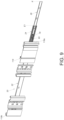
FIG. 1 is a schematic diagram of a slide rail assembly in an extended state according to an embodiment of the present invention, -
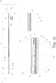
FIG. 2 is an exploded diagram of the slide rail assembly according to the embodiment of the present invention, -
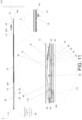
FIG. 3 is a partial diagram of the slide rail assembly as an operating member is located at a first operating position according to the embodiment of the present invention, -
FIG. 4 is an enlarged diagram of an A portion of the slide rail assembly as shown inFIG. 3 according to the embodiment of the present invention, -
FIG. 5 is another partial diagram of the slide rail assembly as the operating member is located at the first operating position according to the embodiment of the present invention, -
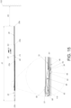
FIG. 6 is a partial diagram of the slide rail assembly as the operating member is located at a second operating position according to the embodiment of the present invention, -
FIG. 7 is an enlarged diagram of a B portion of the slide rail assembly as shown inFIG. 6 according to the embodiment of the present invention, -
FIG. 8 is another partial diagram of the slide rail assembly as the operating member is located at the second operating position according to the embodiment of the present invention, -
FIG. 9 is a diagram of the slide rail assembly adapted for a rack according to the embodiment of the present invention, -
FIG. 10 is a diagram of the slide rail assembly as the second rail and the operating member are respectively located at a first extended position and the first operating position according to the embodiment of the present invention, -
FIG. 11 is a diagram of the slide rail assembly as the second rail and the operating member are respectively located at the first extended position and the second operating position according to the embodiment of the present invention, -
FIG. 12 is a diagram of the slide rail assembly as the second rail displaces relative to the first rail away from the first extended position toward a retracted position along a retracting direction according to the embodiment of the present invention, -
FIG. 13 is a diagram of the slide rail assembly as the second rail is located at the retracted position according to the embodiment of the present invention, -
FIG. 14 is a diagram of the slide rail assembly as the second rail displaces relative to the first rail away from the retracted position along an opening direction according to the embodiment of the present invention, -
FIG. 15 is a diagram of the slide rail assembly as the second rail and the operating member are respectively located at a second extended position and the first operating position according to the embodiment of the present invention, -
FIG. 16 is a diagram of the slide rail assembly as a third rail is detached from the second rail located at the second extended position according to the embodiment of the present invention, -
FIG. 17 is a diagram of the slide rail assembly as the blocking member and the positioning member have not been driven to move away from the first state by the third rail displacing relative to the second rail along the retracting direction according to the embodiment of the present invention, -
FIG. 18 is a diagram of the slide rail assembly as the blocking member and the positioning member are driven to move from the first state to the second state by the third rail displacing relative to the second rail along the retracting direction according to the embodiment of the present invention, -
FIG. 19 is another diagram of the slide rail assembly as the second rail and the operating member are respectively located at the second extended position and the first operating position according to the embodiment of the present invention, and -
FIG. 20 is a diagram of the slide rail assembly as the second rail and the operating member are respectively located at the second extended position and the second operating position according to the embodiment of the present invention. - In the following detailed description of the preferred embodiments, reference is made to the accompanying drawings which form a part hereof, and in which is shown by way of illustration specific embodiments in which the invention may be practiced. In this regard, directional terminology, such as "top", "bottom", "left", "right", "front", "back", etc., is used with reference to the orientation of the Figure(s) being described. The members of the present invention can be positioned in a number of different orientations. As such, the directional terminology is used for purposes of illustration and is in no way limiting. Accordingly, the drawings and descriptions will be regarded as illustrative in nature and not as restrictive. Also, if not specified, the term "connect" is intended to mean either an indirect or direct mechanical connection. Thus, if a first device is connected to a second device, that connection may be through a direct mechanical connection, or through an indirect mechanical connection via other devices and connections.
- As shown in
FIG. 1 andFIG. 2 , aslide rail assembly 20 includes afirst rail 22 and asecond rail 24. Preferably, theslide rail assembly 20 further includes athird rail 26. Thesecond rail 24 is movably mounted between thefirst rail 22 and thethird rail 26. In this embodiment, by way of example, thefirst rail 22, thesecond rail 24 and thethird rail 26 can be an outer rail, a middle rail and an inner rail, respectively, and thefirst rail 22, thesecond rail 24 and thethird rail 26 can displace relative to one another along a longitudinal direction. As shown inFIG. 1 , when theslide rail assembly 20 is in an extended state, e.g., a fully extended state, thesecond rail 24 is located at a first extended position E1 relative to thefirst rail 22, and thethird rail 26 is located at an opened position K relative to thesecond rail 24. - In this embodiment, by way of example, the longitudinal direction can be defined by a length direction or a displacing direction of the
first rail 22, thesecond rail 24 or thethird rail 26, and parallel to an X axis. A transverse direction can be defined by a lateral direction or a width direction of thefirst rail 22, thesecond rail 24 or thethird rail 26, and parallel to a Y axis. A vertical direction can be defined by a height direction of thefirst rail 22, thesecond rail 24 or thethird rail 26, and parallel to a Z axis. - The
first rail 22 includes afirst wall 28a, asecond wall 28b and alongitudinal wall 30 connected between thefirst wall 28a and thesecond wall 28b of thefirst rail 22. Thefirst wall 28a, thesecond wall 28b and thelongitudinal wall 30 of thefirst rail 22 cooperatively define a first channel of thefirst rail 22 configured to at least partially accommodate thesecond rail 24. As shown inFIG. 2 , a blockingfeature 32 is arranged on thefirst rail 22. Preferably, apositioning feature 36 and a releasingfeature 38 are further arranged on thefirst rail 22. The blockingfeature 32, thepositioning feature 36 and the releasingfeature 38 are sequentially arranged on thelongitudinal wall 30 of thefirst rail 22 along the longitudinal direction from front to back. - Preferably, the
first rail 22 includes afront end portion 22a and arear end portion 22b. The releasingfeature 38 is more adjacent to therear end portion 22b of thefirst rail 22 than the blockingfeature 32 and thepositioning feature 36. The blockingfeature 32 is more adjacent to thefront end portion 22a of thefirst rail 22 than thepositioning feature 36 and the releasingfeature 38. - Preferably, the
slide rail assembly 20 further includes apredetermined structure 40 arranged on thelongitudinal wall 30 of thefirst rail 22. Thepredetermined structure 40 includes the blockingfeature 32, alongitudinal portion 42 and a guidingportion 44. Thelongitudinal portion 42 is located between the blockingfeature 32 and the guidingportion 44. In this embodiment, by way of example, the blockingfeature 32 can be a blocking wall or an erecting wall, and the guidingportion 44 can be an inclined surface or an arc surface. However, the present invention is not limited to this embodiment. - Preferably, in this embodiment, by way of example, the releasing
feature 38 can be a protrusion protruding from thelongitudinal wall 30 of thefirst rail 22 along the transverse direction or the lateral direction of thefirst rail 22 and includes a guidingsection 45, and the guidingsection 45 can be an inclined surface or an arc surface. However, the present invention is not limited to this embodiment. - Preferably, the
first rail 22 further includes a firstauxiliary portion 46 and a secondauxiliary portion 48. Thepositioning feature 36 is defined between the firstauxiliary portion 46 and the secondauxiliary portion 48. The firstauxiliary portion 46 and the secondauxiliary portion 48 are spaced apart from each other. In this embodiment, by way of example, the firstauxiliary portion 46 can be a protrusion protruding from thelongitudinal wall 30 of thefirst rail 22 along the transverse direction or the lateral direction of thefirst rail 22, and the firstauxiliary portion 46 and the secondauxiliary portion 48 can be substantially symmetrical structures. - Preferably, the first
auxiliary portion 46 and the secondauxiliary portion 48 include afirst guiding structure 50 and asecond guiding structure 52, respectively. Thefirst guiding structure 50 is configured to guide the positioningmember 62 to pass over the firstauxiliary portion 46. Thesecond guiding structure 52 is configured to guide the positioningmember 62 to pass over the secondauxiliary portion 48. In this embodiment, by way of example, thefirst guiding structure 50 and thesecond guiding structure 52 can be inclined surfaces or arc surfaces. However, the present invention is not limited to this embodiment. - The
second rail 24 includes afirst wall 54a, asecond wall 54b and alongitudinal wall 56 connected between thefirst wall 54a and thesecond wall 54b of thesecond rail 24. Thefirst wall 54a, thesecond wall 54b and thelongitudinal wall 56 of thesecond rail 24 cooperatively define a second channel of thesecond rail 24 configured to at least partially accommodate thethird rail 26. Thelongitudinal wall 56 of thesecond rail 24 includes a first side L1 and a second side L2 opposite to the first side L1. The first side L1 and the second side L2 of thelongitudinal wall 56 of thesecond rail 24 are adjacent to thefirst rail 22 and thethird rail 26, respectively. - The
slide rail assembly 20 further includes anauxiliary member 57, a blockingmember 58 and an operatingmember 60. Preferably, theslide rail assembly 20 further includes a positioningmember 62 and a recoveringresilient member 64. The blockingmember 58 and the positioningmember 62 are movably mounted on thesecond rail 24. In this embodiment, the blockingmember 58 and the positioningmember 62 can be pivotally connected to the second side L2 of thelongitudinal wall 56 of thesecond rail 24 by a pivotingshaft 66, and an extending direction of the pivotingshaft 66 is parallel to the height direction or the vertical direction of thesecond rail 24, i.e., the blockingmember 58 and the positioningmember 62 are configured to pivot relative to thelongitudinal wall 56 of thesecond rail 24 laterally or transversely. - Preferably, the
second rail 24 includes at least one hole communicated between the first side L1 of thelongitudinal wall 56 of thesecond rail 24 and the second side L2 of thelongitudinal wall 56 of thesecond rail 24. In this embodiment, by way of example, thesecond rail 24 includes a first hole H1 and a second hole H2. Furthermore, theauxiliary member 57 is arranged on thesecond rail 24 and configured to cooperate with the operatingmember 60. The blockingmember 58 includes a blockingportion 68 extending through the first hole H1 toward thelongitudinal wall 30 of thefirst rail 22, and the blockingportion 68 of the blockingmember 58 is configured to cooperate with the blockingfeature 32 on thefirst rail 22. In addition, the positioningmember 62 includes apositioning portion 70 extending through the second hole H2 toward thelongitudinal wall 30 of thefirst rail 22, and thepositioning portion 70 of the positioningmember 62 is configured to cooperate with thepositioning feature 36 on thefirst rail 22. - Preferably, the
slide rail assembly 20 further includes apredetermined object 72 connected to thelongitudinal wall 56 of thesecond rail 24. Thepredetermined object 72 includes a firstresilient feature 74 and a secondresilient feature 76 configured to provide a first resilient force and a second resilient force to the blockingmember 58 and the positioningmember 62, respectively. In this embodiment, by way of example, thepredetermined object 72 can be a resilient clip or any other resilient member, and the firstresilient feature 74 and the secondresilient feature 76 can be two arm portions of thepredetermined object 72. However, the present invention is not limited to this embodiment. - The operating
member 60 is movably mounted on thesecond rail 24 and configured to operate one of the blockingmember 58 and the positioningmember 62. - Preferably, the operating
member 60 is arranged on thelongitudinal wall 56 of thesecond rail 24, and the operatingmember 60 includes an operatingportion 78, a drivingportion 80 and an extendingportion 82 connected between the operatingportion 78 and the drivingportion 80. Thesecond rail 24 includes afront end portion 24a and arear end portion 24b. The operatingportion 78 is located adjacent to thefront end portion 24a of thesecond rail 24. - Preferably, the operating
portion 78 and the drivingportion 80 are located adjacent to afront end 82a and arear end 82b of the extendingportion 82, respectively. - Preferably, the
second rail 24 includes a throughhole 81 communicated between the first side L1 of thelongitudinal wall 56 of thesecond rail 24 and the second side L2 of thelongitudinal wall 56 of thesecond rail 24. The operatingportion 78 includes acorresponding space 83 located at a position corresponding to the throughhole 81. A size of the throughhole 81 is greater than a size of thecorresponding space 83. In this embodiment, by way of example, the correspondingspace 83 can be a recessed structure or a hollow structure configured to allow an insertion of a user's finger therein for easy operation of the operatingmember 60. However, the present invention is not limited to this embodiment. - Preferably, the driving
portion 80 is located adjacent to the blockingmember 58 and the positioningmember 62. - Preferably, the
slide rail assembly 20 further includes at least one mounting feature and at least one connecting feature configured to cooperate with the at least one mounting feature for allowing the operatingmember 60 to move relative to thesecond rail 24 within a limited range along the longitudinal direction. In this embodiment, by way of example, a first connectingfeature 86a and a second connectingfeature 86b can be two longitudinal holes arranged on the operatingmember 60 and thesecond rail 24, respectively, and afirst mounting feature 84a and asecond mounting feature 84b can be two protruding pins arranged on thesecond rail 24 and the operatingmember 60, respectively, and passing through the first connectingfeature 86a and the second connectingfeature 86b, respectively. However, the present invention is not limited to this embodiment. - The recovering
resilient member 64 is configured to provide a recovering resilient force F' to the operatingmember 60. As shown inFIG. 1 , in this embodiment, by way of example, two ends of the recoveringresilient member 64 are connected to a firstpredetermined section 55 of the operatingmember 60 and a secondpredetermined section 77 of thesecond rail 24, respectively. However, the present invention is not limited to this embodiment. - Preferably, as shown in
FIG. 4 , the operatingmember 60 includes anengaging feature 88. In this embodiment, by way of example, the engagingfeature 88 is arranged on the drivingportion 80. However, the present invention is not limited to this embodiment. - Preferably, as shown in
FIG. 4 , in this embodiment, by way of example, the engagingfeature 88 can be a hook portion and include afirst guiding surface 96, e.g., an inclined surface or an arc surface. - As shown in
FIG. 3 to FIG. 5 , the blockingmember 58 and the positioningmember 62 are located adjacent to therear end portion 24b of thesecond rail 24. The drivingportion 80 and the extendingportion 82 of the operatingmember 60 are located adjacent to the second side L2 and the first side L1 of thelongitudinal wall 56 of thesecond rail 24, respectively. As shown inFIG. 3 to FIG. 5 , in this embodiment, by way of example, the drivingportion 80 of the operatingmember 60 can be an independent member located adjacent to the second side L2 of thelongitudinal wall 56 of thesecond rail 24 and fixedly connected to therear end 82b of the extendingportion 82 of the operatingmember 60 located adjacent to the first side L1 of thelongitudinal wall 56 of thesecond rail 24, by a fixingmember 97 extending from the second side L2 of thelongitudinal wall 56 of thesecond rail 24 to the first side L1 of thelongitudinal wall 56 of thesecond rail 24 through a restraininghole 95. However, the present invention is not limited to this embodiment. Besides, as shown inFIG. 4 , the blockingmember 58 and the positioningmember 62 are both configured to be in a first state S1 relative to thesecond rail 24, and the operatingmember 60 is configured to be located at a first operating position P1 relative to thesecond rail 24. - Specifically, as shown in
FIG. 4 andFIG. 5 , theauxiliary member 57 includes aresilient arm 98 and apredetermined portion 100 arranged on theresilient arm 98. Preferably, as shown inFIG. 4 andFIG. 5 , theauxiliary member 57 further includes a mountingportion 102 connected to the first side L1 of thelongitudinal wall 56 of thesecond rail 24. Theresilient arm 98 extends from the mountingportion 102. Thepredetermined portion 100 extends from the first side L1 of thelongitudinal wall 56 of thesecond rail 24 to the second side L2 of thelongitudinal wall 56 of thesecond rail 24 through apredetermined hole 104 of thesecond rail 24. Thepredetermined portion 100 is configured to cooperate with theengaging feature 88 of the operatingmember 60. - Preferably, the
predetermined portion 100 includes asecond guiding surface 106, e.g., an inclined surface or an arc surface, located at a position corresponding to the first guidingsurface 96 of theengaging feature 88. - Preferably, the blocking
member 58 further includes an abuttingportion 108, and the pivotingshaft 66 is located between the blockingportion 68 and the abuttingportion 108 of the blockingmember 58. As shown inFIG. 4 , the abuttingportion 108 is located at a position corresponding to afirst driving section 110 of the drivingportion 80 of the operatingmember 60 and for abutting against thefirst driving section 110 of the drivingportion 80 of the operatingmember 60. As shown inFIG. 4 , the firstresilient feature 74 is configured to provide the first resilient force to the blockingmember 58, e.g., the blockingportion 68 of the blockingmember 58, for retaining the blockingmember 58 in the first state S1, i.e., biasing the blockingportion 68 of the blockingmember 58 to move toward thelongitudinal wall 30 of thefirst rail 22. - Preferably, the positioning
member 62 further includes anabutting section 112, and the pivotingshaft 66 is located between the positioningportion 70 and theabutting section 112 of the positioningmember 62. As shown inFIG. 4 , the abuttingsection 112 is located at a position corresponding to asecond driving section 114 of the drivingportion 80 of the operatingmember 60 and for abutting against thesecond driving section 114 of the drivingportion 80 of the operatingmember 60. Thesecond driving section 114 and thefirst driving section 110 are located at positions corresponding to each other and have substantially identical structures. As shown inFIG. 4 , the secondresilient feature 76 is configured to provide the second resilient force to the positioningmember 62, e.g., the positioningportion 70 of the positioningmember 62, for retaining the positioningmember 62 in the first state S1, i.e., biasing thepositioning portion 70 of the positioningmember 62 to move toward thelongitudinal wall 30 of thefirst rail 22. - Preferably, one of the abutting
portion 108 of the blockingmember 58 and thefirst driving section 110 of the operatingmember 60 includes a guiding feature, e.g., an inclined surface or an arc surface, for facilitating the operatingmember 60 to drive the blockingmember 58 by a cooperation of thefirst driving section 110 and the abuttingportion 108. Similarly, one of theabutting section 112 of the positioningmember 62 and thesecond driving section 114 of the operatingmember 60 includes another guiding feature, e.g., an inclined surface or an arc surface, for facilitating the operatingmember 60 to drive the positioningmember 62 by a cooperation of thesecond driving section 114 and theabutting section 112. - As shown in
FIG. 6 to FIG. 8 , when the operatingmember 60, e.g., the operatingportion 78 of the operatingmember 60, is operated by an external force F along an opening direction D1 to move relative to thesecond rail 24 along the opening direction D1 from the first operating position P1 to a second operating position P2, the operatingmember 60 drives the blockingmember 58 and the positioningmember 62 to move, e.g., pivot laterally or transversely, from the first state S1 to the second state S2 by thefirst driving section 110 and thesecond driving section 114 of the drivingportion 80, respectively, so as to move the blockingportion 68 of the blockingmember 58 and thepositioning portion 70 of the positioningmember 62 away from thefirst rail 22, e.g., thelongitudinal wall 30 of thefirst rail 22, by overcoming the first resilient force provided by the firstresilient feature 74 and the second resilient force provided by the secondresilient feature 76, respectively. - As shown in
FIG. 7 andFIG. 8 , when the operatingmember 60 is located at the second operating position P2, the recoveringresilient member 64 is resiliently deformed to generate the recovering resilient force F', and theengaging feature 88 of the operatingmember 60 engages with thepredetermined portion 100 of theauxiliary member 57 for retaining the operatingmember 60 at the second operating position P2. - Preferably, when the operating
member 60 moves from the first operating position P1 as shown inFIG. 4 to the second operating position P2 as shown inFIG. 7 , the first guidingsurface 96 of theengaging feature 88 abuts against thesecond guiding surface 106 of thepredetermined portion 100 for guiding theengaging feature 88 to engage with ablocking section 115 of thepredetermined portion 100. - Preferably, as shown in
FIG. 7 , when the operatingmember 60 is located at the second operating position P2, thefirst driving section 110 and thesecond driving section 114 of the operatingmember 60 keep pressing theabutting portion 108 of the blockingmember 58 and theabutting section 112 of the positioningmember 62, respectively, so as to retain the blockingmember 58 and the positioningmember 62 at the second state S2. - As shown in
FIG. 9 , theslide rail assembly 20 is mounted on arack 116 and in the fully extended state. Thefirst rail 22 is configured to be mounted, e.g., fixed, to therack 116. Thethird rail 26 is configured to support a carried object, which is not shown in the figure. In such a way, the carried object can move into or out of therack 116 by theslide rail assembly 20. Therack 116 includes a front end 116a and arear end 116b. The operatingportion 78 protrudes forwardly beyond the front end 116a of therack 116 for easy operation. - As shown in
FIG. 10 , theslide rail assembly 20 is in the fully extended state. Thesecond rail 24 is located at the first extended position E1 relative to thefirst rail 22, and thethird rail 26 is located at the opening position K relative to thesecond rail 24. It should be noticed that, when thesecond rail 24 and thethird rail 26 are located at the first extended position E1 relative to thefirst rail 22 and at the opening position K relative to thesecond rail 24, respectively, theslide rail assembly 20 has a first length J1, and a first distance X1 is formed between afront end portion 26a of thethird rail 26 and anobject 122. However, the first distance X1 is too narrow or short to detach thethird rail 26 from thesecond rail 24 along the opening direction D1. Besides, as shown inFIG. 10 , when thesecond rail 24 is located at the first extended position E1 relative to thefirst rail 22, the blockingfeature 32 blocks the blockingportion 68 of the blockingmember 58 in the first state S1 for preventing thesecond rail 24 from displacing relative to thefirst rail 22 away from the first extended position E1 along a retracting direction D2, and thepositioning portion 70 of the positioningmember 62 in the first state S1 abuts against thelongitudinal wall 30 of thefirst rail 22. Furthermore, at this moment, the operatingmember 60 is located at the first operating position P1. Therefore, the recoveringresilient member 64 and theengaging feature 88 of the operatingmember 60 are in states as shown inFIG. 3 to FIG. 5 , i.e., the recoveringresilient member 64 is not resiliently deformed, and theengaging feature 88 of the operatingmember 60 does not engage with thepredetermined portion 100 of theauxiliary member 57. - As shown in
FIG. 10 andFIG. 11 , when the operatingportion 78 of the operatingmember 60 is operated by the external force F along the opening direction D1 to move relative to thesecond rail 24 along the opening direction D1 from the first operating position P1 to the second operating position P2, the operatingmember 60 drives the blockingmember 58 and the positioningmember 62 to move from the first state S1 to the second state S2 by thefirst driving section 110 and thesecond driving section 114 of the drivingportion 80, respectively. When the blockingmember 58 is in the second state S2, the blockingportion 68 of the blockingmember 58 is moved away from thelongitudinal wall 30 of thefirst rail 22 laterally or transversely. Therefore, the firstresilient feature 74 is resiliently deformed by the blockingmember 58 in the second state S2, and the blockingfeature 32 does not block the blockingportion 68 of the blockingmember 58 in the second state S2 for allowing thesecond rail 24 to displace relative to thefirst rail 22 away from the first extended position E1 along the retracting direction D2. When the positioningmember 62 is in the second state S2, the positioningportion 70 of the positioningmember 62 is moved away from thelongitudinal wall 30 of thefirst rail 22 laterally or transversely. Therefore, the secondresilient feature 76 is resiliently deformed by the positioningmember 62 in the second state S2, and thepositioning portion 70 of the positioningmember 62 is misaligned with thepositioning feature 36 along the longitudinal direction. - When the operating
member 60 is located at the second operating position P2 as shown inFIG. 12 , the recoveringresilient member 64 and theengaging feature 88 of the operatingmember 60 are in states as shown inFIG. 7 andFIG. 8 , i.e., the recoveringresilient member 64 is resiliently deformed for generating the recovering resilient force F' along the retracting direction D2, and theengaging feature 88 of the operatingmember 60 engages with theblocking section 115 of thepredetermined portion 100 of theauxiliary member 57 for retaining the operatingmember 60 at the second operating position P2. - As shown in
FIG. 12 andFIG. 13 , when theengaging feature 88 of the operatingmember 60 disengages from thepredetermined portion 100 of theauxiliary member 57, the operatingmember 60 moves from the second operating position P2 to the first operating position P1 in response to the recovering resilient force F' provided by the recoveringresilient member 64. Furthermore, as shown inFIG. 12 , when thesecond rail 24 displaces relative to thefirst rail 22 along the retracting direction D2 from the first extended position E1 to a retracted position R, the positioningportion 70 of the positioningmember 62 in the second state S2 is misaligned with thepositioning feature 36 along the longitudinal direction, such that the positioningmember 62 can pass over thepositioning feature 36 along the retracting direction D2 without any obstruction, i.e., the positioningportion 70 of the positioningmember 62 is prevented from being engaged with thepositioning feature 36. Besides, when thesecond rail 24 displaces along the retracting direction D2 from a position as shown inFIG. 12 to a position as shown inFIG. 13 , thesecond guiding surface 106 of thepredetermined portion 100 of theauxiliary member 57 abuts against the guidingsection 45 of the releasingfeature 38 on thefirst rail 22, such that theresilient arm 98 of theauxiliary member 57 moves along a predetermined direction U for disengaging theengaging feature 88 of the operatingmember 60 from theblocking section 115 of thepredetermined portion 100 of theauxiliary member 57, so as to allow the operatingmember 60 to move from the second operating position P2 as shown inFIG. 12 to the first operating position P1 as shown inFIG. 13 along the retracting direction D2 in response to the recovering resilient force F' provided by the recoveringresilient member 64. Besides, when the operatingmember 60 is located at the first operating position P1 as shown inFIG. 13 , the blockingmember 58 and the positioningmember 62 are in states as shown inFIG. 4 , i.e., the blockingmember 58 and the positioningmember 62 move from the second state S2 to the first state S1 in response to the first resilient force provided by the firstresilient feature 74 and the second resilient force provided by the secondresilient feature 76, respectively. - Preferably, the
first rail 22 further includes at least oneblocking structure 124. In this embodiment, by way of example, the blockingstructure 124 can be a protrusion. However, the present invention is not limited to this embodiment. As shown inFIG. 13 , when thesecond rail 24 is located at the retracted position R relative to thefirst rail 22, the blockingstructure 124 is configured to block therear end portion 24b of thesecond rail 24 for preventing thesecond rail 24 from displacing away from the retracted position R along the retracting direction D2. In other words, the retracted position R can be a fully retracted position. - As shown in
FIG. 14 andFIG. 15 , when thesecond rail 24 displaces relative to thefirst rail 22 from the retracted position R to a second extended position E2 along the opening direction D1, thepositioning feature 36 is configured to engage with the positioningmember 62 in the first state S1 for preventing thesecond rail 24 from displacing relative to thefirst rail 22 away from the second extended position E2 along the retracting direction D2 or theopening direction D 1. - Furthermore, when the
second rail 24 displaces relative to thefirst rail 22 from the retracted position R to the second extended position E2 along the opening direction D1, the positioningportion 70 of the positioningmember 62 abuts against thesecond guiding structure 52 of the secondauxiliary portion 48 to guide the positioningmember 62 to move away from the first state to pass over the secondauxiliary portion 48, and then the positioningmember 62 moves back to the first state to engage thepositioning portion 70 of the positioningmember 62 with thepositioning feature 36 in response to the second resilient force provided by the secondresilient feature 76. When thepositioning portion 70 of the positioningmember 62 in the first state S1 engages with thepositioning feature 36, the positioningportion 70 of the positioningmember 62 is blocked between the firstauxiliary portion 46 and the secondauxiliary portion 48 for preventing thesecond rail 24 from displacing relative to thefirst rail 22 away from the second extended position E2 along the retracting direction D2 or theopening direction D 1. - As shown in
FIG. 15 andFIG. 16 , when thesecond rail 24 is located at the second extended position E2 relative to thefirst rail 22, theslide rail assembly 20 has a second length J2 less than the first length J1, and a second distance X2 is formed between thefront end portion 26a of thethird rail 26 and theobject 122 and greater than the first distance X1, which facilitates thethird rail 26 to be detached from thesecond rail 24 along the opening direction D1. - As shown in
FIG. 17 andFIG. 18 , when it is desired to displace thesecond rail 24 relative to thefirst rail 22 from the second extended position E2 to the retracted position R along the retracting direction D2 or to the first extended position E1 along the opening direction D1, thethird rail 26 can be operated to displace, e.g., away from the opening position K, along the retracting direction D2 to abut against the abuttingsection 112 of the positioningmember 62, e.g., by arear end portion 26b of thethird rail 26, to move the positioningmember 62 away from the first state S1 for disengaging thepositioning portion 70 of the positioningmember 62 from thepositioning feature 36, so as to allow thesecond rail 24 to displace relative to thefirst rail 22 from the second extended position E2 to the retracted position R along the retracting direction D2 or to the first extended position E1 along the opening direction D1. - Preferably, during the aforementioned displacement of the
third rail 26 along the retracting direction D2, thethird rail 26 or a predetermined feature, e.g., a protrusion, on thethird rail 26 abuts against the abuttingportion 108 of the blockingmember 58 to move the blockingmember 58 away from the first state S1. - Besides, as shown in
FIG. 19 andFIG. 20 , when thesecond rail 24 is located at the second extended position E2 relative to thefirst rail 22, the positioningmember 62 can be driven to move away from the first state S1 not only by thethird rail 26 displacing along the retracting direction D2, as mentioned above, but also by the operatingmember 60 moving from the first operating position P1 to the second operating position P2. Specifically, when thesecond rail 24 is located at the second extended position E2 relative to thefirst rail 22, the operatingmember 60 can be operated to move from the first operating position P1 to the second operating position P2 along the opening direction D1 to drive the positioningmember 62 to move from the first state S1 to the second state S2 by thesecond driving section 114 for disengaging thepositioning portion 70 of the positioningmember 62 from thepositioning feature 36 to allow thesecond rail 24 to displace relative to thefirst rail 22 from the second extended position E2 to the retracted position R along the retracting direction D2 or to the first extended position E1 along the opening direction D1. Furthermore, when the operatingmember 60 is located at the second operating position P2, the engagingfeature 88 engages with thepredetermined portion 100 of theauxiliary member 57 for retaining the operatingmember 60 at the second operating position P2. - In contrast to the prior art, the present invention has following characteristics.
- 1. The operating
member 60 can be retained at the second operating position P2 when theengaging feature 88 engages with thepredetermined portion 100, and the operatingmember 60 can be released to move from the second operating position P2 to the first operating position P1 in response to the recovering resilient force F' provided by the recoveringresilient member 64 when theengaging feature 88 disengages from thepredetermined portion 100. Besides, a moving direction of the operatingmember 60 from the first operating position P1 to the second operating position P2 is the same as the opening direction D1, so as to achieve more intuitive operation of the operatingmember 60 from the first operating position P1 to the second operating position P2. - 2. The blocking
member 58 and the positioningmember 62 share thesame pivoting shaft 66, and the extending direction of the pivotingshaft 66 is parallel to the height direction or the vertical direction, i.e., the blockingmember 58 and the positioningmember 62 are configured to pivot relative to thelongitudinal wall 56 of thesecond rail 24 laterally or transversely. Such configuration can prevent any close contact in a blocking relation between the blockingportion 68 of the blockingmember 58 and the blockingfeature 32 and a blocking relation between the positioningportion 70 of the positioningmember 62 and thepositioning feature 36, so as to have advantages of less resistive forces and labor saving. - Those skilled in the art will readily observe that numerous modifications and alterations of the device and method may be made while retaining the teachings of the invention. Accordingly, the above disclosure should be construed as limited only by the metes and bounds of the appended claims.
Claims (15)
- A slide rail assembly (20) comprising:a first rail (22);a blocking feature (32) arranged on the first rail (22); anda second rail (24) displaceable relative to the first rail (22);characterized by:an auxiliary member (57) arranged on the second rail (24), the auxiliary member (57) comprising a resilient arm (98) and a predetermined portion (100) arranged on the resilient arm (98);a pivoting shaft (66);a blocking member (58) pivotally connected to the second rail (24) by the pivoting shaft (66), the blocking member (58) being movably switchable between a first state (S1) and a second state (S2) relative to the second rail (24), the blocking member (58) comprising a blocking portion (68) and an abutting portion (108), the pivoting shaft (66) being located between the blocking portion (68) and the abutting portion (108); andan operating member (60) configured to operate the blocking member (58), and the operating member (60) comprising an engaging feature (88);wherein when the second rail (24) is located at a first extended position (E1) relative to the first rail (22), the blocking feature (32) blocks the blocking portion (68) of the blocking member (58) in the first state (S1) for preventing the second rail (24) from displacing away from the first extended position (E1) toward a retracted position (R) along a retracting direction (D2);wherein when the operating member (60) moves from a first operating position (P1) to a second operating position (P2), the abutting portion (108) of the blocking member (58) is driven by the operating member (60) to switch the blocking member (58) from the first state (S1) to the second state (S2), such that the blocking feature (32) does not block the blocking portion (68) of the blocking member (58) in the second state (S2) for allowing the second rail (24) to displace relative to the first rail (22) away from the first extended position (E1) toward the retracted position (R) along the retracting direction (D2);wherein when the operating member (60) is located at the second operating position (P2), the engaging feature (88) engages with the predetermined portion (100) of the auxiliary member (57) to retain the operating member (60) at the second operating position (P2).
- The slide rail assembly (20) of claim 1, characterized in that the operating member (60) is movably mounted on the second rail (24), and when the operating member (60) is located at the second operating position (P2), the operating member (60) is configured to retain the blocking member (58) in the second state (S2).
- The slide rail assembly (20) of any of claims 1 to 2, further characterized by a positioning member (62) movably mounted on the second rail (24) and switchable between a first state (S1) and a second state (S2) relative to the second rail (24), and when the operating member (60) is located at the second operating position (P2), the operating member (60) being configured to retain the positioning member (62) in the second state (S2).
- The slide rail assembly (20) of claim 3, characterized in that the auxiliary member (57) further comprises a mounting portion (102) connected to the second rail (24), and the resilient arm (98) extends from the mounting portion (102).
- The slide rail assembly (20) of any of claims 3 to 4, further characterized by a recovering resilient member (64), and when the engaging feature (88) disengages from the predetermined portion (100) of the auxiliary member (57), the operating member (60) moving from the second operating position (P2) to the first operating position (P1) in response to a recovering resilient force (F') provided by the recovering resilient member (64).
- The slide rail assembly (20) of claim 5, further characterized by a first resilient feature (74), and when the operating member (60) is located at the first operating position (P1), the blocking member (58) moving from the second state (S2) to the first state (S1) in response to a first resilient force provided by the first resilient feature (74).
- The slide rail assembly (20) of claim 6, further characterized by a second resilient feature (76), and when the operating member (60) is located at the first operating position (P1), the positioning member (62) moving from the second state (S2) to the first state (S1) in response to a second resilient force provided by the second resilient feature (76).
- The slide rail assembly (20) of claim 7, further characterized by a predetermined object (72) connected to the second rail (24), and the predetermined object (72) comprising the first resilient feature (74) and the second resilient feature (76).
- The slide rail assembly (20) of any of claims 1 to 8, further characterized by a releasing feature (38) arranged on the first rail (22), and when the second rail (24) displaces from the first extended position (E1) to the retracted position (R) along the retracting direction (D2), the resilient arm (98) of the auxiliary member (57) being driven by the releasing feature (38) to disengage the engaging feature (88) from the predetermined portion (100) of the auxiliary member (57).
- The slide rail assembly (20) of any of claims 1 to 9, further characterized by a positioning feature (36) arranged on the first rail (22), and when the second rail (24) displaces relative to the first rail (22) from the retracted position (R) to a second extended position (E2) along an opening direction (D1), the positioning member (62) in the first state (S1) engaging with the positioning feature (36) for preventing the second rail (24) from displacing relative to the first rail (22) away from the second extended position (E2) along the retracting direction (D2).
- The slide rail assembly (20) of claim 10, characterized in that when the second rail (24) is located at the first extended position (E1), the slide rail assembly (20) has a first length (L1), and when the second rail (24) is located at the second extended position (E2), the slide rail assembly (20) has a second length (L2) less than the first length (L1).
- The slide rail assembly (20) of any of claims 10 to 11, further characterized by a third rail (26), the second rail (24) being movably mounted between the first rail (22) and the third rail (26), and when the second rail (24) is located at the second extended position (E2), the third rail (26) displacing relative to the second rail (24) away from an opened position (K) along the retracting direction (D2) driving the positioning member (62) to move away from the first state (S1) to disengage the positioning member (62) from the positioning feature (36) for allowing the second rail (24) to displace relative to the first rail (22) away from the second extended position (E2) along the retracting direction (D2).
- The slide rail assembly (20) of any of claims 10 to 12, characterized in that when the second rail (24) is located at the second extended position (E2), the operating member (60) moving from the first operating position (P1) to the second operating position (P2) drives the positioning member (62) to move away from the first state (S 1) to disengage the positioning member (62) from the positioning feature (36) for allowing the second rail (24) to displace relative to the first rail (22) away from the second extended position (E2) along the retracting direction (D2), and when the operating member (60) is located at the second operating position (P2), the engaging feature (88) engages with the predetermined portion (100) of the auxiliary member (57) to retain the operating member (60) at the second operating position (P2).
- The slide rail assembly (20) of any of claims 3 to 13, characterized in that the blocking member (58) and the positioning member (62) are pivotally connected to the second rail (24) by the pivoting shaft (66), an extending direction of the pivoting shaft (66) is parallel to a height direction of a longitudinal wall (56) of the second rail (24), and the blocking member (58) and the positioning member (62) are configured to pivot relative to the longitudinal wall (56) of the second rail (24) laterally.
- The slide rail assembly (20) of any of claims 1 to 13, characterized in that an extending direction of the pivoting shaft (66) is parallel to a height direction of a longitudinal wall (56) of the second rail (24), and the blocking member (58) is configured to pivot relative to the longitudinal wall (56) of the second rail (24) laterally.
Applications Claiming Priority (1)
| Application Number | Priority Date | Filing Date | Title |
|---|---|---|---|
| TW112129647A TWI829614B (en) | 2023-08-04 | 2023-08-04 | Slide rail assembly |
Publications (2)
| Publication Number | Publication Date |
|---|---|
| EP4501174A1 true EP4501174A1 (en) | 2025-02-05 |
| EP4501174B1 EP4501174B1 (en) | 2025-09-10 |
Family
ID=89767645
Family Applications (1)
| Application Number | Title | Priority Date | Filing Date |
|---|---|---|---|
| EP24154139.0A Active EP4501174B1 (en) | 2023-08-04 | 2024-01-26 | Slide rail assembly |
Country Status (4)
| Country | Link |
|---|---|
| US (1) | US12378994B2 (en) |
| EP (1) | EP4501174B1 (en) |
| JP (1) | JP7772397B2 (en) |
| TW (1) | TWI829614B (en) |
Families Citing this family (2)
| Publication number | Priority date | Publication date | Assignee | Title |
|---|---|---|---|---|
| CN119453679B (en) * | 2023-08-08 | 2025-11-14 | 川湖科技股份有限公司 | slide rail assembly |
| TWI878119B (en) * | 2024-05-09 | 2025-03-21 | 川湖科技股份有限公司 | Rack mounting kit |
Citations (3)
| Publication number | Priority date | Publication date | Assignee | Title |
|---|---|---|---|---|
| US10041535B2 (en) | 2016-07-29 | 2018-08-07 | King Slide Works Co., Ltd. | Slide rail assembly |
| EP4018883A1 (en) * | 2020-12-22 | 2022-06-29 | King Slide Works Co., Ltd. | Slide rail assembly |
| EP4035568A1 (en) * | 2021-02-01 | 2022-08-03 | King Slide Works Co., Ltd. | Slide rail assembly |
Family Cites Families (7)
| Publication number | Priority date | Publication date | Assignee | Title |
|---|---|---|---|---|
| TWI601472B (en) * | 2015-04-13 | 2017-10-01 | King Slide Works Co Ltd | Slide rail assembly |
| TWI693044B (en) * | 2018-07-27 | 2020-05-11 | 川湖科技股份有限公司 | Slide rail assembly |
| TWI683638B (en) * | 2019-01-08 | 2020-02-01 | 川湖科技股份有限公司 | Slide rail assembly and rail kit thereof |
| TWI702019B (en) | 2019-05-06 | 2020-08-21 | 川湖科技股份有限公司 | Slide rail assembly |
| TWI704889B (en) | 2019-10-28 | 2020-09-21 | 川湖科技股份有限公司 | Slide rail assembly |
| TWI750987B (en) | 2020-12-30 | 2021-12-21 | 川湖科技股份有限公司 | Slide rail assembly |
| CN114847691B (en) * | 2021-02-04 | 2023-11-24 | 川湖科技股份有限公司 | Sliding rail assembly |
-
2023
- 2023-08-04 TW TW112129647A patent/TWI829614B/en active
-
2024
- 2024-01-11 US US18/409,821 patent/US12378994B2/en active Active
- 2024-01-26 EP EP24154139.0A patent/EP4501174B1/en active Active
- 2024-02-01 JP JP2024013798A patent/JP7772397B2/en active Active
Patent Citations (3)
| Publication number | Priority date | Publication date | Assignee | Title |
|---|---|---|---|---|
| US10041535B2 (en) | 2016-07-29 | 2018-08-07 | King Slide Works Co., Ltd. | Slide rail assembly |
| EP4018883A1 (en) * | 2020-12-22 | 2022-06-29 | King Slide Works Co., Ltd. | Slide rail assembly |
| EP4035568A1 (en) * | 2021-02-01 | 2022-08-03 | King Slide Works Co., Ltd. | Slide rail assembly |
Also Published As
| Publication number | Publication date |
|---|---|
| TWI829614B (en) | 2024-01-11 |
| EP4501174B1 (en) | 2025-09-10 |
| JP7772397B2 (en) | 2025-11-18 |
| TW202506037A (en) | 2025-02-16 |
| JP2025023790A (en) | 2025-02-17 |
| US20250043819A1 (en) | 2025-02-06 |
| US12378994B2 (en) | 2025-08-05 |
Similar Documents
| Publication | Publication Date | Title |
|---|---|---|
| EP4501174B1 (en) | Slide rail assembly | |
| EP3815575B1 (en) | Slide rail assembly | |
| EP3750445B1 (en) | Slide rail assembly and operation method thereof | |
| EP3750446A1 (en) | Slide rail assembly | |
| EP4023108B1 (en) | Slide rail assembly | |
| EP4477823A1 (en) | Interlock kit and related furniture assembly | |
| EP4393349B1 (en) | Slide rail assembly | |
| EP4327697A1 (en) | Slide rail assembly and slide rail kit | |
| EP4401520A1 (en) | Slide rail assembly | |
| EP4659626A1 (en) | Slide rail assembly | |
| EP4420560A1 (en) | Slide rail mechanism | |
| EP4631393A1 (en) | Slide rail assembly | |
| EP4461160A1 (en) | Furniture assembly | |
| EP4393348A1 (en) | Slide rail assembly | |
| EP4403732A1 (en) | Slide rail mechanism | |
| EP4456686A1 (en) | Slide rail assembly | |
| EP4480344A1 (en) | Slide rail assembly | |
| EP4529372A1 (en) | Slide rail assembly | |
| CN112754197B (en) | Slide rail assembly | |
| EP4648558A1 (en) | Rack mounting kit | |
| EP4736711A1 (en) | Slide rail assembly | |
| EP4523567A1 (en) | Slide rail assembly | |
| EP4635366B1 (en) | Slide rail assembly | |
| EP4656096A1 (en) | Slide rail assembly | |
| CN121058998A (en) | Sliding rail assembly |
Legal Events
| Date | Code | Title | Description |
|---|---|---|---|
| PUAI | Public reference made under article 153(3) epc to a published international application that has entered the european phase |
Free format text: ORIGINAL CODE: 0009012 |
|
| STAA | Information on the status of an ep patent application or granted ep patent |
Free format text: STATUS: REQUEST FOR EXAMINATION WAS MADE |
|
| 17P | Request for examination filed |
Effective date: 20241107 |
|
| AK | Designated contracting states |
Kind code of ref document: A1 Designated state(s): AL AT BE BG CH CY CZ DE DK EE ES FI FR GB GR HR HU IE IS IT LI LT LU LV MC ME MK MT NL NO PL PT RO RS SE SI SK SM TR |
|
| GRAP | Despatch of communication of intention to grant a patent |
Free format text: ORIGINAL CODE: EPIDOSNIGR1 |
|
| STAA | Information on the status of an ep patent application or granted ep patent |
Free format text: STATUS: GRANT OF PATENT IS INTENDED |
|
| INTG | Intention to grant announced |
Effective date: 20250502 |
|
| RIN1 | Information on inventor provided before grant (corrected) |
Inventor name: WANG, CHUN-CHIANG Inventor name: YU, KAI-WEN Inventor name: YANG, SHUN-HO Inventor name: CHEN, KEN-CHING |
|
| GRAS | Grant fee paid |
Free format text: ORIGINAL CODE: EPIDOSNIGR3 |
|
| GRAA | (expected) grant |
Free format text: ORIGINAL CODE: 0009210 |
|
| STAA | Information on the status of an ep patent application or granted ep patent |
Free format text: STATUS: THE PATENT HAS BEEN GRANTED |
|
| AK | Designated contracting states |
Kind code of ref document: B1 Designated state(s): AL AT BE BG CH CY CZ DE DK EE ES FI FR GB GR HR HU IE IS IT LI LT LU LV MC ME MK MT NL NO PL PT RO RS SE SI SK SM TR |
|
| REG | Reference to a national code |
Ref country code: GB Ref legal event code: FG4D |
|
| REG | Reference to a national code |
Ref country code: CH Ref legal event code: EP |
|
| REG | Reference to a national code |
Ref country code: DE Ref legal event code: R096 Ref document number: 602024000606 Country of ref document: DE |
|
| REG | Reference to a national code |
Ref country code: IE Ref legal event code: FG4D |
|
| PG25 | Lapsed in a contracting state [announced via postgrant information from national office to epo] |
Ref country code: NO Free format text: LAPSE BECAUSE OF FAILURE TO SUBMIT A TRANSLATION OF THE DESCRIPTION OR TO PAY THE FEE WITHIN THE PRESCRIBED TIME-LIMIT Effective date: 20251210 |
|
| REG | Reference to a national code |
Ref country code: LT Ref legal event code: MG9D |
|
| PG25 | Lapsed in a contracting state [announced via postgrant information from national office to epo] |
Ref country code: FI Free format text: LAPSE BECAUSE OF FAILURE TO SUBMIT A TRANSLATION OF THE DESCRIPTION OR TO PAY THE FEE WITHIN THE PRESCRIBED TIME-LIMIT Effective date: 20250910 |
|
| REG | Reference to a national code |
Ref country code: NL Ref legal event code: MP Effective date: 20250910 |
|
| PG25 | Lapsed in a contracting state [announced via postgrant information from national office to epo] |
Ref country code: HR Free format text: LAPSE BECAUSE OF FAILURE TO SUBMIT A TRANSLATION OF THE DESCRIPTION OR TO PAY THE FEE WITHIN THE PRESCRIBED TIME-LIMIT Effective date: 20250910 |
|
| PG25 | Lapsed in a contracting state [announced via postgrant information from national office to epo] |
Ref country code: GR Free format text: LAPSE BECAUSE OF FAILURE TO SUBMIT A TRANSLATION OF THE DESCRIPTION OR TO PAY THE FEE WITHIN THE PRESCRIBED TIME-LIMIT Effective date: 20251211 |
|
| PG25 | Lapsed in a contracting state [announced via postgrant information from national office to epo] |
Ref country code: SE Free format text: LAPSE BECAUSE OF FAILURE TO SUBMIT A TRANSLATION OF THE DESCRIPTION OR TO PAY THE FEE WITHIN THE PRESCRIBED TIME-LIMIT Effective date: 20250910 |
|
| PG25 | Lapsed in a contracting state [announced via postgrant information from national office to epo] |
Ref country code: LV Free format text: LAPSE BECAUSE OF FAILURE TO SUBMIT A TRANSLATION OF THE DESCRIPTION OR TO PAY THE FEE WITHIN THE PRESCRIBED TIME-LIMIT Effective date: 20250910 |
|
| PG25 | Lapsed in a contracting state [announced via postgrant information from national office to epo] |
Ref country code: PL Free format text: LAPSE BECAUSE OF FAILURE TO SUBMIT A TRANSLATION OF THE DESCRIPTION OR TO PAY THE FEE WITHIN THE PRESCRIBED TIME-LIMIT Effective date: 20250910 Ref country code: BG Free format text: LAPSE BECAUSE OF FAILURE TO SUBMIT A TRANSLATION OF THE DESCRIPTION OR TO PAY THE FEE WITHIN THE PRESCRIBED TIME-LIMIT Effective date: 20250910 |
|
| PG25 | Lapsed in a contracting state [announced via postgrant information from national office to epo] |
Ref country code: RS Free format text: LAPSE BECAUSE OF FAILURE TO SUBMIT A TRANSLATION OF THE DESCRIPTION OR TO PAY THE FEE WITHIN THE PRESCRIBED TIME-LIMIT Effective date: 20251210 |
|
| PG25 | Lapsed in a contracting state [announced via postgrant information from national office to epo] |
Ref country code: ES Free format text: LAPSE BECAUSE OF FAILURE TO SUBMIT A TRANSLATION OF THE DESCRIPTION OR TO PAY THE FEE WITHIN THE PRESCRIBED TIME-LIMIT Effective date: 20250910 |
|
| REG | Reference to a national code |
Ref country code: AT Ref legal event code: MK05 Ref document number: 1834925 Country of ref document: AT Kind code of ref document: T Effective date: 20250910 |
|
| PG25 | Lapsed in a contracting state [announced via postgrant information from national office to epo] |
Ref country code: NL Free format text: LAPSE BECAUSE OF FAILURE TO SUBMIT A TRANSLATION OF THE DESCRIPTION OR TO PAY THE FEE WITHIN THE PRESCRIBED TIME-LIMIT Effective date: 20250910 |
|
| PG25 | Lapsed in a contracting state [announced via postgrant information from national office to epo] |
Ref country code: SM Free format text: LAPSE BECAUSE OF FAILURE TO SUBMIT A TRANSLATION OF THE DESCRIPTION OR TO PAY THE FEE WITHIN THE PRESCRIBED TIME-LIMIT Effective date: 20250910 |
|
| PGFP | Annual fee paid to national office [announced via postgrant information from national office to epo] |
Ref country code: IE Payment date: 20260121 Year of fee payment: 3 Ref country code: DE Payment date: 20250827 Year of fee payment: 3 |
|
| PG25 | Lapsed in a contracting state [announced via postgrant information from national office to epo] |
Ref country code: AT Free format text: LAPSE BECAUSE OF FAILURE TO SUBMIT A TRANSLATION OF THE DESCRIPTION OR TO PAY THE FEE WITHIN THE PRESCRIBED TIME-LIMIT Effective date: 20250910 |
|
| PG25 | Lapsed in a contracting state [announced via postgrant information from national office to epo] |
Ref country code: IT Free format text: LAPSE BECAUSE OF FAILURE TO SUBMIT A TRANSLATION OF THE DESCRIPTION OR TO PAY THE FEE WITHIN THE PRESCRIBED TIME-LIMIT Effective date: 20250910 |
|
| PG25 | Lapsed in a contracting state [announced via postgrant information from national office to epo] |
Ref country code: IS Free format text: LAPSE BECAUSE OF FAILURE TO SUBMIT A TRANSLATION OF THE DESCRIPTION OR TO PAY THE FEE WITHIN THE PRESCRIBED TIME-LIMIT Effective date: 20260110 |
|
| PG25 | Lapsed in a contracting state [announced via postgrant information from national office to epo] |
Ref country code: CZ Free format text: LAPSE BECAUSE OF FAILURE TO SUBMIT A TRANSLATION OF THE DESCRIPTION OR TO PAY THE FEE WITHIN THE PRESCRIBED TIME-LIMIT Effective date: 20250910 Ref country code: PT Free format text: LAPSE BECAUSE OF FAILURE TO SUBMIT A TRANSLATION OF THE DESCRIPTION OR TO PAY THE FEE WITHIN THE PRESCRIBED TIME-LIMIT Effective date: 20260112 |
|
| PG25 | Lapsed in a contracting state [announced via postgrant information from national office to epo] |
Ref country code: EE Free format text: LAPSE BECAUSE OF FAILURE TO SUBMIT A TRANSLATION OF THE DESCRIPTION OR TO PAY THE FEE WITHIN THE PRESCRIBED TIME-LIMIT Effective date: 20250910 Ref country code: SK Free format text: LAPSE BECAUSE OF FAILURE TO SUBMIT A TRANSLATION OF THE DESCRIPTION OR TO PAY THE FEE WITHIN THE PRESCRIBED TIME-LIMIT Effective date: 20250910 |