EP4501140A1 - Tubular body - Google Patents
Tubular body Download PDFInfo
- Publication number
- EP4501140A1 EP4501140A1 EP22935370.1A EP22935370A EP4501140A1 EP 4501140 A1 EP4501140 A1 EP 4501140A1 EP 22935370 A EP22935370 A EP 22935370A EP 4501140 A1 EP4501140 A1 EP 4501140A1
- Authority
- EP
- European Patent Office
- Prior art keywords
- sheet material
- tubular body
- adhesive layer
- vent holes
- positioning
- Prior art date
- Legal status (The legal status is an assumption and is not a legal conclusion. Google has not performed a legal analysis and makes no representation as to the accuracy of the status listed.)
- Pending
Links
Images







Classifications
-
- A—HUMAN NECESSITIES
- A24—TOBACCO; CIGARS; CIGARETTES; SIMULATED SMOKING DEVICES; SMOKERS' REQUISITES
- A24C—MACHINES FOR MAKING CIGARS OR CIGARETTES
- A24C5/00—Making cigarettes; Making tipping materials for, or attaching filters or mouthpieces to, cigars or cigarettes
- A24C5/46—Making paper tubes for cigarettes
-
- A—HUMAN NECESSITIES
- A24—TOBACCO; CIGARS; CIGARETTES; SIMULATED SMOKING DEVICES; SMOKERS' REQUISITES
- A24C—MACHINES FOR MAKING CIGARS OR CIGARETTES
- A24C5/00—Making cigarettes; Making tipping materials for, or attaching filters or mouthpieces to, cigars or cigarettes
- A24C5/005—Treatment of cigarette paper
- A24C5/007—Perforating
-
- A—HUMAN NECESSITIES
- A24—TOBACCO; CIGARS; CIGARETTES; SIMULATED SMOKING DEVICES; SMOKERS' REQUISITES
- A24C—MACHINES FOR MAKING CIGARS OR CIGARETTES
- A24C5/00—Making cigarettes; Making tipping materials for, or attaching filters or mouthpieces to, cigars or cigarettes
- A24C5/14—Machines of the continuous-rod type
- A24C5/24—Pasting the seam
-
- A—HUMAN NECESSITIES
- A24—TOBACCO; CIGARS; CIGARETTES; SIMULATED SMOKING DEVICES; SMOKERS' REQUISITES
- A24D—CIGARS; CIGARETTES; TOBACCO SMOKE FILTERS; MOUTHPIECES OF CIGARS OR CIGARETTES; MANUFACTURE OF TOBACCO SMOKE FILTERS OR MOUTHPIECES
- A24D3/00—Tobacco smoke filters, e.g. filter tips or filtering inserts; Filters specially adapted for simulated smoking devices; Mouthpieces of cigars or cigarettes
- A24D3/02—Manufacture of tobacco smoke filters
- A24D3/025—Final operations, i.e. after the filter rod forming process
- A24D3/0258—Means for making grooves
-
- A—HUMAN NECESSITIES
- A24—TOBACCO; CIGARS; CIGARETTES; SIMULATED SMOKING DEVICES; SMOKERS' REQUISITES
- A24D—CIGARS; CIGARETTES; TOBACCO SMOKE FILTERS; MOUTHPIECES OF CIGARS OR CIGARETTES; MANUFACTURE OF TOBACCO SMOKE FILTERS OR MOUTHPIECES
- A24D3/00—Tobacco smoke filters, e.g. filter tips or filtering inserts; Filters specially adapted for simulated smoking devices; Mouthpieces of cigars or cigarettes
- A24D3/04—Tobacco smoke filters characterised by their shape or structure
-
- A—HUMAN NECESSITIES
- A24—TOBACCO; CIGARS; CIGARETTES; SIMULATED SMOKING DEVICES; SMOKERS' REQUISITES
- A24D—CIGARS; CIGARETTES; TOBACCO SMOKE FILTERS; MOUTHPIECES OF CIGARS OR CIGARETTES; MANUFACTURE OF TOBACCO SMOKE FILTERS OR MOUTHPIECES
- A24D3/00—Tobacco smoke filters, e.g. filter tips or filtering inserts; Filters specially adapted for simulated smoking devices; Mouthpieces of cigars or cigarettes
- A24D3/04—Tobacco smoke filters characterised by their shape or structure
- A24D3/043—Tobacco smoke filters characterised by their shape or structure with ventilation means, e.g. air dilution
Definitions
- the present invention relates to a tubular body.
- a double-layered tube (tubular body) manufactured from first and second material strip portions is known (see, for example, PTL 1).
- This double-layered tube is applicable, for example, to a flavor generating article for use in a non-combustible flavor inhaler for inhaling flavor or the like without combusting any material, or to a combustible smoking article.
- the second material strip portion is disposed around the first material strip portion, and the first and second material strip portions have abutment edges wound to be shifted from each other in a circumferential direction. Furthermore, in this tube, a positioning adhesive and a joint adhesive (collectively referred to as an adhesive) are provided on the entire surface or almost the entire surface between the first material strip portion and the second material strip portion.
- this application includes incorporating the tube into a semifinished product of the flavor generating article or the smoking article, then irradiating the tube with laser beams from an outer circumference toward an inner circumference of the tube and combusting a material of the tube at irradiated spots. Consequently, vent holes extending through the tube can be formed intermittently over an entire circumference of the tube in a circumferential direction.
- an adhesive is provided on the entire surface or almost the entire surface between a first material strip portion and a second material strip portion. Therefore, when forming the vent holes, combustion ash of the adhesive may close the vent holes.
- paper constituting the tube is, for example, organic wood pulp (almost pure cellulose from which lignin, hemicellulose, and the like contained in trees are removed) and an inorganic filler (calcium carbonate), and the combustion ash generated by irradiation with laser beams is mainly calcium carbonate.
- the adhesive is, for example, a kneaded material of modified starch, vinyl acetate or ethylene vinyl acetate, which is an organic polymer, alcohols and water, and the combustion ash generated by the irradiation with laser beams contains organic polymers left over from combustion.
- the combustion ash in the vent holes formed at spots to which the adhesive is applied is a mixture of calcium carbonate and organic polymers and is stickier and more likely to close the vent holes than calcium carbonate-dominant combustion ash in the vent holes formed at spots to which the adhesive is not applied.
- the present invention has been made to solve at least some of such problems as described above, and an object of the present invention is to obtain a tubular body capable of inhibiting combustion ash of an adhesive from closing vent holes if the vent holes are formed.
- a tubular body in a first aspect of the present invention, includes a first sheet material that has a circular or elliptical cross-sectional shape perpendicular to an axial direction, a second sheet material that is provided on an outer circumference of the first sheet material and that has a circular or elliptical cross-sectional shape perpendicular to the axial direction, an adhesive layer that is provided between the first sheet material and the second sheet material and that bonds the first sheet material and the second sheet material to each other, and a plurality of vent holes formed in a circumferential direction of the tubular body through the first sheet material and the second sheet material, wherein the plurality of vent holes including at least one first vent hole in which the adhesive layer is exposed to a hole inner surface of the vent hole, and at least one second vent hole in which the adhesive layer is not exposed to the hole inner surface of the vent hole.
- the plurality of vent holes includes the at least one first vent hole in which the adhesive layer is exposed to the hole inner surface of the vent hole, and the at least one second vent hole in which the adhesive layer is not exposed to the hole inner surface of the vent hole. Consequently, probability of forming the vent hole at a spot provided with the adhesive layer can be reduced, and combustion ash of an adhesive can be inhibited from closing the vent holes.
- the first sheet material and the second sheet material are shifted from each other and stacked such that ends of the first and second sheet materials in the circumferential direction do not overlap each other
- the first sheet material includes a first body portion, and a first extending portion extending from the first body portion in the circumferential direction with respect to the opposing second sheet material
- the second sheet material includes a second body portion, and a second extending portion extending from the second body portion in the circumferential direction with respect to the opposing first sheet material
- the adhesive layer includes a positioning adhesive layer that bonds the first body portion and the second body portion to each other, and a joint adhesive layer that bonds the first extending portion and the second extending portion to each other
- the positioning adhesive layer has an adhesive pattern of a positioning glue applied linearly.
- the positioning adhesive layer bonding the first body portion of the first sheet material and the second body portion of the second sheet material to each other has the adhesive pattern of the positioning glue applied linearly, an amount of adhesive applied can be reduced as compared with a case where the positioning adhesive layer is provided on the entire surface.
- the positioning glue is applied linearly in two or more lines.
- the positioning adhesive layer has an adhesive pattern of the positioning glue applied linearly in two or more lines, the amount of adhesive applied can be reduced as compared with the case where the positioning adhesive layer is provided on the entire surface.
- the positioning glue is applied in a straight line.
- the positioning adhesive layer since the positioning adhesive layer has an adhesive pattern of the positioning glue applied in two or more straight lines, the amount of adhesive applied can be reduced as compared with the case where the positioning adhesive layer is provided on the entire surface.
- the positioning glue is applied in a straight line parallel to the axial direction.
- the positioning adhesive layer has an adhesive pattern of the positioning glue applied in two or more straight lines parallel to the axial direction, the amount of adhesive applied can be reduced as compared with the case where the positioning adhesive layer is provided on the entire surface.
- the positioning glue is applied in a straight line perpendicular to the axial direction.
- the positioning adhesive layer has an adhesive pattern of the positioning glue applied in two or more lines perpendicular to the axial direction, the amount of adhesive applied can be reduced as compared with the case where the positioning adhesive layer is provided on the entire surface.
- the positioning glue is applied spirally along the axial direction.
- the positioning adhesive layer has an adhesive pattern of the positioning glue applied spirally along the axial direction, the amount of adhesive applied can be reduced as compared with the case where the positioning adhesive layer is provided on the entire surface.
- each of the first sheet material and the second sheet material is paper.
- the first sheet material and second sheet material made of paper can improve processability of the tubular body.
- the number of vent holes in the plurality of vent holes is 12 or more and 30 or less.
- the ninth aspect of the present invention by setting the number of the vent holes in the plurality of vent holes to 12 or more and 30 or less, the probability of forming the vent hole at the spot provided with the adhesive layer can be reduced, and combustion ash of the adhesive can be inhibited from closing the vent holes, while introducing sufficient air into an interior.
- the number of vent holes in the plurality of vent holes is 21 or less.
- the probability of forming the vent hole at the spot provided with the adhesive layer can be reduced, and the combustion ash of the adhesive can be inhibited from closing the vent holes, while introducing sufficient air into the interior.
- the number of vent holes in the first vent holes is 6 or less.
- the eleventh aspect of the present invention by setting the number of the vent holes in the first vent holes to 6 or less, the probability of forming the vent hole at the spot provided with the adhesive layer can be reduced, and the combustion ash of the adhesive can be inhibited from closing the vent holes, while introducing sufficient air into the interior.
- a ratio of the number of vent holes in the first vent holes to the total number of vent holes in the plurality of vent holes is less than 1/4.
- the probability of forming the vent hole at the spot provided with the adhesive layer can be reduced, and the combustion ash of the adhesive can be inhibited from closing the vent holes, while introducing sufficient air into the interior.
- the plurality of vent holes is formed in two or more rows along the axial direction.
- the thirteenth aspect of the present invention by forming the plurality of vent holes in two or more rows along the axial direction, more air can be introduced into the interior as compared with a case where the plurality of vent holes is formed in one row.
- a tubular body according to the present invention may be applied, for example, to a flavor generating article for use in a non-combustible flavor inhaler for inhaling flavor or the like without combusting any material.
- the tubular body according to the present invention may be applied to a combustible smoking article.
- Fig. 1 is a cross-sectional view showing a flavor generating article to which a tubular body according to one embodiment of the present invention is applied.
- a flavor generating article 10 includes a tobacco-containing segment 11 and a mouthpiece segment 12.
- the mouthpiece segment 12 includes a cooling segment 13, a center hole segment 14, and a filter segment 15.
- the tobacco-containing segment 11 is heated and inhaled from an end of the filter segment 15.
- a position of the center hole segment 14 is not limited to a position shown in Fig. 1 and, for example, the position of the center hole segment 14 may be replaced with that of the filter segment 15.
- the center hole segment 14 may be omitted.
- the tobacco-containing segment 11 includes a tobacco filler 210 containing tobacco and an aerosol source, and a tubular wrapper 220 wrapping the tobacco filler 210.
- the tobacco filler 210 may further contain a volatile flavoring ingredient, water, and the like.
- a size of tobacco for use as a filler or a method of preparing the tobacco is not particularly limited.
- the cooling segment 13 includes a tubular body 100.
- a plurality of vent holes 140 extending through walls of both the tubular body and the mouthpiece lining paper is formed concentrically in a circumferential direction of the tubular body 100.
- Each vent hole 140 is a hole for promoting inflow of air from outside by user's inhalation, and the inflow of air cools aerosol generated in the tobacco filler 210 and reduces aerosol concentration.
- a diameter (delivery length) of the vent hole 140 is not particularly limited, but may be, for example, from 0.5 mm to 1.5 mm.
- the center hole segment 14 includes a filling layer 310 having a hollow portion and a first inner plug wrapper 320 wrapping the filling layer 310.
- the filling layer 310 can be, for example, a rod into which cellulose acetate fibers are highly densely filled and a plasticizer containing triacetin is added and cured.
- the hollow portion has a diameter that is not particularly limited and that may be, for example, from 1.0 mm to 5.0 mm. Since the filling layer 310 has a high fiber filling density, air, and aerosol flow only through the hollow portion during inhaling, and barely flow in the filling layer 310. Since the filling layer 310 includes the hollow portion, an amount of aerosol to be filtered can be reduced, the aerosol containing flavor ingredients generated by heating the flavor generating article 10.
- the filter segment 15 includes a filter medium 330, and a tubular second inner plug wrapper 340 wrapping the filter medium 330.
- the filter medium 330 may be a solid plug filled with a porous material. Since the filter segment 15 includes the solid plug, a delivery amount of aerosol can be appropriately adjusted by filtering the aerosol containing the flavor ingredients generated by heating the flavor generating article 10.
- the center hole segment 14 and the filter segment 15 are connected to each other with an outer plug wrapper 350.
- the outer plug wrapper 350 may be, for example, cylindrical paper.
- the tobacco-containing segment 11, the cooling segment 13, and the connected center hole segment 14 and filter segment 15 are wrapped in the mouthpiece lining paper 400 and mutually connected, the mouthpiece lining paper having an inner surface with a glue such as vinyl acetate glue applied thereto.
- FIG. 2 is a perspective view showing a tubular body according to one embodiment of the present invention.
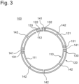
- Fig. 3 is a cross-sectional view of the tubular body along arrows I-I shown in Fig. 2 .
- Fig. 4 is a cross-sectional view of the tubular body of Fig. 3 developed in the circumferential direction.
- the tubular body 100 includes a first sheet material 110, a second sheet material 120, an adhesive layer 130, and vent holes 140.
- the first sheet material 110 and the second sheet material 120 have a circular cross-sectional shape perpendicular to an axial direction.
- the second sheet material 120 is provided on an outer circumference of the first sheet material 110.
- the adhesive layer 130 is provided between the first sheet material 110 and the second sheet material 120, to bond the first sheet material 110 and the second sheet material 120 to each other.
- first sheet material 110 and the second sheet material 120 may be made of paper or cardboard. Therefore, processability of the tubular body 100 can be improved. Note that the first sheet material 110 and the second sheet material 120 may have an elliptical cross-sectional shape perpendicular to the axial direction.
- the first sheet material 110 and the second sheet material 120 are positioned to be shifted from each other and stacked such that ends of the materials in the circumferential direction do not overlap each other.
- the first sheet material 110 includes a first body portion 111, and a first extending portion 112 extending from the first body portion 111 in the circumferential direction with respect to the opposing second sheet material 120.
- the first body portion 111 is a portion opposing the second sheet material 120 in Fig. 4 .
- the second sheet material 120 includes a second body portion 121 and a second extending portion 122 extending from the second body portion 121 in the circumferential direction to the opposing first sheet material 110.
- the second body portion 121 is a portion opposing the first sheet material 110 in Fig. 4 .
- the adhesive layer 130 includes a positioning adhesive layer 131 and a first joint adhesive layer 132 that bond the first body portion 111 and the second body portion 121 to each other, and a second joint adhesive layer 133 (joint adhesive layer) that bonds the first extending portion 112 and the second extending portion 122 to each other.
- the first joint adhesive layer 132 does not necessarily need to be provided, and the positioning adhesive layer 131 may function as the first joint adhesive layer 132.
- the positioning adhesive layer 131, the first joint adhesive layer 132 and the second joint adhesive layer 133 may be made of a kneaded material of modified starch, vinyl acetate or ethylene vinyl acetate, which is an organic polymer, alcohols, and water.
- the positioning adhesive layer 131, the first joint adhesive layer 132 and the second joint adhesive layer 133 are not limited to the above and may be made of another adhesive.
- the tubular body 100 is formed by applying the positioning adhesive layer 131, the first joint adhesive layer 132 and the second joint adhesive layer 133 onto the second sheet material 120, stacking the first sheet material 110 and molding a tubular shape.
- the positioning adhesive layer 131 applied to the second sheet material 120 has an adhesive pattern of a positioning glue (adhesive) applied linearly. Additionally, the positioning adhesive layer 131, the first joint adhesive layer 132 and the second joint adhesive layer 133 may be applied to the first sheet material 110 in place of the second sheet material 120.
- a plurality of vent holes 140 is formed in the circumferential direction of the tubular body 100 through the first sheet material 110 and the second sheet material 120.
- the positioning adhesive layer 131 applied to the second sheet material 120 has an adhesive pattern of the positioning glue (adhesive) applied linearly
- the plurality of vent holes 140 includes a first vent hole 141 in which the adhesive layer 130 is exposed to a hole inner surface of a vent hole 140, and a second vent hole 142 in which the adhesive layer 130 is not exposed to the hole inner surface of the vent hole 140.
- the first vent hole 141 is formed through the first sheet material 110 and the second sheet material 120, together with any of the positioning adhesive layer 131, the first joint adhesive layer 132 and the second joint adhesive layer 133.
- the second vent hole 142 is formed through the first sheet material 110 and the second sheet material 120 at a spot that is not provided with any of the positioning adhesive layer 131, the first joint adhesive layer 132 and the second joint adhesive layer 133.
- the plurality of vent holes 140 includes at least one first vent hole 141 in which the adhesive layer 130 is exposed to the hole inner surface of the vent hole 140, and at least one second vent hole 142 in which the adhesive layer 130 is not exposed to the hole inner surface of the vent hole 140, so that probability of forming the vent hole 140 at a spot provided with the adhesive layer 130 can be reduced, and combustion ash of an adhesive can be inhibited from closing the vent hole 140.
- the flavor generating article 10 to which the tubular body 100 is applied can be inhibited from deteriorating in quality.
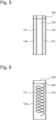
- Fig. 5 is a developed view showing a second sheet material of a tubular body according to one embodiment of the present invention.
- the second sheet material 120 includes a positioning adhesive layer 131 to which a positioning glue is applied in two straight lines parallel to the axial direction.
- the positioning adhesive layer 131 has an adhesive pattern of the positioning glue applied in two straight lines parallel to the axial direction, an amount of adhesive applied can be reduced as compared with a case where the positioning adhesive layer is provided on the entire surface. Furthermore, the probability of forming the vent hole 140 at the spot provided with the adhesive layer 130 can be reduced, and the combustion ash of the adhesive can be inhibited from closing the vent hole 140.
- Fig. 6 is another developed view showing a second sheet material of a tubular body according to one embodiment of the present invention.
- a second sheet material 120 includes a positioning adhesive layer 131 of a positioning glue applied spirally along an axial direction.
- the positioning adhesive layer 131 has an adhesive pattern of the positioning glue applied spirally along the axial direction, an amount of adhesive applied can be reduced as compared with the case where the positioning adhesive layer is provided on the entire surface. Furthermore, the probability of forming the vent hole 140 at the spot provided with the adhesive layer 130 can be reduced, and the combustion ash of the adhesive can be inhibited from closing the vent hole 140.
- Fig. 7 is another developed view showing a second sheet material of a tubular body according to one embodiment of the present invention.
- a second sheet material 120 includes a positioning adhesive layer 131 to which a positioning glue is applied in three straight lines parallel to an axial direction.
- the positioning adhesive layer 131 has an adhesive pattern of the positioning glue applied in three straight lines parallel to the axial direction, the amount of adhesive applied can be reduced as compared with the case where the positioning adhesive layer is provided on the entire surface. Furthermore, the probability of forming the vent hole 140 at the spot provided with the adhesive layer 130 can be reduced, and the combustion ash of the adhesive can be inhibited from closing the vent hole 140.
- Fig. 8 is another developed view showing a second sheet material of a tubular body according to one embodiment of the present invention.
- a second sheet material 120 includes a positioning adhesive layer 131 to which a positioning glue is applied in three straight lines perpendicular to an axial direction.
- the positioning glue may be applied in two lines, or four or more lines.
- the positioning adhesive layer 131 has an adhesive pattern of the positioning glue applied in three straight lines perpendicular to an axial direction, the amount of adhesive applied can be reduced as compared with the case where the positioning adhesive layer is provided on the entire surface. Furthermore, the probability of forming the vent hole 140 at the spot provided with the adhesive layer 130 can be reduced, and the combustion ash of the adhesive can be inhibited from closing the vent hole 140.
- the number of vent holes 140 in a plurality of vent holes 140 is preferably 12 or more and 30 or less, more preferably 21 or less.
- the probability of forming the vent hole 140 at the spot provided with the adhesive layer 130 can be reduced, and the combustion ash of the adhesive can be inhibited from closing the vent hole 140, while introducing sufficient air into an interior.
- the number of first vent holes 141 is 6 or less. By setting the number of the first vent holes 141 to 6 or less, the probability of forming the vent hole 140 at the spot provided with the adhesive layer 130 can be reduced, and the combustion ash of the adhesive can be inhibited from closing the vent hole 140, while introducing sufficient air into the interior.
- a ratio of the number of the first vent holes 141 to the total number of the plurality of vent holes 140 is preferably less than 1/4.
- the plurality of vent holes 140 may be formed in two or more rows along the axial direction. By forming the plurality of vent holes 140 in two or more rows along the axial direction, more air can be introduced into the interior as compared with a case where the plurality of vent holes 140 are formed in one row.
- reduction in amount of adhesive applied also reduces cost. Furthermore, the reduction in amount of adhesive applied reduces glue residue of the adhesive adhering to a manufacturing apparatus of the tubular body 100 and also reduces risk of stopping the manufacturing apparatus, so that a time for removing the glue residue can be shortened, and productivity of the tubular body 100 can be improved.
- FIG. 9 is a configuration diagram showing a tubular body manufacturing apparatus according to one embodiment of the present invention.
- a sheet material 24 having an appropriate width is drawn from a bobbin (not shown) of a sheet material feeding device 22 in a conveying direction 34 and conveyed in a longitudinal direction via a plurality of direction changing rollers 41.
- the sheet material 24 is cut out in the longitudinal direction in a cutting-out part 23. Specifically, the sheet material 24 is cut out into the first sheet material 110 having a first width and the second sheet material 120 having a second width.
- the cut-out first sheet material 110 and second sheet material 120 are conveyed in parallel via the direction changing rollers 41 and separated from each other with a lateral conveying roller 32.
- a gluing part 25 applies the positioning adhesive layer 131, the first joint adhesive layer 132 and the second joint adhesive layer 133 (see Fig. 4 ) over an entire length in the longitudinal direction (applying step).
- the positioning adhesive layer 131 has an adhesive pattern of a positioning glue (adhesive) applied linearly (see Figs. 5 to 8 ).
- a humidification nozzle 26 humidifies the second sheet material 120 (humidification step).
- the humidification nozzle 26 injects water onto the surface of the second sheet material 120 with the positioning adhesive layer 131 applied thereto. Note that the humidification nozzle 26 may inject alcohol onto the second sheet material 120 in place of water or spray steam onto the second sheet material 120.
- spots of the second sheet material 120 with the positioning adhesive layer 131, the first joint adhesive layer 132 and the second joint adhesive layer 133 applied thereto and the other spots have an equivalent humidity.
- the material can be uniformly deformed, and the tubular body 100 having a high roundness can therefore be obtained.
- first sheet material 110 separated from the second sheet material 120, is conveyed and positioned to be shifted in a lateral direction with respect to the conveying direction by a position shifting section 29.
- a pair of tensile rollers 28 integrates the first sheet material 110 and the second sheet material 120 (bonding step).
- the first sheet material 110 and the second sheet material 120 are shifted from each other and bonded such that ends of the materials in a width direction perpendicular to the longitudinal direction do not overlap each other.
- the positioning adhesive layer 131 and the first joint adhesive layer 132, applied to the second sheet material 120 bond the first body portion 111 and the second body portion 121 to each other (see Fig. 4 ).
- the tubular body manufacturing apparatus 1 may include a sensor that detects the ends of the first sheet material 110 and second sheet material 120 in the width direction, and a control mechanism for controlling an amount of position shift between the first sheet material 110 and the second sheet material 120.
- the first sheet material 110 and second sheet material 120, shifted from each other and bonded, are conveyed to a molding device 30.
- a molding device 30 an endless molding belt 43 is guided endlessly via a plurality of direction changing rollers 41.
- the first sheet material 110 and the second sheet material 120 conveyed to the molding device 30 are pressed onto the molding belt 43 by a pressing part 44.
- the molding device 30 molds the first sheet material 110 and the second sheet material 120 into a tubular continuous body 31, for example, by a known method described in Japanese Patent Laid-Open No. 2018-121628 (molding step).
- the second joint adhesive layer 133 applied to the second sheet material 120 bonds the first extending portion 112 and the second extending portion 122 to each other (see Fig. 4 ).
- first sheet material 110 and second sheet material 120 molded into the tubular continuous body 31 are heated by a heating part 37, to thereby cure the positioning adhesive layer 131, the first joint adhesive layer 132 and the second joint adhesive layer 133. Furthermore, the second sheet material 120 humidified by the humidification nozzle 26 is also dried in the heating part 37.
- a cutting part 38 cuts, to a predetermined length, the first sheet material 110 and second sheet material 120 molded into the tubular continuous body 31 (cutting step), to form the tubular body 100.
- the first sheet material 110 and the second sheet material 120 may be replaced with each other.
- the tubular body 100 is incorporated into a semi-finished product of the flavor generating article or the smoking article and then irradiated with laser beams from an outer circumference toward an inner circumference of the tubular body 100, and the materials at irradiated spots are combusted, to form a plurality of vent holes 140 extending through the tubular body 100 intermittently over an entire circumference in the circumferential direction.
- FIG. 10 is an explanatory diagram showing experimental results of humidification conditions in a tubular body manufacturing apparatus according to one embodiment of the present invention. Such an experiment was performed by changing the humidification conditions when the positioning glue was applied, onto the second sheet material 120, in three straight lines parallel to the axial direction (see Fig. 7 ).
- Fig. 11 shows humidification conditions for each adhesive pattern in the tubular body manufacturing apparatus 1.
- Fig. 12 shows the result of comparison with a conventional product in terms of the application amount of the positioning adhesive layer 131 in the tubular body 100.
- the application amount of the positioning adhesive layer 131 can be reduced by 80% as compared with the conventional product (application amount of 100 g/500 m (24 mg/line)). Furthermore, in the tubular body 100 to which the positioning glue is applied in two lines, the application amount of the positioning adhesive layer 131 can be reduced by 75% as compared with the conventional product.
- the tubular body 100 (see Fig. 6 ) with the positioning glue applied, to the second sheet material 120, spirally along the axial direction and a tubular body 100 (see Fig. 5 ) with the positioning glue applied, to the second sheet material 120, in two straight lines parallel to the axial direction were manufactured and measured for various physical properties.
- Fig. 13 shows results of comparison of the standard product with the conventional product in terms of various physical properties of the tubular body 100.
- the physical properties of the tubular body 100 immediately after the formation of the tubular body 100 and after 24 hours were measured in consideration of influence of humidification by the humidification nozzle 26, for the tubular body 100 with the positioning glue applied spirally and the tubular body 100 with the positioning glue applied in two lines. In addition, moisture was measured after one week.
- the tubular body 100 has a weight equivalent to that of the conventional product immediately after formed and tends to be lighter in weight due to decrease in moisture with elapse of time. It was also confirmed that a circumference length and hardness have a value varying with the decrease in moisture with elapse of time.
- both the tubular body 100 with the positioning glue applied spirally and the tubular body 100 with the positioning glue applied in two lines have roundness equivalent to that of the standard product. Furthermore, both the tubular body 100 with the positioning glue applied spirally and the tubular body 100 with the positioning glue applied in two lines have the same structure of a joint portion between the first extending portion 112 and the second extending portion 122 as in the conventional product and therefore indicate a value of joint peel strength equal to that of the conventional product.
- an area of the positioning adhesive layer 131 to 10% or more and 50% or less of an area of an overlapping portion between the first body portion and the second body portion, a tubular body capable of suppressing an adhering defect between the first sheet material 110 and the second sheet material 120 and having excellent roundness and less influence on flavor and smoking taste can be obtained.
Landscapes
- Making Paper Articles (AREA)
- Adhesives Or Adhesive Processes (AREA)
- Adhesive Tapes (AREA)
Abstract
Description
- The present invention relates to a tubular body.
- Conventionally, a double-layered tube (tubular body) manufactured from first and second material strip portions is known (see, for example, PTL 1). This double-layered tube is applicable, for example, to a flavor generating article for use in a non-combustible flavor inhaler for inhaling flavor or the like without combusting any material, or to a combustible smoking article.
- In this tube, the second material strip portion is disposed around the first material strip portion, and the first and second material strip portions have abutment edges wound to be shifted from each other in a circumferential direction. Furthermore, in this tube, a positioning adhesive and a joint adhesive (collectively referred to as an adhesive) are provided on the entire surface or almost the entire surface between the first material strip portion and the second material strip portion.
- PTL 1:
Japanese Patent Laid-Open No. 2018-93867 - When a tube described in
PTL 1 is applied to a flavor generating article or a smoking article, this application includes incorporating the tube into a semifinished product of the flavor generating article or the smoking article, then irradiating the tube with laser beams from an outer circumference toward an inner circumference of the tube and combusting a material of the tube at irradiated spots. Consequently, vent holes extending through the tube can be formed intermittently over an entire circumference of the tube in a circumferential direction. - Here, in the tube described in
PTL 1, an adhesive is provided on the entire surface or almost the entire surface between a first material strip portion and a second material strip portion. Therefore, when forming the vent holes, combustion ash of the adhesive may close the vent holes. - Specifically, paper constituting the tube is, for example, organic wood pulp (almost pure cellulose from which lignin, hemicellulose, and the like contained in trees are removed) and an inorganic filler (calcium carbonate), and the combustion ash generated by irradiation with laser beams is mainly calcium carbonate.
- In contrast, the adhesive is, for example, a kneaded material of modified starch, vinyl acetate or ethylene vinyl acetate, which is an organic polymer, alcohols and water, and the combustion ash generated by the irradiation with laser beams contains organic polymers left over from combustion.
- Therefore, the combustion ash in the vent holes formed at spots to which the adhesive is applied is a mixture of calcium carbonate and organic polymers and is stickier and more likely to close the vent holes than calcium carbonate-dominant combustion ash in the vent holes formed at spots to which the adhesive is not applied.
- If the tube with the vent holes closed is applied to the flavor generating article or the smoking article, air is not introduced from the vent holes into the flavor generating article or the smoking article. Consequently, aerosol generated by heating the flavor generating article or by combusting the smoking article is not cooled, and aerosol concentration is not reduced. There is therefore concern that the flavor generating article or the smoking article deteriorates in quality.
- The present invention has been made to solve at least some of such problems as described above, and an object of the present invention is to obtain a tubular body capable of inhibiting combustion ash of an adhesive from closing vent holes if the vent holes are formed.
- In a first aspect of the present invention, a tubular body is provided. This tubular body includes a first sheet material that has a circular or elliptical cross-sectional shape perpendicular to an axial direction, a second sheet material that is provided on an outer circumference of the first sheet material and that has a circular or elliptical cross-sectional shape perpendicular to the axial direction, an adhesive layer that is provided between the first sheet material and the second sheet material and that bonds the first sheet material and the second sheet material to each other, and a plurality of vent holes formed in a circumferential direction of the tubular body through the first sheet material and the second sheet material, wherein the plurality of vent holes including at least one first vent hole in which the adhesive layer is exposed to a hole inner surface of the vent hole, and at least one second vent hole in which the adhesive layer is not exposed to the hole inner surface of the vent hole.
- According to the first aspect of the present invention, the plurality of vent holes includes the at least one first vent hole in which the adhesive layer is exposed to the hole inner surface of the vent hole, and the at least one second vent hole in which the adhesive layer is not exposed to the hole inner surface of the vent hole. Consequently, probability of forming the vent hole at a spot provided with the adhesive layer can be reduced, and combustion ash of an adhesive can be inhibited from closing the vent holes.
- For a second aspect of the present invention, in the first aspect, the first sheet material and the second sheet material are shifted from each other and stacked such that ends of the first and second sheet materials in the circumferential direction do not overlap each other, the first sheet material includes a first body portion, and a first extending portion extending from the first body portion in the circumferential direction with respect to the opposing second sheet material, the second sheet material includes a second body portion, and a second extending portion extending from the second body portion in the circumferential direction with respect to the opposing first sheet material, the adhesive layer includes a positioning adhesive layer that bonds the first body portion and the second body portion to each other, and a joint adhesive layer that bonds the first extending portion and the second extending portion to each other, and the positioning adhesive layer has an adhesive pattern of a positioning glue applied linearly.
- According to the second aspect of the present invention, since the positioning adhesive layer bonding the first body portion of the first sheet material and the second body portion of the second sheet material to each other has the adhesive pattern of the positioning glue applied linearly, an amount of adhesive applied can be reduced as compared with a case where the positioning adhesive layer is provided on the entire surface.
- For a third aspect of the present invention, in the second aspect, the positioning glue is applied linearly in two or more lines.
- According to the third aspect of the present invention, since the positioning adhesive layer has an adhesive pattern of the positioning glue applied linearly in two or more lines, the amount of adhesive applied can be reduced as compared with the case where the positioning adhesive layer is provided on the entire surface.
- For a fourth aspect of the present invention, in the third aspect, the positioning glue is applied in a straight line.
- According to the fourth aspect of the present invention, since the positioning adhesive layer has an adhesive pattern of the positioning glue applied in two or more straight lines, the amount of adhesive applied can be reduced as compared with the case where the positioning adhesive layer is provided on the entire surface.
- For a fifth aspect of the present invention, in the fourth aspect, the positioning glue is applied in a straight line parallel to the axial direction.
- According to the fifth aspect of the present invention, since the positioning adhesive layer has an adhesive pattern of the positioning glue applied in two or more straight lines parallel to the axial direction, the amount of adhesive applied can be reduced as compared with the case where the positioning adhesive layer is provided on the entire surface.
- For a sixth aspect of the present invention, in the fourth aspect, the positioning glue is applied in a straight line perpendicular to the axial direction.
- According to the sixth aspect of the present invention, since the positioning adhesive layer has an adhesive pattern of the positioning glue applied in two or more lines perpendicular to the axial direction, the amount of adhesive applied can be reduced as compared with the case where the positioning adhesive layer is provided on the entire surface.
- For a seventh aspect of the present invention, in the second aspect, the positioning glue is applied spirally along the axial direction.
- According to the seventh aspect of the present invention, since the positioning adhesive layer has an adhesive pattern of the positioning glue applied spirally along the axial direction, the amount of adhesive applied can be reduced as compared with the case where the positioning adhesive layer is provided on the entire surface.
- For an eighth aspect of the present invention, in any one of the first to seventh aspects, each of the first sheet material and the second sheet material is paper.
- According to the eighth aspect of the present invention, the first sheet material and second sheet material made of paper can improve processability of the tubular body.
- For a ninth aspect of the present invention, in any one of the first to eighth aspects, the number of vent holes in the plurality of vent holes is 12 or more and 30 or less.
- According to the ninth aspect of the present invention, by setting the number of the vent holes in the plurality of vent holes to 12 or more and 30 or less, the probability of forming the vent hole at the spot provided with the adhesive layer can be reduced, and combustion ash of the adhesive can be inhibited from closing the vent holes, while introducing sufficient air into an interior.
- For a tenth aspect of the present invention, in the ninth aspect, the number of vent holes in the plurality of vent holes is 21 or less.
- According to the tenth aspect of the present invention, by setting the number of the vent holes in the plurality of vent holes to 12 or more and 21 or less, the probability of forming the vent hole at the spot provided with the adhesive layer can be reduced, and the combustion ash of the adhesive can be inhibited from closing the vent holes, while introducing sufficient air into the interior.
- For an eleventh aspect of the present invention, in any one of the first to tenth aspects, the number of vent holes in the first vent holes is 6 or less.
- According to the eleventh aspect of the present invention, by setting the number of the vent holes in the first vent holes to 6 or less, the probability of forming the vent hole at the spot provided with the adhesive layer can be reduced, and the combustion ash of the adhesive can be inhibited from closing the vent holes, while introducing sufficient air into the interior.
- For a twelfth aspect of the present invention, in any one of the first to eleventh aspects, a ratio of the number of vent holes in the first vent holes to the total number of vent holes in the plurality of vent holes is less than 1/4.
- According to the twelfth aspect of the present invention, by setting the ratio of the number of the vent holes in the first vent holes to the total number of the vent holes in the plurality of vent holes to less than 1/4, the probability of forming the vent hole at the spot provided with the adhesive layer can be reduced, and the combustion ash of the adhesive can be inhibited from closing the vent holes, while introducing sufficient air into the interior.
- For a thirteenth aspect of the present invention, in any one of the first to twelfth aspects, the plurality of vent holes is formed in two or more rows along the axial direction.
- According to the thirteenth aspect of the present invention, by forming the plurality of vent holes in two or more rows along the axial direction, more air can be introduced into the interior as compared with a case where the plurality of vent holes is formed in one row.
-
-
Fig. 1 is a cross-sectional view showing a flavor generating article to which a tubular body according to one embodiment of the present invention is applied. -
Fig. 2 is a perspective view showing a tubular body according to one embodiment of the present invention. -
Fig. 3 is a cross-sectional view of the tubular body along arrows I-I shown inFig. 2 . -
Fig. 4 is a cross-sectional view showing the tubular body ofFig. 3 developed in a circumferential direction. -
Fig. 5 is a developed view showing a second sheet material of a tubular body according to one embodiment of the present invention. -
Fig. 6 is another developed view showing a second sheet material of a tubular body according to one embodiment of the present invention. -
Fig. 7 is still another developed view showing a second sheet material of a tubular body according to one embodiment of the present invention. -
Fig. 8 is a further developed view showing a second sheet material of a tubular body according to one embodiment of the present invention. -
Fig. 9 is a configuration diagram showing a tubular body manufacturing apparatus according to one embodiment of the present invention. -
Fig. 10 is an explanatory diagram showing experimental results of humidification conditions in a tubular body manufacturing apparatus according to one embodiment of the present invention. -
Fig. 11 is an explanatory diagram showing humidification conditions for each adhesive pattern in a tubular body manufacturing apparatus according to one embodiment of the present invention. -
Fig. 12 is an explanatory diagram showing an amount of adhesive applied in a tubular body according to one embodiment of the present invention in comparison with a conventional product. -
Fig. 13 is an explanatory diagram showing various physical properties of a tubular body according to one embodiment of the present invention in comparison of a standard product with the conventional product. - Hereinafter, embodiments of the present invention will be described with reference to the drawings. In the drawings described below, identical, or corresponding components are denoted with the same signs and duplicate descriptions are omitted. A tubular body according to the present invention may be applied, for example, to a flavor generating article for use in a non-combustible flavor inhaler for inhaling flavor or the like without combusting any material. The tubular body according to the present invention may be applied to a combustible smoking article.
-
Fig. 1 is a cross-sectional view showing a flavor generating article to which a tubular body according to one embodiment of the present invention is applied. As shown inFig. 1 , aflavor generating article 10 includes a tobacco-containingsegment 11 and amouthpiece segment 12. Themouthpiece segment 12 includes acooling segment 13, acenter hole segment 14, and afilter segment 15. - In use, the tobacco-containing
segment 11 is heated and inhaled from an end of thefilter segment 15. Note that a position of thecenter hole segment 14 is not limited to a position shown inFig. 1 and, for example, the position of thecenter hole segment 14 may be replaced with that of thefilter segment 15. Furthermore, in theflavor generating article 10 shown inFig. 1 , thecenter hole segment 14 may be omitted. - The tobacco-containing
segment 11 includes atobacco filler 210 containing tobacco and an aerosol source, and atubular wrapper 220 wrapping thetobacco filler 210. Thetobacco filler 210 may further contain a volatile flavoring ingredient, water, and the like. A size of tobacco for use as a filler or a method of preparing the tobacco is not particularly limited. - The cooling
segment 13 includes atubular body 100. In thetubular body 100 andmouthpiece lining paper 400 described later, a plurality of vent holes 140 extending through walls of both the tubular body and the mouthpiece lining paper is formed concentrically in a circumferential direction of thetubular body 100. Eachvent hole 140 is a hole for promoting inflow of air from outside by user's inhalation, and the inflow of air cools aerosol generated in thetobacco filler 210 and reduces aerosol concentration. A diameter (delivery length) of thevent hole 140 is not particularly limited, but may be, for example, from 0.5 mm to 1.5 mm. - The
center hole segment 14 includes afilling layer 310 having a hollow portion and a firstinner plug wrapper 320 wrapping thefilling layer 310. Thefilling layer 310 can be, for example, a rod into which cellulose acetate fibers are highly densely filled and a plasticizer containing triacetin is added and cured. - The hollow portion has a diameter that is not particularly limited and that may be, for example, from 1.0 mm to 5.0 mm. Since the
filling layer 310 has a high fiber filling density, air, and aerosol flow only through the hollow portion during inhaling, and barely flow in thefilling layer 310. Since thefilling layer 310 includes the hollow portion, an amount of aerosol to be filtered can be reduced, the aerosol containing flavor ingredients generated by heating theflavor generating article 10. - The
filter segment 15 includes afilter medium 330, and a tubular secondinner plug wrapper 340 wrapping thefilter medium 330. Thefilter medium 330 may be a solid plug filled with a porous material. Since thefilter segment 15 includes the solid plug, a delivery amount of aerosol can be appropriately adjusted by filtering the aerosol containing the flavor ingredients generated by heating theflavor generating article 10. - The
center hole segment 14 and thefilter segment 15 are connected to each other with anouter plug wrapper 350. Theouter plug wrapper 350 may be, for example, cylindrical paper. Furthermore, the tobacco-containingsegment 11, the coolingsegment 13, and the connectedcenter hole segment 14 andfilter segment 15 are wrapped in themouthpiece lining paper 400 and mutually connected, the mouthpiece lining paper having an inner surface with a glue such as vinyl acetate glue applied thereto. - Hereinafter, the
tubular body 100 shown inFig. 1 will be described in detail.Fig. 2 is a perspective view showing a tubular body according to one embodiment of the present invention.Fig. 3 is a cross-sectional view of the tubular body along arrows I-I shown inFig. 2 .Fig. 4 is a cross-sectional view of the tubular body ofFig. 3 developed in the circumferential direction. - As shown in
Figs. 2 to 4 , thetubular body 100 includes afirst sheet material 110, asecond sheet material 120, anadhesive layer 130, and ventholes 140. Thefirst sheet material 110 and thesecond sheet material 120 have a circular cross-sectional shape perpendicular to an axial direction. Thesecond sheet material 120 is provided on an outer circumference of thefirst sheet material 110. Theadhesive layer 130 is provided between thefirst sheet material 110 and thesecond sheet material 120, to bond thefirst sheet material 110 and thesecond sheet material 120 to each other. - Each of the
first sheet material 110 and thesecond sheet material 120 may be made of paper or cardboard. Therefore, processability of thetubular body 100 can be improved. Note that thefirst sheet material 110 and thesecond sheet material 120 may have an elliptical cross-sectional shape perpendicular to the axial direction. - Here, the
first sheet material 110 and thesecond sheet material 120 are positioned to be shifted from each other and stacked such that ends of the materials in the circumferential direction do not overlap each other. Thefirst sheet material 110 includes afirst body portion 111, and a first extendingportion 112 extending from thefirst body portion 111 in the circumferential direction with respect to the opposingsecond sheet material 120. Thefirst body portion 111 is a portion opposing thesecond sheet material 120 inFig. 4 . - The
second sheet material 120 includes asecond body portion 121 and a second extendingportion 122 extending from thesecond body portion 121 in the circumferential direction to the opposingfirst sheet material 110. Thesecond body portion 121 is a portion opposing thefirst sheet material 110 inFig. 4 . - The
adhesive layer 130 includes a positioningadhesive layer 131 and a first jointadhesive layer 132 that bond thefirst body portion 111 and thesecond body portion 121 to each other, and a second joint adhesive layer 133 (joint adhesive layer) that bonds the first extendingportion 112 and the second extendingportion 122 to each other. The first jointadhesive layer 132 does not necessarily need to be provided, and the positioningadhesive layer 131 may function as the first jointadhesive layer 132. - The positioning
adhesive layer 131, the first jointadhesive layer 132 and the second jointadhesive layer 133 may be made of a kneaded material of modified starch, vinyl acetate or ethylene vinyl acetate, which is an organic polymer, alcohols, and water. The positioningadhesive layer 131, the first jointadhesive layer 132 and the second jointadhesive layer 133 are not limited to the above and may be made of another adhesive. - The
tubular body 100 is formed by applying the positioningadhesive layer 131, the first jointadhesive layer 132 and the second jointadhesive layer 133 onto thesecond sheet material 120, stacking thefirst sheet material 110 and molding a tubular shape. Here, the positioningadhesive layer 131 applied to thesecond sheet material 120 has an adhesive pattern of a positioning glue (adhesive) applied linearly. Additionally, the positioningadhesive layer 131, the first jointadhesive layer 132 and the second jointadhesive layer 133 may be applied to thefirst sheet material 110 in place of thesecond sheet material 120. - A plurality of vent holes 140 is formed in the circumferential direction of the
tubular body 100 through thefirst sheet material 110 and thesecond sheet material 120. Here, since the positioningadhesive layer 131 applied to thesecond sheet material 120 has an adhesive pattern of the positioning glue (adhesive) applied linearly, the plurality of vent holes 140 includes afirst vent hole 141 in which theadhesive layer 130 is exposed to a hole inner surface of avent hole 140, and asecond vent hole 142 in which theadhesive layer 130 is not exposed to the hole inner surface of thevent hole 140. - Specifically, the
first vent hole 141 is formed through thefirst sheet material 110 and thesecond sheet material 120, together with any of the positioningadhesive layer 131, the first jointadhesive layer 132 and the second jointadhesive layer 133. Furthermore, thesecond vent hole 142 is formed through thefirst sheet material 110 and thesecond sheet material 120 at a spot that is not provided with any of the positioningadhesive layer 131, the first jointadhesive layer 132 and the second jointadhesive layer 133. - As described above, the plurality of vent holes 140 includes at least one
first vent hole 141 in which theadhesive layer 130 is exposed to the hole inner surface of thevent hole 140, and at least onesecond vent hole 142 in which theadhesive layer 130 is not exposed to the hole inner surface of thevent hole 140, so that probability of forming thevent hole 140 at a spot provided with theadhesive layer 130 can be reduced, and combustion ash of an adhesive can be inhibited from closing thevent hole 140. As a result, theflavor generating article 10 to which thetubular body 100 is applied can be inhibited from deteriorating in quality. -
Fig. 5 is a developed view showing a second sheet material of a tubular body according to one embodiment of the present invention. As shown inFig. 5 , thesecond sheet material 120 includes a positioningadhesive layer 131 to which a positioning glue is applied in two straight lines parallel to the axial direction. - Thus, since the positioning
adhesive layer 131 has an adhesive pattern of the positioning glue applied in two straight lines parallel to the axial direction, an amount of adhesive applied can be reduced as compared with a case where the positioning adhesive layer is provided on the entire surface. Furthermore, the probability of forming thevent hole 140 at the spot provided with theadhesive layer 130 can be reduced, and the combustion ash of the adhesive can be inhibited from closing thevent hole 140. - Note that the adhesive pattern of the positioning
adhesive layer 131 is not limited to that shown inFig. 5. Fig. 6 is another developed view showing a second sheet material of a tubular body according to one embodiment of the present invention. As shown inFig. 6 , asecond sheet material 120 includes a positioningadhesive layer 131 of a positioning glue applied spirally along an axial direction. - Thus, since the positioning
adhesive layer 131 has an adhesive pattern of the positioning glue applied spirally along the axial direction, an amount of adhesive applied can be reduced as compared with the case where the positioning adhesive layer is provided on the entire surface. Furthermore, the probability of forming thevent hole 140 at the spot provided with theadhesive layer 130 can be reduced, and the combustion ash of the adhesive can be inhibited from closing thevent hole 140. -
Fig. 7 is another developed view showing a second sheet material of a tubular body according to one embodiment of the present invention. As shown inFig. 7 , asecond sheet material 120 includes a positioningadhesive layer 131 to which a positioning glue is applied in three straight lines parallel to an axial direction. - Thus, since the positioning
adhesive layer 131 has an adhesive pattern of the positioning glue applied in three straight lines parallel to the axial direction, the amount of adhesive applied can be reduced as compared with the case where the positioning adhesive layer is provided on the entire surface. Furthermore, the probability of forming thevent hole 140 at the spot provided with theadhesive layer 130 can be reduced, and the combustion ash of the adhesive can be inhibited from closing thevent hole 140. -
Fig. 8 is another developed view showing a second sheet material of a tubular body according to one embodiment of the present invention. As shown inFig. 8 , asecond sheet material 120 includes a positioningadhesive layer 131 to which a positioning glue is applied in three straight lines perpendicular to an axial direction. The positioning glue may be applied in two lines, or four or more lines. - Thus, since the positioning
adhesive layer 131 has an adhesive pattern of the positioning glue applied in three straight lines perpendicular to an axial direction, the amount of adhesive applied can be reduced as compared with the case where the positioning adhesive layer is provided on the entire surface. Furthermore, the probability of forming thevent hole 140 at the spot provided with theadhesive layer 130 can be reduced, and the combustion ash of the adhesive can be inhibited from closing thevent hole 140. - Here, the number of vent holes 140 in a plurality of vent holes 140 is preferably 12 or more and 30 or less, more preferably 21 or less. By setting the number of the vent holes 140 in the plurality of vent holes 140 to 12 or more and 30 or less, more preferably 21 or less, the probability of forming the
vent hole 140 at the spot provided with theadhesive layer 130 can be reduced, and the combustion ash of the adhesive can be inhibited from closing thevent hole 140, while introducing sufficient air into an interior. - It is also preferable that the number of first vent holes 141 is 6 or less. By setting the number of the first vent holes 141 to 6 or less, the probability of forming the
vent hole 140 at the spot provided with theadhesive layer 130 can be reduced, and the combustion ash of the adhesive can be inhibited from closing thevent hole 140, while introducing sufficient air into the interior. - Furthermore, a ratio of the number of the first vent holes 141 to the total number of the plurality of vent holes 140 is preferably less than 1/4. By setting the ratio of the number of the first vent holes 141 to the total number of the plurality of vent holes 140 to less than 1/4, the probability of forming the
vent hole 140 at the spot provided with theadhesive layer 130 can be reduced, and the combustion ash of the adhesive can be inhibited from closing thevent hole 140, while introducing sufficient air into the interior. - Note that the plurality of vent holes 140 may be formed in two or more rows along the axial direction. By forming the plurality of vent holes 140 in two or more rows along the axial direction, more air can be introduced into the interior as compared with a case where the plurality of vent holes 140 are formed in one row.
- Furthermore, by reducing the amount of adhesive applied by use of the
second sheet materials 120 shown inFigs. 5 to 8 , adhesive ingredients generated by heating or combusting from thetubular body 100 applied to a flavor generating article or a smoking article are reduced, and flavor of the flavor generating article or smoking taste of the smoking article is inhibited from deteriorating. - In addition, reduction in amount of adhesive applied also reduces cost. Furthermore, the reduction in amount of adhesive applied reduces glue residue of the adhesive adhering to a manufacturing apparatus of the
tubular body 100 and also reduces risk of stopping the manufacturing apparatus, so that a time for removing the glue residue can be shortened, and productivity of thetubular body 100 can be improved. - Next, a method for manufacturing the
tubular body 100 will be described.Fig. 9 is a configuration diagram showing a tubular body manufacturing apparatus according to one embodiment of the present invention. In a tubularbody manufacturing apparatus 1 shown inFig. 9 , asheet material 24 having an appropriate width is drawn from a bobbin (not shown) of a sheetmaterial feeding device 22 in a conveyingdirection 34 and conveyed in a longitudinal direction via a plurality ofdirection changing rollers 41. - The
sheet material 24 is cut out in the longitudinal direction in a cutting-outpart 23. Specifically, thesheet material 24 is cut out into thefirst sheet material 110 having a first width and thesecond sheet material 120 having a second width. The cut-outfirst sheet material 110 andsecond sheet material 120 are conveyed in parallel via thedirection changing rollers 41 and separated from each other with alateral conveying roller 32. - After the
direction changing rollers 41 change a direction of thesecond sheet material 120, a gluingpart 25 applies the positioningadhesive layer 131, the first jointadhesive layer 132 and the second joint adhesive layer 133 (seeFig. 4 ) over an entire length in the longitudinal direction (applying step). Here, the positioningadhesive layer 131 has an adhesive pattern of a positioning glue (adhesive) applied linearly (seeFigs. 5 to 8 ). - Subsequently, a
humidification nozzle 26 humidifies the second sheet material 120 (humidification step). Thehumidification nozzle 26 injects water onto the surface of thesecond sheet material 120 with the positioningadhesive layer 131 applied thereto. Note that thehumidification nozzle 26 may inject alcohol onto thesecond sheet material 120 in place of water or spray steam onto thesecond sheet material 120. - Thus, spots of the
second sheet material 120 with the positioningadhesive layer 131, the first jointadhesive layer 132 and the second jointadhesive layer 133 applied thereto and the other spots have an equivalent humidity. In a subsequent step of molding thesecond sheet material 120 into a tubular shape, the material can be uniformly deformed, and thetubular body 100 having a high roundness can therefore be obtained. - In contrast, the
first sheet material 110, separated from thesecond sheet material 120, is conveyed and positioned to be shifted in a lateral direction with respect to the conveying direction by aposition shifting section 29. Afterward, a pair oftensile rollers 28 integrates thefirst sheet material 110 and the second sheet material 120 (bonding step). - Consequently, the
first sheet material 110 and thesecond sheet material 120 are shifted from each other and bonded such that ends of the materials in a width direction perpendicular to the longitudinal direction do not overlap each other. Specifically, the positioningadhesive layer 131 and the first jointadhesive layer 132, applied to thesecond sheet material 120, bond thefirst body portion 111 and thesecond body portion 121 to each other (seeFig. 4 ). - Note that the tubular
body manufacturing apparatus 1 may include a sensor that detects the ends of thefirst sheet material 110 andsecond sheet material 120 in the width direction, and a control mechanism for controlling an amount of position shift between thefirst sheet material 110 and thesecond sheet material 120. - Next, the
first sheet material 110 andsecond sheet material 120, shifted from each other and bonded, are conveyed to amolding device 30. In themolding device 30, anendless molding belt 43 is guided endlessly via a plurality ofdirection changing rollers 41. Thefirst sheet material 110 and thesecond sheet material 120 conveyed to themolding device 30 are pressed onto themolding belt 43 by apressing part 44. - Afterward, the
molding device 30 molds thefirst sheet material 110 and thesecond sheet material 120 into a tubularcontinuous body 31, for example, by a known method described inJapanese Patent Laid-Open No. 2018-121628 adhesive layer 133 applied to thesecond sheet material 120 bonds the first extendingportion 112 and the second extendingportion 122 to each other (seeFig. 4 ). - Subsequently, the
first sheet material 110 andsecond sheet material 120 molded into the tubularcontinuous body 31 are heated by aheating part 37, to thereby cure the positioningadhesive layer 131, the first jointadhesive layer 132 and the second jointadhesive layer 133. Furthermore, thesecond sheet material 120 humidified by thehumidification nozzle 26 is also dried in theheating part 37. - Next, a cutting
part 38 cuts, to a predetermined length, thefirst sheet material 110 andsecond sheet material 120 molded into the tubular continuous body 31 (cutting step), to form thetubular body 100. In the tubularbody manufacturing apparatus 1, thefirst sheet material 110 and thesecond sheet material 120 may be replaced with each other. - Subsequently, the
tubular body 100 is incorporated into a semi-finished product of the flavor generating article or the smoking article and then irradiated with laser beams from an outer circumference toward an inner circumference of thetubular body 100, and the materials at irradiated spots are combusted, to form a plurality of vent holes 140 extending through thetubular body 100 intermittently over an entire circumference in the circumferential direction. - Next, results of various experiments performed by use of the tubular
body manufacturing apparatus 1 will be described. First, an experiment was performed to find out appropriate humidification conditions by thehumidification nozzle 26.Fig. 10 is an explanatory diagram showing experimental results of humidification conditions in a tubular body manufacturing apparatus according to one embodiment of the present invention. Such an experiment was performed by changing the humidification conditions when the positioning glue was applied, onto thesecond sheet material 120, in three straight lines parallel to the axial direction (seeFig. 7 ). - As shown in
Fig. 10 , when thetubular body 100 was manufactured while changing the humidification conditions fromlevel 1 tolevel 9 for a water content, an injection pressure, and a distance from thehumidification nozzle 26 to the second sheet material 120 (humidification nozzle distance), it was confirmed that level 6 (water content of 6.34 mg/line, injection pressure of 0.05 MPa, humidification nozzle distance of 17 mm) was appropriate in roundness and circumferential length. - Subsequently, according to the
level 6 shown inFig. 10 , when manufacturing the tubular body 100 (seeFig. 6 ) with the positioning glue applied, onto thesecond sheet material 120, spirally along the axial direction, bonding of the first extendingportion 112 and the second extendingportion 122 by the second joint adhesive layer 133 (seeFig. 4 ) was not appropriately performed. - Then, an experiment was performed on the tubular body 100 (see
Fig. 6 ) with a positioning glue applied spirally along the axial direction to thesecond sheet material 120, while changing the water content. As a result, it was confirmed that a water content of 28.20 mg/line is appropriate for thetubular body 100 with the positioning glue applied spirally.Fig. 11 shows humidification conditions for each adhesive pattern in the tubularbody manufacturing apparatus 1. - Next, an experiment was performed while changing an application amount of the positioning
adhesive layer 131, for the tubular body 100 (seeFig. 6 ) with the positioning glue applied, to thesecond sheet material 120, spirally along the axial direction, and the tubular body 100 (seeFig. 5 ) with the positioning glue applied, to thesecond sheet material 120, in two straight lines parallel to the axial direction. - As a result, it was confirmed that an application amount of 20 g/500 m (4.8 mg/line) is appropriate for the
tubular body 100 with the positioning glue applied spirally, and 25 g/500 m (3.0 mg/line × 2) is appropriate for thetubular body 100 with the positioning glue applied in two lines.Fig. 12 shows the result of comparison with a conventional product in terms of the application amount of the positioningadhesive layer 131 in thetubular body 100. - As shown in
Fig. 12 , in thetubular body 100 to which the positioning glue is applied spirally, the application amount of the positioningadhesive layer 131 can be reduced by 80% as compared with the conventional product (application amount of 100 g/500 m (24 mg/line)). Furthermore, in thetubular body 100 to which the positioning glue is applied in two lines, the application amount of the positioningadhesive layer 131 can be reduced by 75% as compared with the conventional product. - Subsequently, on the humidification conditions and with the application amount of the positioning
adhesive layer 131 as shown inFigs. 11 and12 , the tubular body 100 (seeFig. 6 ) with the positioning glue applied, to thesecond sheet material 120, spirally along the axial direction and a tubular body 100 (seeFig. 5 ) with the positioning glue applied, to thesecond sheet material 120, in two straight lines parallel to the axial direction were manufactured and measured for various physical properties.Fig. 13 shows results of comparison of the standard product with the conventional product in terms of various physical properties of thetubular body 100. - Here, the physical properties of the
tubular body 100 immediately after the formation of thetubular body 100 and after 24 hours were measured in consideration of influence of humidification by thehumidification nozzle 26, for thetubular body 100 with the positioning glue applied spirally and thetubular body 100 with the positioning glue applied in two lines. In addition, moisture was measured after one week. - As shown in
Fig. 13 , it was confirmed that thetubular body 100 has a weight equivalent to that of the conventional product immediately after formed and tends to be lighter in weight due to decrease in moisture with elapse of time. It was also confirmed that a circumference length and hardness have a value varying with the decrease in moisture with elapse of time. - It was also confirmed that both the
tubular body 100 with the positioning glue applied spirally and thetubular body 100 with the positioning glue applied in two lines have roundness equivalent to that of the standard product. Furthermore, both thetubular body 100 with the positioning glue applied spirally and thetubular body 100 with the positioning glue applied in two lines have the same structure of a joint portion between the first extendingportion 112 and the second extendingportion 122 as in the conventional product and therefore indicate a value of joint peel strength equal to that of the conventional product. - In addition, by setting an area of the positioning
adhesive layer 131 to 10% or more and 50% or less of an area of an overlapping portion between the first body portion and the second body portion, a tubular body capable of suppressing an adhering defect between thefirst sheet material 110 and thesecond sheet material 120 and having excellent roundness and less influence on flavor and smoking taste can be obtained. - As described above, embodiments of the present invention have been described, and the embodiments of the above-described invention are for facilitating understanding of the present invention and are not intended to limit the present invention. The present invention may be modified or improved without departing from its gist, and the present invention includes equivalents thereto. Furthermore, respective components described in the claims and the specification can be combined or omitted to such an extent that at least some of the above-described issues can be solved or at least some of effects are achieved.
-
- 1
- tubular body manufacturing apparatus
- 10
- flavor generating article
- 11
- tobacco-containing segment
- 12
- mouthpiece segment
- 13
- cooling segment
- 14
- center hole segment
- 15
- filter segment
- 22
- sheet material feeding device
- 23
- cutting-out part
- 24
- sheet material
- 25
- gluing part
- 26
- humidification nozzle
- 28
- pair of tensile rollers
- 29
- position shifting section
- 30
- molding device
- 31
- tubular continuous body
- 32
- lateral conveying roller
- 34
- conveying direction
- 37
- heating part
- 38
- cutting part
- 41
- direction changing rollers
- 43
- molding belt
- 44
- pressing part
- 100
- tubular body
- 110
- first sheet material
- 111
- first body portion
- 112
- first extending portion
- 120
- second sheet material
- 121
- second body portion
- 122
- second extending portion
- 130
- adhesive layer
- 131
- positioning adhesive layer
- 132
- first joint adhesive layer
- 133
- second joint adhesive layer
- 140
- vent hole
- 141
- first vent hole
- 142
- second vent hole
- 210
- tobacco filler
- 220
- wrapper
- 310
- filling layer
- 320
- first inner plug wrapper
- 330
- filter medium
- 340
- second inner plug wrapper
- 350
- outer plug wrapper
- 400
- mouthpiece lining paper
Claims (13)
- A tubular body comprising:a first sheet material that has a circular or elliptical cross-sectional shape perpendicular to an axial direction,a second sheet material that is provided on an outer circumference of the first sheet material and that has a circular or elliptical cross-sectional shape perpendicular to the axial direction,an adhesive layer that is provided between the first sheet material and the second sheet material and that bonds the first sheet material and the second sheet material to each other, anda plurality of vent holes formed in a circumferential direction of the tubular body through the first sheet material and the second sheet material,wherein the plurality of vent holes including at least one first vent hole in which the adhesive layer is exposed to a hole inner surface of the vent hole, and at least one second vent hole in which the adhesive layer is not exposed to the hole inner surface of the vent hole.
- The tubular body according to claim 1, wherein the first sheet material and the second sheet material are shifted from each other and stacked such that ends of the first and second sheet materials in the circumferential direction do not overlap each other,the first sheet material includes a first body portion, and a first extending portion extending from the first body portion in the circumferential direction with respect to the opposing second sheet material,the second sheet material includes a second body portion, and a second extending portion extending from the second body portion in the circumferential direction with respect to the opposing first sheet material,the adhesive layer includes a positioning adhesive layer that bonds the first body portion and the second body portion to each other, and a joint adhesive layer that bonds the first extending portion and the second extending portion to each other, andthe positioning adhesive layer has an adhesive pattern of a positioning glue applied linearly.
- The tubular body according to claim 2, wherein the positioning glue is applied linearly in two or more lines.
- The tubular body according to claim 3, wherein the positioning glue is applied in a straight line.
- The tubular body according to claim 4, wherein the positioning glue is applied in a straight line parallel to the axial direction.
- The tubular body according to claim 4, wherein the positioning glue is applied in a straight line perpendicular to the axial direction.
- The tubular body according to claim 2, wherein the positioning glue is applied spirally along the axial direction.
- The tubular body according to any one of claims 1 to 7, wherein each of the first sheet material and the second sheet material is paper.
- The tubular body according to any one of claims 1 to 8, wherein the number of vent holes in the plurality of vent holes is 12 or more and 30 or less.
- The tubular body according to claim 9, wherein the number of vent holes in the plurality of vent holes is 21 or less.
- The tubular body according to any one of claims 1 to 10, wherein the number of vent holes in the first vent holes is 6 or less.
- The tubular body according to any one of claims 1 to 11, wherein a ratio of the number of vent holes in the first vent holes to the total number of vent holes in the plurality of vent holes is less than 1/4.
- The tubular body according to any one of claims 1 to 12, wherein the plurality of vent holes is formed in two or more rows along the axial direction.
Applications Claiming Priority (1)
| Application Number | Priority Date | Filing Date | Title |
|---|---|---|---|
| PCT/JP2022/016387 WO2023188225A1 (en) | 2022-03-31 | 2022-03-31 | Tubular body |
Publications (2)
| Publication Number | Publication Date |
|---|---|
| EP4501140A1 true EP4501140A1 (en) | 2025-02-05 |
| EP4501140A4 EP4501140A4 (en) | 2026-04-08 |
Family
ID=88199858
Family Applications (1)
| Application Number | Title | Priority Date | Filing Date |
|---|---|---|---|
| EP22935370.1A Pending EP4501140A4 (en) | 2022-03-31 | 2022-03-31 | TUBE BODY |
Country Status (5)
| Country | Link |
|---|---|
| US (1) | US20250009010A1 (en) |
| EP (1) | EP4501140A4 (en) |
| JP (1) | JP7748539B2 (en) |
| KR (1) | KR20240171124A (en) |
| WO (1) | WO2023188225A1 (en) |
Family Cites Families (9)
| Publication number | Priority date | Publication date | Assignee | Title |
|---|---|---|---|---|
| US8469035B2 (en) * | 2008-09-18 | 2013-06-25 | R. J. Reynolds Tobacco Company | Method for preparing fuel element for smoking article |
| EP2343996A1 (en) * | 2008-10-31 | 2011-07-20 | R.J. Reynolds Tobacco Company | Tipping materials for filtered cigarettes |
| JP2013102764A (en) * | 2011-11-14 | 2013-05-30 | Masanori Murakami | Tobacco smoke diffusion-restraining device |
| US20150157052A1 (en) * | 2013-12-05 | 2015-06-11 | R. J. Reynolds Tobacco Company | Smoking article and associated manufacturing method |
| DE102016124051A1 (en) | 2016-12-12 | 2018-06-14 | Hauni Maschinenbau Gmbh | Doppellagiges tube of the tobacco processing industry and method for producing such a tube |
| DE102017101929A1 (en) | 2017-02-01 | 2018-08-02 | Hauni Maschinenbau Gmbh | Method for producing a strand of the tobacco processing industry and strand forming device |
| WO2020070874A1 (en) * | 2018-10-05 | 2020-04-09 | 日本たばこ産業株式会社 | Production method for heated smoking article |
| IT201800009358A1 (en) * | 2018-10-11 | 2020-04-11 | Gd Spa | Multilayer tubular and relative machine and method for its realization |
| JP7295225B2 (en) * | 2019-05-13 | 2023-06-20 | 日本たばこ産業株式会社 | Non-combustion heating flavor suction article and electric heating flavor suction system |
-
2022
- 2022-03-31 KR KR1020247036387A patent/KR20240171124A/en active Pending
- 2022-03-31 WO PCT/JP2022/016387 patent/WO2023188225A1/en not_active Ceased
- 2022-03-31 JP JP2024510990A patent/JP7748539B2/en active Active
- 2022-03-31 EP EP22935370.1A patent/EP4501140A4/en active Pending
-
2024
- 2024-09-23 US US18/892,540 patent/US20250009010A1/en active Pending
Also Published As
| Publication number | Publication date |
|---|---|
| JPWO2023188225A1 (en) | 2023-10-05 |
| WO2023188225A1 (en) | 2023-10-05 |
| US20250009010A1 (en) | 2025-01-09 |
| JP7748539B2 (en) | 2025-10-02 |
| EP4501140A4 (en) | 2026-04-08 |
| KR20240171124A (en) | 2024-12-06 |
Similar Documents
| Publication | Publication Date | Title |
|---|---|---|
| KR102657927B1 (en) | Gel state aerosol generating medium cartridge insertable into electrically-heating type smoking article and electrically-heating type smoking article including the above | |
| US11058145B2 (en) | Smoking article having filter with hollow tube segment | |
| KR102841359B1 (en) | Aerosol-generating articles and aerosol-generating article forming devices | |
| RU2718896C2 (en) | Aerosol-generating article and method of making aerosol-generating articles | |
| KR102076125B1 (en) | Smoking article with a ventilated mouthpiece comprising first and second airflow pathways | |
| KR102361549B1 (en) | Smoking article with a mouth end cavity and ventilation | |
| TWI623273B (en) | Method of forming smoking articles with mouth end cavities | |
| KR20240017030A (en) | Method of manufacturing gel receptor rods for electrically heated type disposable smoking article | |
| KR102529130B1 (en) | Liquid cartridge insertable into electrically-heating type smoking article and electrically-heating type smoking article including the above | |
| JP7333329B2 (en) | High total denier cellulose acetate tow for hollow and non-wrap filters | |
| KR102525020B1 (en) | Tobacco granules and manufacturing method thereof, and a smoking article including the tobacco granules | |
| KR20210132686A (en) | Induction heating aerosol-forming rods and forming apparatus for use in the manufacture of such rods | |
| CN113329643A (en) | Liquid cartridge insertable into an electrically heated smoking article, electrically heated smoking article comprising the same, and aerosol-generating device and system therefor | |
| KR20110096560A (en) | Filter of smoking articles | |
| RU2352228C1 (en) | Device for production of rodlike smoking products | |
| JP2024523358A (en) | Articles for use in non-combustion aerosol delivery systems | |
| CN116887706A (en) | Aerosol-generating articles having packaging including raised portions | |
| EP3945869B1 (en) | Method and machine for making a sub-unit of a smoking article | |
| KR20210029155A (en) | Tow band for electronic cigarette tip, tip for electronic cigarette, and method of manufacturing tow band for electronic cigarette tip | |
| CN118201505A (en) | Fragrance stick, non-combustion heating type fragrance absorption product and manufacturing method of fragrance stick | |
| US20250009010A1 (en) | Tubular body | |
| CN108471803B (en) | Filter manufacturing equipment | |
| WO2023188226A1 (en) | Apparatus for producing flavor-generating article and method for producing flavor-generating article | |
| WO2023105707A1 (en) | Manufacturing device and manufacturing method for filler element used in flavor inhalation article | |
| JP7641401B2 (en) | Flavor stick, non-combustion heating flavor inhalation product, and method for manufacturing flavor stick |
Legal Events
| Date | Code | Title | Description |
|---|---|---|---|
| STAA | Information on the status of an ep patent application or granted ep patent |
Free format text: STATUS: THE INTERNATIONAL PUBLICATION HAS BEEN MADE |
|
| PUAI | Public reference made under article 153(3) epc to a published international application that has entered the european phase |
Free format text: ORIGINAL CODE: 0009012 |
|
| STAA | Information on the status of an ep patent application or granted ep patent |
Free format text: STATUS: REQUEST FOR EXAMINATION WAS MADE |
|
| 17P | Request for examination filed |
Effective date: 20241024 |
|
| AK | Designated contracting states |
Kind code of ref document: A1 Designated state(s): AL AT BE BG CH CY CZ DE DK EE ES FI FR GB GR HR HU IE IS IT LI LT LU LV MC MK MT NL NO PL PT RO RS SE SI SK SM TR |
|
| DAV | Request for validation of the european patent (deleted) | ||
| DAX | Request for extension of the european patent (deleted) | ||
| A4 | Supplementary search report drawn up and despatched |
Effective date: 20260310 |
|
| RIC1 | Information provided on ipc code assigned before grant |
Ipc: A24C 5/46 20060101AFI20260304BHEP Ipc: A24D 3/02 20060101ALI20260304BHEP Ipc: A24D 3/04 20060101ALI20260304BHEP |