EP4501098A1 - Unload tube swing cylinder mount for agricultural vehicle - Google Patents
Unload tube swing cylinder mount for agricultural vehicle Download PDFInfo
- Publication number
- EP4501098A1 EP4501098A1 EP24192476.0A EP24192476A EP4501098A1 EP 4501098 A1 EP4501098 A1 EP 4501098A1 EP 24192476 A EP24192476 A EP 24192476A EP 4501098 A1 EP4501098 A1 EP 4501098A1
- Authority
- EP
- European Patent Office
- Prior art keywords
- mount
- actuator assembly
- actuator
- tension rod
- agricultural vehicle
- Prior art date
- Legal status (The legal status is an assumption and is not a legal conclusion. Google has not performed a legal analysis and makes no representation as to the accuracy of the status listed.)
- Pending
Links
Images



Classifications
-
- A—HUMAN NECESSITIES
- A01—AGRICULTURE; FORESTRY; ANIMAL HUSBANDRY; HUNTING; TRAPPING; FISHING
- A01D—HARVESTING; MOWING
- A01D41/00—Combines, i.e. harvesters or mowers combined with threshing devices
- A01D41/12—Details of combines
- A01D41/1208—Tanks for grain or chaff
- A01D41/1217—Unloading mechanisms
Definitions
- the present disclosure relates to a swing cylinder mount for an unload tube of an agricultural vehicle, such as a combine harvester.
- Agricultural vehicles such as combine harvesters, commonly include an unload tube or unloading conveyor for distributing clean grain harvested by the combine harvester to another vehicle, such as the truck 102 shown in FIG. 2 .
- An actuator is mounted to the unload tube for moving the tube from a stowed position, whereby the tube is positioned beside a grain tank of the combine harvester, to an extended or deployed position (see FIG. 2 ) where the tube is extended from the combine harvester and the outlet of the tube is positioned for delivering the clean grain from the combine harvester to the other vehicle beside the combine harvester.
- Described herein is a mount for the aforementioned actuator that is optimized for load transfer, weight, cost, and serviceability.
- An actuator assembly for moving an unload tube of an agricultural vehicle between stowed and deployed positions.
- the actuator assembly includes a mount that is configured to be fixed to a fixed mounting point on the agricultural vehicle.
- An actuator of the actuator assembly has a first end that is mounted to the mount and a second end that is mounted to the unload tube for moving the unload tube between the stowed and deployed positions.
- a tension rod of the actuator assembly has a first end that is pivotably mounted to the mount and a second end that is mounted to a fixed tension rod mounting point located either on or adjacent the unload tube.
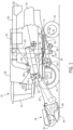
- an agricultural harvester in the form of a combine 10, which generally includes a chassis 12, ground engaging wheels 14 and 16, header 18, feeder housing 20, operator cab 22, threshing and separating system 24, cleaning system 26, grain tank 28, and unloading conveyor 30.
- Front wheels 14 are larger flotation type wheels, and rear wheels 16 are smaller steerable wheels. Motive force is selectively applied to front wheels 14 through a power plant in the form of a diesel engine 32 and a transmission (not shown). Although combine 10 is shown as including wheels, is also to be understood that combine 10 may include tracks.
- Header 18 is mounted to the front of combine 10 and includes a cutter bar 34 for severing crops from a field during forward motion of combine 10.
- a rotatable reel 36 feeds the crop into header 18, and a double auger 38 feeds the severed crop laterally inwardly from each side toward feeder housing 20.
- Feeder housing 20 conveys the cut crop to threshing and separating system 24, and is selectively vertically movable using appropriate actuators, such as hydraulic cylinders (not shown).
- Threshing and separating system 24 generally includes a rotor 40 at least partially enclosed by and rotatable within a corresponding perforated concave 42.
- the cut crops are threshed and separated by the rotation of rotor 40 within concave 42, and larger elements, such as stalks, leaves and the like are discharged from the rear of combine 10.
- Smaller elements of crop material including grain and non-grain crop material, including particles lighter than grain, such as chaff, dust and straw, are discharged through perforations of concave 42.
- Threshing and separating system 24 can also be a different type of system, such as a system with a transverse rotor rather than an axial rotor, etc.
- Cleaning system 26 may include an optional pre-cleaning sieve 46, an upper sieve 48 (also known as a chaffer sieve), a lower sieve 50 (also known as a cleaning sieve), and a cleaning fan 52.
- the upper sieve 48 and lower sieve 50 can be carried within a common framework. Grain on sieves 46, 48 and 50 is subjected to a cleaning action by fan 52 which provides an air flow through the sieves to remove chaff and other impurities such as dust from the grain by making this material airborne for discharge from straw hood 54 of combine 10.
- Grain pan 44 and pre-cleaning sieve 46 oscillate in a fore-to-aft manner to transport the grain and finer non-grain crop material to the upper surface of upper sieve 48.
- Upper sieve 48 and lower sieve 50 are vertically arranged relative to each other, and likewise oscillate in a fore-to-aft manner to spread the grain across sieves 48, 50, while permitting the passage of cleaned grain by gravity through the openings of sieves 48, 50.
- Clean grain falls to a clean grain auger 56 positioned crosswise below and toward the front of lower sieve 50.
- Clean grain auger 56 receives clean grain from each sieve 48, 50 and from bottom pan 58 of cleaning system 26.
- Clean grain auger 56 conveys the clean grain laterally to a generally vertically arranged grain elevator 60 for transport to grain tank 28.
- Tailings from cleaning system 26 fall to a tailings auger trough 62.
- the tailings are transported via tailings auger 64 and return auger 66 to the upstream end of cleaning system 26 for repeated cleaning action.
- a pair of grain tank augers 68 at the bottom of grain tank 28 convey the clean grain laterally within grain tank 28 to unloading conveyor 30 for discharge from combine 10.
- Unloading conveyor 30 may also be referred to in the art as an unload tube.
- FIG. 2 is a rear end view of the combine 10 of FIG. 1 showing grain unloading from unloading conveyor 30 of combine 10 into a truck 102.
- Unloading conveyor 30 is shown transversely extending and deployed outwardly in an unloading position as it unloads grain 70 through an unload spout 100 of conveyor 30 and into grain truck 102.
- This unloading operation can occur as combine 10 and truck 102 are moving, which is referred to as unloading "on the go", or the unloading operation can occur in a stationary manner.
- unloading conveyor 30 will be pivoted to a rearwardly directed transport position, extending along the adjacent side of combine 10.
- truck 102 is located a substantial distance to the side of combine 10, which is desired to avoid the possibility of contact with header 18 mounted on the front of combine 10, particularly when unloading on the go.
- conveyor 30, when in the unloading position illustrated will typically be tilted up toward the outer end thereof, at a greater angle, compared to when in the transport position, as additional height is often required to clear the top of the grain receptacle, here illustrated by truck 102.
- Unloading conveyor 30 includes an outer tube 300.
- outer tube 300 is not limited to a circular shape, and may take other shapes such as a square or rectangle.
- Outer tube 300 generally includes an elbow 302 that is rotatably mounted to a fixed mounting surface of combine, such as chassis 12 or grain tank 28.
- Elbow 302 is configured to rotate about axis 303 ( FIG. 2 ).
- a hollow elongated tube 304 is fixed to elbow 302 and rotates therewith about axis 303.
- the bottom surface of elbow 302 rests and rotates upon a stationary flange 401 that is positioned beneath elbow 302 of outer tube 300.
- Flange 401 is stationary with respect to the pivotable outer tube 300 and pivotable elbow 302. Flange 401 may or may not be considered as forming part of conveyor 30.
- One or more augers are positioned in tube 300 for transporting grain toward unload spout 100 that is mounted at the free end of conveyor 30.
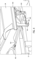
- Outer tube 300, including elbow 302, is omitted in FIG. 4 .
- An actuator 310 is mounted to elbow 302 for rotating elbow 302 (and the entire conveyor 30) about axis 303 between the stowed position ( FIGs. 1 and 3 ) and the deployed position ( FIG. 2 ).
- Actuator 310 may also be referred to in the art as a swing cylinder.
- Actuator 310 has a piston 311 and cylinder 312 arrangement, which piston 311 is translatably positioned within cylinder 312 and may be actuated either hydraulically, pneumatically, electrically or mechanically, for example. Actuator 310 is omitted in FIG. 4 .
- the exposed end of piston 311 includes an eyelet connector 315 that is connected to elbow 302 by a pin, for example.
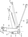
- One end of cylinder 312 includes a cylindrical mount 316 that is pinned to a mount 320 by a pin 322 such that cylinder 312 is capable of slight rotation with respect to mount 320 about the longitudinal axis 601 ( FIG. 6 ) of pin 322.
- Actuator 310 may be said to comprise a first end (in the form of a cylindrical mount 316) that is pivotably connected to mount 320, and a second end (in the form of eyelet connector 315) that is pivotably connected to elbow 302.
- Mount 320 is provided for supporting actuator 310.
- Mount 320 includes a series of interconnected frame members that connect to actuator 310 as well as grain tank 28, chassis 12 (or other fixed mounting point) on combine 10.
- Mount 320 may comprise a unitized cast body or individual components that are welded or fastened together.
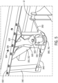
- Mount 320 includes a vertically oriented frame member 330 ( FIG. 6 ) that is fastened to a vertical surface of longitudinal beam 502 ( FIG. 5 ) of grain tank 28 (or chassis 12) by fasteners 504.
- Mount 320 also includes a horizontally oriented frame member 332 that is fastened to a horizontal surface of longitudinal beam 502 ( FIG. 5 ) of grain tank 28 (or chassis 12) by fasteners 504.
- a recess is formed between two flanges of mount 320 for accommodating the body of cylindrical mount 316.
- Mount 320 is additionally supported on combine 10 by three different rigid links 340, 350 and 360 that are connected to grain tank 28, chassis 12, and/or conveyor 30.
- the links extend in three different directions (e.g., x, y, and x-y directions of a Cartesian coordinate system), whereas the body of mount 320 extends in the z direction.
- Link 340 is a solid and rigid bar or rod extending in the X-direction and having (i) a first end 741 that is pinned to the bottom end of mount 320, and (ii) a second end 743 that is pinned to a bracket 342 that extends vertically downward from beam 502.
- the pins at ends 741 and 743 extend in the Y-direction such that each pinned end is capable of pivoting about the Y-axis.
- Link 350 is a solid and rigid bar or rod extending in the Y-direction and having (i) a first end 751 that is pinned to the bottom end of mount 320, and (ii) a second end 753 that is pinned to grain tank 28, chassis 12 (or other fixed mounting point on combine 10).
- the pins at ends 751 and 753 extend in the X-direction such that each pinned end is capable of pivoting about the X-axis.
- the pins at ends 751 and 753 extend orthogonally to the pins 741 and 743.
- Link 360 may also be referred to herein as a tension rod.
- Tension rod 360 is a solid bar or rod extending in the X-Y direction and having (i) a first end 761 that is pinned to the bottom end of mount 320 by pin 322 (i.e, the same pin that secures cylinder 312), and (ii) a second end 763 that is pinned to flange 401 ( FIG. 4 ).
- the flange 401 may also be referred to herein as a fixed tension rod mounting point.
- Tension rod 360 may extend parallel to cylinder 312.
- First end 761 of tension rod 360 comprises an eyelet connector that is positioned within a recess formed in mount 320 that is located beneath cylinder mount 316 of cylinder 312.
- First end 761 is capable of pivoting about axis 601.
- the pins at ends 761 and 763 extend in the Z-direction such that each pinned end is capable of pivoting about the Z-axis. Stated differently, the pins at ends 761 and 763 extend orthogonally to the pins 741 and 743 as well as pins 751 and 753.
- Tension rod 360 is mounted at an elevation below actuator 310.
- mount 320, and links 340, 350 and 360 may together constitute a mount assembly or swing cylinder mount. Additionally, mount 320, actuator 310 and links 340, 350 and 360 may together constitute an actuator assembly.
Landscapes
- Life Sciences & Earth Sciences (AREA)
- Environmental Sciences (AREA)
- Threshing Machine Elements (AREA)
Abstract
Description
- The present disclosure relates to a swing cylinder mount for an unload tube of an agricultural vehicle, such as a combine harvester.
- Agricultural vehicles, such as combine harvesters, commonly include an unload tube or unloading conveyor for distributing clean grain harvested by the combine harvester to another vehicle, such as the
truck 102 shown inFIG. 2 . An actuator is mounted to the unload tube for moving the tube from a stowed position, whereby the tube is positioned beside a grain tank of the combine harvester, to an extended or deployed position (seeFIG. 2 ) where the tube is extended from the combine harvester and the outlet of the tube is positioned for delivering the clean grain from the combine harvester to the other vehicle beside the combine harvester. Described herein is a mount for the aforementioned actuator that is optimized for load transfer, weight, cost, and serviceability. - An actuator assembly for moving an unload tube of an agricultural vehicle between stowed and deployed positions. The actuator assembly includes a mount that is configured to be fixed to a fixed mounting point on the agricultural vehicle. An actuator of the actuator assembly has a first end that is mounted to the mount and a second end that is mounted to the unload tube for moving the unload tube between the stowed and deployed positions. A tension rod of the actuator assembly has a first end that is pivotably mounted to the mount and a second end that is mounted to a fixed tension rod mounting point located either on or adjacent the unload tube.
- The above-mentioned and other features and advantages of this invention, and the manner of attaining them, will become more apparent and the invention will be better understood by reference to the following description of embodiments of the invention taken in conjunction with the accompanying drawings, wherein:
-
FIG. 1 is a side cutaway view of an embodiment of an agricultural harvester in the form of a combine, which is shown schematically. -
FIG. 2 is a rear end view of the combine ofFIG. 1 showing grain unloading from an unloading conveyor of the combine into a truck. -
FIG. 3 depicts an isometric detailed view of the combine ofFIG. 1 focusing on a region of the combine including a swing cylinder mount. -
FIGs. 4 and5 depict another isometric detailed view of the combine ofFIG. 1 . -
FIG. 6 and7 depict isometric views of the swing cylinder mount ofFIG. 3 . - Corresponding reference characters indicate corresponding parts throughout the several views. The exemplifications set out herein illustrate embodiments of the invention, and such exemplifications are not to be construed as limiting the scope of the invention in any manner.
- The terms "grain", "straw" and "tailings" are used principally throughout this specification for convenience but it is to be understood that these terms are not intended to be limiting. Thus "grain" refers to that part of the crop material which is threshed and separated from the discardable part of the crop material, which is referred to as non-grain crop material, MOG or straw. Incompletely threshed crop material is referred to as "tailings". Also the terms "forward", "rearward", "left" and "right", when used in connection with the agricultural harvester and/or components thereof are usually determined with reference to the direction of forward operative travel of the harvester, but again, they should not be construed as limiting. The terms "longitudinal" and "transverse" are determined with reference to the fore-and-aft direction of the agricultural harvester and are equally not to be construed as limiting.
- Referring now to the drawings, and more particularly to
FIG. 1 , there is shown an agricultural harvester in the form of acombine 10, which generally includes achassis 12, groundengaging wheels header 18,feeder housing 20,operator cab 22, threshing and separatingsystem 24,cleaning system 26,grain tank 28, and unloadingconveyor 30. -
Front wheels 14 are larger flotation type wheels, andrear wheels 16 are smaller steerable wheels. Motive force is selectively applied tofront wheels 14 through a power plant in the form of adiesel engine 32 and a transmission (not shown). Althoughcombine 10 is shown as including wheels, is also to be understood that combine 10 may include tracks. -
Header 18 is mounted to the front ofcombine 10 and includes acutter bar 34 for severing crops from a field during forward motion ofcombine 10. Arotatable reel 36 feeds the crop intoheader 18, and adouble auger 38 feeds the severed crop laterally inwardly from each side towardfeeder housing 20.Feeder housing 20 conveys the cut crop to threshing and separatingsystem 24, and is selectively vertically movable using appropriate actuators, such as hydraulic cylinders (not shown). - Threshing and separating
system 24 generally includes arotor 40 at least partially enclosed by and rotatable within a corresponding perforated concave 42. The cut crops are threshed and separated by the rotation ofrotor 40 within concave 42, and larger elements, such as stalks, leaves and the like are discharged from the rear ofcombine 10. Smaller elements of crop material including grain and non-grain crop material, including particles lighter than grain, such as chaff, dust and straw, are discharged through perforations of concave 42. Threshing and separatingsystem 24 can also be a different type of system, such as a system with a transverse rotor rather than an axial rotor, etc. - Grain which has been separated by the threshing and separating
assembly 24 falls onto agrain pan 44 and is conveyed towardcleaning system 26.Cleaning system 26 may include an optional pre-cleaningsieve 46, an upper sieve 48 (also known as a chaffer sieve), a lower sieve 50 (also known as a cleaning sieve), and acleaning fan 52. Theupper sieve 48 andlower sieve 50 can be carried within a common framework. Grain onsieves fan 52 which provides an air flow through the sieves to remove chaff and other impurities such as dust from the grain by making this material airborne for discharge fromstraw hood 54 of combine 10. Grainpan 44 and pre-cleaningsieve 46 oscillate in a fore-to-aft manner to transport the grain and finer non-grain crop material to the upper surface ofupper sieve 48.Upper sieve 48 andlower sieve 50 are vertically arranged relative to each other, and likewise oscillate in a fore-to-aft manner to spread the grain acrosssieves sieves - Clean grain falls to a
clean grain auger 56 positioned crosswise below and toward the front oflower sieve 50.Clean grain auger 56 receives clean grain from eachsieve bottom pan 58 ofcleaning system 26.Clean grain auger 56 conveys the clean grain laterally to a generally vertically arrangedgrain elevator 60 for transport tograin tank 28. Tailings fromcleaning system 26 fall to atailings auger trough 62. The tailings are transported viatailings auger 64 and returnauger 66 to the upstream end ofcleaning system 26 for repeated cleaning action. A pair ofgrain tank augers 68 at the bottom ofgrain tank 28 convey the clean grain laterally withingrain tank 28 to unloadingconveyor 30 for discharge fromcombine 10. Unloadingconveyor 30 may also be referred to in the art as an unload tube. -
FIG. 2 is a rear end view of thecombine 10 ofFIG. 1 showing grain unloading from unloadingconveyor 30 of combine 10 into atruck 102. Unloadingconveyor 30 is shown transversely extending and deployed outwardly in an unloading position as it unloadsgrain 70 through anunload spout 100 ofconveyor 30 and intograin truck 102. This unloading operation can occur as combine 10 andtruck 102 are moving, which is referred to as unloading "on the go", or the unloading operation can occur in a stationary manner. At the end of the unloading operation, unloadingconveyor 30 will be pivoted to a rearwardly directed transport position, extending along the adjacent side ofcombine 10. - Pivoting of unloading
conveyor 30 will be described in greater detail with reference toFIGs. 3-6 . It can be noted here thattruck 102 is located a substantial distance to the side ofcombine 10, which is desired to avoid the possibility of contact withheader 18 mounted on the front ofcombine 10, particularly when unloading on the go. It should also be noted thatconveyor 30, when in the unloading position illustrated, will typically be tilted up toward the outer end thereof, at a greater angle, compared to when in the transport position, as additional height is often required to clear the top of the grain receptacle, here illustrated bytruck 102. - Turning now to
FIG. 3 , that figure depicts unloadingconveyor 30 of combine 10 ofFIG. 1 . Unloadingconveyor 30 includes an outer tube 300. As viewed in cross-section, outer tube 300 is not limited to a circular shape, and may take other shapes such as a square or rectangle. Outer tube 300 generally includes anelbow 302 that is rotatably mounted to a fixed mounting surface of combine, such aschassis 12 orgrain tank 28. Elbow 302 is configured to rotate about axis 303 (FIG. 2 ). A hollow elongated tube 304 is fixed toelbow 302 and rotates therewith aboutaxis 303. The bottom surface ofelbow 302 rests and rotates upon astationary flange 401 that is positioned beneathelbow 302 of outer tube 300.Flange 401 is stationary with respect to the pivotable outer tube 300 andpivotable elbow 302.Flange 401 may or may not be considered as forming part ofconveyor 30. One or more augers (not shown) are positioned in tube 300 for transporting grain toward unloadspout 100 that is mounted at the free end ofconveyor 30. Outer tube 300, includingelbow 302, is omitted inFIG. 4 . - An actuator 310 is mounted to elbow 302 for rotating elbow 302 (and the entire conveyor 30) about
axis 303 between the stowed position (FIGs. 1 and3 ) and the deployed position (FIG. 2 ). Actuator 310 may also be referred to in the art as a swing cylinder. Actuator 310 has apiston 311 and cylinder 312 arrangement, whichpiston 311 is translatably positioned within cylinder 312 and may be actuated either hydraulically, pneumatically, electrically or mechanically, for example. Actuator 310 is omitted inFIG. 4 . - Turning now to
FIGs. 3-7 , the exposed end ofpiston 311 includes aneyelet connector 315 that is connected to elbow 302 by a pin, for example. One end of cylinder 312 includes acylindrical mount 316 that is pinned to amount 320 by apin 322 such that cylinder 312 is capable of slight rotation with respect to mount 320 about the longitudinal axis 601 (FIG. 6 ) ofpin 322. Actuator 310 may be said to comprise a first end (in the form of a cylindrical mount 316) that is pivotably connected to mount 320, and a second end (in the form of eyelet connector 315) that is pivotably connected toelbow 302. -
Mount 320 is provided for supporting actuator 310.Mount 320 includes a series of interconnected frame members that connect to actuator 310 as well asgrain tank 28, chassis 12 (or other fixed mounting point) oncombine 10.Mount 320 may comprise a unitized cast body or individual components that are welded or fastened together.Mount 320 includes a vertically oriented frame member 330 (FIG. 6 ) that is fastened to a vertical surface of longitudinal beam 502 (FIG. 5 ) of grain tank 28 (or chassis 12) byfasteners 504.Mount 320 also includes a horizontally orientedframe member 332 that is fastened to a horizontal surface of longitudinal beam 502 (FIG. 5 ) of grain tank 28 (or chassis 12) byfasteners 504. As best shown inFIG. 6 , a recess is formed between two flanges ofmount 320 for accommodating the body ofcylindrical mount 316. -
Mount 320 is additionally supported oncombine 10 by three differentrigid links grain tank 28,chassis 12, and/orconveyor 30. The links extend in three different directions (e.g., x, y, and x-y directions of a Cartesian coordinate system), whereas the body ofmount 320 extends in the z direction. -
Link 340 is a solid and rigid bar or rod extending in the X-direction and having (i) afirst end 741 that is pinned to the bottom end ofmount 320, and (ii) asecond end 743 that is pinned to abracket 342 that extends vertically downward frombeam 502. The pins at ends 741 and 743 extend in the Y-direction such that each pinned end is capable of pivoting about the Y-axis. -
Link 350 is a solid and rigid bar or rod extending in the Y-direction and having (i) afirst end 751 that is pinned to the bottom end ofmount 320, and (ii) asecond end 753 that is pinned tograin tank 28, chassis 12 (or other fixed mounting point on combine 10). The pins at ends 751 and 753 extend in the X-direction such that each pinned end is capable of pivoting about the X-axis. The pins at ends 751 and 753 extend orthogonally to thepins -
Link 360 may also be referred to herein as a tension rod.Tension rod 360 is a solid bar or rod extending in the X-Y direction and having (i) a first end 761 that is pinned to the bottom end ofmount 320 by pin 322 (i.e, the same pin that secures cylinder 312), and (ii) asecond end 763 that is pinned to flange 401 (FIG. 4 ). Theflange 401 may also be referred to herein as a fixed tension rod mounting point. -
Tension rod 360 may extend parallel to cylinder 312. First end 761 oftension rod 360 comprises an eyelet connector that is positioned within a recess formed inmount 320 that is located beneathcylinder mount 316 of cylinder 312. First end 761 is capable of pivoting aboutaxis 601. The pins at ends 761 and 763 extend in the Z-direction such that each pinned end is capable of pivoting about the Z-axis. Stated differently, the pins at ends 761 and 763 extend orthogonally to thepins pins Tension rod 360 is mounted at an elevation below actuator 310. - Considered together, mount 320, and links 340, 350 and 360 may together constitute a mount assembly or swing cylinder mount. Additionally, mount 320, actuator 310 and
links
Claims (15)
- An actuator assembly for moving an unload tube (30) of an agricultural vehicle (10) between stowed and deployed positions, said actuator assembly comprising:a mount (320) that is configured to be fixed to a fixed mounting point on the agricultural vehicle;an actuator (310) having a first end (316) that is mounted to the mount (320) and a second end (315) that is mounted to the unload tube (30) for moving the unload tube (30) between the stowed and deployed positions; characterized in that the actuator assembly further comprises:
a tension rod (360) having a first end (761) that is pivotably mounted to the mount (320) and a second end (763) that is mounted to a fixed tension rod mounting point (401) located either on or adjacent the unload tube (30). - The actuator assembly of claim 1, wherein the tension rod (360) and the actuator (310) are pivotably coupled to the mount (320).
- The actuator assembly of claim 2, wherein the tension rod (360) and the actuator (310) are pivotably coupled to the mount (320) about the same axis (601).
- The actuator assembly of claim 3, wherein the tension rod (360) and the actuator (310) are pinned to the mount (320) by the same pin (322).
- The actuator assembly of any one of the foregoing claims, wherein the fixed tension rod mounting point (401) is disposed on a stationary flange (401) that mates with the unload tube (30).
- The actuator assembly of any one of the foregoing claims, further comprising a first rigid link (340) having a first end that is pivotably connected to the mount (320) and a second end that is pivotably connected to another fixed mounting point (342) on the agricultural vehicle, and a second rigid link (350) having a first end that is pivotably connected to the mount (320) and a second end that is pivotably connected to yet another fixed mounting point (12) on the agricultural vehicle.
- The actuator assembly of claim 6, wherein the first rigid link (340) is pivotable relative to the mount (320) about a first axis, and the second rigid link (350) is pivotable relative to the mount (320) about a second axis that is orthogonal to the first axis.
- The actuator assembly of claim 7, wherein the tension rod (360) is pivotable relative to the mount (320) about a third axis that is orthogonal to the first and second axes.
- The actuator assembly of any one of the foregoing claims, wherein the tension rod (360) is pivotable relative to the mount (320) about an axis that is orthogonal to a longitudinal axis of the tension rod (360).
- The actuator assembly of any one of the foregoing claims, wherein the tension rod (360) is pivotable relative to the mount (320) about an axis that is orthogonal to an extension axis of the actuator (310).
- The actuator assembly of any one of the foregoing claims, wherein the mount (320) comprises a unitary component.
- The actuator assembly of any one of the foregoing claims, wherein the actuator (310) comprises a piston (311) that is translatable within a cylinder (312), and the piston (311) is configured to be actuated one of hydraulically, electrically, mechanically or pneumatically.
- An agricultural vehicle (10) comprising the actuator assembly of any one of the foregoing claims and the unload tube (30), wherein the actuator assembly is configured to rotate the unload tube (30) between the stowed and deployed positions.
- The agricultural vehicle of claim 13, wherein the agricultural vehicle (10) further comprises a clean grain storage tank (28), and the mount (320) is fixedly connected to the clean grain storage tank (28), and the unload tube (30) moves between the stowed position where the unload tube (30) is positioned beside the clean grain storage tank (28) and the deployed position where the unload tube (30) is positioned to extend outwardly from the clean grain storage tank (28).
- The agricultural vehicle of claim 13 or claim 14, wherein the agricultural vehicle (10) is a combine harvester.
Applications Claiming Priority (1)
| Application Number | Priority Date | Filing Date | Title |
|---|---|---|---|
| US18/228,926 US20250040482A1 (en) | 2023-08-01 | 2023-08-01 | Unload tube swing cylinder mount for agricultural vehicle |
Publications (1)
| Publication Number | Publication Date |
|---|---|
| EP4501098A1 true EP4501098A1 (en) | 2025-02-05 |
Family
ID=92212948
Family Applications (1)
| Application Number | Title | Priority Date | Filing Date |
|---|---|---|---|
| EP24192476.0A Pending EP4501098A1 (en) | 2023-08-01 | 2024-08-01 | Unload tube swing cylinder mount for agricultural vehicle |
Country Status (2)
| Country | Link |
|---|---|
| US (1) | US20250040482A1 (en) |
| EP (1) | EP4501098A1 (en) |
Citations (3)
| Publication number | Priority date | Publication date | Assignee | Title |
|---|---|---|---|---|
| US4459079A (en) * | 1979-07-23 | 1984-07-10 | Sperry Corporation | Unloading auger control system |
| EP3078253A1 (en) * | 2015-04-02 | 2016-10-12 | CNH Industrial Belgium nv | Improvements in or relating to crop unloading spouts |
| US20170367261A1 (en) * | 2015-11-20 | 2017-12-28 | Tribine Industries Llc | Rear Grain Cart Handling Assemblies For an Articulated Harvesting Combine |
Family Cites Families (4)
| Publication number | Priority date | Publication date | Assignee | Title |
|---|---|---|---|---|
| US3190423A (en) * | 1964-01-16 | 1965-06-22 | Case Co J I | Chute support for combine |
| US3638812A (en) * | 1970-04-07 | 1972-02-01 | Allis Chalmers Mfg Co | Tilting grain auger |
| US4332261A (en) * | 1980-09-24 | 1982-06-01 | Sperry Corporation | Automatic hydraulic neutralizing mechanism |
| US9215843B2 (en) * | 2012-03-26 | 2015-12-22 | Cnh Industrial America Llc | Conversion kit for automating foldable and unfoldable grain tank extensions of an agricultural combine |
-
2023
- 2023-08-01 US US18/228,926 patent/US20250040482A1/en active Pending
-
2024
- 2024-08-01 EP EP24192476.0A patent/EP4501098A1/en active Pending
Patent Citations (3)
| Publication number | Priority date | Publication date | Assignee | Title |
|---|---|---|---|---|
| US4459079A (en) * | 1979-07-23 | 1984-07-10 | Sperry Corporation | Unloading auger control system |
| EP3078253A1 (en) * | 2015-04-02 | 2016-10-12 | CNH Industrial Belgium nv | Improvements in or relating to crop unloading spouts |
| US20170367261A1 (en) * | 2015-11-20 | 2017-12-28 | Tribine Industries Llc | Rear Grain Cart Handling Assemblies For an Articulated Harvesting Combine |
Also Published As
| Publication number | Publication date |
|---|---|
| US20250040482A1 (en) | 2025-02-06 |
Similar Documents
| Publication | Publication Date | Title |
|---|---|---|
| US9992924B2 (en) | Folding mechanism for wide wheat headers | |
| US9554519B2 (en) | Agricultural harvester concave adjustment system and method | |
| US10080329B2 (en) | Side shaker link for agricultural harvester sieve assembly | |
| EP4491007A1 (en) | Unload spout for agricultural vehicle | |
| US10959379B2 (en) | Adjustable vanes for use in a cylindrical rotor cage of an agricultural harvester | |
| EP3275304B1 (en) | Lateral shake mechanism for agricultural harvester cleaner | |
| US9521808B2 (en) | Harvester chaff pan assembly with moveable deflector components | |
| US9308868B2 (en) | Access step for agricultural machine | |
| EP3120686B1 (en) | Linkage for agricultural harvester cleaner | |
| US20240023481A1 (en) | Integrated step-up within combine hitch | |
| US20250040482A1 (en) | Unload tube swing cylinder mount for agricultural vehicle | |
| EP3618603B1 (en) | Over-center locking system for a chaff pan of an agricultural harvester | |
| US12514164B2 (en) | Adjustment arrangement for a sieve in an agricultural harvester | |
| US20240373776A1 (en) | Position control of a segmented agricultural work assembly | |
| US12484483B2 (en) | Sieve installation arrangement in a cleaning system of an agricultural harvester | |
| US10058036B2 (en) | Structural members for a side shaking sieve arrangement in an agricultural harvester | |
| US9743573B2 (en) | Weight transfer and residue spreading apparatus for an agricultural vehicle | |
| US12588602B2 (en) | Unload tube lock for agricultural vehicle |
Legal Events
| Date | Code | Title | Description |
|---|---|---|---|
| PUAI | Public reference made under article 153(3) epc to a published international application that has entered the european phase |
Free format text: ORIGINAL CODE: 0009012 |
|
| STAA | Information on the status of an ep patent application or granted ep patent |
Free format text: STATUS: THE APPLICATION HAS BEEN PUBLISHED |
|
| AK | Designated contracting states |
Kind code of ref document: A1 Designated state(s): AL AT BE BG CH CY CZ DE DK EE ES FI FR GB GR HR HU IE IS IT LI LT LU LV MC ME MK MT NL NO PL PT RO RS SE SI SK SM TR |
|
| STAA | Information on the status of an ep patent application or granted ep patent |
Free format text: STATUS: REQUEST FOR EXAMINATION WAS MADE |
|
| STAA | Information on the status of an ep patent application or granted ep patent |
Free format text: STATUS: EXAMINATION IS IN PROGRESS |
|
| 17P | Request for examination filed |
Effective date: 20250805 |
|
| 17Q | First examination report despatched |
Effective date: 20250903 |