EP4498682A1 - Display device - Google Patents
Display device Download PDFInfo
- Publication number
- EP4498682A1 EP4498682A1 EP22933792.8A EP22933792A EP4498682A1 EP 4498682 A1 EP4498682 A1 EP 4498682A1 EP 22933792 A EP22933792 A EP 22933792A EP 4498682 A1 EP4498682 A1 EP 4498682A1
- Authority
- EP
- European Patent Office
- Prior art keywords
- layer
- transparency
- display device
- image
- display
- Prior art date
- Legal status (The legal status is an assumption and is not a legal conclusion. Google has not performed a legal analysis and makes no representation as to the accuracy of the status listed.)
- Pending
Links
Images







Classifications
-
- H—ELECTRICITY
- H04—ELECTRIC COMMUNICATION TECHNIQUE
- H04N—PICTORIAL COMMUNICATION, e.g. TELEVISION
- H04N21/00—Selective content distribution, e.g. interactive television or video on demand [VOD]
- H04N21/40—Client devices specifically adapted for the reception of or interaction with content, e.g. set-top-box [STB]; Operations thereof
- H04N21/47—End-user applications
- H04N21/485—End-user interface for client configuration
- H04N21/4854—End-user interface for client configuration for modifying image parameters, e.g. image brightness, contrast
-
- G—PHYSICS
- G06—COMPUTING OR CALCULATING; COUNTING
- G06F—ELECTRIC DIGITAL DATA PROCESSING
- G06F3/00—Input arrangements for transferring data to be processed into a form capable of being handled by the computer; Output arrangements for transferring data from processing unit to output unit, e.g. interface arrangements
- G06F3/01—Input arrangements or combined input and output arrangements for interaction between user and computer
- G06F3/048—Interaction techniques based on graphical user interfaces [GUI]
- G06F3/0481—Interaction techniques based on graphical user interfaces [GUI] based on specific properties of the displayed interaction object or a metaphor-based environment, e.g. interaction with desktop elements like windows or icons, or assisted by a cursor's changing behaviour or appearance
-
- H—ELECTRICITY
- H04—ELECTRIC COMMUNICATION TECHNIQUE
- H04N—PICTORIAL COMMUNICATION, e.g. TELEVISION
- H04N21/00—Selective content distribution, e.g. interactive television or video on demand [VOD]
- H04N21/40—Client devices specifically adapted for the reception of or interaction with content, e.g. set-top-box [STB]; Operations thereof
- H04N21/41—Structure of client; Structure of client peripherals
- H04N21/422—Input-only peripherals, i.e. input devices connected to specially adapted client devices, e.g. global positioning system [GPS]
- H04N21/42204—User interfaces specially adapted for controlling a client device through a remote control device; Remote control devices therefor
-
- H—ELECTRICITY
- H04—ELECTRIC COMMUNICATION TECHNIQUE
- H04N—PICTORIAL COMMUNICATION, e.g. TELEVISION
- H04N21/00—Selective content distribution, e.g. interactive television or video on demand [VOD]
- H04N21/40—Client devices specifically adapted for the reception of or interaction with content, e.g. set-top-box [STB]; Operations thereof
- H04N21/41—Structure of client; Structure of client peripherals
- H04N21/422—Input-only peripherals, i.e. input devices connected to specially adapted client devices, e.g. global positioning system [GPS]
- H04N21/42204—User interfaces specially adapted for controlling a client device through a remote control device; Remote control devices therefor
- H04N21/42206—User interfaces specially adapted for controlling a client device through a remote control device; Remote control devices therefor characterized by hardware details
- H04N21/4221—Dedicated function buttons, e.g. for the control of an EPG, subtitles, aspect ratio, picture-in-picture or teletext
-
- H—ELECTRICITY
- H04—ELECTRIC COMMUNICATION TECHNIQUE
- H04N—PICTORIAL COMMUNICATION, e.g. TELEVISION
- H04N21/00—Selective content distribution, e.g. interactive television or video on demand [VOD]
- H04N21/40—Client devices specifically adapted for the reception of or interaction with content, e.g. set-top-box [STB]; Operations thereof
- H04N21/43—Processing of content or additional data, e.g. demultiplexing additional data from a digital video stream; Elementary client operations, e.g. monitoring of home network or synchronising decoder's clock; Client middleware
- H04N21/431—Generation of visual interfaces for content selection or interaction; Content or additional data rendering
- H04N21/4312—Generation of visual interfaces for content selection or interaction; Content or additional data rendering involving specific graphical features, e.g. screen layout, special fonts or colors, blinking icons, highlights or animations
-
- H—ELECTRICITY
- H04—ELECTRIC COMMUNICATION TECHNIQUE
- H04N—PICTORIAL COMMUNICATION, e.g. TELEVISION
- H04N21/00—Selective content distribution, e.g. interactive television or video on demand [VOD]
- H04N21/40—Client devices specifically adapted for the reception of or interaction with content, e.g. set-top-box [STB]; Operations thereof
- H04N21/43—Processing of content or additional data, e.g. demultiplexing additional data from a digital video stream; Elementary client operations, e.g. monitoring of home network or synchronising decoder's clock; Client middleware
- H04N21/431—Generation of visual interfaces for content selection or interaction; Content or additional data rendering
- H04N21/4312—Generation of visual interfaces for content selection or interaction; Content or additional data rendering involving specific graphical features, e.g. screen layout, special fonts or colors, blinking icons, highlights or animations
- H04N21/4316—Generation of visual interfaces for content selection or interaction; Content or additional data rendering involving specific graphical features, e.g. screen layout, special fonts or colors, blinking icons, highlights or animations for displaying supplemental content in a region of the screen, e.g. an advertisement in a separate window
-
- H—ELECTRICITY
- H04—ELECTRIC COMMUNICATION TECHNIQUE
- H04N—PICTORIAL COMMUNICATION, e.g. TELEVISION
- H04N21/00—Selective content distribution, e.g. interactive television or video on demand [VOD]
- H04N21/40—Client devices specifically adapted for the reception of or interaction with content, e.g. set-top-box [STB]; Operations thereof
- H04N21/43—Processing of content or additional data, e.g. demultiplexing additional data from a digital video stream; Elementary client operations, e.g. monitoring of home network or synchronising decoder's clock; Client middleware
- H04N21/436—Interfacing a local distribution network, e.g. communicating with another STB or one or more peripheral devices inside the home
- H04N21/4363—Adapting the video stream to a specific local network, e.g. a Bluetooth® network
-
- H—ELECTRICITY
- H04—ELECTRIC COMMUNICATION TECHNIQUE
- H04N—PICTORIAL COMMUNICATION, e.g. TELEVISION
- H04N21/00—Selective content distribution, e.g. interactive television or video on demand [VOD]
- H04N21/40—Client devices specifically adapted for the reception of or interaction with content, e.g. set-top-box [STB]; Operations thereof
- H04N21/47—End-user applications
- H04N21/478—Supplemental services, e.g. displaying phone caller identification, shopping application
- H04N21/4782—Web browsing, e.g. WebTV
-
- H—ELECTRICITY
- H04—ELECTRIC COMMUNICATION TECHNIQUE
- H04N—PICTORIAL COMMUNICATION, e.g. TELEVISION
- H04N21/00—Selective content distribution, e.g. interactive television or video on demand [VOD]
- H04N21/40—Client devices specifically adapted for the reception of or interaction with content, e.g. set-top-box [STB]; Operations thereof
- H04N21/47—End-user applications
- H04N21/482—End-user interface for programme selection
-
- H—ELECTRICITY
- H04—ELECTRIC COMMUNICATION TECHNIQUE
- H04N—PICTORIAL COMMUNICATION, e.g. TELEVISION
- H04N21/00—Selective content distribution, e.g. interactive television or video on demand [VOD]
- H04N21/40—Client devices specifically adapted for the reception of or interaction with content, e.g. set-top-box [STB]; Operations thereof
- H04N21/47—End-user applications
- H04N21/485—End-user interface for client configuration
-
- H—ELECTRICITY
- H04—ELECTRIC COMMUNICATION TECHNIQUE
- H04N—PICTORIAL COMMUNICATION, e.g. TELEVISION
- H04N21/00—Selective content distribution, e.g. interactive television or video on demand [VOD]
- H04N21/40—Client devices specifically adapted for the reception of or interaction with content, e.g. set-top-box [STB]; Operations thereof
- H04N21/47—End-user applications
- H04N21/485—End-user interface for client configuration
- H04N21/4858—End-user interface for client configuration for modifying screen layout parameters, e.g. fonts, size of the windows
-
- H—ELECTRICITY
- H04—ELECTRIC COMMUNICATION TECHNIQUE
- H04N—PICTORIAL COMMUNICATION, e.g. TELEVISION
- H04N21/00—Selective content distribution, e.g. interactive television or video on demand [VOD]
- H04N21/40—Client devices specifically adapted for the reception of or interaction with content, e.g. set-top-box [STB]; Operations thereof
- H04N21/47—End-user applications
- H04N21/488—Data services, e.g. news ticker
- H04N21/4882—Data services, e.g. news ticker for displaying messages, e.g. warnings, reminders
-
- G—PHYSICS
- G06—COMPUTING OR CALCULATING; COUNTING
- G06F—ELECTRIC DIGITAL DATA PROCESSING
- G06F2203/00—Indexing scheme relating to G06F3/00 - G06F3/048
- G06F2203/048—Indexing scheme relating to G06F3/048
- G06F2203/04804—Transparency, e.g. transparent or translucent windows
Definitions
- the present disclosure relates to a display device, and more specifically, to a display device that can adjust the transparency of a display screen.
- Digital TV services using wired or wireless communication networks are becoming popular. Digital TV services can provide a variety of services that cannot be provided by existing analog broadcasting services.
- IPTV Internet Protocol Television
- smart TV service provide interactivity that allows users to actively select the type of program to watch and the viewing time.
- IPTV and smart TV services can provide various additional services, such as Internet search, home shopping, online games, and external device control, based on this interactivity.
- the technical problem of the present disclosure is to provide a display device that prevents viewing of a content image being played regardless of execution of an application or menu.
- the technical problem of this disclosure is to provide a seamless user experience between a display device and an application.
- a display device can comprise a display; a user input interface configured to receive signals from a remote control device; and a controller configured to: play a first content image on a first layer of the display, when a trigger for adjusting a transparency of a second layer higher than the first layer is occurred, activate a function of adjusting the transparency of the second layer according to the trigger, receive an input signal for adjusting the transparency of the second layer from the remote control device, and adjust the transparency of the second layer playing a second content according to the input signal.
- seamless switching between real-time broadcasting video and application execution video is possible through the wheel provided in the remote control device, so the user can check additional information about the alarm without interfering with viewing the real-time broadcasting video, thereby enjoying an improved user experience.
- a user can easily manipulate a content image played in a lower layer by adjusting transparency.
- the display device is, for example, an intelligent display device in which a computer support function is added to a broadcast reception function, and is faithful to a broadcast reception function and has an Internet function added thereto, such as a handwritten input device, a touch screen.
- a more user-friendly interface such as a spatial remote control may be provided.
- it is connected to the Internet and a computer with the support of a wired or wireless Internet function, so that functions such as e-mail, web browsing, banking, or games can also be performed.
- a standardized general-purpose OS may be used for these various functions.
- the display device may be, for example, a network TV, HBBTV, smart TV, LED TV, OLED TV, and the like, and may be applied to a smart phone in some cases.
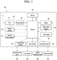
- FIG. 1 is a block diagram showing a configuration of a display device according to an embodiment of the present disclosure.
- a display device 100 may include a broadcast receiver 130, an external device interface 135, a memory 140, a user input interface 150, a controller 170, a wireless communication interface 173, a display 180, a speaker 185, and a power supply circuit 190.
- the broadcast receiver 130 may include a tuner 131, a demodulator 132, and a network interface 133.
- the tuner 131 may select a specific broadcast channel according to a channel selection command.
- the tuner 131 may receive a broadcast signal for the selected specific broadcast channel.
- the demodulator 132 may separate the received broadcast signal into an image signal, an audio signal, and a data signal related to a broadcast program, and restore the separated image signal, audio signal, and data signal to a format capable of being output.
- the external device interface 135 may receive an application or a list of applications in an external device adjacent thereto, and transmit the same to the controller 170 or the memory 140.
- the external device interface 135 may provide a connection path between the display device 100 and an external device.
- the external device interface 135 may receive one or more of images and audio output from an external device connected to the display device 100 in a wired or wireless manner, and transmit the same to the controller 170.
- the external device interface 135 may include a plurality of external input terminals.
- the plurality of external input terminals may include an RGB terminal, one or more High Definition Multimedia Interface (HDMI) terminals, and a component terminal.
- HDMI High Definition Multimedia Interface
- the image signal of the external device input through the external device interface 135 may be output through the display 180.
- the audio signal of the external device input through the external device interface 135 may be output through the speaker 185.
- the external device connectable to the external device interface 135 may be any one of a set-top box, a Blu-ray player, a DVD player, a game machine, a sound bar, a smartphone, a PC, a USB memory, and a home theater, but this is only an example.
- the network interface 133 may provide an interface for connecting the display device 100 to a wired/wireless network including an Internet network.
- the network interface 133 may transmit or receive data to or from other users or other electronic devices through a connected network or another network linked to the connected network.
- a part of content data stored in the display device 100 may be transmitted to a selected user among a selected user or a selected electronic device among other users or other electronic devices registered in advance in the display device 100.
- the network interface 133 may access a predetermined web page through the connected network or the other network linked to the connected network. That is, it is possible to access a predetermined web page through a network, and transmit or receive data to or from a corresponding server.
- the network interface 133 may receive content or data provided by a content provider or a network operator. That is, the network interface 133 may receive content such as movies, advertisements, games, VOD, and broadcast signals and information related thereto provided from a content provider or a network provider through a network.
- the network interface 133 may receive update information and update files of firmware provided by the network operator, and may transmit data to an Internet or content provider or a network operator.
- the network interface 133 may select and receive a desired application from among applications that are open to the public through a network.
- the memory 140 may store programs for signal processing and control of the controller 170, and may store images, audio, or data signals, which have been subjected to signal-processed.
- the memory 140 may perform a function for temporarily storing images, audio, or data signals input from an external device interface 135 or the network interface 133, and store information on a predetermined image through a channel storage function.
- the memory 140 may store an application or a list of applications input from the external device interface 135 or the network interface 133.
- the display device 100 may play back a content file (a moving image file, a still image file, a music file, a document file, an application file, or the like) stored in the memory 140 and provide the same to the user.
- a content file a moving image file, a still image file, a music file, a document file, an application file, or the like
- the user input interface 150 may transmit a signal input by the user to the controller 170 or a signal from the controller 170 to the user.
- the user input interface 150 may receive and process a control signal such as power on/off, channel selection, screen settings, and the like from the remote control device 200 in accordance with various communication methods, such as a Bluetooth communication method, a WB (Ultra Wideband) communication method, a ZigBee communication method, an RF (Radio Frequency) communication method, or an infrared (IR) communication method or may perform processing to transmit the control signal from the controller 170 to the remote control device 200.
- a Bluetooth communication method such as a Bluetooth communication method, a WB (Ultra Wideband) communication method, a ZigBee communication method, an RF (Radio Frequency) communication method, or an infrared (IR) communication method
- a Bluetooth communication method such as Bluetooth communication method, a WB (Ultra Wideband) communication method, a ZigBee communication method, an RF (Radio
- the user input interface 150 may transmit a control signal input from a local key (not shown) such as a power key, a channel key, a volume key, and a setting value to the controller 170.
- a local key such as a power key, a channel key, a volume key, and a setting value
- the image signal image-processed by the controller 170 may be input to the display 180 and displayed as an image corresponding to a corresponding image signal. Also, the image signal image-processed by the controller 170 may be input to an external output device through the external device interface 135.
- the audio signal processed by the controller 170 may be output to the speaker 185. Also, the audio signal processed by the controller 170 may be input to the external output device through the external device interface 135.
- controller 170 may control the overall operation of the display device 100.
- controller 170 may control the display device 100 by a user command input through the user input interface 150 or an internal program and connect to a network to download an application a list of applications or applications desired by the user to the display device 100.
- the controller 170 may allow the channel information or the like selected by the user to be output through the display 180 or the speaker 185 along with the processed image or audio signal.
- the controller 170 may output an image signal or an audio signal through the display 180 or the speaker 185, according to a command for playing back an image of an external device through the user input interface 150, the image signal or the audio signal being input from an external device, for example, a camera or a camcorder, through the external device interface 135.
- an external device for example, a camera or a camcorder
- the controller 170 may allow the display 180 to display an image, for example, allow a broadcast image which is input through the tuner 131 or an external input image which is input through the external device interface 135, an image which is input through the network interface or an image which is stored in the memory 140 to be displayed on the display 180.
- an image being displayed on the display 180 may be a still image or a moving image, and may be a 2D image or a 3D image.
- the controller 170 may allow content stored in the display device 100, received broadcast content, or external input content input from the outside to be played back, and the content may have various forms such as a broadcast image, an external input image, an audio file, still images, accessed web screens, and document files.
- the wireless communication interface 173 may communicate with an external device through wired or wireless communication.
- the wireless communication interface 173 may perform short range communication with an external device.
- the wireless communication interface 173 may support short range communication using at least one of Bluetooth TM , Radio Frequency Identification (RFID), Infrared Data Association (IrDA), Ultra Wideband (UWB), ZigBee, Near Field Communication (NFC), Wi-Fi (Wireless-Fidelity), Wi-Fi(Wireless-Fidelity), Wi-Fi Direct, and Wireless USB (Wireless Universal Serial Bus) technologies.
- RFID Radio Frequency Identification
- IrDA Infrared Data Association
- UWB Ultra Wideband
- ZigBee Near Field Communication
- NFC Near Field Communication
- Wi-Fi Wireless-Fidelity
- Wi-Fi Direct Wireless USB (Wireless Universal Serial Bus) technologies.
- the wireless communication interface 173 may support wireless communication between the display device 100 and a wireless communication system, between the display device 100 and another display device 100, or between the display device 100 and a network in which the display device 100 (or an external server) is located through wireless area networks.
- the wireless area networks may be wireless personal area networks.
- the another display device 100 may be a wearable device (e.g., a smartwatch, smart glasses or a head mounted display (HMD), a mobile terminal such as a smart phone, which is able to exchange data (or interwork) with the display device 100 according to the present disclosure.
- the wireless communication interface 173 may detect (or recognize) a wearable device capable of communication around the display device 100.
- the controller 170 may transmit at least a portion of data processed by the display device 100 to the wearable device through the wireless communication interface 173. Therefore, a user of the wearable device may use data processed by the display device 100 through the wearable device.
- the display 180 may convert image signals, data signals, and OSD signals processed by the controller 170, or image signals or data signals received from the external device interface 135 into R, G, and B signals, and generate drive signals.
- the display device 100 shown in FIG. 1 is only an embodiment of the present disclosure, some of the illustrated components may be integrated, added, or omitted depending on the specification of the display device 100 that is actually implemented.
- the display device 100 may receive an image through the network interface 133 or the external device interface 135 without a tuner 131 and a demodulator 132 and play back the same.
- the display device 100 may be divided into an image processing device, such as a set-top box, for receiving broadcast signals or content according to various network services, and a content playback device that plays back content input from the image processing device.
- an image processing device such as a set-top box
- a content playback device that plays back content input from the image processing device.
- an operation method of the display device according to an embodiment of the present disclosure will be described below may be implemented by not only the display device 100 as described with reference to FIG. 1 and but also one of an image processing device such as the separated set-top box and a content playback device including the display 180 and the speaker 185.
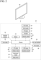
- FIG. 2 is a block diagram of a remote control device according to an embodiment of the present disclosure
- FIG. 3 shows an actual configuration example of a remote control device 200 according to an embodiment of the present disclosure.
- the remote control device 200 may include a fingerprint reader 210, a wireless communication circuit 220, a user input interface 230, a sensor 240, an output interface 250, a power supply circuit 260, a memory 270, a controller 280, and a microphone 290.
- the wireless communication circuit 220 may transmit and receive signals to and from any one of display devices according to embodiments of the present disclosure described above.
- the remote control device 200 may include an RF circuit 221 capable of transmitting and receiving signals to and from the display device 100 according to the RF communication standard, and an IR circuit 223 capable of transmitting and receiving signals to and from the display device 100 according to the IR communication standard.
- the remote control device 200 may include a Bluetooth circuit 225 capable of transmitting and receiving signals to and from the display device 100 according to the Bluetooth communication standard.
- the remote control device 200 may include an NFC circuit 227 capable of transmitting and receiving signals to and from the display device 100 according to the NFC (near field communication) communication standard, and a WLAN circuit 229 capable of transmitting and receiving signals to and from the display device 100 according to the wireless LAN (WLAN) communication standard.
- NFC near field communication
- WLAN wireless LAN
- the remote control device 200 may transmit a signal containing information on the movement of the remote control device 200 to the display device 100 through the wireless communication circuit 220.
- the remote control device 200 may receive a signal transmitted by the display device 100 through the RF circuit 221, and transmit a command regarding power on/off, channel change, volume adjustment, or the like to the display device 100 through the IR circuit 223 as necessary.
- the user input interface 230 may include a keypad, a button, a touch pad, a touch screen, or the like. The user may input a command related to the display device 100 to the remote control device 200 by operating the user input interface 230.
- the user input interface 230 includes a hard key button, the user may input a command related to the display device 100 to the remote control device 200 through a push operation of the hard key button. Details will be described with reference to FIG. 3 .
- the remote control device 200 may include a plurality of buttons.
- the plurality of buttons may include a fingerprint recognition button 212, a power button 231, a home button 232, a live button 233, an external input button 234, a volume control button 235, a voice recognition button 236, a channel change button 237, an OK button 238, and a back-play button 239.
- the fingerprint recognition button 212 may be a button for recognizing a user's fingerprint.
- the fingerprint recognition button 212 may enable a push operation, and thus may receive a push operation and a fingerprint recognition operation.
- the power button 231 may be a button for turning on/off the power of the display device 100.
- the home button 232 may be a button for moving to the home screen of the display device 100.
- the live button 233 may be a button for displaying a real-time broadcast program.
- the external input button 234 may be a button for receiving an external input connected to the display device 100.
- the volume control button 235 may be a button for adjusting the level of the volume output by the display device 100.
- the voice recognition button 236 may be a button for receiving a user's voice and recognizing the received voice.
- the channel change button 237 may be a button for receiving a broadcast signal of a specific broadcast channel.
- the OK button 238 may be a button for selecting a specific function, and the back-play button 239 may be a button for returning to a previous screen.
- the user input interface 230 When the user input interface 230 includes a touch screen, the user may input a command related to the display device 100 to the remote control device 200 by touching a soft key of the touch screen.
- the user input interface 230 may include various types of input means that may be operated by a user, such as a scroll key or a jog key, and the present embodiment does not limit the scope of the present disclosure.
- the sensor 240 may include a gyro sensor 241 or an acceleration sensor 243, and the gyro sensor 241 may sense information regarding the movement of the remote control device 200.
- the gyro sensor 241 may sense information about the operation of the remote control device 200 based on the x, y, and z axes, and the acceleration sensor 243 may sense information about the moving speed of the remote control device 200.
- the remote control device 200 may further include a distance measuring sensor to sense the distance between the display device 100 and the display 180.
- the output interface 250 may output an image or audio signal corresponding to the operation of the user input interface 230 or a signal transmitted from the display device 100.
- the user may recognize whether the user input interface 230 is operated or whether the display device 100 is controlled through the output interface 250.
- the output interface 450 may include an LED 251 that emits light, a vibrator 253 that generates vibration, a speaker 255 that outputs sound, or a display 257 that outputs an image when the user input interface 230 is operated or a signal is transmitted and received to and from the display device 100 through the wireless communication circuit 220.
- the power supply circuit 260 may supply power to the remote control device 200, and stop power supply when the remote control device 200 has not moved for a predetermined time to reduce power consumption.
- the power supply circuit 260 may restart power supply when a predetermined key provided in the remote control device 200 is operated.
- the memory 270 may store various types of programs and application data required for control or operation of the remote control device 200.
- the remote control device 200 transmits and receives signals wirelessly through the display device 100 and the RF circuit 221, the remote control device 200 and the display device 100 transmit and receive signals through a predetermined frequency band.
- the controller 280 of the remote control device 200 may store and refer to information on a frequency band capable of wirelessly transmitting and receiving signals to and from the display device 100 paired with the remote control device 200 in the memory 270.
- the controller 280 may control all matters related to the control of the remote control device 200.
- the controller 280 may transmit a signal corresponding to a predetermined key operation of the user input interface 230 or a signal corresponding to the movement of the remote control device 200 sensed by the sensor 240 through the wireless communication circuit 220.
- the microphone 290 of the remote control device 200 may obtain a speech.
- a plurality of microphones 290 may be provided.
- FIG. 4 shows an example of using a remote control device according to an embodiment of the present disclosure.
- FIG. 4 (a) illustrates that a pointer 205 corresponding to the remote control device 200 is displayed on the display 180.
- the user may move or rotate the remote control device 200 up, down, left and right.
- the pointer 205 displayed on the display 180 of the display device 100 may correspond to the movement of the remote control device 200.
- the pointer 205 is moved and displayed according to movement of the remote control device 200 in a 3D space, so the remote control device 200 may be called a space remote control device.
- the display device 100 may calculate the coordinates of the pointer 205 based on information on the movement of the remote control device 200.
- the display device 100 may display the pointer 205 to correspond to the calculated coordinates.
- (c) of FIG. 4 it is illustrated that a user moves the remote control device 200 away from the display 180 while pressing a specific button in the remote control device 200. Accordingly, a selected area in the display 180 corresponding to the pointer 205 may be zoomed in and displayed enlarged.
- the selected area in the display 180 corresponding to the pointer 205 may be zoomed out and displayed reduced.
- the selected area when the remote control device 200 moves away from the display 180, the selected area may be zoomed out, and when the remote control device 200 moves to be close to the display 180, the selected area may be zoomed in.
- recognition of up, down, left, or right movements may be excluded. That is, when the remote control device 200 moves away from or close to the display 180, the up, down, left, or right movements are not recognized, and only the forward and backward movements may be recognized. In a state in which a specific button in the remote control device 200 is not being pressed, only the pointer 205 moves according to the up, down, left, or right movements of the remote control device 200.
- the movement speed or the movement direction of the pointer 205 may correspond to the movement speed or the movement direction of the remote control device 200.
- a pointer refers to an object displayed on the display 180 in response to an operation of the remote control device 200. Accordingly, objects of various shapes other than the arrow shape shown in the drawings are possible as the pointer 205.
- the object may be a concept including a dot, a cursor, a prompt, a thick outline, and the like.
- the pointer 205 may be displayed corresponding to any one point among points on a horizontal axis and a vertical axis on the display 180, and may also be displayed corresponding to a plurality of points such as a line and a surface.
- Figure 5 is a diagram for explaining a layer structure of a display according to an embodiment of the present disclosure.
- the layers of the display 180 may include a card layer 510, an overlay layer 530, and a pop-up layer 550.
- the card layer 510 may include a first layer 511 and a second layer 513.
- the first layer 511 may be a layer for playing live broadcast video.
- the second layer 513 is a Peek layer and may be a layer for playing an execution video of an application.
- the first layer 511 may be a layer for executing a first application
- the second layer 513 may be a layer for executing a second application.
- the overlay layer (or a third layer, 530) may be a layer for providing a menu for setting the display device 100 or the display 180 or a menu for controlling an application.
- the pop-up layer (a fourth layer, 550) may be a layer for playing a pop-up window.
- the fourth layer 550 is the highest layer, and the third layer 530, second layer 513, and first layer 511 may follow in that order. That is, the first layer 511 may be the lowest layer.
- the transparency of only the second layer 513 among the first to fourth layers 511, 513, 530, and 550 can be adjusted.
- the transparency of the second layer 513 may be adjusted.
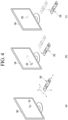
- Figure 6 is a diagram explaining an image output process of layers according to an embodiment of the present disclosure.
- the controller 170 may include an app management processor 610, an app execution processor 630, and a layer manager 650.
- the app management processor 610 may generate an app control signal to display the alarm of the application, and transmit the generated app control signal to the app execution processor 630.
- the app execution processor 630 may execute the application according to the received app control signal and transmit a playback command to the layer manager 650 to play the execution image of the application on the second layer 513.
- the layer manager 650 may transmit images to be output on each layer to the display 180 according to a playback control command including a playback command received from the app execution processor 630.
- the layer manager 650 may adjust the transparency of the second layer 513 or the transparency of the image played on the second layer 513 according to the input signal for transparency adjustment.
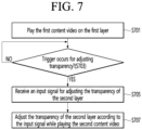
- FIG. 7 is a diagram illustrating a method of controlling transparency of a display device according to an embodiment of the present disclosure.
- the controller 170 of the display device 100 may display the first content image on the first layer 511 of the display 180 (S701).
- the first content image may be a broadcast image.
- the first content image may be a real-time broadcast image.
- the first content image may be a broadcast image provided through a live TV application for providing real-time broadcasting.
- FIG. 8 is a diagram illustrating an example of displaying a broadcast image on the first layer of a display according to an embodiment of the present disclosure.
- a real-time broadcast image 800 is displayed on the first layer 511 of the display 180.
- the controller 170 may control the display 180 so that the real-time broadcast image 800 is output on the first layer 511.
- a viewer is watching a broadcast video 800 through the display 180 of the display device 100.
- the controller 170 may determine whether a trigger for adjusting the transparency of the second layer 513 has occurred (703) .
- the controller 170 may determine that a trigger for adjusting the transparency of the second layer 513 has occurred.
- the alarm may be any one of a sports game progress (or result) alarm, a schedule alarm, or an alarm received from an IoT device linked to the display device 100.
- the controller 170 may determine that a trigger for adjusting the transparency of the second layer 513 has occurred.
- the controller 170 may determine that a trigger for adjusting the transparency of the second layer 513 has occurred.
- the controller 170 may receive an image for screen sharing from an external device through the wireless communication interface 173 and output it on the second layer 513.
- the controller 170 may determine that a trigger for adjusting the transparency of the second layer 513 has occurred at the time of outputting an image for screen sharing on the second layer 513.
- the controller 170 may output a notification indicating the occurrence of the trigger through the display 180 or speaker 185.
- Figure 9 is a diagram illustrating an example of displaying an alarm pop-up window while playing a real-time broadcast video according to an embodiment of the present disclosure.
- a real-time broadcast video 800 is being played on the first layer 511.
- the controller 170 may display a pop-up window 900 corresponding to the alarm on the fourth layer 550.
- the pop-up window 900 may appear to be displayed overlapping the real-time broadcast video 800.
- the controller 170 may determine that a trigger for adjusting the transparency of the second layer 513 has occurred.
- the controller 170 receives an input signal for adjusting the transparency of the second layer 513 (705).
- the controller 170 may receive an input signal for adjusting the transparency of the second layer 513 from the remote control device 200 through the user input interface 150.
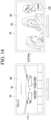
- the input signal for transparency control may be either an IR signal or a Bluetooth signal.
- the controller 170 may receive an input signal for transparency adjustment in the form of voice through a microphone (not shown) provided in the display device 100.
- the input signal for transparency adjustment may be a signal for adjusting the transparency of the second layer 513 to any one of 0% through 100% transparency.
- the user can adjust the transparency of the second layer 513 using the button or wheel provided on the remote control device 200.
- Figure 10 is a diagram for illustrating a method of adjusting transparency of a display according to an embodiment of the present disclosure.
- the remote control device 200 may include one or more of a first wheel 1010 and a second wheel 1030.
- the first wheel 1010 or the second wheel 1030 may be a physical component for adjusting the transparency of the second layer 513.
- the user can adjust the transparency of the second layer 513 by manipulating either the first wheel 1010 or the second wheel 1030.
- the user can adjust the transparency of the second layer 513 by raising or lowering either the first wheel 1010 or the second wheel 1030.
- transparency may increase as the wheel is raised, and transparency may decrease as the wheel is lowered.
- transparency may decrease as the wheel is raised, and transparency may increase as the wheel is lowered.
- the transparency of the second layer 513 can have a value from 0 to 100, and the user can control the display 180 to have any transparency from 0 to 100 through a wheel operation.
- the controller 170 may adjust the transparency of the second layer 513 that plays the second content image according to the received input signal (707).
- the display device 100 may receive an input signal according to the wheel operation from the remote control device 200 and adjust the transparency of the second layer 513 according to the received input signal.
- first and second content images may be displayed overlapping each other.
- FIGS. 11 to 13 are diagrams illustrating examples of viewing scenarios according to transparency adjustment of the second layer.
- a real-time broadcast video 800 is being played on the first layer 511 constituting the display 180, an execution image 1110 of an application is being played on the second layer 513, and the second layer 513 is playing a real-time broadcast video 800.
- a pop-up window 900 is playing on the fourth layer 900.
- controller 170 may display the application execution image 1110 on the second layer 513 as the pop-up window 900 is displayed on the fourth layer 550.
- the pop-up window 900 may be a window indicating a score alarm of a sports game.
- the controller 170 may recognize the received alarm as a trigger that can adjust the transparency of the second layer 513.
- the controller 170 may activate the transparency adjustment function of the second layer 513.
- the controller 170 may activate the transparency adjustment function of the second layer 513 when receiving a mirrored image for screen sharing (screen mirroring) from an external device. The mirroring image may be displayed on the second layer 513.
- the display device 100 when the display device 100 receives a scroll up signal to increase the wheel from the remote control device 200, the display device 100 may decrease the transparency of the second layer 513. Accordingly, the execution image 1110 of the application may be displayed overlapping with the real-time broadcast image 800.
- the controller 170 When the controller 170 receives a scroll up signal that adjusts transparency to 0, it can enter the application running on the second layer 513.
- the controller 170 may increase the transparency of the second layer 513.
- the display 180 may display only the broadcast image 800 being played on the first layer 511.
- the display device 100 can adjust the transparency of the application execution image 1110 being played on the second layer 513 according to a scroll up command or a scroll down command.
- seamless switching between the real-time broadcast image 800 and the application execution image 1110 is possible through the wheel provided in the remote control device 200.
- users can enjoy an improved user experience by being able to check additional information about the alarm without interfering with watching the real-time broadcast video.
- FIGS. 14 and 15 are diagrams illustrating an example of providing different menus depending on the properties (or type) of content played on the first layer when adjusting the transparency of the second layer.
- the display device 100 displays an execution image 1110 of an application being played on the second layer 513. It is assumed that the transparency of the second layer 513 is 0.
- the display device 100 may increase the transparency of the second layer 513 as it receives a scroll down command from the remote control device 200. As the transparency of the second layer 513 increases, the display device 100 may expose the real-time broadcast image 800 being played on the first layer 511.
- the display device 100 may display a menu for controlling content being played on the first layer 511.
- a menu for controlling content may be displayed on the third layer 530 or the first layer 511.
- the display device 100 may display a channel manipulation menu 1400 for controlling the real-time broadcast image being played on the first layer 511.
- the channel manipulation menu 1400 may be displayed when the transparency of the second layer 513 increases or when the transparency becomes 100.
- the channel manipulation menu 1400 may be displayed when the transparency of the second layer 513 is above a certain value.
- FIG. 15 assumes that an application execution image 1110 is being played on the second layer 513 and a web page image 1500 is being played on the first layer 511.
- the display device 100 may increase the transparency of the second layer 513 as it receives a scroll down command from the remote control device 200.
- the display device 100 may expose the web 800 being played on the first layer 511 as the transparency of the second layer 513 increases.
- the display device 100 may display a menu related to the web page image 1500 being played on the first layer 511.
- a menu related to the web page image 1500 may be displayed on the third layer 530 or the first layer 511.
- the display device 100 displays thumbnails 1510 and 1530 representing each of the web pages accessed before the web page 1500 being played on the first layer 511.
- the included web page menu 1500 can be displayed.
- the display device 100 may displays a favorites menu containing items indicating each of the web pages registered as favorites other than the web page 1500 being played on the first layer 511.
- the web page menu 1500 may be displayed when the transparency of the second layer 513 increases or when the transparency becomes 100.
- the web page menu 1500 may be displayed when the transparency of the second layer 513 is above a certain value.
- a menu for controlling the content or application being played on the first layer 511 may be displayed according to the transparency adjustment of the second layer 513.
- the user can easily control the content being played on the first layer 511, which is a lower layer, while watching the content image being played on the second layer 513.
- the above-described method can be implemented as processor-readable code on a program-recorded medium.
- media that the processor can read include ROM, RAM, CD-ROM, magnetic tape, floppy disk, and optical data storage devices.
- the display device described above is not limited to the configuration and method of the above-described embodiments, and the embodiments may be configured by selectively combining all or part of each embodiment so that various modifications can be made.
Landscapes
- Engineering & Computer Science (AREA)
- Multimedia (AREA)
- Signal Processing (AREA)
- Human Computer Interaction (AREA)
- Business, Economics & Management (AREA)
- Marketing (AREA)
- General Engineering & Computer Science (AREA)
- Theoretical Computer Science (AREA)
- Computer Networks & Wireless Communication (AREA)
- Physics & Mathematics (AREA)
- General Physics & Mathematics (AREA)
- Two-Way Televisions, Distribution Of Moving Picture Or The Like (AREA)
Abstract
Description
- The present disclosure relates to a display device, and more specifically, to a display device that can adjust the transparency of a display screen.
- Digital TV services using wired or wireless communication networks are becoming popular. Digital TV services can provide a variety of services that cannot be provided by existing analog broadcasting services.
- For example, IPTV (Internet Protocol Television), a type of digital TV service, and smart TV service provide interactivity that allows users to actively select the type of program to watch and the viewing time. IPTV and smart TV services can provide various additional services, such as Internet search, home shopping, online games, and external device control, based on this interactivity.
- In the past, viewing of a content video being played was interrupted during the process of executing and terminating an application or menu on a TV.
- Accordingly, there was a problem in which it was impossible to view content video while displaying alarm information, IoT device status information, or channel information, which are functions of a specific application.
- The technical problem of the present disclosure is to provide a display device that prevents viewing of a content image being played regardless of execution of an application or menu.
- The technical problem of this disclosure is to provide a seamless user experience between a display device and an application.
- According to an embodiment of the present invention, a display device can comprise a display; a user input interface configured to receive signals from a remote control device; and a controller configured to: play a first content image on a first layer of the display, when a trigger for adjusting a transparency of a second layer higher than the first layer is occurred, activate a function of adjusting the transparency of the second layer according to the trigger, receive an input signal for adjusting the transparency of the second layer from the remote control device, and adjust the transparency of the second layer playing a second content according to the input signal.
- According to an embodiment of the present disclosure, seamless switching between real-time broadcasting video and application execution video is possible through the wheel provided in the remote control device, so the user can check additional information about the alarm without interfering with viewing the real-time broadcasting video, thereby enjoying an improved user experience.
- According to an embodiment of the present disclosure, a user can easily manipulate a content image played in a lower layer by adjusting transparency.
-
-
FIG. 1 is a block diagram illustrating a configuration of a display device according to an embodiment of the present disclosure. -
FIG. 2 is a block diagram of a remote control device according to an embodiment of the present disclosure. -
FIG. 3 shows an example of an actual configuration of a remote control device according to an embodiment of the present disclosure. -
FIG. 4 shows an example of using a remote control device according to an embodiment of the present disclosure. -
Figure 5 is a diagram for explaining the layer structure of a display according to an embodiment of the present disclosure. -
Figure 6 is a diagram explaining the image output process of layers according to an embodiment of the present disclosure. -
FIG. 7 is a diagram illustrating a method of controlling transparency of a display device according to an embodiment of the present disclosure. -
FIG. 8 is a diagram illustrating an example of displaying a broadcast image on the first layer of a display according to an embodiment of the present disclosure. -
FIG. 9 is a diagram illustrating an example of displaying an alarm pop-up window while playing a real-time broadcast video according to an embodiment of the present disclosure. -
FIG. 10 is a diagram for explaining a method of adjusting transparency of a display according to an embodiment of the present disclosure. -
FIGS. 11 to 13 are diagrams illustrating examples of viewing scenarios according to transparency adjustment of the second layer. -
FIGS. 14 and15 are diagrams illustrating an example of providing different menus depending on the properties (or type) of content played on the first layer when adjusting the transparency of the second layer. - Hereinafter, embodiments of the present disclosure will be described in detail with reference to the drawings. The suffixes "module" and "unit or portion" for components used in the following description are merely provided only for facilitation of preparing this specification, and thus they are not granted a specific meaning or function.
- The display device according to an embodiment of the present disclosure is, for example, an intelligent display device in which a computer support function is added to a broadcast reception function, and is faithful to a broadcast reception function and has an Internet function added thereto, such as a handwritten input device, a touch screen. Alternatively, a more user-friendly interface such as a spatial remote control may be provided. In addition, it is connected to the Internet and a computer with the support of a wired or wireless Internet function, so that functions such as e-mail, web browsing, banking, or games can also be performed. A standardized general-purpose OS may be used for these various functions.
- Accordingly, in the display device described in the present disclosure, various user-friendly functions can be performed because various applications can be freely added or deleted, for example, on a general-purpose OS kernel. More specifically, the display device may be, for example, a network TV, HBBTV, smart TV, LED TV, OLED TV, and the like, and may be applied to a smart phone in some cases.
-
FIG. 1 is a block diagram showing a configuration of a display device according to an embodiment of the present disclosure. - Referring to
FIG. 1 , adisplay device 100 may include abroadcast receiver 130, anexternal device interface 135, amemory 140, auser input interface 150, acontroller 170, a wireless communication interface 173, adisplay 180, aspeaker 185, and apower supply circuit 190. - The
broadcast receiver 130 may include atuner 131, ademodulator 132, and anetwork interface 133. - The
tuner 131 may select a specific broadcast channel according to a channel selection command. Thetuner 131 may receive a broadcast signal for the selected specific broadcast channel. - The
demodulator 132 may separate the received broadcast signal into an image signal, an audio signal, and a data signal related to a broadcast program, and restore the separated image signal, audio signal, and data signal to a format capable of being output. - The
external device interface 135 may receive an application or a list of applications in an external device adjacent thereto, and transmit the same to thecontroller 170 or thememory 140. - The
external device interface 135 may provide a connection path between thedisplay device 100 and an external device. Theexternal device interface 135 may receive one or more of images and audio output from an external device connected to thedisplay device 100 in a wired or wireless manner, and transmit the same to thecontroller 170. Theexternal device interface 135 may include a plurality of external input terminals. The plurality of external input terminals may include an RGB terminal, one or more High Definition Multimedia Interface (HDMI) terminals, and a component terminal. - The image signal of the external device input through the
external device interface 135 may be output through thedisplay 180. The audio signal of the external device input through theexternal device interface 135 may be output through thespeaker 185. - The external device connectable to the
external device interface 135 may be any one of a set-top box, a Blu-ray player, a DVD player, a game machine, a sound bar, a smartphone, a PC, a USB memory, and a home theater, but this is only an example. - The
network interface 133 may provide an interface for connecting thedisplay device 100 to a wired/wireless network including an Internet network. Thenetwork interface 133 may transmit or receive data to or from other users or other electronic devices through a connected network or another network linked to the connected network. - In addition, a part of content data stored in the
display device 100 may be transmitted to a selected user among a selected user or a selected electronic device among other users or other electronic devices registered in advance in thedisplay device 100. - The
network interface 133 may access a predetermined web page through the connected network or the other network linked to the connected network. That is, it is possible to access a predetermined web page through a network, and transmit or receive data to or from a corresponding server. - In addition, the
network interface 133 may receive content or data provided by a content provider or a network operator. That is, thenetwork interface 133 may receive content such as movies, advertisements, games, VOD, and broadcast signals and information related thereto provided from a content provider or a network provider through a network. - In addition, the
network interface 133 may receive update information and update files of firmware provided by the network operator, and may transmit data to an Internet or content provider or a network operator. - The
network interface 133 may select and receive a desired application from among applications that are open to the public through a network. - The
memory 140 may store programs for signal processing and control of thecontroller 170, and may store images, audio, or data signals, which have been subjected to signal-processed. - In addition, the
memory 140 may perform a function for temporarily storing images, audio, or data signals input from anexternal device interface 135 or thenetwork interface 133, and store information on a predetermined image through a channel storage function. - The
memory 140 may store an application or a list of applications input from theexternal device interface 135 or thenetwork interface 133. - The
display device 100 may play back a content file (a moving image file, a still image file, a music file, a document file, an application file, or the like) stored in thememory 140 and provide the same to the user. - The
user input interface 150 may transmit a signal input by the user to thecontroller 170 or a signal from thecontroller 170 to the user. For example, theuser input interface 150 may receive and process a control signal such as power on/off, channel selection, screen settings, and the like from theremote control device 200 in accordance with various communication methods, such as a Bluetooth communication method, a WB (Ultra Wideband) communication method, a ZigBee communication method, an RF (Radio Frequency) communication method, or an infrared (IR) communication method or may perform processing to transmit the control signal from thecontroller 170 to theremote control device 200. - In addition, the
user input interface 150 may transmit a control signal input from a local key (not shown) such as a power key, a channel key, a volume key, and a setting value to thecontroller 170. - The image signal image-processed by the
controller 170 may be input to thedisplay 180 and displayed as an image corresponding to a corresponding image signal. Also, the image signal image-processed by thecontroller 170 may be input to an external output device through theexternal device interface 135. - The audio signal processed by the
controller 170 may be output to thespeaker 185. Also, the audio signal processed by thecontroller 170 may be input to the external output device through theexternal device interface 135. - In addition, the
controller 170 may control the overall operation of thedisplay device 100. - In addition, the
controller 170 may control thedisplay device 100 by a user command input through theuser input interface 150 or an internal program and connect to a network to download an application a list of applications or applications desired by the user to thedisplay device 100. - The
controller 170 may allow the channel information or the like selected by the user to be output through thedisplay 180 or thespeaker 185 along with the processed image or audio signal. - In addition, the
controller 170 may output an image signal or an audio signal through thedisplay 180 or thespeaker 185, according to a command for playing back an image of an external device through theuser input interface 150, the image signal or the audio signal being input from an external device, for example, a camera or a camcorder, through theexternal device interface 135. - Meanwhile, the
controller 170 may allow thedisplay 180 to display an image, for example, allow a broadcast image which is input through thetuner 131 or an external input image which is input through theexternal device interface 135, an image which is input through the network interface or an image which is stored in thememory 140 to be displayed on thedisplay 180. In this case, an image being displayed on thedisplay 180 may be a still image or a moving image, and may be a 2D image or a 3D image. - In addition, the
controller 170 may allow content stored in thedisplay device 100, received broadcast content, or external input content input from the outside to be played back, and the content may have various forms such as a broadcast image, an external input image, an audio file, still images, accessed web screens, and document files. - The wireless communication interface 173 may communicate with an external device through wired or wireless communication. The wireless communication interface 173 may perform short range communication with an external device. To this end, the wireless communication interface 173 may support short range communication using at least one of Bluetooth™, Radio Frequency Identification (RFID), Infrared Data Association (IrDA), Ultra Wideband (UWB), ZigBee, Near Field Communication (NFC), Wi-Fi (Wireless-Fidelity), Wi-Fi(Wireless-Fidelity), Wi-Fi Direct, and Wireless USB (Wireless Universal Serial Bus) technologies. The wireless communication interface 173 may support wireless communication between the
display device 100 and a wireless communication system, between thedisplay device 100 and anotherdisplay device 100, or between thedisplay device 100 and a network in which the display device 100 (or an external server) is located through wireless area networks. The wireless area networks may be wireless personal area networks. - Here, the another
display device 100 may be a wearable device (e.g., a smartwatch, smart glasses or a head mounted display (HMD), a mobile terminal such as a smart phone, which is able to exchange data (or interwork) with thedisplay device 100 according to the present disclosure. The wireless communication interface 173 may detect (or recognize) a wearable device capable of communication around thedisplay device 100. - Furthermore, when the detected wearable device is an authenticated device to communicate with the
display device 100 according to the present disclosure, thecontroller 170 may transmit at least a portion of data processed by thedisplay device 100 to the wearable device through the wireless communication interface 173. Therefore, a user of the wearable device may use data processed by thedisplay device 100 through the wearable device. - The
display 180 may convert image signals, data signals, and OSD signals processed by thecontroller 170, or image signals or data signals received from theexternal device interface 135 into R, G, and B signals, and generate drive signals. - Meanwhile, since the
display device 100 shown inFIG. 1 is only an embodiment of the present disclosure, some of the illustrated components may be integrated, added, or omitted depending on the specification of thedisplay device 100 that is actually implemented. - That is, two or more components may be combined into one component, or one component may be divided into two or more components as necessary. In addition, a function performed in each block is for describing an embodiment of the present disclosure, and its specific operation or device does not limit the scope of the present disclosure.
- According to another embodiment of the present disclosure, unlike the
display device 100 shown inFIG. 1 , thedisplay device 100 may receive an image through thenetwork interface 133 or theexternal device interface 135 without atuner 131 and ademodulator 132 and play back the same. - For example, the
display device 100 may be divided into an image processing device, such as a set-top box, for receiving broadcast signals or content according to various network services, and a content playback device that plays back content input from the image processing device. - In this case, an operation method of the display device according to an embodiment of the present disclosure will be described below may be implemented by not only the
display device 100 as described with reference toFIG. 1 and but also one of an image processing device such as the separated set-top box and a content playback device including thedisplay 180 and thespeaker 185. - Next, a remote control device according to an embodiment of the present disclosure will be described with reference to
FIGS. 2 to 3 . -
FIG. 2 is a block diagram of a remote control device according to an embodiment of the present disclosure, andFIG. 3 shows an actual configuration example of aremote control device 200 according to an embodiment of the present disclosure. - First, referring to
FIG. 2 , theremote control device 200 may include afingerprint reader 210, awireless communication circuit 220, auser input interface 230, asensor 240, anoutput interface 250, apower supply circuit 260, amemory 270, acontroller 280, and amicrophone 290. - Referring to
FIG. 2 , thewireless communication circuit 220 may transmit and receive signals to and from any one of display devices according to embodiments of the present disclosure described above. - The
remote control device 200 may include anRF circuit 221 capable of transmitting and receiving signals to and from thedisplay device 100 according to the RF communication standard, and an IR circuit 223 capable of transmitting and receiving signals to and from thedisplay device 100 according to the IR communication standard. In addition, theremote control device 200 may include aBluetooth circuit 225 capable of transmitting and receiving signals to and from thedisplay device 100 according to the Bluetooth communication standard. In addition, theremote control device 200 may include anNFC circuit 227 capable of transmitting and receiving signals to and from thedisplay device 100 according to the NFC (near field communication) communication standard, and aWLAN circuit 229 capable of transmitting and receiving signals to and from thedisplay device 100 according to the wireless LAN (WLAN) communication standard. - In addition, the
remote control device 200 may transmit a signal containing information on the movement of theremote control device 200 to thedisplay device 100 through thewireless communication circuit 220. - In addition, the
remote control device 200 may receive a signal transmitted by thedisplay device 100 through theRF circuit 221, and transmit a command regarding power on/off, channel change, volume adjustment, or the like to thedisplay device 100 through the IR circuit 223 as necessary. - The
user input interface 230 may include a keypad, a button, a touch pad, a touch screen, or the like. The user may input a command related to thedisplay device 100 to theremote control device 200 by operating theuser input interface 230. When theuser input interface 230 includes a hard key button, the user may input a command related to thedisplay device 100 to theremote control device 200 through a push operation of the hard key button. Details will be described with reference toFIG. 3 . - Referring to
FIG. 3 , theremote control device 200 may include a plurality of buttons. The plurality of buttons may include afingerprint recognition button 212, apower button 231, ahome button 232, alive button 233, anexternal input button 234, avolume control button 235, avoice recognition button 236, achannel change button 237, anOK button 238, and a back-play button 239. - The
fingerprint recognition button 212 may be a button for recognizing a user's fingerprint. In one embodiment, thefingerprint recognition button 212 may enable a push operation, and thus may receive a push operation and a fingerprint recognition operation. - The
power button 231 may be a button for turning on/off the power of thedisplay device 100. - The
home button 232 may be a button for moving to the home screen of thedisplay device 100. - The
live button 233 may be a button for displaying a real-time broadcast program. - The
external input button 234 may be a button for receiving an external input connected to thedisplay device 100. - The
volume control button 235 may be a button for adjusting the level of the volume output by thedisplay device 100. - The
voice recognition button 236 may be a button for receiving a user's voice and recognizing the received voice. - The
channel change button 237 may be a button for receiving a broadcast signal of a specific broadcast channel. - The
OK button 238 may be a button for selecting a specific function, and the back-play button 239 may be a button for returning to a previous screen. - A description will be given referring again to
FIG. 2 . - When the
user input interface 230 includes a touch screen, the user may input a command related to thedisplay device 100 to theremote control device 200 by touching a soft key of the touch screen. In addition, theuser input interface 230 may include various types of input means that may be operated by a user, such as a scroll key or a jog key, and the present embodiment does not limit the scope of the present disclosure. - The
sensor 240 may include agyro sensor 241 or anacceleration sensor 243, and thegyro sensor 241 may sense information regarding the movement of theremote control device 200. - For example, the
gyro sensor 241 may sense information about the operation of theremote control device 200 based on the x, y, and z axes, and theacceleration sensor 243 may sense information about the moving speed of theremote control device 200. Meanwhile, theremote control device 200 may further include a distance measuring sensor to sense the distance between thedisplay device 100 and thedisplay 180. - The
output interface 250 may output an image or audio signal corresponding to the operation of theuser input interface 230 or a signal transmitted from thedisplay device 100. - The user may recognize whether the
user input interface 230 is operated or whether thedisplay device 100 is controlled through theoutput interface 250. - For example, the output interface 450 may include an
LED 251 that emits light, avibrator 253 that generates vibration, aspeaker 255 that outputs sound, or adisplay 257 that outputs an image when theuser input interface 230 is operated or a signal is transmitted and received to and from thedisplay device 100 through thewireless communication circuit 220. - In addition, the
power supply circuit 260 may supply power to theremote control device 200, and stop power supply when theremote control device 200 has not moved for a predetermined time to reduce power consumption. - The
power supply circuit 260 may restart power supply when a predetermined key provided in theremote control device 200 is operated. - The
memory 270 may store various types of programs and application data required for control or operation of theremote control device 200. - When the
remote control device 200 transmits and receives signals wirelessly through thedisplay device 100 and theRF circuit 221, theremote control device 200 and thedisplay device 100 transmit and receive signals through a predetermined frequency band. - The
controller 280 of theremote control device 200 may store and refer to information on a frequency band capable of wirelessly transmitting and receiving signals to and from thedisplay device 100 paired with theremote control device 200 in thememory 270. - The
controller 280 may control all matters related to the control of theremote control device 200. Thecontroller 280 may transmit a signal corresponding to a predetermined key operation of theuser input interface 230 or a signal corresponding to the movement of theremote control device 200 sensed by thesensor 240 through thewireless communication circuit 220. - Also, the
microphone 290 of theremote control device 200 may obtain a speech. - A plurality of
microphones 290 may be provided. - Next, a description will be given referring to
FIG. 4 . -
FIG. 4 shows an example of using a remote control device according to an embodiment of the present disclosure. - In
FIG. 4, (a) illustrates that apointer 205 corresponding to theremote control device 200 is displayed on thedisplay 180. - The user may move or rotate the
remote control device 200 up, down, left and right. Thepointer 205 displayed on thedisplay 180 of thedisplay device 100 may correspond to the movement of theremote control device 200. As shown in the drawings, thepointer 205 is moved and displayed according to movement of theremote control device 200 in a 3D space, so theremote control device 200 may be called a space remote control device. - In (b) of
FIG. 4 , it is illustrated that that when the user moves theremote control device 200 to the left, thepointer 205 displayed on thedisplay 180 of thedisplay device 100 moves to the left correspondingly. - Information on the movement of the
remote control device 200 detected through a sensor of theremote control device 200 is transmitted to thedisplay device 100. Thedisplay device 100 may calculate the coordinates of thepointer 205 based on information on the movement of theremote control device 200. Thedisplay device 100 may display thepointer 205 to correspond to the calculated coordinates. - In (c) of
FIG. 4 , it is illustrated that a user moves theremote control device 200 away from thedisplay 180 while pressing a specific button in theremote control device 200. Accordingly, a selected area in thedisplay 180 corresponding to thepointer 205 may be zoomed in and displayed enlarged. - Conversely, when the user moves the
remote control device 200 to be close to thedisplay 180, the selected area in thedisplay 180 corresponding to thepointer 205 may be zoomed out and displayed reduced. - On the other hand, when the
remote control device 200 moves away from thedisplay 180, the selected area may be zoomed out, and when theremote control device 200 moves to be close to thedisplay 180, the selected area may be zoomed in. - Also, in a state in which a specific button in the
remote control device 200 is being pressed, recognition of up, down, left, or right movements may be excluded. That is, when theremote control device 200 moves away from or close to thedisplay 180, the up, down, left, or right movements are not recognized, and only the forward and backward movements may be recognized. In a state in which a specific button in theremote control device 200 is not being pressed, only thepointer 205 moves according to the up, down, left, or right movements of theremote control device 200. - Meanwhile, the movement speed or the movement direction of the
pointer 205 may correspond to the movement speed or the movement direction of theremote control device 200. - Meanwhile, in the present specification, a pointer refers to an object displayed on the
display 180 in response to an operation of theremote control device 200. Accordingly, objects of various shapes other than the arrow shape shown in the drawings are possible as thepointer 205. For example, the object may be a concept including a dot, a cursor, a prompt, a thick outline, and the like. In addition, thepointer 205 may be displayed corresponding to any one point among points on a horizontal axis and a vertical axis on thedisplay 180, and may also be displayed corresponding to a plurality of points such as a line and a surface. -
Figure 5 is a diagram for explaining a layer structure of a display according to an embodiment of the present disclosure. - Referring to
FIG. 5 , the layers of thedisplay 180 may include acard layer 510, anoverlay layer 530, and a pop-uplayer 550. - The
card layer 510 may include afirst layer 511 and asecond layer 513. - The
first layer 511 may be a layer for playing live broadcast video. - The
second layer 513 is a Peek layer and may be a layer for playing an execution video of an application. - As another example, the
first layer 511 may be a layer for executing a first application, and thesecond layer 513 may be a layer for executing a second application. - The overlay layer (or a third layer, 530) may be a layer for providing a menu for setting the
display device 100 or thedisplay 180 or a menu for controlling an application. - The pop-up layer (a fourth layer, 550) may be a layer for playing a pop-up window.
- The
fourth layer 550 is the highest layer, and thethird layer 530,second layer 513, andfirst layer 511 may follow in that order. That is, thefirst layer 511 may be the lowest layer. - In one embodiment, the transparency of only the
second layer 513 among the first tofourth layers - Hereinafter, the description will be made assuming that only the
second layer 513 can have transparency adjusted. - As the transparency of the
second layer 513 is adjusted, the transparency of the content image displayed on thesecond layer 513 may be adjusted. -
Figure 6 is a diagram explaining an image output process of layers according to an embodiment of the present disclosure. - Referring to
FIG. 6 , thecontroller 170 may include anapp management processor 610, anapp execution processor 630, and alayer manager 650. - When receiving an alarm of an application, the
app management processor 610 may generate an app control signal to display the alarm of the application, and transmit the generated app control signal to theapp execution processor 630. - The
app execution processor 630 may execute the application according to the received app control signal and transmit a playback command to thelayer manager 650 to play the execution image of the application on thesecond layer 513. - The
layer manager 650 may transmit images to be output on each layer to thedisplay 180 according to a playback control command including a playback command received from theapp execution processor 630. - The
layer manager 650 may adjust the transparency of thesecond layer 513 or the transparency of the image played on thesecond layer 513 according to the input signal for transparency adjustment. -
FIG. 7 is a diagram illustrating a method of controlling transparency of a display device according to an embodiment of the present disclosure. - Referring to
FIG. 7 , thecontroller 170 of thedisplay device 100 may display the first content image on thefirst layer 511 of the display 180 (S701). - In one embodiment, the first content image may be a broadcast image. Specifically, the first content image may be a real-time broadcast image.
- The first content image may be a broadcast image provided through a live TV application for providing real-time broadcasting.
-
FIG. 8 is a diagram illustrating an example of displaying a broadcast image on the first layer of a display according to an embodiment of the present disclosure. - Referring to
FIG. 8 , a real-time broadcast image 800 is displayed on thefirst layer 511 of thedisplay 180. - When receiving the real-
time broadcast image 800, thecontroller 170 may control thedisplay 180 so that the real-time broadcast image 800 is output on thefirst layer 511. - That is, there may be a situation in which no image is played on the
second layer 513,third layer 530, andfourth layer 550. - A viewer is watching a
broadcast video 800 through thedisplay 180 of thedisplay device 100. - Again,
Figure 7 will be described. - The
controller 170 may determine whether a trigger for adjusting the transparency of thesecond layer 513 has occurred (703) . - In one embodiment, when an alarm is received while playing the first content image, the
controller 170 may determine that a trigger for adjusting the transparency of thesecond layer 513 has occurred. - Here, the alarm may be any one of a sports game progress (or result) alarm, a schedule alarm, or an alarm received from an IoT device linked to the
display device 100. - In another embodiment, when an alarm pop-up window corresponding to an alarm is displayed on the
fourth layer 550, thecontroller 170 may determine that a trigger for adjusting the transparency of thesecond layer 513 has occurred. - In another embodiment, when receiving an image for screen sharing from an external device, the
controller 170 may determine that a trigger for adjusting the transparency of thesecond layer 513 has occurred. - The
controller 170 may receive an image for screen sharing from an external device through the wireless communication interface 173 and output it on thesecond layer 513. Thecontroller 170 may determine that a trigger for adjusting the transparency of thesecond layer 513 has occurred at the time of outputting an image for screen sharing on thesecond layer 513. - When a trigger for adjusting the transparency of the
second layer 513 occurs, thecontroller 170 may output a notification indicating the occurrence of the trigger through thedisplay 180 orspeaker 185. -
Figure 9 is a diagram illustrating an example of displaying an alarm pop-up window while playing a real-time broadcast video according to an embodiment of the present disclosure. - Referring to
FIG. 9 , a real-time broadcast video 800 is being played on thefirst layer 511. - If an alarm occurs while playing the real-
time broadcast video 800, thecontroller 170 may display a pop-upwindow 900 corresponding to the alarm on thefourth layer 550. - From a viewer's perspective, the pop-up
window 900 may appear to be displayed overlapping the real-time broadcast video 800. - When an alarm is generated or a pop-up
window 900 is displayed on thefourth layer 550, thecontroller 170 may determine that a trigger for adjusting the transparency of thesecond layer 513 has occurred. - Again,
Figure 7 will be described. - When a trigger for adjusting the transparency of the
second layer 513 occurs, thecontroller 170 receives an input signal for adjusting the transparency of the second layer 513 (705). - In one embodiment, the
controller 170 may receive an input signal for adjusting the transparency of thesecond layer 513 from theremote control device 200 through theuser input interface 150. - The input signal for transparency control may be either an IR signal or a Bluetooth signal.
- In another embodiment, the
controller 170 may receive an input signal for transparency adjustment in the form of voice through a microphone (not shown) provided in thedisplay device 100. - The input signal for transparency adjustment may be a signal for adjusting the transparency of the
second layer 513 to any one of 0% through 100% transparency. - The user can adjust the transparency of the
second layer 513 using the button or wheel provided on theremote control device 200. - This will be explained with reference to
FIG. 10 . -
Figure 10 is a diagram for illustrating a method of adjusting transparency of a display according to an embodiment of the present disclosure. - Referring to
FIG. 10 , theremote control device 200 may include one or more of afirst wheel 1010 and asecond wheel 1030. - The
first wheel 1010 or thesecond wheel 1030 may be a physical component for adjusting the transparency of thesecond layer 513. - The user can adjust the transparency of the
second layer 513 by manipulating either thefirst wheel 1010 or thesecond wheel 1030. - The user can adjust the transparency of the
second layer 513 by raising or lowering either thefirst wheel 1010 or thesecond wheel 1030. - In one embodiment, transparency may increase as the wheel is raised, and transparency may decrease as the wheel is lowered. However, there is no need to be limited to this, and transparency may decrease as the wheel is raised, and transparency may increase as the wheel is lowered.
- The transparency of the
second layer 513 can have a value from 0 to 100, and the user can control thedisplay 180 to have any transparency from 0 to 100 through a wheel operation. - Again,
Figure 7 will be described. - The
controller 170 may adjust the transparency of thesecond layer 513 that plays the second content image according to the received input signal (707). - The
display device 100 may receive an input signal according to the wheel operation from theremote control device 200 and adjust the transparency of thesecond layer 513 according to the received input signal. - Depending on the transparency of the
second layer 513, only the first content image on thefirst layer 511 is displayed on thedisplay 180, or only the second content image on thesecond layer 513 is displayed on thedisplay 180. Alternatively, the first and second content images may be displayed overlapping each other. -
FIGS. 11 to 13 are diagrams illustrating examples of viewing scenarios according to transparency adjustment of the second layer. - Referring to
FIG. 11 , a real-time broadcast video 800 is being played on thefirst layer 511 constituting thedisplay 180, anexecution image 1110 of an application is being played on thesecond layer 513, and thesecond layer 513 is playing a real-time broadcast video 800. A pop-upwindow 900 is playing on thefourth layer 900. - As another example, the
controller 170 may display theapplication execution image 1110 on thesecond layer 513 as the pop-upwindow 900 is displayed on thefourth layer 550. - The pop-up
window 900 may be a window indicating a score alarm of a sports game. - When receiving an alarm, the
controller 170 may recognize the received alarm as a trigger that can adjust the transparency of thesecond layer 513. - When receiving an alarm, the
controller 170 may activate the transparency adjustment function of thesecond layer 513. In another embodiment, thecontroller 170 may activate the transparency adjustment function of thesecond layer 513 when receiving a mirrored image for screen sharing (screen mirroring) from an external device. The mirroring image may be displayed on thesecond layer 513. - Referring to
FIG. 12 , when thedisplay device 100 receives a scroll up signal to increase the wheel from theremote control device 200, thedisplay device 100 may decrease the transparency of thesecond layer 513. Accordingly, theexecution image 1110 of the application may be displayed overlapping with the real-time broadcast image 800. - When the
controller 170 receives a scroll up signal that adjusts transparency to 0, it can enter the application running on thesecond layer 513. - When the
controller 170 receives a scroll down signal from theremote control device 200 to lower the wheel, thecontroller 170 may increase the transparency of thesecond layer 513. - When the
controller 170 receives a scroll up or down command to adjust the transparency to 100, thedisplay 180 may display only thebroadcast image 800 being played on thefirst layer 511. - That is, as shown in
FIG. 13 , thedisplay device 100 can adjust the transparency of theapplication execution image 1110 being played on thesecond layer 513 according to a scroll up command or a scroll down command. - As such, according to the embodiment of the present disclosure, seamless switching between the real-
time broadcast image 800 and theapplication execution image 1110 is possible through the wheel provided in theremote control device 200. - Accordingly, users can enjoy an improved user experience by being able to check additional information about the alarm without interfering with watching the real-time broadcast video.
-
FIGS. 14 and15 are diagrams illustrating an example of providing different menus depending on the properties (or type) of content played on the first layer when adjusting the transparency of the second layer. - Referring to
FIGS. 14 and15 , thedisplay device 100 displays anexecution image 1110 of an application being played on thesecond layer 513. It is assumed that the transparency of thesecond layer 513 is 0. - The
display device 100 may increase the transparency of thesecond layer 513 as it receives a scroll down command from theremote control device 200. As the transparency of thesecond layer 513 increases, thedisplay device 100 may expose the real-time broadcast image 800 being played on thefirst layer 511. - As the transparency of the
second layer 513 increases, thedisplay device 100 may display a menu for controlling content being played on thefirst layer 511. A menu for controlling content may be displayed on thethird layer 530 or thefirst layer 511. - As the transparency of the
second layer 513 increases, thedisplay device 100 may display achannel manipulation menu 1400 for controlling the real-time broadcast image being played on thefirst layer 511. - The
channel manipulation menu 1400 may be displayed when the transparency of thesecond layer 513 increases or when the transparency becomes 100. - As another example, the
channel manipulation menu 1400 may be displayed when the transparency of thesecond layer 513 is above a certain value. - Next,
Figure 15 will be described. -
FIG. 15 assumes that anapplication execution image 1110 is being played on thesecond layer 513 and aweb page image 1500 is being played on thefirst layer 511. - The
display device 100 may increase the transparency of thesecond layer 513 as it receives a scroll down command from theremote control device 200. Thedisplay device 100 may expose theweb 800 being played on thefirst layer 511 as the transparency of thesecond layer 513 increases. - As the transparency of the
second layer 513 increases, thedisplay device 100 may display a menu related to theweb page image 1500 being played on thefirst layer 511. A menu related to theweb page image 1500 may be displayed on thethird layer 530 or thefirst layer 511. - As the transparency of the
second layer 513 increases, thedisplay device 100displays thumbnails web page 1500 being played on thefirst layer 511. The includedweb page menu 1500 can be displayed. - As another example, as the transparency of the
second layer 513 increases, thedisplay device 100 may displays a favorites menu containing items indicating each of the web pages registered as favorites other than theweb page 1500 being played on thefirst layer 511. - The
web page menu 1500 may be displayed when the transparency of thesecond layer 513 increases or when the transparency becomes 100. - As another example, the
web page menu 1500 may be displayed when the transparency of thesecond layer 513 is above a certain value. - As such, according to the embodiment of
FIGS. 14 and15 , a menu for controlling the content or application being played on thefirst layer 511 may be displayed according to the transparency adjustment of thesecond layer 513. - Accordingly, the user can easily control the content being played on the
first layer 511, which is a lower layer, while watching the content image being played on thesecond layer 513. - According to an embodiment of the present invention, the above-described method can be implemented as processor-readable code on a program-recorded medium. Examples of media that the processor can read include ROM, RAM, CD-ROM, magnetic tape, floppy disk, and optical data storage devices.
- The display device described above is not limited to the configuration and method of the above-described embodiments, and the embodiments may be configured by selectively combining all or part of each embodiment so that various modifications can be made.
Claims (15)
- A display device comprising:a display;a user input interface configured to receive signals from a remote control device; anda controller configured to:
play a first content image on a first layer of the display, when a trigger for adjusting a transparency of a second layer higher than the first layer is occurred, activate a function of adjusting the transparency of the second layer according to the trigger, receive an input signal for adjusting the transparency of the second layer from the remote control device, and adjust the transparency of the second layer playing a second content according to the input signal. - The display device of claim 1, wherein the controller is configured to determine that the trigger for adjusting the transparency has occurred when an alarm related to the second content image is received.
- The display device of claim 1, wherein the second content image is a mirroring image for screen sharing received from an external device, and
wherein the controller is configured to determine that the trigger for adjusting the transparency has occurred when the mirroring image is received. - The display device of claim 1, wherein the controller is configured to obtain a scroll up signal corresponding to a scroll up of a wheel provided in the remote control device or a scroll down signal corresponding to a scroll down of the wheel as the input signal for adjusting the transparency.
- The display device of claim 4, wherein the controller is configured to:when receiving the scroll up signal, decrease the transparency of the second layer, andwhen receiving the scroll down signal, increase the transparency of the second layer.
- The display device of claim 1, wherein the controller is configured to determine that the trigger has occurred when an alarm pop-up window related to the second content image is displayed.
- The display device of claim 1, wherein the controller is configured to display a menu corresponding to a type of the first content image when the input signal that increases transparency of the second layer is received.
- The display device of claim 7, wherein the menu is a menu for manipulating a channel when the first content image is a real-time broadcast image.
- The display device of claim 7, wherein the menu includes thumbnail images of previously accessed web pages or web pages registered as favorites when the first content image is a web page image.
- The display device of claim 1, wherein the controller is configured to display only the first content image on the display when the input signal that maximizes the transparency of the second layer is received.
- A method of operating a display device, comprising:playing a first content image on a first layer of a display;when a trigger for adjusting a transparency of a second layer higher than the first layer is occurred, activating a transparency adjustment function of the second layer according to the generated trigger;receiving an input signal for adjusting transparency of the second layer from a remote control device; andadjusting the transparency of the second layer playing the second content image according to the received input signal.
- The method of claim 11, further comprising determining that the trigger for adjusting the transparency has occurred when an alarm related to the second content image is received.
- The method of claim 11, wherein the second content image is a mirroring image for screen sharing received from an external device, and
wherein the method further comprises, when the mirroring image is received, determining that the trigger for adjusting the transparency has occurred. - The method of claim 11, wherein the step of receiving the input signal comprises obtaining a scroll up signal corresponding to a scroll up of a wheel provided in the remote control device or a scroll down signal corresponding to a scroll down of the wheel as an input signal for adjusting the transparency.
- The method of claim 14, wherein the step of adjusting comprises:when receiving the scroll up signal, reducing the transparency of the second layer, andwhen receiving the scroll down signal, increasing the transparency of the second layer.
Applications Claiming Priority (1)
| Application Number | Priority Date | Filing Date | Title |
|---|---|---|---|
| PCT/KR2022/095061 WO2023182624A1 (en) | 2022-03-22 | 2022-03-22 | Display device |
Publications (2)
| Publication Number | Publication Date |
|---|---|
| EP4498682A1 true EP4498682A1 (en) | 2025-01-29 |
| EP4498682A4 EP4498682A4 (en) | 2025-04-09 |
Family
ID=88101381
Family Applications (1)
| Application Number | Title | Priority Date | Filing Date |
|---|---|---|---|
| EP22933792.8A Pending EP4498682A4 (en) | 2022-03-22 | 2022-03-22 | DISPLAY DEVICE |
Country Status (4)
| Country | Link |
|---|---|
| US (1) | US20250203171A1 (en) |
| EP (1) | EP4498682A4 (en) |
| KR (1) | KR20240169024A (en) |
| WO (1) | WO2023182624A1 (en) |
Families Citing this family (1)
| Publication number | Priority date | Publication date | Assignee | Title |
|---|---|---|---|---|
| CN117724644A (en) * | 2023-12-15 | 2024-03-19 | 北京有竹居网络技术有限公司 | A display method, device, electronic device and storage medium |
Family Cites Families (16)
| Publication number | Priority date | Publication date | Assignee | Title |
|---|---|---|---|---|
| US5502504A (en) * | 1994-04-28 | 1996-03-26 | Prevue Networks, Inc. | Video mix program guide |
| US20030142132A1 (en) * | 2002-01-28 | 2003-07-31 | International Business Machines Corporation | Selectively adjusting the translucency of windows in response to a scroll wheel rotation |
| US6981227B1 (en) * | 2002-02-04 | 2005-12-27 | Mircrosoft Corporation | Systems and methods for a dimmable user interface |
| US8402506B2 (en) * | 2005-01-05 | 2013-03-19 | Yahoo! Inc. | Informational alert messaging for digital home services |
| US20080120639A1 (en) * | 2006-11-21 | 2008-05-22 | Sbc Knowledge Ventures, Lp | System and method of providing emergency information |
| KR101076162B1 (en) * | 2010-03-17 | 2011-10-21 | 엘지전자 주식회사 | Image display device and the method for controlling |
| KR101868623B1 (en) * | 2011-10-05 | 2018-06-18 | 엘지전자 주식회사 | Display device and method for controlling the same |
| KR101906150B1 (en) * | 2011-12-30 | 2018-10-11 | 삼성전자 주식회사 | Display apparatus and image displaying method |
| KR102285188B1 (en) * | 2015-02-13 | 2021-08-05 | 삼성전자주식회사 | Image processing method for improving the visibility and Electronic Device supporting the Same |
| KR102459547B1 (en) * | 2016-01-08 | 2022-10-27 | 엘지전자 주식회사 | Display device and operating method thereof |
| KR102442527B1 (en) * | 2016-02-26 | 2022-09-13 | 엘지전자 주식회사 | wireless device |
| KR102521343B1 (en) * | 2016-04-25 | 2023-04-13 | 엘지전자 주식회사 | Display device and operating method thereof |
| KR102561305B1 (en) * | 2016-11-03 | 2023-07-31 | 한화비전 주식회사 | Apparatus for Providing Image and Method Thereof |
| KR102724301B1 (en) * | 2019-04-18 | 2024-11-01 | 삼성전자주식회사 | Electronic apparatus and control method thereof |
| US11722510B2 (en) * | 2020-08-10 | 2023-08-08 | Bank Of America Corporation | Monitoring and preventing remote user automated cyber attacks |
| CN114530148B (en) * | 2020-10-30 | 2025-10-24 | 华为终端有限公司 | Control method, device and electronic equipment |
-
2022
- 2022-03-22 KR KR1020247035215A patent/KR20240169024A/en active Pending
- 2022-03-22 WO PCT/KR2022/095061 patent/WO2023182624A1/en not_active Ceased
- 2022-03-22 US US18/849,104 patent/US20250203171A1/en active Pending
- 2022-03-22 EP EP22933792.8A patent/EP4498682A4/en active Pending
Also Published As
| Publication number | Publication date |
|---|---|
| US20250203171A1 (en) | 2025-06-19 |
| WO2023182624A1 (en) | 2023-09-28 |
| EP4498682A4 (en) | 2025-04-09 |
| KR20240169024A (en) | 2024-12-02 |
Similar Documents
| Publication | Publication Date | Title |
|---|---|---|
| US9749575B1 (en) | Display device and operating method thereof | |
| US10725732B2 (en) | Display device and operating method thereof | |
| US10327030B2 (en) | Display device and operating method thereof | |
| KR20170121640A (en) | Display device and operating method thereof | |
| US12348892B2 (en) | Display device and system | |
| US20250365787A1 (en) | Display device and audio output system | |
| EP4498682A1 (en) | Display device | |
| EP4546801A1 (en) | Display device | |
| KR102319680B1 (en) | Display device and operating method thereof | |
| EP4243424B1 (en) | Display device and operating method thereof | |
| KR102623186B1 (en) | Display device | |
| US12148349B2 (en) | Display device and operating method thereof | |
| US11600216B1 (en) | Display device and operating method thereof | |
| US12501100B2 (en) | Display device that operates normally regardless of an IR signal for controlling other devices | |
| US12314151B2 (en) | Display device and operating method thereof | |
| US11962832B2 (en) | Display device, remote control device and display system including display device and remote control device | |
| US12598346B2 (en) | Display device and operation method thereof | |
| KR102646584B1 (en) | Display device | |
| US20250156138A1 (en) | Display system | |
| KR20240160174A (en) | Display device | |
| US20230269415A1 (en) | Remote control device and method for operating same | |
| KR20260052043A (en) | Display device and method of operation thereof | |
| KR20250084285A (en) | Display devices and display systems |
Legal Events
| Date | Code | Title | Description |
|---|---|---|---|
| STAA | Information on the status of an ep patent application or granted ep patent |
Free format text: STATUS: THE INTERNATIONAL PUBLICATION HAS BEEN MADE |
|
| PUAI | Public reference made under article 153(3) epc to a published international application that has entered the european phase |
Free format text: ORIGINAL CODE: 0009012 |
|
| STAA | Information on the status of an ep patent application or granted ep patent |
Free format text: STATUS: REQUEST FOR EXAMINATION WAS MADE |
|
| 17P | Request for examination filed |
Effective date: 20241022 |
|
| AK | Designated contracting states |
Kind code of ref document: A1 Designated state(s): AL AT BE BG CH CY CZ DE DK EE ES FI FR GB GR HR HU IE IS IT LI LT LU LV MC MK MT NL NO PL PT RO RS SE SI SK SM TR |
|
| A4 | Supplementary search report drawn up and despatched |
Effective date: 20250311 |
|
| RIC1 | Information provided on ipc code assigned before grant |
Ipc: H04N 21/422 20110101ALI20250305BHEP Ipc: H04N 21/436 20110101ALI20250305BHEP Ipc: H04N 21/43 20110101ALI20250305BHEP Ipc: H04N 21/485 20110101ALI20250305BHEP Ipc: H04N 21/431 20110101AFI20250305BHEP |
|
| DAV | Request for validation of the european patent (deleted) | ||
| DAX | Request for extension of the european patent (deleted) |