EP4498668A1 - Optical device and document reading apparatus - Google Patents
Optical device and document reading apparatus Download PDFInfo
- Publication number
- EP4498668A1 EP4498668A1 EP24156337.8A EP24156337A EP4498668A1 EP 4498668 A1 EP4498668 A1 EP 4498668A1 EP 24156337 A EP24156337 A EP 24156337A EP 4498668 A1 EP4498668 A1 EP 4498668A1
- Authority
- EP
- European Patent Office
- Prior art keywords
- light
- reflecting plate
- mirror surface
- document
- surface reflecting
- Prior art date
- Legal status (The legal status is an assumption and is not a legal conclusion. Google has not performed a legal analysis and makes no representation as to the accuracy of the status listed.)
- Granted
Links
Images







Classifications
-
- G—PHYSICS
- G02—OPTICS
- G02B—OPTICAL ELEMENTS, SYSTEMS OR APPARATUS
- G02B6/00—Light guides; Structural details of arrangements comprising light guides and other optical elements, e.g. couplings
- G02B6/0001—Light guides; Structural details of arrangements comprising light guides and other optical elements, e.g. couplings specially adapted for lighting devices or systems
- G02B6/0011—Light guides; Structural details of arrangements comprising light guides and other optical elements, e.g. couplings specially adapted for lighting devices or systems the light guides being planar or of plate-like form
- G02B6/0033—Means for improving the coupling-out of light from the light guide
- G02B6/005—Means for improving the coupling-out of light from the light guide provided by one optical element, or plurality thereof, placed on the light output side of the light guide
- G02B6/0055—Reflecting element, sheet or layer
-
- H—ELECTRICITY
- H04—ELECTRIC COMMUNICATION TECHNIQUE
- H04N—PICTORIAL COMMUNICATION, e.g. TELEVISION
- H04N1/00—Scanning, transmission or reproduction of documents or the like, e.g. facsimile transmission; Details thereof
- H04N1/024—Details of scanning heads ; Means for illuminating the original
- H04N1/028—Details of scanning heads ; Means for illuminating the original for picture information pick-up
- H04N1/02815—Means for illuminating the original, not specific to a particular type of pick-up head
- H04N1/02885—Means for compensating spatially uneven illumination, e.g. an aperture arrangement
- H04N1/0289—Light diffusing elements, e.g. plates or filters
-
- G—PHYSICS
- G03—PHOTOGRAPHY; CINEMATOGRAPHY; ANALOGOUS TECHNIQUES USING WAVES OTHER THAN OPTICAL WAVES; ELECTROGRAPHY; HOLOGRAPHY
- G03B—APPARATUS OR ARRANGEMENTS FOR TAKING PHOTOGRAPHS OR FOR PROJECTING OR VIEWING THEM; APPARATUS OR ARRANGEMENTS EMPLOYING ANALOGOUS TECHNIQUES USING WAVES OTHER THAN OPTICAL WAVES; ACCESSORIES THEREFOR
- G03B27/00—Photographic printing apparatus
- G03B27/32—Projection printing apparatus, e.g. enlarger, copying camera
- G03B27/52—Details
- G03B27/54—Lamp housings; Illuminating means
-
- G—PHYSICS
- G02—OPTICS
- G02B—OPTICAL ELEMENTS, SYSTEMS OR APPARATUS
- G02B5/00—Optical elements other than lenses
- G02B5/02—Diffusing elements; Afocal elements
-
- G—PHYSICS
- G02—OPTICS
- G02B—OPTICAL ELEMENTS, SYSTEMS OR APPARATUS
- G02B5/00—Optical elements other than lenses
- G02B5/08—Mirrors
-
- G—PHYSICS
- G02—OPTICS
- G02B—OPTICAL ELEMENTS, SYSTEMS OR APPARATUS
- G02B6/00—Light guides; Structural details of arrangements comprising light guides and other optical elements, e.g. couplings
- G02B6/0001—Light guides; Structural details of arrangements comprising light guides and other optical elements, e.g. couplings specially adapted for lighting devices or systems
-
- G—PHYSICS
- G02—OPTICS
- G02B—OPTICAL ELEMENTS, SYSTEMS OR APPARATUS
- G02B6/00—Light guides; Structural details of arrangements comprising light guides and other optical elements, e.g. couplings
- G02B6/0001—Light guides; Structural details of arrangements comprising light guides and other optical elements, e.g. couplings specially adapted for lighting devices or systems
- G02B6/0011—Light guides; Structural details of arrangements comprising light guides and other optical elements, e.g. couplings specially adapted for lighting devices or systems the light guides being planar or of plate-like form
- G02B6/0033—Means for improving the coupling-out of light from the light guide
- G02B6/005—Means for improving the coupling-out of light from the light guide provided by one optical element, or plurality thereof, placed on the light output side of the light guide
- G02B6/0051—Diffusing sheet or layer
-
- G—PHYSICS
- G02—OPTICS
- G02B—OPTICAL ELEMENTS, SYSTEMS OR APPARATUS
- G02B6/00—Light guides; Structural details of arrangements comprising light guides and other optical elements, e.g. couplings
- G02B6/0001—Light guides; Structural details of arrangements comprising light guides and other optical elements, e.g. couplings specially adapted for lighting devices or systems
- G02B6/0011—Light guides; Structural details of arrangements comprising light guides and other optical elements, e.g. couplings specially adapted for lighting devices or systems the light guides being planar or of plate-like form
- G02B6/0033—Means for improving the coupling-out of light from the light guide
- G02B6/005—Means for improving the coupling-out of light from the light guide provided by one optical element, or plurality thereof, placed on the light output side of the light guide
- G02B6/0053—Prismatic sheet or layer; Brightness enhancement element, sheet or layer
-
- G—PHYSICS
- G02—OPTICS
- G02B—OPTICAL ELEMENTS, SYSTEMS OR APPARATUS
- G02B6/00—Light guides; Structural details of arrangements comprising light guides and other optical elements, e.g. couplings
- G02B6/0001—Light guides; Structural details of arrangements comprising light guides and other optical elements, e.g. couplings specially adapted for lighting devices or systems
- G02B6/0011—Light guides; Structural details of arrangements comprising light guides and other optical elements, e.g. couplings specially adapted for lighting devices or systems the light guides being planar or of plate-like form
- G02B6/0066—Light guides; Structural details of arrangements comprising light guides and other optical elements, e.g. couplings specially adapted for lighting devices or systems the light guides being planar or of plate-like form characterised by the light source being coupled to the light guide
- G02B6/0073—Light emitting diode [LED]
-
- G—PHYSICS
- G02—OPTICS
- G02B—OPTICAL ELEMENTS, SYSTEMS OR APPARATUS
- G02B6/00—Light guides; Structural details of arrangements comprising light guides and other optical elements, e.g. couplings
- G02B6/0001—Light guides; Structural details of arrangements comprising light guides and other optical elements, e.g. couplings specially adapted for lighting devices or systems
- G02B6/0011—Light guides; Structural details of arrangements comprising light guides and other optical elements, e.g. couplings specially adapted for lighting devices or systems the light guides being planar or of plate-like form
- G02B6/0075—Arrangements of multiple light guides
- G02B6/0078—Side-by-side arrangements, e.g. for large area displays
-
- G—PHYSICS
- G03—PHOTOGRAPHY; CINEMATOGRAPHY; ANALOGOUS TECHNIQUES USING WAVES OTHER THAN OPTICAL WAVES; ELECTROGRAPHY; HOLOGRAPHY
- G03B—APPARATUS OR ARRANGEMENTS FOR TAKING PHOTOGRAPHS OR FOR PROJECTING OR VIEWING THEM; APPARATUS OR ARRANGEMENTS EMPLOYING ANALOGOUS TECHNIQUES USING WAVES OTHER THAN OPTICAL WAVES; ACCESSORIES THEREFOR
- G03B27/00—Photographic printing apparatus
- G03B27/32—Projection printing apparatus, e.g. enlarger, copying camera
- G03B27/52—Details
- G03B27/62—Holders for the original
-
- G—PHYSICS
- G06—COMPUTING OR CALCULATING; COUNTING
- G06T—IMAGE DATA PROCESSING OR GENERATION, IN GENERAL
- G06T1/00—General purpose image data processing
-
- H—ELECTRICITY
- H04—ELECTRIC COMMUNICATION TECHNIQUE
- H04N—PICTORIAL COMMUNICATION, e.g. TELEVISION
- H04N1/00—Scanning, transmission or reproduction of documents or the like, e.g. facsimile transmission; Details thereof
-
- H—ELECTRICITY
- H04—ELECTRIC COMMUNICATION TECHNIQUE
- H04N—PICTORIAL COMMUNICATION, e.g. TELEVISION
- H04N1/00—Scanning, transmission or reproduction of documents or the like, e.g. facsimile transmission; Details thereof
- H04N1/024—Details of scanning heads ; Means for illuminating the original
- H04N1/028—Details of scanning heads ; Means for illuminating the original for picture information pick-up
-
- H—ELECTRICITY
- H04—ELECTRIC COMMUNICATION TECHNIQUE
- H04N—PICTORIAL COMMUNICATION, e.g. TELEVISION
- H04N1/00—Scanning, transmission or reproduction of documents or the like, e.g. facsimile transmission; Details thereof
- H04N1/024—Details of scanning heads ; Means for illuminating the original
- H04N1/028—Details of scanning heads ; Means for illuminating the original for picture information pick-up
- H04N1/02815—Means for illuminating the original, not specific to a particular type of pick-up head
- H04N1/0282—Using a single or a few point light sources, e.g. a laser diode
- H04N1/02835—Using a single or a few point light sources, e.g. a laser diode in combination with a light guide, e.g. optical fibre, glass plate
-
- H—ELECTRICITY
- H04—ELECTRIC COMMUNICATION TECHNIQUE
- H04N—PICTORIAL COMMUNICATION, e.g. TELEVISION
- H04N1/00—Scanning, transmission or reproduction of documents or the like, e.g. facsimile transmission; Details thereof
- H04N1/04—Scanning arrangements, i.e. arrangements for the displacement of active reading or reproducing elements relative to the original or reproducing medium, or vice versa
-
- H—ELECTRICITY
- H04—ELECTRIC COMMUNICATION TECHNIQUE
- H04N—PICTORIAL COMMUNICATION, e.g. TELEVISION
- H04N1/00—Scanning, transmission or reproduction of documents or the like, e.g. facsimile transmission; Details thereof
- H04N1/04—Scanning arrangements, i.e. arrangements for the displacement of active reading or reproducing elements relative to the original or reproducing medium, or vice versa
- H04N1/12—Scanning arrangements, i.e. arrangements for the displacement of active reading or reproducing elements relative to the original or reproducing medium, or vice versa using the sheet-feed movement or the medium-advance or the drum-rotation movement as the slow scanning component, e.g. arrangements for the main-scanning
- H04N1/121—Feeding arrangements
- H04N1/1235—Feeding a sheet past a transparent plate; Details thereof
-
- G—PHYSICS
- G02—OPTICS
- G02B—OPTICAL ELEMENTS, SYSTEMS OR APPARATUS
- G02B6/00—Light guides; Structural details of arrangements comprising light guides and other optical elements, e.g. couplings
- G02B6/0001—Light guides; Structural details of arrangements comprising light guides and other optical elements, e.g. couplings specially adapted for lighting devices or systems
- G02B6/0011—Light guides; Structural details of arrangements comprising light guides and other optical elements, e.g. couplings specially adapted for lighting devices or systems the light guides being planar or of plate-like form
- G02B6/0066—Light guides; Structural details of arrangements comprising light guides and other optical elements, e.g. couplings specially adapted for lighting devices or systems the light guides being planar or of plate-like form characterised by the light source being coupled to the light guide
- G02B6/0068—Arrangements of plural sources, e.g. multi-colour light sources
-
- H—ELECTRICITY
- H04—ELECTRIC COMMUNICATION TECHNIQUE
- H04N—PICTORIAL COMMUNICATION, e.g. TELEVISION
- H04N2201/00—Indexing scheme relating to scanning, transmission or reproduction of documents or the like, and to details thereof
- H04N2201/0077—Types of the still picture apparatus
- H04N2201/0081—Image reader
Definitions
- the present invention relates to an optical device and a document reading apparatus.
- JP2015-019213A there is described a document reading apparatus in which a reading guide member in which a background reflection member is disposed is attached such that a rear end portion of a document on a downstream side in a transport direction can enter a state in which the rear end portion is lifted and tilted to a certain angle when the document being transported comes into contact, a light guide body has an emission surface that guides and emits light from a light source in a direction in which the background reflection member is irradiated with the light, and a width of the emission surface in a sub-scanning direction is set to a dimension with which the light is also emitted to the background reflection member when the reading guide member enters a state of being tilted such that the light is reflected by the background reflection member and received by a light receiving unit.
- a document reading apparatus including: a light source that is provided on an end surface side of a light guide body and emits light; a reading window portion through which a document passes; and the optical device according to any one of the first aspect to the fifth aspect, in which in a case where the document passes through the reading window portion, the light receiving unit receives the light emitted from the light guide body and reflected by the document, and in a case where the document does not pass through the reading window portion, the light receiving unit receives the light reflected by the mirror surface reflecting plate.
- Fig. 1 is a diagram illustrating a configuration example of an image reading apparatus 60 according to the present exemplary embodiment.
- an up-down direction is indicated by H
- an apparatus width direction is indicated by W, respectively.
- the image reading apparatus 60 includes a first transparent plate 62 (so-called platen glass) on which a document G is placed in a case where an image of one document G is read, and a second transparent plate 72 disposed on one side (left side in Fig. 1 ) of the first transparent plate 62 in the apparatus width direction.
- the first transparent plate 62 and the second transparent plate 72 are fitted in an upper portion of a housing 60A in the image reading apparatus 60.
- an opening and closing cover 66 which opens or closes the first transparent plate 62 and the second transparent plate 72 is disposed.
- a transport unit 64 (so-called an ADF) which transports a plurality of documents G along a transport path 70 in the opening and closing cover 66 and passes the plurality of documents G through a document reading position R above the second transparent plate 72 is provided.
- the transport unit 64 includes a reading guide member 210 that guides the document G being transported along the transport path 70 to the document reading position R and guides the document G in a discharge direction after passing through the document reading position R.
- the reading guide member 210 is provided with a mirror surface reflecting plate 220 at a part of a lower surface portion facing the document reading position R.
- the drive unit 74 includes a shaft 76 extending in the apparatus width direction (a moving direction of the image reading unit 100) and a sliding member 78 which is attached to a lower surface of a housing 114 of the image reading unit 100 and which is slidably supported by the shaft 76.
- the drive unit 74 includes a motor (not illustrated), a drive pulley 84 which is rotationally driven by transmission of a drive force from the motor, a driven pulley 86 which is driven and rotated, and an endless belt 82 in an endless shape winding around the drive pulley 84 and the driven pulley 86.
- the drive pulley 84 is attached to one end of the shaft 76, and the driven pulley 86 is attached to the other end of the shaft 76.
- the image reading unit 100 reads the image of the document G as follows. Specifically, in a case of reading the image of the document G transported by the transport unit 64, a drive force of the motor (not illustrated) is transmitted via the endless belt 82, so that the image reading unit 100 moves to a transport reading position on the other side in the apparatus width direction and stops, as illustrated in Fig. 1 . The image reading unit 100 disposed at the transport reading position reads the image of the document G transported by the transport unit 64.
- the rod lens array 112 is made of a transparent material (for example, glass), is formed in a rectangular parallelepiped shape extending in the apparatus depth direction, and is accommodated in a lens accommodating portion 114B in the housing 114, as illustrated in Fig. 4 .
- the rod lens array 112 is configured such that light is emitted from the side surface 110B of the light guide body 110, which will be described below, and is reflected by the document G, and is collected by the light receiving element 126.
- a plate thickness direction of the glass plate 122 is an up-down direction, and the glass plate 122 has a rectangular shape extending in the apparatus depth direction, as viewed from above.
- the glass plate 122 is fixed to the housing 114 by a fixing section (not illustrated) in a state in which an edge portion of the glass plate 122 is in contact with a step portion 115 of the housing 114, and is disposed to cover an upper surface of the housing 114.
- the light emitting unit 124 includes the light guide body 110, an irradiation unit 103, and the housing 114 constituting the apparatus main body.
- the light emitting unit 124 has two light guide bodies 110, and the respective light guide bodies 110 are arranged in parallel to be symmetrical with respect to a center of the housing 114 in the apparatus width direction.
- the light guide body 110 is formed in a cylindrical shape using a transparent material (for example, acrylic resin), and extends in the apparatus depth direction as a longitudinal direction.
- the light guide body 110 is accommodated in a light guide body accommodating portion 114A of the housing 114. Further, the light guide body 110 advances light incident on one end surface 110A in the longitudinal direction, and irradiates the document G with light emitted from the side surface 110B.
- the light guide body 110 is provided with a diffusion pattern 111 that diffuses light incident from the end surface 110A of the light guide body 110 and advances the light in the longitudinal direction, and emits the light toward an upper side of the rod lens array 112 (in an arrow B direction in Fig. 4 ).
- the diffusion pattern 111 is disposed on an opposite side not facing the document G, of the side surface 110B of the light guide body 110. More specifically, the diffusion pattern 111 is disposed on the opposite side not facing the document G of the side surfaces 110B of the two light guide bodies 110, and on a side away from the other light guide body 110.
- the diffusion pattern 111 is displaced at a position at which a center of the fan-shaped diffusion pattern 111 illustrated in Fig. 4 in the apparatus width direction passes through a center of the light guide body 110 and faces the document reading position R, not directly below the light guide body 110 in an apparatus downward direction. Further, as illustrated in Fig. 6 , the diffusion patterns 111 are provided over the light guide body 110 in the longitudinal direction at predetermined intervals.
- the diffusion pattern 111 is configured with solidified white paint, and diffuses light traveling inside the light guide body 110 and advances the light toward an upper surface side (document G side) of the light guide body 110.
- a prism may be used as the diffusion pattern 111.
- the diffusion pattern 111 is an example of a scatterer disposed in a direction in which a side surface extends.
- the light guide body 110 is an example of a light guide body that emits light incident from an end surface after being scattered by the scatterer.
- the wiring substrate 104 is a so-called flexible flat cable, and is provided in pairs, as illustrated in Fig. 3 .
- a base end of one wiring substrate 104 is connected to an end portion of the light receiving substrate 102 on the back side (left side in Fig. 3 ) in the apparatus depth direction, and a base end of the other wiring substrate 104 is connected to an end portion of the light receiving substrate 102 on the front side (right side in Fig. 3 ) in the apparatus depth direction.
- the diffusion plate 230 is an example of a diffusion plate that diffuses and transmits light emitted from a light guide body and emits the light on a mirror surface reflecting plate, and diffuses and transmits the light reflected by the mirror surface reflecting plate and emits the light to a light receiving unit. Further, a portion including the light guide body 110, the mirror surface reflecting plate 220, the diffusion plate 230, and the light receiving unit 125 is an example of an optical device.
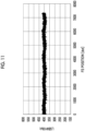
- Fig. 11 is a graph illustrating an output value of light reflected by the mirror surface reflecting plate 220 in a case where the diffusion plate 230 is disposed at the mirror surface reflecting plate 220. In this graph, it can be seen that an output value of light reflected by the mirror surface reflecting plate 220 reaches a target value of approximately 400 LSB.
- a surface with low reflection that is, a surface with low specular reflectance is disposed on the image reading unit 100 side.
- the light diffusion layer 234 is disposed on the image reading unit 100 side of the base material 232
- the backing coat layer 236 is disposed on the mirror surface reflecting plate 220 side of the base material 232.
- Fig. 14 is a graph illustrating an output value of light reflected by the mirror surface reflecting plate 220 in a case where the light diffusion layer 234 is disposed on the image reading unit 100 side.
- Fig. 15 is a partially enlarged graph of the graph in Fig. 14 . In these graphs, it can be seen that in a case where the light diffusion layer 234 is provided on the image reading unit 100 side, almost no unevenness remains.
- a surface of the backing coat layer 236 is used as a surface with high reflection
- a surface of the light diffusion layer 234 is used as a surface with low reflection
- the light diffusion layer 234 is disposed to face the light receiving unit 125 side.
- the surface to be used is not limited to this. More generalized, a surface of a first layer having a first specular reflectance may be used as a surface with high reflection and a surface of a second layer having a second specular reflectance lower than the first specular reflectance may be used as a surface with low reflection, and the second layer may be disposed to face the light receiving unit side.
- the backing coat layer 236 is an example of the first layer
- the light diffusion layer 234 is an example of the second layer.
- recess portions are provided along a longitudinal direction of the light guide body 110 on the image reading unit 100 side of the mirror surface reflecting plate 220. That is, in the modification example of the mirror surface reflecting plate 220, the recess portions blur an apparent distance away, thereby eliminating the occurrence of unevenness.
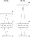
- Figs. 16A and 16B are diagrams illustrating the modification example of the mirror surface reflecting plate 220 in the present exemplary embodiment.
- Fig 16A is a diagram in a case where a recess portion is not provided on the image reading unit 100 side of the mirror surface reflecting plate 220. In this case, a focus point is focused on the light receiving unit 125, and unevenness occurs.
- Fig. 16B is a diagram in a case where recess portions are provided on the image reading unit 100 side of the mirror surface reflecting plate 220. In this case, a distance from the mirror surface reflecting plate 220 to the rod lens array 112 becomes long, light on the light receiving unit 125 spreads, and unevenness becomes small.
- the recess portions are provided along the longitudinal direction of the light guide body 110 on the image reading unit 100 side of the mirror surface reflecting plate 220, and the description is not limited to this.
- the mirror surface reflecting plate 220 may have a property of preventing the light receiving unit 125 from being located within a focal depth of the rod lens array 112.
- a method of disposing a recessed shape in a direction in which a side surface of the light guide body 110 extends is used as an example of a method in which the mirror surface reflecting plate 220 has such a property.
- the sheet-shaped diffusion plate 230 may be attached along the recess portions of the mirror surface reflecting plate 220.
- the reading guide member 210 to which the mirror surface reflecting plate 220 is attached may be provided with a recess portion, and the sheet-shaped mirror surface reflecting plate 220 and diffusion plate 230 may be attached along the recess portions of the reading guide member 210.
Landscapes
- Physics & Mathematics (AREA)
- General Physics & Mathematics (AREA)
- Optics & Photonics (AREA)
- Engineering & Computer Science (AREA)
- Multimedia (AREA)
- Signal Processing (AREA)
- Microelectronics & Electronic Packaging (AREA)
- Theoretical Computer Science (AREA)
- Facsimile Scanning Arrangements (AREA)
- Facsimile Heads (AREA)
Abstract
Description
- The present invention relates to an optical device and a document reading apparatus.
- In
JP2015-019213A - In
JP2015-012347A - In
JP2015-023428A - In a case where the light guide body scatters the light incident from an end surface with a scatterer disposed in a direction in which a side surface extends, the amount of light received by the light receiving unit is reduced, and in a case where the amount of light is increased, the uneven amounts of light received by the light receiving unit occur.
- An object of the present invention is to reduce, in a case where a light guide body scatters light incident from an end surface with a scatterer disposed in a direction in which a side surface extends and emits the light, both a decrease in the amount of light received by a light receiving unit and occurrence of the uneven amounts of light received by the light receiving unit.
- According to a first aspect of the present disclosure, there is provided an optical device including: a light guide body that scatters light incident from an end surface with a scatterer disposed in a direction in which a side surface extends and emits the light; a mirror surface reflecting plate that mirror-reflects the light emitted from the light guide body; a light receiving unit that receives the light reflected by the mirror surface reflecting plate; and a diffusion plate that diffuses and transmits the light emitted from the light guide body and emits the light onto the mirror surface reflecting plate, and diffuses and transmits the light reflected by the mirror surface reflecting plate and emits the light to the light receiving unit.
- According to a second aspect of the present invention, in the optical device according to the first aspect, the diffusion plate may include a first layer having a first specular reflectance and a second layer having a second specular reflectance lower than the first specular reflectance, and the second layer is disposed to face a light receiving unit side.
- According to a third aspect of the present invention, in the optical device according to the second aspect, in which the first layer may be a backing coat layer, and the second layer is a light diffusion layer.
- According to a fourth aspect of the present invention, the optical device according to the first aspect, further includes: a lens unit that guides the light reflected by the mirror surface reflecting plate to the light receiving unit, in which the mirror surface reflecting plate may have a property of preventing the light receiving unit from being located within a focal depth of the lens unit.
- According to a fifth aspect of the present invention, in the optical device according to the fourth aspect, in which the mirror surface reflecting plate may be provided with a recess portion shape disposed in a direction in which the side surface of the light guide body extends, to have the property.
- According to a sixth aspect of the present disclosure, there is provided a document reading apparatus including: a light source that is provided on an end surface side of a light guide body and emits light; a reading window portion through which a document passes; and the optical device according to any one of the first aspect to the fifth aspect, in which in a case where the document passes through the reading window portion, the light receiving unit receives the light emitted from the light guide body and reflected by the document, and in a case where the document does not pass through the reading window portion, the light receiving unit receives the light reflected by the mirror surface reflecting plate.
- With the first aspect of the present invention, in a case where the light guide body scatters the light incident from the end surface with the scatterer disposed in the direction in which the side surface extends and emits the light, it is possible to reduce both a decrease in the amount of light received by the light receiving unit and occurrence of the uneven amounts of light received by the light receiving unit.
- With the second aspect of the present invention, it is possible to further decrease a possibility that the amount of light received by the light receiving unit is reduced.
- With the third aspect of the present invention, it is possible to easily decrease the possibility that the amount of light received by the light receiving unit is reduced.
- With the fourth aspect of the present invention, it is possible to further decrease the possibility of the occurrence of the uneven amounts of light received by the light receiving unit.
- With the fifth aspect of the present invention, it is possible to easily decrease the possibility of the occurrence of the uneven amounts of light received by the light receiving unit.
- With the sixth aspect of the present invention, in a case where the light guide body scatters the light incident from the end surface with the scatterer disposed in the direction in which the side surface extends and emits the light, it is possible to reduce both a decrease in the amount of light received by the light receiving unit and occurrence of the uneven amounts of light received by the light receiving unit.
- Exemplary embodiment(s) of the present invention will be described in detail based on the following figures, wherein:
-
Fig. 1 is a diagram illustrating a configuration example of an image reading apparatus according to the present exemplary embodiment; -
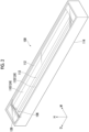
Fig. 2 is a perspective view illustrating an image reading unit according to the present exemplary embodiment; -
Fig. 3 is an exploded perspective view illustrating the image reading unit according to the present exemplary embodiment; -
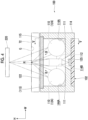
Fig. 4 is a cross-sectional diagram (cross-sectional diagram taken along a line IV-IV ofFig. 5 ) illustrating the image reading unit according to the present exemplary embodiment; -
Fig. 5 is a cross-sectional diagram (cross-sectional diagram taken along a line V-V ofFig. 4 ) illustrating the image reading unit according to the present exemplary embodiment; -
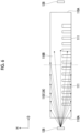
Fig. 6 is an explanatory diagram describing a diffusion pattern and light emitted from a light emitting element according to the present exemplary embodiment; -
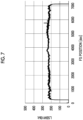
Fig. 7 is a first graph illustrating an output value of light reflected by a mirror surface reflecting plate; -
Fig. 8 is a second graph illustrating the output value of the light reflected by the mirror surface reflecting plate; -
Fig. 9 is a diagram illustrating a dust detection and correction function; -
Fig. 10 is a diagram illustrating a configuration example of the mirror surface reflecting plate according to the present exemplary embodiment; -
Fig. 11 is a graph illustrating an output value of light reflected by the mirror surface reflecting plate in a case where a diffusion plate is disposed at the mirror surface reflecting plate; -
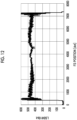
Fig. 12 is a graph illustrating an output value of light reflected by the mirror surface reflecting plate in a case where a backing coat layer is disposed on an image reading unit side; -
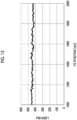
Fig. 13 is a partially enlarged graph of the graph inFig. 12 ; -
Fig. 14 is a graph illustrating an output value of light reflected by the mirror surface reflecting plate in a case where a light diffusion layer is disposed on the image reading unit side; -
Fig. 15 is a partially enlarged graph of the graph inFig. 14 ; and -
Figs. 16A and 16B are diagrams illustrating a modification example of the mirror surface reflecting plate according to the present exemplary embodiment. - Hereinafter, exemplary embodiments of the present invention will be described in detail with reference to the accompanying drawings.
-
Fig. 1 is a diagram illustrating a configuration example of animage reading apparatus 60 according to the present exemplary embodiment. InFig. 1 , an up-down direction is indicated by H, and an apparatus width direction is indicated by W, respectively. - As illustrated in
Fig. 1 , theimage reading apparatus 60 includes a first transparent plate 62 (so-called platen glass) on which a document G is placed in a case where an image of one document G is read, and a secondtransparent plate 72 disposed on one side (left side inFig. 1 ) of the firsttransparent plate 62 in the apparatus width direction. The firsttransparent plate 62 and the secondtransparent plate 72 are fitted in an upper portion of a housing 60A in theimage reading apparatus 60. - Above the first
transparent plate 62 and the secondtransparent plate 72, an opening andclosing cover 66 which opens or closes the firsttransparent plate 62 and the secondtransparent plate 72 is disposed. Inside the opening andclosing cover 66, a transport unit 64 (so-called an ADF) which transports a plurality of documents G along atransport path 70 in the opening and closingcover 66 and passes the plurality of documents G through a document reading position R above the secondtransparent plate 72 is provided. Further, thetransport unit 64 includes areading guide member 210 that guides the document G being transported along thetransport path 70 to the document reading position R and guides the document G in a discharge direction after passing through the document reading position R. Further, thereading guide member 210 is provided with a mirrorsurface reflecting plate 220 at a part of a lower surface portion facing the document reading position R. - In addition, in a space inside the housing 60A, an
image reading unit 100 which reads an image of the document G placed on the firsttransparent plate 62 and the image of the document G transported to the document reading position R by thetransport unit 64 is provided. Further, theimage reading apparatus 60 includes adrive unit 74 which drives theimage reading unit 100 in the apparatus width direction. - The
drive unit 74 includes ashaft 76 extending in the apparatus width direction (a moving direction of the image reading unit 100) and asliding member 78 which is attached to a lower surface of ahousing 114 of theimage reading unit 100 and which is slidably supported by theshaft 76. - Further, the
drive unit 74 includes a motor (not illustrated), adrive pulley 84 which is rotationally driven by transmission of a drive force from the motor, a drivenpulley 86 which is driven and rotated, and anendless belt 82 in an endless shape winding around thedrive pulley 84 and the drivenpulley 86. Thedrive pulley 84 is attached to one end of theshaft 76, and the drivenpulley 86 is attached to the other end of theshaft 76. - Details of the
image reading unit 100 will be described below. - In the
image reading apparatus 60, theimage reading unit 100 reads the image of the document G as follows. Specifically, in a case of reading the image of the document G transported by thetransport unit 64, a drive force of the motor (not illustrated) is transmitted via theendless belt 82, so that theimage reading unit 100 moves to a transport reading position on the other side in the apparatus width direction and stops, as illustrated inFig. 1 . Theimage reading unit 100 disposed at the transport reading position reads the image of the document G transported by thetransport unit 64. - Further, in a case of reading the image of the document G placed on the first
transparent plate 62, although not illustrated, theimage reading unit 100 moves from a reading start position toward a reading end position in the apparatus width direction along the firsttransparent plate 62 by thedrive unit 74, while reading the image of the document G. - Here, the
image reading apparatus 60 is an example of a document reading apparatus. -
Fig. 2 is a perspective view illustrating theimage reading unit 100 according to the present exemplary embodiment. -
Fig. 3 is an exploded perspective view illustrating theimage reading unit 100 according to the present exemplary embodiment. -
Fig. 4 is a cross-sectional diagram illustrating theimage reading unit 100 according to the present exemplary embodiment. Specifically,Fig. 4 is a cross-sectional diagram taken along a line IV-IV ofFig. 5 .Fig. 4 also illustrates the secondtransparent plate 72 and the mirrorsurface reflecting plate 220, which are not strictly components of theimage reading unit 100. -
Fig. 5 is a cross-sectional diagram illustrating theimage reading unit 100 according to the present exemplary embodiment. Specifically,Fig. 5 is a cross-sectional diagram taken along a line V-V ofFig. 4 . -
Fig. 6 is an explanatory diagram describing a diffusion pattern and light emitted from a light emitting element according to the present exemplary embodiment. - In these drawings, an up-down direction is indicated by H, an apparatus width direction is indicated by W, and an apparatus depth direction is indicated by D, respectively.
- As illustrated in
Figs. 2 to 6 , theimage reading unit 100 includes alight emitting unit 124 that irradiates the document G with light, alight receiving unit 125 that receives light, arod lens array 112 that guides light to thelight receiving unit 125, and aglass plate 122. Theimage reading unit 100 reads an image formed on the document G by using a known contact image sensor (CIS) method. - Further, in a case where the
image reading unit 100 reads the image of the document G transported by thetransport unit 64, theimage reading unit 100 is disposed in a downward direction of the secondtransparent plate 72 and is directly below the mirrorsurface reflecting plate 220, as illustrated inFig. 4 . In this case, the document G transported by thetransport unit 64 passes through the document reading position R on the secondtransparent plate 72. Then, in a case where the document G passes the document reading position R on the secondtransparent plate 72, the document G reflects light emitted from aside surface 110B of alight guide body 110 to be described below. On the other hand, in a case where the document G does not pass through the document reading position R on the secondtransparent plate 72, the mirrorsurface reflecting plate 220 reflects the light emitted from theside surface 110B of thelight guide body 110 to be described below. - Here, the second
transparent plate 72 is an example of a reading window portion through which a document passes. Further, the mirrorsurface reflecting plate 220 is an example of a mirror surface reflecting plate that mirror-reflects light emitted from a light guide body. - The
light receiving unit 125 has alight receiving substrate 102 and a plurality of light receivingelements 126 arranged in the apparatus depth direction. As illustrated inFig. 3 , a plate thickness direction of thelight receiving substrate 102 is an up-down direction. Thelight receiving substrate 102 has a rectangular shape extending in the apparatus depth direction, as viewed from above, and is disposed below thehousing 114. Further, the plurality of light receivingelements 126 are mounted at an upper surface of thelight receiving substrate 102. - In a case where the document G passes through the document reading position R on the second
transparent plate 72, thelight receiving unit 125 receives light emitted from theside surface 110B of thelight guide body 110, which will be described below, and reflected by the document G. On the other hand, in a case where the document G does not pass through the document reading position R on the secondtransparent plate 72, thelight receiving unit 125 receives light emitted from theside surface 110B of thelight guide body 110, which will be described below, and reflected by the mirrorsurface reflecting plate 220. - Here, the
light receiving unit 125 is an example of a light receiving unit that receives light reflected by a mirror surface reflecting plate. In addition, thelight receiving unit 125 is an example of a light receiving unit that receives light emitted from a light guide body and reflected by a document in a case where the document passes through a reading window portion, and receives light reflected by a mirror surface reflecting plate in a case where the document does not pass through the reading window portion. - The
rod lens array 112 is made of a transparent material (for example, glass), is formed in a rectangular parallelepiped shape extending in the apparatus depth direction, and is accommodated in alens accommodating portion 114B in thehousing 114, as illustrated inFig. 4 . In a case where the document G passes through the document reading position R on the secondtransparent plate 72, therod lens array 112 is configured such that light is emitted from theside surface 110B of thelight guide body 110, which will be described below, and is reflected by the document G, and is collected by thelight receiving element 126. On the other hand, in a case where the document G does not pass through the document reading position R on the secondtransparent plate 72, therod lens array 112 is configured such that light is emitted from theside surface 110B of thelight guide body 110, which will be described below, is reflected by the mirrorsurface reflecting plate 220, and is collected by thelight receiving element 126. - Here, the
rod lens array 112 is an example of a lens unit that guides light reflected by a mirror surface reflecting plate to a light receiving unit. - As illustrated in
Fig. 3 , a plate thickness direction of theglass plate 122 is an up-down direction, and theglass plate 122 has a rectangular shape extending in the apparatus depth direction, as viewed from above. As illustrated inFig. 4 , theglass plate 122 is fixed to thehousing 114 by a fixing section (not illustrated) in a state in which an edge portion of theglass plate 122 is in contact with astep portion 115 of thehousing 114, and is disposed to cover an upper surface of thehousing 114. - As illustrated in
Figs. 3 and4 , thelight emitting unit 124 includes thelight guide body 110, anirradiation unit 103, and thehousing 114 constituting the apparatus main body. Thelight emitting unit 124 has twolight guide bodies 110, and the respectivelight guide bodies 110 are arranged in parallel to be symmetrical with respect to a center of thehousing 114 in the apparatus width direction. - As illustrated in
Fig. 3 , thelight guide body 110 is formed in a cylindrical shape using a transparent material (for example, acrylic resin), and extends in the apparatus depth direction as a longitudinal direction. Thelight guide body 110 is accommodated in a light guidebody accommodating portion 114A of thehousing 114. Further, thelight guide body 110 advances light incident on oneend surface 110A in the longitudinal direction, and irradiates the document G with light emitted from theside surface 110B. - Further, as illustrated in
Figs. 4 to 6 , thelight guide body 110 is provided with adiffusion pattern 111 that diffuses light incident from theend surface 110A of thelight guide body 110 and advances the light in the longitudinal direction, and emits the light toward an upper side of the rod lens array 112 (in an arrow B direction inFig. 4 ). Further, as illustrated inFig. 4 , thediffusion pattern 111 is disposed on an opposite side not facing the document G, of theside surface 110B of thelight guide body 110. More specifically, thediffusion pattern 111 is disposed on the opposite side not facing the document G of the side surfaces 110B of the twolight guide bodies 110, and on a side away from the otherlight guide body 110. That is, thediffusion pattern 111 is displaced at a position at which a center of the fan-shapeddiffusion pattern 111 illustrated inFig. 4 in the apparatus width direction passes through a center of thelight guide body 110 and faces the document reading position R, not directly below thelight guide body 110 in an apparatus downward direction. Further, as illustrated inFig. 6 , thediffusion patterns 111 are provided over thelight guide body 110 in the longitudinal direction at predetermined intervals. Here, as an example, thediffusion pattern 111 is configured with solidified white paint, and diffuses light traveling inside thelight guide body 110 and advances the light toward an upper surface side (document G side) of thelight guide body 110. Alternatively, a prism may be used as thediffusion pattern 111. - Here, the
diffusion pattern 111 is an example of a scatterer disposed in a direction in which a side surface extends. Further, thelight guide body 110 is an example of a light guide body that emits light incident from an end surface after being scattered by the scatterer. - As illustrated in
Fig. 3 , theirradiation unit 103 includes awiring substrate 104, anelement substrate 106, and an LED light emitting element 128 (hereinafter, "light emittingelement 128"). - The
wiring substrate 104 is a so-called flexible flat cable, and is provided in pairs, as illustrated inFig. 3 . A base end of onewiring substrate 104 is connected to an end portion of thelight receiving substrate 102 on the back side (left side inFig. 3 ) in the apparatus depth direction, and a base end of theother wiring substrate 104 is connected to an end portion of thelight receiving substrate 102 on the front side (right side inFig. 3 ) in the apparatus depth direction. - The
element substrate 106 is a so-called flexible printed circuit substrate, and a plate thickness direction of theelement substrate 106 is the apparatus depth direction. Theelement substrate 106 is a substrate having a rectangular shape as viewed from the apparatus depth direction, is accommodated in asubstrate accommodating portion 114C of thehousing 114, and is provided in pairs, as illustrated inFig 3 . Oneelement substrate 106 is connected to a tip of onewiring substrate 104, and theother element substrate 106 is connected to a tip of theother wiring substrate 104. Further, thelight emitting elements 128 arranged in the apparatus width direction are mounted on one surface of eachelement substrate 106. Thelight emitting element 128 is an example of a light source that is provided on an end surface side of a light guide body, and emits light. Here, theelement substrate 106 may have flexibility. The flexibility means, for example, that a substrate having a width of 10 mm is supported in a cantilevered state, and a portion of 10 mm from a support end is pushed from above with a force of 9.8 N and the amount of deflection becomes 1 mm or more. - As illustrated in
Fig. 5 , thelight emitting element 128 is disposed on a surface of theelement substrate 106 on thelight guide body 110 side for each of the twolight guide bodies 110 to face theend surface 110A of thelight guide body 110. Each of thelight emitting elements 128 emits light to irradiate theend surface 110A with the light. - Meanwhile, in such an
image reading apparatus 60, in a case where thetransport unit 64 transports the document G along thetransport path 70, the document G is tilted in some cases. In preparation for such a case, theimage reading apparatus 60 may have a function of mechanically correcting the inclination of the document G (hereinafter, "mechanical skew correction function"). With the mechanical skew correction function, an inclination of a tip of the document G is corrected by abutting the document G against a stopped roller to create a loop, and a variation in a timing at which each location of the tip of the document G arrives at the document reading position R is reduced. Meanwhile, this mechanical skew correction function has a problem in that an impact sound in a case where the tip of the document G collides with the roller, an impact sound in a case where the loop of the document G is created or eliminated, and the like are generated. - In order to address such a problem, the
image reading apparatus 60 may have a function of detecting a tilt angle of the document G and correcting the tilt angle by image processing. Meanwhile, the tilt angle of the document G cannot detected in a case where a difference between an output value of light reflected by the document G in a case where the document G passes through the document reading position R, and an output value of light reflected by the mirrorsurface reflecting plate 220 in a case where the document G does not pass through the document reading position R is equal to or more than a predetermined reference. Specifically, for example, in a case of 8-bit 256 gradations output, an output value of light reflected by the document G of a color of white is a value close to 240 LSB, so that an output value of light reflected by the mirrorsurface reflecting plate 220 is to be higher than 240 LSB. - Meanwhile, in a case where the
light emitting element 128 adopts an illumination system that emits light from theend surface 110A of thelight guide body 110 as in theimage reading apparatus 60 described above, an output of the light from thelight guide body 110 is reduced, so that an output of light reflected by the mirrorsurface reflecting plate 220 is also reduced. Further, in order to increase a speed of image reading or increase a focal depth, it is required to increase the output of the reflected light. Meanwhile, theimage reading apparatus 60 described above cannot meet such a requirement. - Although a last output is illustrated in a form of 256 gradations output in the previous example, in a stage before the last output, a process is performed with a larger number of gradations, for example, 10-bit 1024 gradations, and the last output is rounded with 8-bit 256 gradations, in some cases. In the following, for the sake of description, a 10-bit output will be used.
-
Fig. 7 is a first graph illustrating an output value of light reflected by the mirrorsurface reflecting plate 220. Here, the output value of the reflected light is measured by using the mirrorsurface reflecting plate 220 of the existing technique. In order to detect a tilt angle of the document G, the output value of the reflected light by the mirrorsurface reflecting plate 220 needs to be approximately 400 LSB. Meanwhile, in the first graph, the output value of the reflected light does not reach approximately 400 LSB, and it can be seen that the output of the reflected light is insufficient. -
Fig. 8 is a second graph illustrating an output value of light reflected by the mirrorsurface reflecting plate 220. Here, the output value of the reflected light is measured by using the mirrorsurface reflecting plate 220 of the existing technique having a high reflectance. In the second graph, it can be seen that the output value of the light reflected by the mirrorsurface reflecting plate 220 reaches approximately 400 LSB, meanwhile, the uneven amounts of light (hereinafter, also simply referred to as "unevenness") occur due to projection of the diffusion pattern 111 (regions M1 and M2). - That is, there is no mirror
surface reflecting plate 220 of the existing technique that does not cause a shortage of output of the reflected light and does not cause occurrence of the unevenness. - In addition, in recent years, the
image reading apparatus 60 may have a function of detecting and correcting dust on the second transparent plate 72 (hereinafter, referred to as a "dust detection and correction function"). -
Fig. 9 is a diagram describing the dust detection and correction function. In a case where there is dust on the secondtransparent plate 72, an image of the document G is such that streaks S appear in a transport direction at the same locations in the width direction as illustrated. In this case, with the dust detection and correction function, it is determined that such streaks S are caused by the dust on the secondtransparent plate 72, and the streaks S are removed by image processing. - On the other hand, in a case where a lower limit of a region (regions M1 and M2 in
Fig. 8 ) in which the reflectance of the mirrorsurface reflecting plate 220 is increased and unevenness occurs exceeds a target value, the inclination of the document G can be detected, but the unevenness cannot be distinguished from the streaks S illustrated inFig. 9 and the dust cannot be detected by the dust detection and correction function. -
Fig. 10 is a diagram illustrating a configuration example of the mirrorsurface reflecting plate 220 according to the present exemplary embodiment. As illustrated inFig. 10 , adiffusion plate 230 is disposed on theimage reading unit 100 side at a lower surface of the mirrorsurface reflecting plate 220 in the present exemplary embodiment. Further, in thediffusion plate 230, alight diffusion layer 234 is provided on theimage reading unit 100 side of abase material 232, and abacking coat layer 236 is provided on the mirrorsurface reflecting plate 220 side of thebase material 232. - In a case where the mirror
surface reflecting plate 220 and thediffusion plate 230 are combined in this manner, light emitted from thelight guide body 110 passes through thediffusion plate 230, and the light reflected by the mirrorsurface reflecting plate 220 passes through thediffusion plate 230 again. That is, the light passes through thediffusion plate 230 twice. Thus, it is possible to increase the output of the light reflected by the mirrorsurface reflecting plate 220, and reduce the unevenness due to the reflected light. - Here, the
diffusion plate 230 is an example of a diffusion plate that diffuses and transmits light emitted from a light guide body and emits the light on a mirror surface reflecting plate, and diffuses and transmits the light reflected by the mirror surface reflecting plate and emits the light to a light receiving unit. Further, a portion including thelight guide body 110, the mirrorsurface reflecting plate 220, thediffusion plate 230, and thelight receiving unit 125 is an example of an optical device. -
Fig. 11 is a graph illustrating an output value of light reflected by the mirrorsurface reflecting plate 220 in a case where thediffusion plate 230 is disposed at the mirrorsurface reflecting plate 220. In this graph, it can be seen that an output value of light reflected by the mirrorsurface reflecting plate 220 reaches a target value of approximately 400 LSB. - Meanwhile, in
Fig. 10 , it is conceivable to dispose the light diffusion layers 234 on both sides of thebase material 232, but in that case, the output of the light reflected by the mirrorsurface reflecting plate 220 is insufficient. - Further, in
Fig. 10 , it is conceivable to dispose thebacking coat layer 236 on theimage reading unit 100 side of thebase material 232 and to dispose thelight diffusion layer 234 on the mirrorsurface reflecting plate 220 side of thebase material 232, but in this case as well, the output of the light reflected by the mirrorsurface reflecting plate 220 is insufficient. - Therefore, in the present exemplary embodiment, among the surfaces of the
diffusion plate 230, a surface with low reflection, that is, a surface with low specular reflectance is disposed on theimage reading unit 100 side. Specifically, thelight diffusion layer 234 is disposed on theimage reading unit 100 side of thebase material 232, and thebacking coat layer 236 is disposed on the mirrorsurface reflecting plate 220 side of thebase material 232. -
Fig. 12 is a graph illustrating an output value of light reflected by the mirrorsurface reflecting plate 220 in a case where thebacking coat layer 236 is disposed on theimage reading unit 100 side.Fig. 13 is a partially enlarged graph of the graph inFig. 12 . In these graphs, it can be seen that some unevenness remains in a case where thebacking coat layer 236 is provided on theimage reading unit 100 side. -
Fig. 14 is a graph illustrating an output value of light reflected by the mirrorsurface reflecting plate 220 in a case where thelight diffusion layer 234 is disposed on theimage reading unit 100 side.Fig. 15 is a partially enlarged graph of the graph inFig. 14 . In these graphs, it can be seen that in a case where thelight diffusion layer 234 is provided on theimage reading unit 100 side, almost no unevenness remains. - In the above description, a surface of the
backing coat layer 236 is used as a surface with high reflection, a surface of thelight diffusion layer 234 is used as a surface with low reflection, and thelight diffusion layer 234 is disposed to face thelight receiving unit 125 side. Meanwhile, the surface to be used is not limited to this. More generalized, a surface of a first layer having a first specular reflectance may be used as a surface with high reflection and a surface of a second layer having a second specular reflectance lower than the first specular reflectance may be used as a surface with low reflection, and the second layer may be disposed to face the light receiving unit side. In this case, thebacking coat layer 236 is an example of the first layer, and thelight diffusion layer 234 is an example of the second layer. - In a modification example of the mirror
surface reflecting plate 220 according to the present exemplary embodiment, recess portions are provided along a longitudinal direction of thelight guide body 110 on theimage reading unit 100 side of the mirrorsurface reflecting plate 220. That is, in the modification example of the mirrorsurface reflecting plate 220, the recess portions blur an apparent distance away, thereby eliminating the occurrence of unevenness. -
Figs. 16A and 16B are diagrams illustrating the modification example of the mirrorsurface reflecting plate 220 in the present exemplary embodiment. -
Fig 16A is a diagram in a case where a recess portion is not provided on theimage reading unit 100 side of the mirrorsurface reflecting plate 220. In this case, a focus point is focused on thelight receiving unit 125, and unevenness occurs. -
Fig. 16B is a diagram in a case where recess portions are provided on theimage reading unit 100 side of the mirrorsurface reflecting plate 220. In this case, a distance from the mirrorsurface reflecting plate 220 to therod lens array 112 becomes long, light on thelight receiving unit 125 spreads, and unevenness becomes small. - In addition, in
Figs. 16A and 16B , the mirrorsurface reflecting plate 220 is disposed at the same position in the up-down direction. Meanwhile, here, in order to emphasize that the distance from the mirrorsurface reflecting plate 220 to therod lens array 112 is longer inFig. 16B than inFig. 16A , the mirrorsurface reflecting plate 220 inFig. 16B is illustrated to be disposed at a higher position in the up-down direction than the mirrorsurface reflecting plate 220 inFig. 16A . - In the above description, the recess portions are provided along the longitudinal direction of the
light guide body 110 on theimage reading unit 100 side of the mirrorsurface reflecting plate 220, and the description is not limited to this. The mirrorsurface reflecting plate 220 may have a property of preventing thelight receiving unit 125 from being located within a focal depth of therod lens array 112. In the above description, as an example of a method in which the mirrorsurface reflecting plate 220 has such a property, a method of disposing a recessed shape in a direction in which a side surface of thelight guide body 110 extends is used. - In the modification example of the mirror
surface reflecting plate 220, for example, the sheet-shapeddiffusion plate 230 may be attached along the recess portions of the mirrorsurface reflecting plate 220. - Further, even in a case where the mirror
surface reflecting plate 220 is not provided with the recess portion, for example, the readingguide member 210 to which the mirrorsurface reflecting plate 220 is attached may be provided with a recess portion, and the sheet-shaped mirrorsurface reflecting plate 220 anddiffusion plate 230 may be attached along the recess portions of the readingguide member 210. -
- (((1))) An optical device comprising:
- a light guide body that scatters light incident from an end surface with a scatterer disposed in a direction in which a side surface extends and emits the light;
- a mirror surface reflecting plate that mirror-reflects the light emitted from the light guide body;
- a light receiving unit that receives the light reflected by the mirror surface reflecting plate; and
- a diffusion plate that diffuses and transmits the light emitted from the light guide body and emits the light onto the mirror surface reflecting plate, and diffuses and transmits the light reflected by the mirror surface reflecting plate and emits the light to the light receiving unit.
- (((2))) The optical device according to (((1))), wherein the diffusion plate includes a first layer having a first specular reflectance and a second layer having a second specular reflectance lower than the first specular reflectance, and the second layer is disposed to face a light receiving unit side.
- (((3))) The optical device according to (((2))),
- wherein the first layer is a backing coat layer, and
- the second layer is a light diffusion layer.
- (((4))) The optical device according to (((1))), further comprising:
- a lens unit that guides the light reflected by the mirror surface reflecting plate to the light receiving unit,
- wherein the mirror surface reflecting plate has a property of preventing the light receiving unit from being located within a focal depth of the lens unit.
- (((5))) The optical device according to ((4))),
wherein the mirror surface reflecting plate is provided with a recess portion shape disposed in a direction in which the side surface of the light guide body extends, to have the property. - (((6))) A document reading apparatus comprising:
- a light source that is provided on an end surface side of a light guide body and emits light;
- a reading window portion through which a document passes; and
- the optical device according to any one of (((1))) to (((5))),
- wherein in a case where the document passes through the reading window portion, the light receiving unit receives the light emitted from the light guide body and reflected by the document, and in a case where the document does not pass through the reading window portion, the light receiving unit receives the light reflected by the mirror surface reflecting plate.
- With an exemplary embodiment of the invention (((1))), in a case where the light guide body scatters the light incident from the end surface with the scatterer disposed in the direction in which the side surface extends and emits the light, it is possible to reduce both a decrease in the amount of light received by the light receiving unit and occurrence of the uneven amounts of light received by the light receiving unit.
- With the exemplary embodiment of the invention (((2))), it is possible to further decrease a possibility that the amount of light received by the light receiving unit is reduced.
- With the exemplary embodiment of the invention (((3))), it is possible to easily decrease the possibility that the amount of light received by the light receiving unit is reduced.
- With the exemplary embodiment of the invention (((4))), it is possible to further decrease the possibility of the occurrence of the uneven amounts of light received by the light receiving unit.
- With the exemplary embodiment of the invention (((5))), it is possible to easily decrease the possibility of the occurrence of the uneven amounts of light received by the light receiving unit.
- With another exemplary embodiment of the invention (((6))), in a case where the light guide body scatters the light incident from the end surface with the scatterer disposed in the direction in which the side surface extends and emits the light, it is possible to reduce both a decrease in the amount of light received by the light receiving unit and occurrence of the uneven amounts of light received by the light receiving unit.
- The foregoing description of the exemplary embodiments of the present invention has been provided for the purposes of illustration and description. It is not intended to be exhaustive or to limit the invention to the precise forms disclosed. Obviously, many modifications and variations will be apparent to practitioners skilled in the art. The embodiments were chosen and described in order to best explain the principles of the invention and its practical applications, thereby enabling others skilled in the art to understand the invention for various embodiments and with the various modifications as are suited to the particular use contemplated. It is intended that the scope of the invention be defined by the following claims and their equivalents.
-
- 60: image reading apparatus
- 100: image reading unit
- 110: light guide body
- 110A: end surface
- 110B: side surface
- 111: diffusion pattern
- 112: rod lens array
- 125: light receiving unit
- 128: light emitting element
- 220: mirror surface reflecting plate
- 230: diffusion plate
- 232: base material
- 234: light diffusion layer
- 236: backing coat layer
Claims (6)
- An optical device comprising:a light guide body that scatters light incident from an end surface with a scatterer disposed in a direction in which a side surface extends and emits the light;a mirror surface reflecting plate that mirror-reflects the light emitted from the light guide body;a light receiving unit that receives the light reflected by the mirror surface reflecting plate; anda diffusion plate that diffuses and transmits the light emitted from the light guide body and emits the light onto the mirror surface reflecting plate, and diffuses and transmits the light reflected by the mirror surface reflecting plate and emits the light to the light receiving unit.
- The optical device according to claim 1,
wherein the diffusion plate includes a first layer having a first specular reflectance and a second layer having a second specular reflectance lower than the first specular reflectance, and the second layer is disposed to face a light receiving unit side. - The optical device according to claim 2,wherein the first layer is a backing coat layer, andthe second layer is a light diffusion layer.
- The optical device according to claim 1, further comprising:a lens unit that guides the light reflected by the mirror surface reflecting plate to the light receiving unit,wherein the mirror surface reflecting plate has a property of preventing the light receiving unit from being located within a focal depth of the lens unit.
- The optical device according to claim 4,
wherein the mirror surface reflecting plate is provided with a recess portion shape disposed in a direction in which the side surface of the light guide body extends, to have the property. - A document reading apparatus comprising:a light source that is provided on an end surface side of a light guide body and emits light;a reading window portion through which a document passes; andthe optical device according to any one of claims 1 to 5,wherein in a case where the document passes through the reading window portion, the light receiving unit receives the light emitted from the light guide body and reflected by the document, and in a case where the document does not pass through the reading window portion, the light receiving unit receives the light reflected by the mirror surface reflecting plate.
Applications Claiming Priority (1)
| Application Number | Priority Date | Filing Date | Title |
|---|---|---|---|
| JP2023123033A JP2025019425A (en) | 2023-07-28 | 2023-07-28 | Optical device and document reading device |
Publications (2)
| Publication Number | Publication Date |
|---|---|
| EP4498668A1 true EP4498668A1 (en) | 2025-01-29 |
| EP4498668B1 EP4498668B1 (en) | 2025-12-31 |
Family
ID=89854355
Family Applications (1)
| Application Number | Title | Priority Date | Filing Date |
|---|---|---|---|
| EP24156337.8A Active EP4498668B1 (en) | 2023-07-28 | 2024-02-07 | OPTICAL DEVICE AND DOCUMENT READER |
Country Status (4)
| Country | Link |
|---|---|
| US (1) | US20250035835A1 (en) |
| EP (1) | EP4498668B1 (en) |
| JP (1) | JP2025019425A (en) |
| CN (1) | CN119439599A (en) |
Citations (6)
| Publication number | Priority date | Publication date | Assignee | Title |
|---|---|---|---|---|
| US20090073510A1 (en) * | 2006-02-16 | 2009-03-19 | Kurt Eugene Spears | Passive Transparent Media Adapter |
| US7714270B2 (en) * | 2008-03-20 | 2010-05-11 | Xerox Corporation | Convex lenslet array diffuser |
| JP2015012347A (en) | 2013-06-27 | 2015-01-19 | 富士ゼロックス株式会社 | Document reading device and image forming apparatus |
| JP2015019213A (en) | 2013-07-10 | 2015-01-29 | 富士ゼロックス株式会社 | Document reading apparatus and image forming apparatus |
| JP2015023428A (en) | 2013-07-19 | 2015-02-02 | 富士ゼロックス株式会社 | Document reading device and image forming apparatus |
| US20230133357A1 (en) * | 2021-10-29 | 2023-05-04 | Fujifilm Business Innovation Corp. | Reading apparatus, image forming apparatus, and reading method |
-
2023
- 2023-07-28 JP JP2023123033A patent/JP2025019425A/en active Pending
-
2024
- 2024-02-07 US US18/434,859 patent/US20250035835A1/en active Pending
- 2024-02-07 EP EP24156337.8A patent/EP4498668B1/en active Active
- 2024-02-20 CN CN202410187680.6A patent/CN119439599A/en active Pending
Patent Citations (6)
| Publication number | Priority date | Publication date | Assignee | Title |
|---|---|---|---|---|
| US20090073510A1 (en) * | 2006-02-16 | 2009-03-19 | Kurt Eugene Spears | Passive Transparent Media Adapter |
| US7714270B2 (en) * | 2008-03-20 | 2010-05-11 | Xerox Corporation | Convex lenslet array diffuser |
| JP2015012347A (en) | 2013-06-27 | 2015-01-19 | 富士ゼロックス株式会社 | Document reading device and image forming apparatus |
| JP2015019213A (en) | 2013-07-10 | 2015-01-29 | 富士ゼロックス株式会社 | Document reading apparatus and image forming apparatus |
| JP2015023428A (en) | 2013-07-19 | 2015-02-02 | 富士ゼロックス株式会社 | Document reading device and image forming apparatus |
| US20230133357A1 (en) * | 2021-10-29 | 2023-05-04 | Fujifilm Business Innovation Corp. | Reading apparatus, image forming apparatus, and reading method |
Also Published As
| Publication number | Publication date |
|---|---|
| JP2025019425A (en) | 2025-02-07 |
| CN119439599A (en) | 2025-02-14 |
| US20250035835A1 (en) | 2025-01-30 |
| EP4498668B1 (en) | 2025-12-31 |
Similar Documents
| Publication | Publication Date | Title |
|---|---|---|
| JP5797270B2 (en) | Image sensor unit and image reading apparatus using the same | |
| US8699092B2 (en) | Optical component mounting structure, image reading device including the same, and image forming apparatus including the same | |
| JP2008180841A (en) | Illumination apparatus, image reading apparatus, and image forming apparatus | |
| JPH08137334A (en) | Paper detection device for electrophotographic device | |
| JP2003046726A (en) | Paper pattern printing pattern reader | |
| US10574852B2 (en) | Imaging optical mechanism, reading module, and image reading apparatus | |
| CN103227883B (en) | Light conductor, the image read-out possessing this light conductor and image processing system | |
| US9557474B2 (en) | Light guide and image reading apparatus | |
| JP6299636B2 (en) | Illumination device and image reading device | |
| EP4498668B1 (en) | OPTICAL DEVICE AND DOCUMENT READER | |
| JP6435790B2 (en) | Light irradiation apparatus, image reading apparatus, and image forming apparatus | |
| JP2016171423A (en) | Image reading device | |
| JP5514845B2 (en) | Light guide, image reading apparatus, and image forming apparatus | |
| CN104219417B (en) | Light guide and lighting device | |
| EP1950945B1 (en) | Optical element for a document illuminator | |
| US11460790B2 (en) | Optical scanning device and image forming apparatus including same | |
| JP7501041B2 (en) | Reading device and output device | |
| JP6269471B2 (en) | Light guide, illumination device, and image reading device | |
| JP6314871B2 (en) | Light guide, illumination device, and image reading device | |
| JP7040300B2 (en) | Imaging optics, reader module and image reader | |
| US10009500B2 (en) | Light-guide member, illumination device, and image reading apparatus using a line-sequental method to illuminate a document for reading | |
| JP5855048B2 (en) | Light guide and lighting device | |
| JP6520402B2 (en) | Light irradiation apparatus, image reading apparatus and image forming apparatus | |
| US20060152777A1 (en) | Image processing method and apparatus capable of effectively reading an image using a light diffuser | |
| JP2004153148A (en) | Designing method of laser device, laser device and image recording apparatus |
Legal Events
| Date | Code | Title | Description |
|---|---|---|---|
| PUAI | Public reference made under article 153(3) epc to a published international application that has entered the european phase |
Free format text: ORIGINAL CODE: 0009012 |
|
| STAA | Information on the status of an ep patent application or granted ep patent |
Free format text: STATUS: REQUEST FOR EXAMINATION WAS MADE |
|
| 17P | Request for examination filed |
Effective date: 20240821 |
|
| AK | Designated contracting states |
Kind code of ref document: A1 Designated state(s): AL AT BE BG CH CY CZ DE DK EE ES FI FR GB GR HR HU IE IS IT LI LT LU LV MC ME MK MT NL NO PL PT RO RS SE SI SK SM TR |
|
| GRAP | Despatch of communication of intention to grant a patent |
Free format text: ORIGINAL CODE: EPIDOSNIGR1 |
|
| STAA | Information on the status of an ep patent application or granted ep patent |
Free format text: STATUS: GRANT OF PATENT IS INTENDED |
|
| RIC1 | Information provided on ipc code assigned before grant |
Ipc: H04N 1/028 20060101AFI20250925BHEP Ipc: H04N 1/12 20060101ALI20250925BHEP |
|
| INTG | Intention to grant announced |
Effective date: 20251015 |
|
| GRAS | Grant fee paid |
Free format text: ORIGINAL CODE: EPIDOSNIGR3 |
|
| GRAA | (expected) grant |
Free format text: ORIGINAL CODE: 0009210 |
|
| STAA | Information on the status of an ep patent application or granted ep patent |
Free format text: STATUS: THE PATENT HAS BEEN GRANTED |
|
| AK | Designated contracting states |
Kind code of ref document: B1 Designated state(s): AL AT BE BG CH CY CZ DE DK EE ES FI FR GB GR HR HU IE IS IT LI LT LU LV MC ME MK MT NL NO PL PT RO RS SE SI SK SM TR |
|
| REG | Reference to a national code |
Ref country code: CH Ref legal event code: F10 Free format text: ST27 STATUS EVENT CODE: U-0-0-F10-F00 (AS PROVIDED BY THE NATIONAL OFFICE) Effective date: 20251231 Ref country code: GB Ref legal event code: FG4D |
|
| REG | Reference to a national code |
Ref country code: DE Ref legal event code: R096 Ref document number: 602024001850 Country of ref document: DE |
|
| REG | Reference to a national code |
Ref country code: IE Ref legal event code: FG4D |
|
| REG | Reference to a national code |
Ref country code: LT Ref legal event code: MG9D |
|
| PG25 | Lapsed in a contracting state [announced via postgrant information from national office to epo] |
Ref country code: NO Free format text: LAPSE BECAUSE OF FAILURE TO SUBMIT A TRANSLATION OF THE DESCRIPTION OR TO PAY THE FEE WITHIN THE PRESCRIBED TIME-LIMIT Effective date: 20260331 |
|
| PGFP | Annual fee paid to national office [announced via postgrant information from national office to epo] |
Ref country code: DE Payment date: 20260121 Year of fee payment: 3 |
|
| PG25 | Lapsed in a contracting state [announced via postgrant information from national office to epo] |
Ref country code: HR Free format text: LAPSE BECAUSE OF FAILURE TO SUBMIT A TRANSLATION OF THE DESCRIPTION OR TO PAY THE FEE WITHIN THE PRESCRIBED TIME-LIMIT Effective date: 20251231 Ref country code: FI Free format text: LAPSE BECAUSE OF FAILURE TO SUBMIT A TRANSLATION OF THE DESCRIPTION OR TO PAY THE FEE WITHIN THE PRESCRIBED TIME-LIMIT Effective date: 20251231 |
|
| PGFP | Annual fee paid to national office [announced via postgrant information from national office to epo] |
Ref country code: AT Payment date: 20260301 Year of fee payment: 3 |
|
| PG25 | Lapsed in a contracting state [announced via postgrant information from national office to epo] |
Ref country code: RS Free format text: LAPSE BECAUSE OF FAILURE TO SUBMIT A TRANSLATION OF THE DESCRIPTION OR TO PAY THE FEE WITHIN THE PRESCRIBED TIME-LIMIT Effective date: 20260331 |
|
| PGFP | Annual fee paid to national office [announced via postgrant information from national office to epo] |
Ref country code: FR Payment date: 20260121 Year of fee payment: 3 |
|
| PG25 | Lapsed in a contracting state [announced via postgrant information from national office to epo] |
Ref country code: LV Free format text: LAPSE BECAUSE OF FAILURE TO SUBMIT A TRANSLATION OF THE DESCRIPTION OR TO PAY THE FEE WITHIN THE PRESCRIBED TIME-LIMIT Effective date: 20251231 |
|
| PG25 | Lapsed in a contracting state [announced via postgrant information from national office to epo] |
Ref country code: BG Free format text: LAPSE BECAUSE OF FAILURE TO SUBMIT A TRANSLATION OF THE DESCRIPTION OR TO PAY THE FEE WITHIN THE PRESCRIBED TIME-LIMIT Effective date: 20251231 |
|
| REG | Reference to a national code |
Ref country code: NL Ref legal event code: MP Effective date: 20251231 |