EP4498594A1 - Method for synchronously controlling two motors - Google Patents
Method for synchronously controlling two motors Download PDFInfo
- Publication number
- EP4498594A1 EP4498594A1 EP23306295.9A EP23306295A EP4498594A1 EP 4498594 A1 EP4498594 A1 EP 4498594A1 EP 23306295 A EP23306295 A EP 23306295A EP 4498594 A1 EP4498594 A1 EP 4498594A1
- Authority
- EP
- European Patent Office
- Prior art keywords
- motor
- axis
- load
- data set
- control loop
- Prior art date
- Legal status (The legal status is an assumption and is not a legal conclusion. Google has not performed a legal analysis and makes no representation as to the accuracy of the status listed.)
- Pending
Links
Images



Classifications
-
- H—ELECTRICITY
- H02—GENERATION; CONVERSION OR DISTRIBUTION OF ELECTRIC POWER
- H02P—CONTROL OR REGULATION OF ELECTRIC MOTORS, ELECTRIC GENERATORS OR DYNAMO-ELECTRIC CONVERTERS; CONTROLLING TRANSFORMERS, REACTORS OR CHOKE COILS
- H02P5/00—Arrangements specially adapted for regulating or controlling the speed or torque of two or more electric motors
- H02P5/46—Arrangements specially adapted for regulating or controlling the speed or torque of two or more electric motors for speed regulation of two or more dynamo-electric motors in relation to one another
- H02P5/48—Arrangements specially adapted for regulating or controlling the speed or torque of two or more electric motors for speed regulation of two or more dynamo-electric motors in relation to one another by comparing mechanical values representing the speeds
-
- H—ELECTRICITY
- H02—GENERATION; CONVERSION OR DISTRIBUTION OF ELECTRIC POWER
- H02P—CONTROL OR REGULATION OF ELECTRIC MOTORS, ELECTRIC GENERATORS OR DYNAMO-ELECTRIC CONVERTERS; CONTROLLING TRANSFORMERS, REACTORS OR CHOKE COILS
- H02P5/00—Arrangements specially adapted for regulating or controlling the speed or torque of two or more electric motors
- H02P5/74—Arrangements specially adapted for regulating or controlling the speed or torque of two or more electric motors controlling two or more AC dynamo-electric motors
-
- H—ELECTRICITY
- H02—GENERATION; CONVERSION OR DISTRIBUTION OF ELECTRIC POWER
- H02P—CONTROL OR REGULATION OF ELECTRIC MOTORS, ELECTRIC GENERATORS OR DYNAMO-ELECTRIC CONVERTERS; CONTROLLING TRANSFORMERS, REACTORS OR CHOKE COILS
- H02P5/00—Arrangements specially adapted for regulating or controlling the speed or torque of two or more electric motors
- H02P5/46—Arrangements specially adapted for regulating or controlling the speed or torque of two or more electric motors for speed regulation of two or more dynamo-electric motors in relation to one another
-
- H—ELECTRICITY
- H02—GENERATION; CONVERSION OR DISTRIBUTION OF ELECTRIC POWER
- H02K—DYNAMO-ELECTRIC MACHINES
- H02K11/00—Structural association of dynamo-electric machines with electric components or with devices for shielding, monitoring or protection
- H02K11/20—Structural association of dynamo-electric machines with electric components or with devices for shielding, monitoring or protection for measuring, monitoring, testing, protecting or switching
- H02K11/21—Devices for sensing speed or position, or actuated thereby
-
- H—ELECTRICITY
- H02—GENERATION; CONVERSION OR DISTRIBUTION OF ELECTRIC POWER
- H02K—DYNAMO-ELECTRIC MACHINES
- H02K11/00—Structural association of dynamo-electric machines with electric components or with devices for shielding, monitoring or protection
- H02K11/30—Structural association with control circuits or drive circuits
- H02K11/33—Drive circuits, e.g. power electronics
-
- H—ELECTRICITY
- H02—GENERATION; CONVERSION OR DISTRIBUTION OF ELECTRIC POWER
- H02K—DYNAMO-ELECTRIC MACHINES
- H02K41/00—Propulsion systems in which a rigid body is moved along a path due to dynamo-electric interaction between the body and a magnetic field travelling along the path
- H02K41/02—Linear motors; Sectional motors
-
- H—ELECTRICITY
- H02—GENERATION; CONVERSION OR DISTRIBUTION OF ELECTRIC POWER
- H02P—CONTROL OR REGULATION OF ELECTRIC MOTORS, ELECTRIC GENERATORS OR DYNAMO-ELECTRIC CONVERTERS; CONTROLLING TRANSFORMERS, REACTORS OR CHOKE COILS
- H02P25/00—Arrangements or methods for the control of AC motors characterised by the kind of AC motor or by structural details
- H02P25/02—Arrangements or methods for the control of AC motors characterised by the kind of AC motor or by structural details characterised by the kind of motor
- H02P25/06—Linear motors
-
- H—ELECTRICITY
- H02—GENERATION; CONVERSION OR DISTRIBUTION OF ELECTRIC POWER
- H02P—CONTROL OR REGULATION OF ELECTRIC MOTORS, ELECTRIC GENERATORS OR DYNAMO-ELECTRIC CONVERTERS; CONTROLLING TRANSFORMERS, REACTORS OR CHOKE COILS
- H02P5/00—Arrangements specially adapted for regulating or controlling the speed or torque of two or more electric motors
- H02P5/46—Arrangements specially adapted for regulating or controlling the speed or torque of two or more electric motors for speed regulation of two or more dynamo-electric motors in relation to one another
- H02P5/50—Arrangements specially adapted for regulating or controlling the speed or torque of two or more electric motors for speed regulation of two or more dynamo-electric motors in relation to one another by comparing electrical values representing the speeds
-
- H—ELECTRICITY
- H02—GENERATION; CONVERSION OR DISTRIBUTION OF ELECTRIC POWER
- H02P—CONTROL OR REGULATION OF ELECTRIC MOTORS, ELECTRIC GENERATORS OR DYNAMO-ELECTRIC CONVERTERS; CONTROLLING TRANSFORMERS, REACTORS OR CHOKE COILS
- H02P5/00—Arrangements specially adapted for regulating or controlling the speed or torque of two or more electric motors
- H02P5/46—Arrangements specially adapted for regulating or controlling the speed or torque of two or more electric motors for speed regulation of two or more dynamo-electric motors in relation to one another
- H02P5/50—Arrangements specially adapted for regulating or controlling the speed or torque of two or more electric motors for speed regulation of two or more dynamo-electric motors in relation to one another by comparing electrical values representing the speeds
- H02P5/51—Direct ratio control
-
- H—ELECTRICITY
- H02—GENERATION; CONVERSION OR DISTRIBUTION OF ELECTRIC POWER
- H02P—CONTROL OR REGULATION OF ELECTRIC MOTORS, ELECTRIC GENERATORS OR DYNAMO-ELECTRIC CONVERTERS; CONTROLLING TRANSFORMERS, REACTORS OR CHOKE COILS
- H02P5/00—Arrangements specially adapted for regulating or controlling the speed or torque of two or more electric motors
- H02P5/68—Arrangements specially adapted for regulating or controlling the speed or torque of two or more electric motors controlling two or more DC dynamo-electric motors
-
- H—ELECTRICITY
- H02—GENERATION; CONVERSION OR DISTRIBUTION OF ELECTRIC POWER
- H02P—CONTROL OR REGULATION OF ELECTRIC MOTORS, ELECTRIC GENERATORS OR DYNAMO-ELECTRIC CONVERTERS; CONTROLLING TRANSFORMERS, REACTORS OR CHOKE COILS
- H02P5/00—Arrangements specially adapted for regulating or controlling the speed or torque of two or more electric motors
- H02P5/74—Arrangements specially adapted for regulating or controlling the speed or torque of two or more electric motors controlling two or more AC dynamo-electric motors
- H02P5/747—Arrangements specially adapted for regulating or controlling the speed or torque of two or more electric motors controlling two or more AC dynamo-electric motors mechanically coupled by gearing
-
- H—ELECTRICITY
- H02—GENERATION; CONVERSION OR DISTRIBUTION OF ELECTRIC POWER
- H02P—CONTROL OR REGULATION OF ELECTRIC MOTORS, ELECTRIC GENERATORS OR DYNAMO-ELECTRIC CONVERTERS; CONTROLLING TRANSFORMERS, REACTORS OR CHOKE COILS
- H02P6/00—Arrangements for controlling synchronous motors or other dynamo-electric motors using electronic commutation dependent on the rotor position; Electronic commutators therefor
- H02P6/006—Controlling linear motors
-
- H—ELECTRICITY
- H02—GENERATION; CONVERSION OR DISTRIBUTION OF ELECTRIC POWER
- H02P—CONTROL OR REGULATION OF ELECTRIC MOTORS, ELECTRIC GENERATORS OR DYNAMO-ELECTRIC CONVERTERS; CONTROLLING TRANSFORMERS, REACTORS OR CHOKE COILS
- H02P6/00—Arrangements for controlling synchronous motors or other dynamo-electric motors using electronic commutation dependent on the rotor position; Electronic commutators therefor
- H02P6/04—Arrangements for controlling or regulating the speed or torque of more than one motor
- H02P2006/045—Control of current
Definitions
- the present invention relates to a method for synchronously controlling a first motor and a second motor, wherein the first motor is controlled by a first drive unit, the second motor is controlled by a second drive unit.
- the first motor and the second motor work together to drive the same axis and/or move the same load.
- a rotational load can be driven by two motors which are both coupled to the same rotating axis.
- two linear motors can be arranged at opposite sides of a load that is moved by the two linear motors.
- the specific parameters of the second/child motor cannot be taken fully into consideration. Particularly, only the parent motor is operating closed loop, resulting in lower performance of the child motor.
- the parallel wiring does not allow to take benefit from power scaling by using more than one motor/drive unit.
- Claim 1 teaches a method for synchronously controlling a first motor and a second motor, wherein the first motor is controlled by a first drive unit, the second motor is controlled by a second drive unit, wherein the first motor and the second motor work together to drive the same axis, i.e. a common axis, and/or to move the same load, i.e. a common load.
- the drive units each perform a closed loop control for driving the respective motor, wherein the closed loop control for each of the drive units is based on the same control loop data set.
- the drive unit When a drive unit controls the operation/movement of a motor, the drive unit e.g. evaluates the current position and/or speed of the axis and/or load and then correspondingly controls e.g. the voltage and/or currents supplied to the motor to a desired position and/or drive the motor with a desired speed, torque and/or force.
- the current position and/or speed of the motor can be detected e.g. with an encoder. Consequently, a detected or measured value relating to the operation of the motor is used to control the further operation of the motor. This is called a closed loop control.
- the data on which the closed loop control is based, e.g. the current position of the motor, the current torque and/or force supplied by the motor can be part of the control loop data set. Further or different data can of course also be part of the control loop data set.
- the invention is now based on the idea to use the same control loop data set for the closed loop control of each of the drive units. For example, all drive units base their (separate and/or individual) closed loop control on the same value for the position and/or speed of the axis. It was found that thereby a very reliable and accurate operation of multiple motors driving the same axis is possible.
- the control loop data set may be stored in a shared and/or synchronized memory.
- Each of the drive units is performing its own closed loop control of the motor that is connected to the respective drive unit.
- at least some of the input data for the closed loop control stems from the same control loop data set, i.e. some of the input data for the closed loop control of the different drive units is identical.
- the data in the control loop data set can change over time, e.g. when the position or the speed of the axis changes. If a value in the control loop data set is changed, this change is effected in all drive units that then base their closed loop control on the changed value. It is beneficial that the different drive units - at a certain point in time - use the same data from the control loop data set.
- the drive units can e.g. be connected to a motion controller which provides drive commands to a number of drive units.
- the motion controller can in turn be connected to a PLC (Programmable Logic Controller) which supplies higher level commands to the motion controller.
- the motion controller can be formed by a PLC or can comprise a PLC or can be comprised in a PLC. In some environments PLC and motion controller therefore can by synonyms. It is possible that different drive units are realized in one drive, i.e. on the same hardware. However, the operation of the different drive units may be separate.
- the control loop data set may be stored on any of the PLC, the motion controller or at least one of the drive units, wherein the different drive units may then access the control loop data set and/or regularly receive copies and/or updates of the control loop data set, as will be explained in more detail later.
- control loop data set can also be termed a "control loop context" as the data in the data set provides the context or the control loops of the different drive units.
- control loop context the data in the data set provides the context or the control loops of the different drive units.
- control loop data set can be made available to different drive units during operation (or in other words: one available control slot (i.e. a drive unit) can be assigned to a control loop context) and/or the control loop context can be assigned to a control slot.
- the motors involved in driving an axis and/or moving a load can be changed dynamically during operation.
- the movement of a load is also referred to as the "driving of an axis".
- a linear motor moves a load, e.g. a carrier
- this can also be termed “driving of an axis", wherein the carrier is the axis.
- the position and speed of the carrier are then the position and speed of the axis. Consequently, when it is herein referred to the driving of an axis, this also always means the movement of a load.
- the drive units directly or indirectly access the same memory which stores the control loop data set.
- the memory can be installed on one of the drive units, on the motion controller and/or on a different entity.
- the drive units may be connected to the entity having the memory via a data link, e.g. a data bus or field bus.
- the direct access to the memory which stores the control data set would be performed, e.g. if the control loop data set is stored on a motion controller or on one of the drive units, wherein the drive units (or the other drive units) then regularly access the memory to download the updated data from the control loop data set.
- An indirect access would be that the control loop data set is regularly distributed to the drive units, wherein each drive unit stores its own copy of the (regularly updated) control loop data set.
- control loop data set is repeatedly synchronized between the drive units.
- the drive units synchronize the control loop data set self-organized, after a step of making the drive units knowing each other.
- the drive units may make the control loop data set accessible for the motion controller.
- the repeated synchronization between the drive units assures that the closed loop control of the drive units is based on the same data of the control loop data set. Thereby a mirroring of the memory which stores the control loop data set may be performed.
- the synchronization can be performed e.g. in predefined time intervals, e.g. at least every 10 milliseconds, every millisecond or every 0,5 milliseconds.
- the synchronization can also be event-based, i.e. occur when a change in the control loop data set occurs.
- the same values are used for the closed control loop within different drive units.
- control loop data set comprises a position and/or a speed value and/or an acceleration value of the axis and/or the load. All the mentioned values can be values of the current point in time, i.e. up to date values.
- the values in the control loop data set can be updated e.g. at least every 10 milliseconds, every 1 millisecond or every 0,5 milliseconds.
- control loop data set comprises one or more of the following:
- the aforementioned values can be current/up to date values which can be updated in the time intervals given above.
- control loop data set help keep the closed loop control over different drive units consistent, yielding a more stable and accurate control of the axis.
- the drive units can e.g. be configured to determine or to measure at least one of the values in the control loop data set. If a determined/measured value of one of the drive units differs from the value stored in the control loop data set, the value in the control loop data set can be updated based on the new determined/measured value.
- one of the drive units may send the updated value to a motion controller or a PLC, i.e. to a supervising unit.
- the supervising unit can be any unit, e.g. one of the drive units, the motion controller, the PLC etc.
- the supervising unit can, after receiving an updated value, update the control loop data set.
- an updated value for the control loop data set is based on, preferably measured, data from at least two of the drive units, wherein data from the different drive units is preferably averaged or weighted to yield the updated value.
- data from the different drive units is preferably averaged or weighted to yield the updated value.
- the drive units in addition to the control loop data set, use internal control loop data which may be different for different drive units for performing the closed loop control, wherein the internal control loop data preferably comprises voltage and/or current values for the motor controlled by the respective drive unit.
- the closed loop control of a motor can thus be based on the one hand on the data from the control loop data set and on the other hand on the internal control loop data.
- the internal control loop data comprises data that is unique for each motor and/or drive unit.
- the voltage currently supplied to the motor and/or the current currently supplied to the motor can be part of the internal control loop data.
- a motor type, further motor parameters, etc. can be part of the internal control loop data.
- the control loop data is necessary to accommodate the closed control loop to the specific motor, thereby allowing e.g. the use of different motors to drive the same axis.
- At least one of the drive units is assigned a share value which indicates the share of driving the axis and/or moving the load of the respective motor.
- the power, torque and/or force required to drive an axis can be distributed over different motors by using the share value.
- a lower share value indicates that the respective motor plays a smaller part in driving the respective axis.
- the drive unit may reduce the power, torque and/or force supplied by the motor based on the share value.
- the share value can indicate which percentage of the power, torque and/or force of a motor is actually provided by the motor as compared to which power, torque and/or force the motor would provide only based on the control loop data set and/or the internal control loop data. Consequently, the share value can be between 0% and 100% but could also exceed 100% if a motor should be driven above its usual limitations.
- the share value is set dependent on the speed of the axis, dependent on the torque and/or the power consumption of one of the motors, dependent on the position of the axis and/or the load and/or is set manually.
- the share value for one or more of the drive units can be set dynamically and particularly can be set depending on another value (e.g. based on position or speed of the axis). For example, if it is known that the first motor is performing better at lower speeds, wherein the second motor is performing better at higher speeds, the share value can be set higher for the first motor at lower speeds, wherein at higher speeds the share value of the first motor is reduced and the share value of the second motor is increased.
- the share value can be shifted linearly, for example over time and/or based on the position of the axis. Also, the share value can remain constant.
- the share value of the drive unit of the respective motor can be reduced to zero.
- the motor can then be replaced.
- the share value can then be increased.
- the share values for the different drive units can be set such that the combined share values amount to a predefined value or exceed the predetermined value at any given point of time.
- a share value of 100% or if no share value is assigned to a drive unit means that the drive unit and the motor are performing "normally", i.e. based on the control loop data set and/or the internal control loop data as described above.
- a third motor is controlled by a third drive unit, wherein the third motor drives the same axis and/or moves the same load as the first and/or second motor.
- the drive unit performs a closed loop control for driving the third motor, wherein the closed loop control of the third drive unit is based on the control loop data set.
- the third motor starts driving the axis and/or moving the load when the first and/or second motor are already driving the axis and/or moving the load.
- the first and/or second motor stop driving the axis and/or moving the load, wherein one of the other motors continues driving the axis and/or moving the load.
- one of the first and second motor can stop supporting the driving of the axis, wherein another motor, namely the third motor, begins supporting the movement of the axis.
- the load i.e. the axis
- the first motor can stop supporting the movement.
- the third motor can start moving the load/driving the axis so that a continuous movement of the load can be achieved.
- control loop data set can be assigned to a control slot, e.g. firstly to the first drive unit of the first motor.
- control loop data set i.e. the control loop context
- the control loop data set can be assigned simultaneously to two control slots, namely the first drive unit and the second drive unit. Later, the control loop data set can be assigned to the second and third drive unit.
- the transitioning from one drive unit to another can also be achieved by changing the share factors of the respective drive units. For example, when the load more and more is in the area of the second drive unit, the share factor of the first drive unit can be decreased (e.g. linearly or based on the position of the load) to 0%. Similarly, when the load reaches the area where it can be driven by the third motor, the share factor of the third drive unit and thus of the third motor can be increased (e.g. linearly or based on the position of the load).
- control loop data set (or "control loop context") for each load can simply be assigned to different drive units as the load moves along the track.
- the invention also relates to a motor system comprising a first motor and a second motor, a first drive unit and a second drive unit as well as a driven axis or a moved load, wherein the first motor is controlled by the first drive unit, the second motor is controlled by the second drive unit, wherein the first motor and the second motor work together to drive the axis and/or to move the load, wherein the drive units each are configured to perform a closed loop control for driving the respective motor, wherein the closed loop control of each of the drive units is based on the same control loop data set.
- the motor system can also comprise a third motor and a third drive unit, which controls the third motor.
- the drive units may be connected, e.g. via a data bus or field bus (e.g. Sercos, EIP, EtherCAT and the like), to a motion controller.
- the motion controller in turn, may be connected to a PLC, wherein the PLC controls the motion controller and the motion controller controls the drive units.
- At least one of the motors is a rotating motor or a linear motor, wherein preferably two of the motors are linear motors that are arranged on different sides of the load or are arranged one after another to form a continuous track for the load.
- the motors can drive a rotating axis.
- the axis can be a load that moves along the track formed by the linear motors.
- the linear motors may be arranged on different or opposite sides of the load. In this arrangement, due to the use of the same control loop data set a tilting and thus mechanical blocking of the load can be prevented.
- the transitioning between distinct drive units and/or motors can be simplified.
- the invention further relates to a multi-carrier system comprising a plurality of linear motors, the linear motors are arranged along a track, the track preferably forming a closed loop, wherein a plurality of carriers are arranged at the track and are independently movable along the track by the linear motors, wherein at least two (or all) of the linear motors are part of a motor system as described above.
- Each of the carriers can be a separate axis (i.e. load).
- the carriers can comprise a permanent magnet to allow the linear motors to move the carriers by producing a magnetic field.
- the different linear motors of the multi-carrier can be arranged directly next to each other to form the continuous track which is closed in itself and thus forms a closed loop.
- Each of the carriers can be moved independently of other carriers.
- a separate control loop data set can be maintained for each axis (i.e. for each carrier). Accordingly, at least two or more control loop data sets can be used for different axes.
- the separate control loop data sets for the separate carriers can e.g. comprise the respective current information on the position, speed, acceleration and/or weight of the respective carrier.
- the control loop data set of the respective carrier can be made available or assigned to the drive unit or drive units which currently can drive the carrier, as the carrier is in the section of the track in which the respective linear motor can produce a magnetic field to drive the carrier.
- the control loop data set for the axis/carrier can be used by two drive units at the same time. Later, only one drive unit uses the control loop data set, when the axis has moved out of a transitioning area between the two motors. When the axis (i.e. the carrier) then moves into the next transitioning area between two linear motors, the control loop data set can then be assigned to these two linear motors. In other words, the control loop data set can alternatingly be used by two drive units and then by only one drive unit.
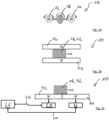
- Fig. 1A shows a motor system 10 with a first motor 12 and a second motor 14. Both motors 12, 14 drive the same axis 16 which in the example of Fig. 1A is a rotating axis.
- Fig. 1B also shows a motor system with a first and a second motor 12, 14.
- the two motors 12, 14 together move the axis 16, wherein the motors are linear motors and drive/move the axis 16 which is a carrier that is arranged between the two linear motors 12, 14.
- the two motors 12, 14 are linear motors that are arranged at the same side of an axis 16, which again is a carrier, wherein the two linear motors 12, 14 form a continuous track 18 for the axis 16.
- a first drive unit 20 which controls the first motor 12 and a second drive unit 22 which controls the second motor 14 is shown.
- the drive units 20, 22 can e.g. provide electrical power to the motors 12, 14 and receive position information on the axis 16 from the motors 12, 14.
- the motors 12, 14 can e.g. determine the position information using encoders and/or position magnets and the like (not shown).
- the drive units 20, 22 are connected via a field bus 24 (e.g. SERCOS, EIP, EtherCAT, etc.) to the motors 12, 14.
- the motion controller 26 could be connected via the field bus 24 to a PLC (not shown).
- the motors 12, 14 shown in Fig. 1A and Fig. 1B could be connected to drive units 20, 22.
- the drive units 20, 22 can be connected to the motors 12, 14 by motor power cables and encoder cables.
- the drive units 20, 22 can be integrated in the same housing as the coils of the linear motor 12, 14, wherein a wiring is internal.
- the motors shown in Fig. 1A-C all work together to drive the respective same axis 16.
- the drive units 20, 22 are configured to perform a closed loop control for driving the respective motors 12, 14, wherein the closed loop control of each of the drive units 20, 22 is based on the same control loop data set.
- Fig. 2 shows such a control loop data set 28 which in the Figures is also abbreviated as CLC (Control Loop Context).
- CLC Control Loop Context
- the control loop data set 28 is stored in the motion controller 26.
- the Control Loop Context 28 is a virtual concept, which may also happen inside of or distributed over the drive units 20, 22.
- a first control loop data set 28 (CLC1) is used to drive the first motor 12 and the second motor 14. As shown in Fig. 1A , the first and second motor 12, 14 drive the same rotational axis 16.
- the control loop data set 28 can be stored in the motion controller 26 and can synchronize the control loop data set 28 to the first drive unit 20 and the second drive unit 22.
- the control loop data set 28 is assigned to a control slot 30 (in the Figures also abbreviated as "CS").
- the control loop data set 28 is continuously synchronized so that the first drive unit 20 and the second drive unit 22 base their control of the motors 12, 14 on the same data in the control loop data set 28. In other words, the context of the motor control is synchronized.
- Fig. 2 also shows a further control loop data set 28 which relates to a different axis 16 with only one motor.
- This control loop data set 28 is also assigned to the second drive unit 22 but to a different controller slot 30. It is to be understood that the different control slots 30 in practice can work as different drive units although they may be executed on the same hardware.
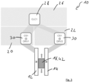
- Fig. 3 shows the motor arrangement of Fig. 1B , wherein the two motors 12, 14 are configured as linear motors.
- the control loop data set 28 is again distributed to the two drive units 20, 22 thereby moving the axis 16, i.e. the carrier, together.
- Fig. 4 shows an arrangement similar to Fig. 1C .
- Fig. 4 shows a third motor 32 which is controlled by a third drive unit 34.
- the motors 12, 14, 32 are again configured as linear motors and form a continuous track for the axes 16.
- Fig. 4 shows the carriers corresponding to the axes 16 which can be moved independently from each other. Such an arrangement can e.g. be used in the multi-carrier as shown in Figs. 5 and 6 (see below).
- One of the carriers is currently only in the area of the first motor 12, whereas another carrier is in the area of both the first motor 12 and the second motor 14.
- the carrier shown on the right of Fig. 4 is in the area of the second motor 14 and the third motor 32.
- a separate control loop data set 28 exists, in Fig. 4 also termed CLC1, CLC2 and CLC3.
- the control slot 30 of this axis (CLC1) is only assigned to the first drive unit 20.
- control loop data sets 28 for the two other axes 16 are assigned to the first drive unit 20 and the second drive unit 22 as well as to the second drive unit 22 and the third drive unit 34, respectively.
- CLC2 and CLC3 are each assigned to two different control slots 30.
- the first and second motor 12, 14 and the second and third motor 14, 32 can work together to achieve a smooth transition of the axes 16 between the different motors 12, 14, 32.
- the control of these axes 16 is then based on the same control loop data set 28, and thereby e.g. on the same position value.
- the drive unit 20, 22, 34 can each determine the current position value and relay the position value to the motion controller 26.
- the motion controller 26 can then calculate an average value for the position value and update the position value in the control loop data set 28 for the respective axis 16.
- a share value indicating the share part of driving an axis 16 can be changed over time as the axis 16 moves from one motor to another. For example, for the carrier shown in the middle in Fig. 4 a share value for the first drive unit could be 20% whereas a share value for the second drive unit 22 could be 80% (in the position shown in Fig. 4 ).
- the arrangement of motors 12, 14, 32 and drive units 20, 22, 34 as shown in Fig. 4 can be used in a multi-carrier system 36, as shown in Fig. 5 .
- the multi-carrier system 36 comprises a plurality of linear motors 38 which can be formed by the motors 12, 14 32 and which together form a continuous track 40.
- the track 40 forms a closed loop.
- a plurality of carriers 42 can be moved by the magnetic force of the linear motors 38.
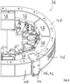
- Fig. 6 shows a detailed view of a curved section of the track 40, wherein the curved section comprises four linear motors 38.
- the carriers 42 comprise wheels 44 which allow movement along the track 40.
- the carriers 42 comprise a position magnet 46 which can be detected by the linear motors 38.
- the linear motors 38 and the respective drive units 20, 22, 34 feed the detected positions of the carriers 42 in the respective control loop data set 28 stored in the motion controller 26.
- control loop data set 28 can be stored and/or maintained in a different unit than the motion controller 26.
Landscapes
- Engineering & Computer Science (AREA)
- Power Engineering (AREA)
- Microelectronics & Electronic Packaging (AREA)
- Physics & Mathematics (AREA)
- Chemical & Material Sciences (AREA)
- Combustion & Propulsion (AREA)
- Electromagnetism (AREA)
- Control Of Multiple Motors (AREA)
Abstract
The present invention relates to a method for synchronously controlling a first motor and a second motor, wherein the first motor is controlled by a first drive unit, the second motor is controlled by a second drive unit, wherein the first motor and the second motor work together to drive the same axis and/or to move the same load, wherein the drive units each perform a closed loop control for driving the respective motor, wherein the closed loop control of each of the drive units is based on the same control loop data set.
Description
- The present invention relates to a method for synchronously controlling a first motor and a second motor, wherein the first motor is controlled by a first drive unit, the second motor is controlled by a second drive unit. The first motor and the second motor work together to drive the same axis and/or move the same load.
- There exist a number of applications in which two motors work together to drive the same axis and/or to move the same load. For example, a rotational load can be driven by two motors which are both coupled to the same rotating axis. Also, two linear motors can be arranged at opposite sides of a load that is moved by the two linear motors.
- Currently it is known to e.g. use one of the motors as a parent, wherein the corresponding drive unit sends position control or torque commands to a child motor/drive unit. Alternatively, it is also known to simply wire the two motors in parallel.
- However, in the parent/child solution, the specific parameters of the second/child motor cannot be taken fully into consideration. Particularly, only the parent motor is operating closed loop, resulting in lower performance of the child motor. The parallel wiring does not allow to take benefit from power scaling by using more than one motor/drive unit.
- The drawbacks for both these solultions ultimately lead to a reduced accuracy when driving the axis/moving the load. Also, problems can appear that the motor's forces do not add up but block each other or that - for linear motors - the load may tilt and become mechanically blocked. Finally, if different motors or motor sizes are used it is difficult to balance the motors accordingly.
- It is therefore the object of the present invention to provide a method for controlling at least two motors that allows an improved operation when the two motors work together to drive the same axis and/or move the same load.
- This object is satisfied by the method of
claim 1.Claim 1 teaches a method for synchronously controlling a first motor and a second motor, wherein the first motor is controlled by a first drive unit, the second motor is controlled by a second drive unit, wherein the first motor and the second motor work together to drive the same axis, i.e. a common axis, and/or to move the same load, i.e. a common load. According to the invention, the drive units each perform a closed loop control for driving the respective motor, wherein the closed loop control for each of the drive units is based on the same control loop data set. - When a drive unit controls the operation/movement of a motor, the drive unit e.g. evaluates the current position and/or speed of the axis and/or load and then correspondingly controls e.g. the voltage and/or currents supplied to the motor to a desired position and/or drive the motor with a desired speed, torque and/or force. The current position and/or speed of the motor can be detected e.g. with an encoder. Consequently, a detected or measured value relating to the operation of the motor is used to control the further operation of the motor. This is called a closed loop control. The data on which the closed loop control is based, e.g. the current position of the motor, the current torque and/or force supplied by the motor can be part of the control loop data set. Further or different data can of course also be part of the control loop data set.
- The invention is now based on the idea to use the same control loop data set for the closed loop control of each of the drive units. For example, all drive units base their (separate and/or individual) closed loop control on the same value for the position and/or speed of the axis. It was found that thereby a very reliable and accurate operation of multiple motors driving the same axis is possible.
- The control loop data set may be stored in a shared and/or synchronized memory.
- Each of the drive units is performing its own closed loop control of the motor that is connected to the respective drive unit. However, at least some of the input data for the closed loop control stems from the same control loop data set, i.e. some of the input data for the closed loop control of the different drive units is identical. Preferably, there exists only one control loop data set.
- It is to be understood that the data in the control loop data set can change over time, e.g. when the position or the speed of the axis changes. If a value in the control loop data set is changed, this change is effected in all drive units that then base their closed loop control on the changed value. It is beneficial that the different drive units - at a certain point in time - use the same data from the control loop data set.
- The drive units can e.g. be connected to a motion controller which provides drive commands to a number of drive units. The motion controller can in turn be connected to a PLC (Programmable Logic Controller) which supplies higher level commands to the motion controller. Also, the motion controller can be formed by a PLC or can comprise a PLC or can be comprised in a PLC. In some environments PLC and motion controller therefore can by synonyms. It is possible that different drive units are realized in one drive, i.e. on the same hardware. However, the operation of the different drive units may be separate.
- The control loop data set may be stored on any of the PLC, the motion controller or at least one of the drive units, wherein the different drive units may then access the control loop data set and/or regularly receive copies and/or updates of the control loop data set, as will be explained in more detail later.
- The control loop data set can also be termed a "control loop context" as the data in the data set provides the context or the control loops of the different drive units. By making the control loop data set available for a specific drive unit, the drive unit can also be termed a "control slot" which has the capability to perform an axis regulation.
- According to the invention, a higher accuracy and smoother operation can be achieved for motors working together to drive the same axis and/or move the same load. Furthermore, the concept of the invention is very flexible since the control loop data set can be made available to different drive units during operation (or in other words: one available control slot (i.e. a drive unit) can be assigned to a control loop context) and/or the control loop context can be assigned to a control slot.
- Thereby, the motors involved in driving an axis and/or moving a load can be changed dynamically during operation.
- It is to be understood that in the present technical field, the movement of a load is also referred to as the "driving of an axis". For example, if a linear motor moves a load, e.g. a carrier, this can also be termed "driving of an axis", wherein the carrier is the axis. The position and speed of the carrier are then the position and speed of the axis. Consequently, when it is herein referred to the driving of an axis, this also always means the movement of a load.
- Further embodiments of the invention are disclosed in the description, the figures and the claims.
- According to a first embodiment, the drive units directly or indirectly access the same memory which stores the control loop data set. The memory can be installed on one of the drive units, on the motion controller and/or on a different entity. The drive units may be connected to the entity having the memory via a data link, e.g. a data bus or field bus. The direct access to the memory which stores the control data set would be performed, e.g. if the control loop data set is stored on a motion controller or on one of the drive units, wherein the drive units (or the other drive units) then regularly access the memory to download the updated data from the control loop data set. An indirect access would be that the control loop data set is regularly distributed to the drive units, wherein each drive unit stores its own copy of the (regularly updated) control loop data set.
- According to a further embodiment the control loop data set is repeatedly synchronized between the drive units. Preferably, the drive units synchronize the control loop data set self-organized, after a step of making the drive units knowing each other. The drive units may make the control loop data set accessible for the motion controller. The repeated synchronization between the drive units assures that the closed loop control of the drive units is based on the same data of the control loop data set. Thereby a mirroring of the memory which stores the control loop data set may be performed. The synchronization can be performed e.g. in predefined time intervals, e.g. at least every 10 milliseconds, every millisecond or every 0,5 milliseconds. The synchronization can also be event-based, i.e. occur when a change in the control loop data set occurs.
- In general, the same values, preferably at one point in time, are used for the closed control loop within different drive units.
- According to further embodiment the control loop data set comprises a position and/or a speed value and/or an acceleration value of the axis and/or the load. All the mentioned values can be values of the current point in time, i.e. up to date values. The values in the control loop data set can be updated e.g. at least every 10 milliseconds, every 1 millisecond or every 0,5 milliseconds.
- According to a further embodiment, the control loop data set comprises one or more of the following:
- a mass value of the axis and/or of the load;
- an inertia value of the axis and/or of the load;
- a friction and/or resistance value of the axis and/or of the load;
- gain factors used for the closed loop control within the drive units.
- Again, the aforementioned values can be current/up to date values which can be updated in the time intervals given above.
- The values in the control loop data set help keep the closed loop control over different drive units consistent, yielding a more stable and accurate control of the axis.
- According to a further embodiment, at least some of the values in the control loop data set are updated by one or more of the drive units. The drive units can e.g. be configured to determine or to measure at least one of the values in the control loop data set. If a determined/measured value of one of the drive units differs from the value stored in the control loop data set, the value in the control loop data set can be updated based on the new determined/measured value. For example, one of the drive units may send the updated value to a motion controller or a PLC, i.e. to a supervising unit. The supervising unit can be any unit, e.g. one of the drive units, the motion controller, the PLC etc. The supervising unit can, after receiving an updated value, update the control loop data set.
- According to a further embodiment, an updated value for the control loop data set is based on, preferably measured, data from at least two of the drive units, wherein data from the different drive units is preferably averaged or weighted to yield the updated value. By taking into account the values determined or measured by different drive units it has been found that an even higher accuracy of driving the axis can be achieved. For example, the sensors of the different drive units measuring a value, e.g. a position value of the axis, can be arranged at different positions along the axis and can thereby provide an e.g. averaged value that resembles more closely the true state of the axis.
- According to a further embodiment, the drive units, in addition to the control loop data set, use internal control loop data which may be different for different drive units for performing the closed loop control, wherein the internal control loop data preferably comprises voltage and/or current values for the motor controlled by the respective drive unit. The closed loop control of a motor can thus be based on the one hand on the data from the control loop data set and on the other hand on the internal control loop data. The internal control loop data comprises data that is unique for each motor and/or drive unit. For example, the voltage currently supplied to the motor and/or the current currently supplied to the motor can be part of the internal control loop data. Furthermore, a motor type, further motor parameters, etc. can be part of the internal control loop data. The control loop data is necessary to accommodate the closed control loop to the specific motor, thereby allowing e.g. the use of different motors to drive the same axis.
- According to a further embodiment, at least one of the drive units is assigned a share value which indicates the share of driving the axis and/or moving the load of the respective motor. In other words, the power, torque and/or force required to drive an axis can be distributed over different motors by using the share value. A lower share value indicates that the respective motor plays a smaller part in driving the respective axis. For example, the drive unit may reduce the power, torque and/or force supplied by the motor based on the share value. The share value can indicate which percentage of the power, torque and/or force of a motor is actually provided by the motor as compared to which power, torque and/or force the motor would provide only based on the control loop data set and/or the internal control loop data. Consequently, the share value can be between 0% and 100% but could also exceed 100% if a motor should be driven above its usual limitations.
- According to a further embodiment, the share value is set dependent on the speed of the axis, dependent on the torque and/or the power consumption of one of the motors, dependent on the position of the axis and/or the load and/or is set manually. In other words, the share value for one or more of the drive units can be set dynamically and particularly can be set depending on another value (e.g. based on position or speed of the axis). For example, if it is known that the first motor is performing better at lower speeds, wherein the second motor is performing better at higher speeds, the share value can be set higher for the first motor at lower speeds, wherein at higher speeds the share value of the first motor is reduced and the share value of the second motor is increased.
- Additionally or alternatively, the share value can be shifted linearly, for example over time and/or based on the position of the axis. Also, the share value can remain constant.
- Furthermore, it is also possible to set the share value manually. For example in case one of the motors need to be replaced during maintenance, the share value of the drive unit of the respective motor can be reduced to zero. The motor can then be replaced. After replacing the motor, the share value can then be increased. Thereby, the maintenance can be simplified since only the share value needs be changed, whereas the operation of the axis can continue without interruption.
- Preferably, the share values for the different drive units can be set such that the combined share values amount to a predefined value or exceed the predetermined value at any given point of time.
- A share value of 100% or if no share value is assigned to a drive unit means that the drive unit and the motor are performing "normally", i.e. based on the control loop data set and/or the internal control loop data as described above.
- According to a further embodiment, a third motor is controlled by a third drive unit, wherein the third motor drives the same axis and/or moves the same load as the first and/or second motor. Preferably, the drive unit performs a closed loop control for driving the third motor, wherein the closed loop control of the third drive unit is based on the control loop data set. Further preferably, the third motor starts driving the axis and/or moving the load when the first and/or second motor are already driving the axis and/or moving the load. Alternatively or additionally, the first and/or second motor stop driving the axis and/or moving the load, wherein one of the other motors continues driving the axis and/or moving the load. In other words, one of the first and second motor can stop supporting the driving of the axis, wherein another motor, namely the third motor, begins supporting the movement of the axis.
- This can be particularly helpful if several linear motors are arranged one after the other to form a track (as in the multi-carrier system described below) wherein the load (i.e. the axis) moves from one linear motor to the other. For example, first, only the first motor can drive the axis, then for a certain amount of time the first and the second motor can drive the axis together, when the load is in an area between the first and second motor. When the load is then only in the area of the second motor, the first motor can stop supporting the movement. When the load then reaches an area where it can be driven by the second and third motor, the third motor can start moving the load/driving the axis so that a continuous movement of the load can be achieved.
- Such a transition can be easily achieved by simply sharing the control loop data set firstly with the first and second motor, i.e. with the first and second drive unit, and then later sharing the control loop data set with the second and third drive unit. Other than sharing the control loop data set it is also possible to distribute the control loop data set to the respective drive units or to allow access to the control loop data set for the respective drive units, as described above, e.g. by a mirrored memory. In other words, the control loop data set can be assigned to a control slot, e.g. firstly to the first drive unit of the first motor. When the load can be driven by the first and the second motor, the control loop data set (i.e. the control loop context) can be assigned simultaneously to two control slots, namely the first drive unit and the second drive unit. Later, the control loop data set can be assigned to the second and third drive unit.
- Alternatively or additionally, the transitioning from one drive unit to another can also be achieved by changing the share factors of the respective drive units. For example, when the load more and more is in the area of the second drive unit, the share factor of the first drive unit can be decreased (e.g. linearly or based on the position of the load) to 0%. Similarly, when the load reaches the area where it can be driven by the third motor, the share factor of the third drive unit and thus of the third motor can be increased (e.g. linearly or based on the position of the load).
- Thereby, the operation of different loads along a track of linear motors can be greatly simplified since a control loop data set (or "control loop context") for each load can simply be assigned to different drive units as the load moves along the track.
- It is to be understood that also only three motors are mentioned here, an even higher number of motors could be used to drive the same axis and/or move the same load.
- The invention also relates to a motor system comprising a first motor and a second motor, a first drive unit and a second drive unit as well as a driven axis or a moved load, wherein the first motor is controlled by the first drive unit, the second motor is controlled by the second drive unit, wherein the first motor and the second motor work together to drive the axis and/or to move the load, wherein the drive units each are configured to perform a closed loop control for driving the respective motor, wherein the closed loop control of each of the drive units is based on the same control loop data set.
- As disclosed above, the motor system can also comprise a third motor and a third drive unit, which controls the third motor.
- The drive units may be connected, e.g. via a data bus or field bus (e.g. Sercos, EIP, EtherCAT and the like), to a motion controller. The motion controller, in turn, may be connected to a PLC, wherein the PLC controls the motion controller and the motion controller controls the drive units.
- According to an embodiment of the motor system, at least one of the motors is a rotating motor or a linear motor, wherein preferably two of the motors are linear motors that are arranged on different sides of the load or are arranged one after another to form a continuous track for the load. In case one or more of the motors are rotating motors, the motors can drive a rotating axis. For linear motors, the axis can be a load that moves along the track formed by the linear motors. The linear motors may be arranged on different or opposite sides of the load. In this arrangement, due to the use of the same control loop data set a tilting and thus mechanical blocking of the load can be prevented. For linear motors arranged one after another, the transitioning between distinct drive units and/or motors can be simplified.
- The invention further relates to a multi-carrier system comprising a plurality of linear motors, the linear motors are arranged along a track, the track preferably forming a closed loop, wherein a plurality of carriers are arranged at the track and are independently movable along the track by the linear motors, wherein at least two (or all) of the linear motors are part of a motor system as described above.
- Each of the carriers can be a separate axis (i.e. load). The carriers can comprise a permanent magnet to allow the linear motors to move the carriers by producing a magnetic field.
- The different linear motors of the multi-carrier can be arranged directly next to each other to form the continuous track which is closed in itself and thus forms a closed loop. Each of the carriers can be moved independently of other carriers.
- In particular for the multi-carrier but also in general, for each axis (i.e. for each carrier) a separate control loop data set can be maintained. Accordingly, at least two or more control loop data sets can be used for different axes. The separate control loop data sets for the separate carriers can e.g. comprise the respective current information on the position, speed, acceleration and/or weight of the respective carrier.
- When one of the carriers is moving along the track, the control loop data set of the respective carrier can be made available or assigned to the drive unit or drive units which currently can drive the carrier, as the carrier is in the section of the track in which the respective linear motor can produce a magnetic field to drive the carrier. Thus, for the multi-carrier system but also for other systems comprising two neighboring linear motors, the control loop data set for the axis/carrier can be used by two drive units at the same time. Later, only one drive unit uses the control loop data set, when the axis has moved out of a transitioning area between the two motors. When the axis (i.e. the carrier) then moves into the next transitioning area between two linear motors, the control loop data set can then be assigned to these two linear motors. In other words, the control loop data set can alternatingly be used by two drive units and then by only one drive unit.
- The disclosure with respect to the method of the invention is also valid for the motor system and the multi-carrier system. This is particularly true for embodiments and advantages. Further, it is to be understood that all features and embodiments disclosed herein can be combined if not explicitly stated otherwise.
- Various features and advantages of the present invention will become more apparent from the following exemplary description and the examples shown in the accompanying drawings, wherein:
- Fig. 1A to 1C
- show different motor arrangements of two motors driving the same axis/load;
- Fig. 2
- shows the use of the same control loop data set in different drive units for rotational motors;
- Fig. 3
- shows the use of the same control loop data set for two linear motors arranged on opposite sides of a load;
- Fig. 4
- shows the use of different control loop data sets for linear motors arranged along a common track;
- Fig. 5
- shows a multi-carrier system in a schematic view; and
- Fig. 6
- shows a curved section of the multi-carrier of
Fig. 5 in more detail. -
Fig. 1A shows amotor system 10 with afirst motor 12 and asecond motor 14. Bothmotors same axis 16 which in the example ofFig. 1A is a rotating axis. - The example of
Fig. 1B also shows a motor system with a first and asecond motor Fig. 1B the twomotors axis 16, wherein the motors are linear motors and drive/move theaxis 16 which is a carrier that is arranged between the twolinear motors - In
Fig. 1C , again, the twomotors axis 16, which again is a carrier, wherein the twolinear motors continuous track 18 for theaxis 16. - In
Fig. 1C afirst drive unit 20 which controls thefirst motor 12 and asecond drive unit 22 which controls thesecond motor 14 is shown. Thedrive units motors axis 16 from themotors motors drive units motors motion controller 26 could be connected via thefield bus 24 to a PLC (not shown). - In the same manner as shown in
Fig. 1C , also themotors Fig. 1A and Fig. 1B could be connected to driveunits rotational motors Fig. 1A , thedrive units motors linear motors 12, 14 (e.g. as in the multi-carrier ofFigs. 5 and6 ), thedrive units linear motor - The motors shown in
Fig. 1A-C all work together to drive the respectivesame axis 16. - The
drive units respective motors drive units -
Fig. 2 shows such a control loop data set 28 which in the Figures is also abbreviated as CLC (Control Loop Context). InFig. 2 the control loop data set 28 is stored in themotion controller 26. However, it is to be understood that this is merely an example and that theControl Loop Context 28 is a virtual concept, which may also happen inside of or distributed over thedrive units - A first control loop data set 28 (CLC1) is used to drive the
first motor 12 and thesecond motor 14. As shown inFig. 1A , the first andsecond motor rotational axis 16. As an example, the control loop data set 28 can be stored in themotion controller 26 and can synchronize the control loop data set 28 to thefirst drive unit 20 and thesecond drive unit 22. In thefirst drive unit 20 the control loop data set 28 is assigned to a control slot 30 (in the Figures also abbreviated as "CS"). The control loop data set 28 is continuously synchronized so that thefirst drive unit 20 and thesecond drive unit 22 base their control of themotors loop data set 28. In other words, the context of the motor control is synchronized. - As an addition,
Fig. 2 also shows a further control loop data set 28 which relates to adifferent axis 16 with only one motor. This control loop data set 28 is also assigned to thesecond drive unit 22 but to adifferent controller slot 30. It is to be understood that thedifferent control slots 30 in practice can work as different drive units although they may be executed on the same hardware. -
Fig. 3 shows the motor arrangement ofFig. 1B , wherein the twomotors drive units axis 16, i.e. the carrier, together. -
Fig. 4 shows an arrangement similar toFig. 1C . In addition toFig. 1C ,Fig. 4 shows a third motor 32 which is controlled by athird drive unit 34. Themotors axes 16.Fig. 4 shows the carriers corresponding to theaxes 16 which can be moved independently from each other. Such an arrangement can e.g. be used in the multi-carrier as shown inFigs. 5 and6 (see below). - One of the carriers is currently only in the area of the
first motor 12, whereas another carrier is in the area of both thefirst motor 12 and thesecond motor 14. The carrier shown on the right ofFig. 4 is in the area of thesecond motor 14 and the third motor 32. For each of the carriers, i.e. for each of theaxes 16, a separate control loop data set 28 exists, inFig. 4 also termed CLC1, CLC2 and CLC3. As theaxis 16 shown on the left ofFig. 4 is only in the area of thefirst motor 12, thecontrol slot 30 of this axis (CLC1) is only assigned to thefirst drive unit 20. However, the control loop data sets 28 for the twoother axes 16 are assigned to thefirst drive unit 20 and thesecond drive unit 22 as well as to thesecond drive unit 22 and thethird drive unit 34, respectively. In other words, CLC2 and CLC3 are each assigned to twodifferent control slots 30. - Due to the assignment to two
different control slots 30 the first andsecond motor third motor 14, 32 can work together to achieve a smooth transition of theaxes 16 between thedifferent motors axes 16 is then based on the same control loop data set 28, and thereby e.g. on the same position value. Thedrive unit motion controller 26. Themotion controller 26 can then calculate an average value for the position value and update the position value in the control loop data set 28 for therespective axis 16. Also, a share value indicating the share part of driving anaxis 16 can be changed over time as theaxis 16 moves from one motor to another. For example, for the carrier shown in the middle inFig. 4 a share value for the first drive unit could be 20% whereas a share value for thesecond drive unit 22 could be 80% (in the position shown inFig. 4 ). - The arrangement of
motors units Fig. 4 can be used in amulti-carrier system 36, as shown inFig. 5 . Themulti-carrier system 36 comprises a plurality oflinear motors 38 which can be formed by themotors continuous track 40. Thetrack 40 forms a closed loop. Along the track a plurality of carriers 42 can be moved by the magnetic force of thelinear motors 38. -
Fig. 6 shows a detailed view of a curved section of thetrack 40, wherein the curved section comprises fourlinear motors 38. As can be seen inFig. 6 the carriers 42 comprisewheels 44 which allow movement along thetrack 40. The carriers 42 comprise aposition magnet 46 which can be detected by thelinear motors 38. Thelinear motors 38 and therespective drive units motion controller 26. - Additional or different values other than the position values can be present and updated in the control
loop data set 28. Also, the control loop data set 28 can be stored and/or maintained in a different unit than themotion controller 26. - Due to the use of the same data from the control loop data set 28 to control the
same axis 16 withdifferent motors motors -
- 10
- motor system
- 12
- first motor
- 14
- second motor
- 16
- axis
- 18
- track
- 20
- first drive unit
- 22
- second drive unit
- 24
- field bus
- 26
- motion controller
- 28
- control loop data set
- 30
- control slot
- 32
- third motor
- 34
- third drive unit
- 36
- multi-carrier system
- 38
- linear motor
- 40
- track
- 42
- carrier
- 44
- wheel
- 46
- position magnet
Claims (14)
- A method for synchronously controlling a first motor (12) and a second motor (14),wherein the first motor (12) is controlled by a first drive unit (20), the second motor (14) is controlled by a second drive unit (22),wherein the first motor (12) and the second motor (14) work together to drive the same axis (16. 42) and/or to move the same load (16, 42),wherein the drive units (20, 22, 34) each perform a closed loop control for driving the respective motor, wherein the closed loop control of each of the drive units (20, 22, 34) is based on the same control loop data set (28).
- The method of claim 1,
wherein the drive units (20, 22, 34) directly or indirectly access the same memory which stores the control loop data set (28). - The method of at least one of claims 1 or 2,
wherein the control loop data set (28) is repeatedly synchronized between the drive units (20, 22, 34). - The method of at least one of the preceding claims,
wherein the control loop data set (28) comprises a position and/or a speed value and/or an acceleration value of the axis (16, 42) and/or of the load (16, 42). - The method of at least one of the preceding claims,
wherein the control loop data set (28) comprises one or more of the following- a mass value of the axis (16, 42) and/or of the load (16, 42);- an inertia value of the axis (16, 42) and/or of the load (16, 42);- a friction and/or resistance value of the axis (16, 42) and/or of the load (16, 42);- gain factors used for the closed loop control within the drive units (20, 22, 34). - The method of at least one of the preceding claims,
wherein at least some of the values in the control loop data set (28) are updated by the drive units (20, 22, 34). - The method of claim 6,
wherein an updated value for the control loop data set is based on data from two of the drive units (20, 22, 34), wherein the data from the different drive units (20, 22, 34) is preferably averaged or weighted to yield the updated value. - The method of at least one of the preceding claims,
wherein the drive units (20, 22, 34), in addition to the control loop data set (28), use internal control loop data which is different for different drive units (20, 22, 34) for performing the closed loop control, wherein the internal control loop data preferably comprises voltage and/or current values for the motor controlled by the respective drive unit. - The method of at least one of the preceding claims,
wherein at least one of the drive units (20, 22, 34) is assigned a share value which indicates the share of driving the axis (16, 42) and/or moving the load (16, 42) of the respective motor (12, 14, 32). - The method of claim 9,
wherein the share value is set dependent on the speed of the axis (16, 42), dependent on the torque and/or the power consumption of one of the motors (12, 14, 32), dependent on the position of the axis (16, 42) and/or the load (16, 42) and/or is set manually. - The method of at least one of the preceding claims,wherein a third motor (32) is controlled by a third drive unit (34), wherein the third motor drives the same axis (16, 42) and/or moves the same load (16, 42) as the first and/or second motor (12, 14), wherein the third drive unit (34) performs a closed loop control for driving the third motor (32), wherein the closed loop control of the third drive unit (34) is based on the control loop data set (28),wherein preferably the third motor (32) starts driving the axis (16, 42) and/or moving the load (16, 42) when the first and/or second motor (12, 14) are already driving the axis (16, 42) and/or moving the load (16, 42)
and/orwherein preferably the first and/or second motor (12, 14) stop driving the axis (16, 42) and/or moving the load (16, 42), wherein one of the other motors continues driving the axis (16, 42) and/or moving the load (16, 42). - A motor system (10) comprising a first motor (12) and a second motor (14), a first drive unit (20) and a second drive unit (22) as well as a driven axis (16, 42) or a moved load (16, 42),wherein the first motor (12) is controlled by the first drive unit (20), the second motor (14) is controlled by the second drive unit (22),wherein the first motor (12) and the second motor (14) work together to drive the axis (16, 42) and/or to move the load (16, 42),wherein the drive units (20, 22, 34) each are configured to perform a closed loop control for driving the respective motor (12, 14, 32), wherein the closed loop control of each of the drive units (20, 22, 34) is based on the same control loop data set (28).
- The motor system of claim 12,
wherein at least one of the motors (12, 14, 32) is a rotating motor or a linear motor (38), wherein preferably two of the motors (12, 14, 32) are linear motors (38) that are arranged on different sides of the load (16, 42) or are arranged one after another to form a continuous track (40) for the load (16, 42). - A multicarrier system (36) comprising a plurality of linear motors, the linear motors are arranged along a track (40), the track (40) preferably forming a closed loop, wherein a plurality of carriers (42) are arranged at the track (40) and are independently movable along the track (40) by the linear motors (38), wherein at least two of the linear motors (38) are part of a motor system (10) in accordance with claim 12 or claim 13.
Priority Applications (3)
| Application Number | Priority Date | Filing Date | Title |
|---|---|---|---|
| EP23306295.9A EP4498594A1 (en) | 2023-07-26 | 2023-07-26 | Method for synchronously controlling two motors |
| CN202410994423.3A CN119382545A (en) | 2023-07-26 | 2024-07-24 | Method for synchronously controlling two motors |
| US18/783,822 US20250038682A1 (en) | 2023-07-26 | 2024-07-25 | Method for synchronously controlling two motors |
Applications Claiming Priority (1)
| Application Number | Priority Date | Filing Date | Title |
|---|---|---|---|
| EP23306295.9A EP4498594A1 (en) | 2023-07-26 | 2023-07-26 | Method for synchronously controlling two motors |
Publications (1)
| Publication Number | Publication Date |
|---|---|
| EP4498594A1 true EP4498594A1 (en) | 2025-01-29 |
Family
ID=87557561
Family Applications (1)
| Application Number | Title | Priority Date | Filing Date |
|---|---|---|---|
| EP23306295.9A Pending EP4498594A1 (en) | 2023-07-26 | 2023-07-26 | Method for synchronously controlling two motors |
Country Status (3)
| Country | Link |
|---|---|
| US (1) | US20250038682A1 (en) |
| EP (1) | EP4498594A1 (en) |
| CN (1) | CN119382545A (en) |
Citations (3)
| Publication number | Priority date | Publication date | Assignee | Title |
|---|---|---|---|---|
| US5767635A (en) * | 1993-06-04 | 1998-06-16 | Sihi Gmbh & Co. Kg | Displacement machine with electronic motor synchronization |
| US20190078950A1 (en) * | 2017-09-13 | 2019-03-14 | Magnemotion, Inc. | Method and Apparatus to Characterize Loads in a Linear Synchronous Motor System |
| US20220173646A1 (en) * | 2020-11-27 | 2022-06-02 | Schneider Electric Industries Sas | Linear motor system and method for operating |
Family Cites Families (4)
| Publication number | Priority date | Publication date | Assignee | Title |
|---|---|---|---|---|
| TWI242490B (en) * | 2003-12-12 | 2005-11-01 | Ind Tech Res Inst | Servo motor control apparatus for electric injection molding machine |
| KR100902480B1 (en) * | 2006-11-08 | 2009-06-11 | 엘에스엠트론 주식회사 | Apparatus and Method of Controlling Injection in the Electric Injection Molding Machine |
| US10175065B2 (en) * | 2016-02-02 | 2019-01-08 | Honeywell International Inc. | Near-zero revolutions per minute (RPM) sensing |
| EP3955436B1 (en) * | 2020-08-14 | 2024-01-17 | Schneider Electric Industries SAS | Linear motor system and operating method for same |
-
2023
- 2023-07-26 EP EP23306295.9A patent/EP4498594A1/en active Pending
-
2024
- 2024-07-24 CN CN202410994423.3A patent/CN119382545A/en active Pending
- 2024-07-25 US US18/783,822 patent/US20250038682A1/en active Pending
Patent Citations (3)
| Publication number | Priority date | Publication date | Assignee | Title |
|---|---|---|---|---|
| US5767635A (en) * | 1993-06-04 | 1998-06-16 | Sihi Gmbh & Co. Kg | Displacement machine with electronic motor synchronization |
| US20190078950A1 (en) * | 2017-09-13 | 2019-03-14 | Magnemotion, Inc. | Method and Apparatus to Characterize Loads in a Linear Synchronous Motor System |
| US20220173646A1 (en) * | 2020-11-27 | 2022-06-02 | Schneider Electric Industries Sas | Linear motor system and method for operating |
Also Published As
| Publication number | Publication date |
|---|---|
| US20250038682A1 (en) | 2025-01-30 |
| CN119382545A (en) | 2025-01-28 |
Similar Documents
| Publication | Publication Date | Title |
|---|---|---|
| US10454355B2 (en) | Long stator linear motor and method for moving a transport unit of a long stator linear motor | |
| US9958852B2 (en) | Multi-mover linear motor controller providing shared coordination subsystem | |
| KR100462092B1 (en) | Stepping motor control device | |
| CN113625657B (en) | Motion control method and device based on electronic cam curve | |
| WO2010113161A1 (en) | Apparatus and method for optimizing current use during control of multiple motors | |
| CA3009902A1 (en) | Method for operating a transport apparatus in the form of a long stator linear motor | |
| CN1086859A (en) | Warp knitting machine | |
| CN111030552B (en) | Synchronous control method of servo driver and servo driver | |
| EP4375777A1 (en) | System and method for mover self-navigation in an independent cart system | |
| US12151905B2 (en) | Electromagnetic transport system | |
| WO1998050760A2 (en) | Modular conveyor system having multiple moving elements under independent control | |
| US20250038682A1 (en) | Method for synchronously controlling two motors | |
| WO2024000711A1 (en) | Control method for multi-rotor direct drive transmission system and related device | |
| US4769580A (en) | Electromagnetic linear drive | |
| JP2000501279A (en) | Control device for device driven by linear motor | |
| US12091265B2 (en) | Method of operating a transport system and transport system | |
| US4908562A (en) | Method and apparatus for controlling the magnitude and direction of a current through a winding | |
| JP2025023077A (en) | Transport system, control system and control method | |
| US20200379439A1 (en) | Automated Independent Cart System and Method of Controlling Operation of a Plurality of movers of the Automated Independent Cart System | |
| AU647427B2 (en) | potion control | |
| CN120722844B (en) | Multi-motor control method | |
| GB2410572A (en) | A method of controlling a processing base | |
| CN118473283B (en) | High-speed pulse train output, monitoring and control method | |
| WO2022185830A1 (en) | Motor system | |
| RU2859965C1 (en) | Control device for multi-channel electromechanical steering gear |
Legal Events
| Date | Code | Title | Description |
|---|---|---|---|
| PUAI | Public reference made under article 153(3) epc to a published international application that has entered the european phase |
Free format text: ORIGINAL CODE: 0009012 |
|
| STAA | Information on the status of an ep patent application or granted ep patent |
Free format text: STATUS: REQUEST FOR EXAMINATION WAS MADE |
|
| 17P | Request for examination filed |
Effective date: 20241126 |
|
| AK | Designated contracting states |
Kind code of ref document: A1 Designated state(s): AL AT BE BG CH CY CZ DE DK EE ES FI FR GB GR HR HU IE IS IT LI LT LU LV MC ME MK MT NL NO PL PT RO RS SE SI SK SM TR |
|
| STAA | Information on the status of an ep patent application or granted ep patent |
Free format text: STATUS: EXAMINATION IS IN PROGRESS |
|
| 17Q | First examination report despatched |
Effective date: 20251013 |