EP4498573A1 - An electric motor and a method for assembling an electric motor - Google Patents
An electric motor and a method for assembling an electric motor Download PDFInfo
- Publication number
- EP4498573A1 EP4498573A1 EP23187522.0A EP23187522A EP4498573A1 EP 4498573 A1 EP4498573 A1 EP 4498573A1 EP 23187522 A EP23187522 A EP 23187522A EP 4498573 A1 EP4498573 A1 EP 4498573A1
- Authority
- EP
- European Patent Office
- Prior art keywords
- stator
- contact surfaces
- electric motor
- machining
- stator frame
- Prior art date
- Legal status (The legal status is an assumption and is not a legal conclusion. Google has not performed a legal analysis and makes no representation as to the accuracy of the status listed.)
- Pending
Links
Images


Classifications
-
- H—ELECTRICITY
- H02—GENERATION; CONVERSION OR DISTRIBUTION OF ELECTRIC POWER
- H02K—DYNAMO-ELECTRIC MACHINES
- H02K1/00—Details of the magnetic circuit
- H02K1/06—Details of the magnetic circuit characterised by the shape, form or construction
- H02K1/12—Stationary parts of the magnetic circuit
- H02K1/18—Means for mounting or fastening magnetic stationary parts on to, or to, the stator structures
- H02K1/185—Means for mounting or fastening magnetic stationary parts on to, or to, the stator structures to outer stators
-
- H—ELECTRICITY
- H02—GENERATION; CONVERSION OR DISTRIBUTION OF ELECTRIC POWER
- H02K—DYNAMO-ELECTRIC MACHINES
- H02K1/00—Details of the magnetic circuit
- H02K1/06—Details of the magnetic circuit characterised by the shape, form or construction
- H02K1/12—Stationary parts of the magnetic circuit
- H02K1/18—Means for mounting or fastening magnetic stationary parts on to, or to, the stator structures
-
- H—ELECTRICITY
- H02—GENERATION; CONVERSION OR DISTRIBUTION OF ELECTRIC POWER
- H02K—DYNAMO-ELECTRIC MACHINES
- H02K1/00—Details of the magnetic circuit
- H02K1/06—Details of the magnetic circuit characterised by the shape, form or construction
- H02K1/12—Stationary parts of the magnetic circuit
- H02K1/16—Stator cores with slots for windings
-
- H—ELECTRICITY
- H02—GENERATION; CONVERSION OR DISTRIBUTION OF ELECTRIC POWER
- H02K—DYNAMO-ELECTRIC MACHINES
- H02K15/00—Processes or apparatus specially adapted for manufacturing, assembling, maintaining or repairing of dynamo-electric machines
- H02K15/02—Processes or apparatus specially adapted for manufacturing, assembling, maintaining or repairing of dynamo-electric machines of stator or rotor bodies
-
- H—ELECTRICITY
- H02—GENERATION; CONVERSION OR DISTRIBUTION OF ELECTRIC POWER
- H02K—DYNAMO-ELECTRIC MACHINES
- H02K15/00—Processes or apparatus specially adapted for manufacturing, assembling, maintaining or repairing of dynamo-electric machines
- H02K15/12—Impregnating, moulding insulation, heating or drying of windings, stators, rotors or machines
-
- H—ELECTRICITY
- H02—GENERATION; CONVERSION OR DISTRIBUTION OF ELECTRIC POWER
- H02K—DYNAMO-ELECTRIC MACHINES
- H02K15/00—Processes or apparatus specially adapted for manufacturing, assembling, maintaining or repairing of dynamo-electric machines
- H02K15/14—Casings; Enclosures; Supports
-
- H—ELECTRICITY
- H02—GENERATION; CONVERSION OR DISTRIBUTION OF ELECTRIC POWER
- H02K—DYNAMO-ELECTRIC MACHINES
- H02K15/00—Processes or apparatus specially adapted for manufacturing, assembling, maintaining or repairing of dynamo-electric machines
-
- H—ELECTRICITY
- H02—GENERATION; CONVERSION OR DISTRIBUTION OF ELECTRIC POWER
- H02K—DYNAMO-ELECTRIC MACHINES
- H02K2213/00—Specific aspects, not otherwise provided for and not covered by codes H02K2201/00 - H02K2211/00
- H02K2213/03—Machines characterised by numerical values, ranges, mathematical expressions or similar information
-
- H—ELECTRICITY
- H02—GENERATION; CONVERSION OR DISTRIBUTION OF ELECTRIC POWER
- H02K—DYNAMO-ELECTRIC MACHINES
- H02K2215/00—Specific aspects not provided for in other groups of this subclass relating to methods or apparatus specially adapted for manufacturing, assembling, maintaining or repairing of dynamo-electric machines
-
- H—ELECTRICITY
- H02—GENERATION; CONVERSION OR DISTRIBUTION OF ELECTRIC POWER
- H02K—DYNAMO-ELECTRIC MACHINES
- H02K5/00—Casings; Enclosures; Supports
- H02K5/24—Casings; Enclosures; Supports specially adapted for suppression or reduction of noise or vibrations
Definitions
- This invention relates to an electric motor and a method for assembling an electric motor.
- the motor components are typically manufactured separately and assembled first into several separate sub-entities forming the structural base units of the motor.
- These structural base units include, for example, the stator and rotor assemblies, as well as the stator frame.
- These separate sub-entities are then assembled into the final motor unit during later steps of the manufacturing process.
- the final motor assembly is typically performed using both shrink fit connection and mechanical connector elements between the sub-entities, such that reception points for the mechanical connector elements need to be prepared and carefully positioned at corresponding connecting surfaces at each of the sub-entities to be assembled.
- a challenge related to electric motors is that even very small deviations in the dimensions or mutual locations of the components of the electric motor may have a significant impact on the properties and performance of the motor. Problems in the form of vibrations may occur, in case the components of the electric motor have not been rigidly attached to each other at exactly the correct mutual positions.
- An object of the present invention is to solve the above-mentioned drawbacks and to provide a solution for simplified electric motor assembly and robust connection between a stator and a stator frame. These objects are achieved with a method according to independent claim 1 and an electric motor according to independent claim 5.
- stator frame and stator may be machined separately to conveniently provide a robust connection between the stator and the stator frame.
- Figure 1 illustrates one embodiment of an electric motor 1, wherein a rotor included in the motor assembly has been faded out and is only presented with a dashed line, so as to more clearly illustrate the other structural units of the motor.
- the electric motor 1 comprises a stator 2 operationally connecting to the rotor 3 for providing torque to it, in other words such that in operation, a magnetic field is created in the stator 2 to generate torque to a shaft of the rotor and causing it to rotate.
- the rotor 3 in said example is arranged inside the stator 2 to be coaxial with it, and it may represent, for example, any rotor construction known from prior art.
- the electric motor 1 also comprises a stator frame 5 surrounding the stator 2, wherein in the example of Figure 1 the stator frame 5 comprises two intermediate plates 6 having coaxially aligned openings 7 for receiving the stator 2. Said intermediate plates 6 are in the example arranged between frame end shields 101, 102, and extend in a substantially perpendicular direction with respect to the longitudinal direction of the stator 2 and the rotor 3. In other embodiments of the electric motor 1, the number and positioning of the intermediate plates 6 may also deviate from the example of Figure 1 , such that also a plurality of intermediate plates 6 may be included in the construction.
- Figure 2 illustrates a stator core assembly of the electric motor 1 of Figure 1 as separated from the rest of the motor construction.
- the outer perimeter of the stator 2 which in this case corresponds to the circumference of the cylindrically shaped stator 2, is provided with beams 4 extending in a longitudinal direction of the stator 2.
- Said beams 4 may be used for, for example, binding together laminations forming the core of the stator 2 and to provide added rigidity to the stator construction, and their number as well as positioning at the outer perimeter of the stator 2 may deviate from the example of Figure 2 in other embodiments of the electric motor 1.
- Figure 3 illustrates a crosscut section of the electric motor 1 of Figure 1 in a direction perpendicular to the longitudinal direction of the stator 2.
- the at least two intermediate plates 6 of the stator frame comprise first contact surfaces 9 facing towards a center axis 8, said center axis 8 being located in the middle section of the stator frame 5 and oriented along the longitudinal direction of the frame, such that the first contact surfaces 9 together define a circle with a first radius 10.
- said first contact surfaces 9 at each of the intermediate plates 6 are formed as curved surfaces following the curvature of a circle, the circle having the first radius 10 and the center axis 8, the center axis 8 being shared between the first contact surfaces 9 of adjacent intermediate plates 6.
- some of the first contact surfaces 9 are provided to protrusions 20 extending towards the center of the openings 7 at each of the openings 7, in other words such that the protrusions 20 extend from the perimeter of the openings 7 and the first contact surfaces 9 are provided to their surface facing towards the center of the openings 7.
- at least one of the first contact surfaces 9 is arranged this way.
- the first contact surfaces 9 form a tight contact with corresponding second contact surfaces 11 provided on the beams 4.
- said second contact surfaces 11, which in the example of Figure 3 are provided to the surfaces of the beams 4 facing away from the stator 2 in a radial direction, define together a circle with a second radius 12 which is slightly smaller than the first radius 10, thereby enabling said tight contact to be formed between the first 9 and the corresponding second contact surfaces 11.
- the first contact surfaces 9 may be connected to the corresponding second contact surfaces 11 through a shrink fit, wherein the contact between the first 9 and the second contact surfaces 11 may be formed in a condition wherein the stator frame 5, at least in the vicinity of the first contact surfaces 9, is heated to an elevated temperature.
- the shrink fit connection is formed as a result of cooling-associated shrinking of the intermediate plates 6 and of the circle defined by the first contact surfaces 9 to tightly surround the stator 2.
- Figure 4 illustrates a partial view of the stator 2 of Figure 2 .
- the second contact surfaces 11 are provided to contact plates 19 provided on the beams 4. More precisely, the contact plates 19 are provided on the surfaces of the beams 4 facing away from the stator 2 in the radial direction, such that the second contact surfaces 11 are formed on the outer surfaces of the contact plates 19 and are thereby elevated from the surface level of the beams 4.
- the shape and dimensions of the second contact surfaces 11 may be adjusted by only affecting the contact plates 19, without needing to affect the beams 4.
- the contact plates 19 may comprise, for example, steel plates having a rigid structure so as to resist any deformations caused by, for example, forces subjected towards the stator-stator frame contact interface during use of the electric motor 1.
- only one or some of the second contact surfaces 11 may be provided to the contact plates 19, or they may be completely omitted such that the second contact surfaces 11 are provided directly on the beams 4.
- some of the second contact surfaces 11 are provided with a flange 23 for inhibiting movement of the stator 2 through the openings 7 past a predetermined position. More precisely, each of the second contact surfaces 11 provided on contact plates 19 close to the rear end of the stator 2 are provided with the flanges 23 extending away from the stator 2 in the radial direction of the stator 2, such that when the stator 2 is moved through the openings 7 until said predetermined position, the flanges 23 come into contact with the intermediate plates 6. With the arrangement as described, the flanges 23 may be used as an assisting surface for correctly positioning the stator 2 in relation to the stator core 5 in the axial direction of the stator 2.
- the electric motor 1 is provided with bolts 13 extending through the intermediate plates 6 between the outside of the stator frame 5 and the openings 7. More precisely, the electric motor 1 is provided with drilled holes extending through the outer surface of the stator frame 5 and the intermediate plates 6 with a substantially perpendicular orientation with respect to the center axis 8, and the bolts 13 are provided to said drilled holes.
- the bolts 13 extend at an exactly predetermined position of each of the first contact surfaces 9, in other words such that they extend to the openings 7 at said exactly predetermined positions, and engage threaded holes 14 provided to an exactly predetermined position of each of the second contact surfaces 11.
- said threaded holes 14 are provided at positions exactly matching the positions of the corresponding drilled holes of the stator frame 5, such that a continuous, undisrupted pathway is created for the bolts 13 extending through the stator frame 5 to the stator 2.
- Said drilled holes of the stator frame 5 may be provided without a thread so that the bolts 13 threadedly connect only to the threaded holes 14 provided to the second contact surfaces 11.
- Each bolt 13 may also be provided with a bolt head 103 engaging the opening area of the corresponding drilled hole of the stator frame 5, such that the bolts 13 may be tensioned between the stator 2 and the stator frame 5.
- the stator 2 may be tightened against the stator frame 5 at each pair of the first 9 and the second contact surfaces 11, such that forces subjected towards the stator-stator frame contact interface during use of the electric motor 1 are carried by the bolts 13 as well as by friction between the first 9 and the second contact surfaces 11.
- said arrangement may be used for providing support against forces affecting the stator-stator frame contact interface both in radial and tangential directions of the center axis 8, as opposed to an arrangement where, for example, non-tensioned connecting pins are used for preventing the axial movement of the stator in relation to the frame and the radial movement of the stator is prevented by a shrink fit connection. Consequently, vibrations of the electric motor 1 during use, and particularly during the start-up and shut-down phases of the motor operation, may be effectively dampened.
- the electric motor 1 is provided with two bolts 13 extending through the intermediate plates 6 at each of the first contact surfaces 9 and engaging corresponding two threaded holes 14 provided to the second contact surfaces 11 at exactly predetermined positions.
- two bolts 13 are arranged into corresponding two parallel drilled holes extending at each pair of the first 9 and the second contact surfaces 11 of the stator-stator frame contact interface and engage the corresponding two threaded holes 14 that together with the drilled holes create a continuous, undisrupted pathway for the bolts 13.
- the number of the bolts 13 may be based on, for example, the tensioning force required in each application or construction of the electric motor 1 and may deviate from said example in other embodiments of the electric motor 1.
- At least two bolts 13 are provided to each of the first contact surfaces 9.
- the drilled holes of the stator frame 5 may also be provided with countersinks or groove-shaped immersed sections 104 as illustrated in the example of Figure 3 , so as to enable the bolts 13 to be entirely embedded within the outer perimeter of the stator frame 5.
- stator-stator frame contact interface As described, in other words by arranging the bolts 13 to extend between the intermediate plates 6 and the beams 4 of the stator, distance between the intermediate plates 6 may be set independently of the length of the stator 2 in its axial direction. More precisely, in said arrangement the distance between the outermost intermediate plates 6 may also be set smaller than the stator length 2, as opposed to conventional motor constructions wherein a contact interface is formed between the intermediate plates and end rings of the stator.
- the two intermediate plates 6 are located at a distance 22 from each other that is smaller than the length of the stator 2.
- each of the intermediate plates 6 comprise four first contact surfaces 9, and the bolts 13 at two of these first contact surfaces 9 extend in an angle 21 of 20 - 25 degrees, preferably approximately 22 degrees, to the horizontal direction from above into the threaded holes 14 of the second contact surfaces 11.
- said two first contact surfaces 9, which in said example are provided to protrusions 20 having an extension similar to that of the corresponding bolts 13, are located at opposite sides of the center axis 8 such that the bolts 13 at these contact surfaces form an angle of approximately 22 degrees with the horizontal direction indicated with a dashed line in Figure 3 .
- the horizontal direction refers to the direction as perceived in the installed position of the electric motor 1.
- the angle 21 may also be set to be smaller than illustrated in the example of Figure 3 , and it may be set based on, for example, number of poles of the electric motor.
- the two other first contact surfaces 9 are located directly above and below the stator 2.
- an optimal distribution of forces affecting the stator-stator frame contact interface may be achieved between the four points of contact between the stator 2 and the stator frame 5, and the vibrations of the electric motor 1 during use, particularly during the start-up and shut-down phases of the motor operation, may be further dampened.
- the arrangement and number of the contact points between the stator 2 and the stator frame 5 may be based on, for example, the estimated maximum loading condition of the electric motor 1 in each application, such that the number of the first contact surfaces 9 at each of the intermediate plates 6 is preferably at least four, and that the bolts 13 at two of these contact surfaces form an angle 21 of preferably 20 to 25 degrees to the horizontal direction.
- the first 9 and the second contact surfaces 11 may be oriented such in relation to the bolts 13 that the bolts 13 form an approximately right angle with the corresponding contact surfaces.
- Figure 5 illustrates a detail of the electric motor according to the example of Figure 1 .
- the stator 2 further comprises a guide pin 17 extending radially outwards from the stator 2
- the stator frame 5 further comprises a centering fork 18 opening in the direction of the center axis 8.
- the centering fork 18 may be used for receiving the guide pin 17 when the stator 2 is received in the stator frame 5 during the assembly phase of the electric motor 1, so as to guide the stator 2 into its correct angular position in relation to the stator frame 5.
- the guide pin 17 and the centering fork 18 in said example are reciprocally positioned such that said correct angular position of the stator 2 is obtained when the guide pin 17 is received into the centering fork 18.
- the guide pin 17 extends through a slit formed between the two limbs of the centering fork 18.
- the electric motor 1 may be assembled by first separately machining the stator 2 and the stator frame 5.
- the stator frame 5 is machined with a machining station 15, said machining station 15 supporting the stator frame 5 during the machining as schematically illustrated in Figure 6 .
- the machining the stator frame 5 comprises, in a first phase, machining the first contact surfaces 9 of the at least two intermediate plates 6 facing towards the center axis 8 so that the first contact surfaces 9 together define the circle with the first radius 10 at each of the intermediate plates 6, as described above in relation to Figure 3 .
- said machining of the first contact surfaces 9 may be performed by, for example, precisely positioning the stator frame 5 in a vertical position on a rotating stand or spindle 105 of the machining station 15, such that the axis of rotation of the spindle 105 corresponds to the center axis 8 to be defined by the first contact surfaces 9 after the machining. Then, for example by utilizing rotational movement of the stator frame 5 precisely positioned and attached to the spindle 105, a machining tool placed inside the openings 7 of the intermediate plates 6 may be used for removing material from the intermediate plates 6 so as to obtain the first contact surfaces 9 having the first radius 10 and the center axis 8.
- a second phase of the machining of the stator frame 5 which may be implemented before or after the above described first phase, the stator frame 5 is drilled through the at least two intermediate plates 6 between the outside of the stator frame 5 and the openings 7 at an exactly predetermined position of each of the first contact surfaces 9.
- said exactly predetermined position may be obtained by, for example, placing a drilling tool 106 with a drilling head to a position in the machining station 15 precisely corresponding to the desired position of the drilled holes in the direction of the center axis 8, as schematically illustrated in the example of Figure 6 .
- the positions of the intermediate plates 6 are indicated with dashed lines.
- Said placing of the drilling tool 106 may be performed based on, for example, the known position of the spindle 105 and of the stator frame 5 placed on the spindle 105. Then, the stator frame 5 may be rotated in relation to the drilling head to obtain the correct angular position of each hole to be drilled, in other words position along the circumference of the circle with the first radius 10.
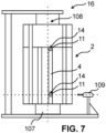
- the machining of the stator 2 according to the example of Figure 2 is performed with a machining station 16 supporting the stator 2 during the machining, as schematically illustrated in Figure 7 .
- Said machining of the stator 2 comprises, in a first phase, machining the second contact surfaces 11 of the stator 2 provided on the beams 4 so that the second contact surfaces 11 together define the circle with the second radius 12, as described above in relation to Figure 3 .
- the beams 4, as illustrated in Figures 2 and 7 for example, extend in the longitudinal direction at the outer perimeter of the stator 2.
- said machining of the second contact surfaces 11 may be performed by, for example, precisely positioning the stator 2 in a vertical position on a rotating stand or spindle 107 of the machining station 16, such that the axis of rotation of the spindle 107 corresponds to a center axis 108 to be defined by the second contact surfaces 11 after the machining. Then, for example by utilizing rotational movement of the stator 2 precisely positioned and attached to the spindle 107, a machining tool placed outside the stator 2 may be used for removing material from the beams 4 or, as in the case of the example of Figure 1 , the contact plates 19 provided on the beams 4, so as to obtain the second contact surfaces 11 having the second radius 12. In embodiments where the contact plates 19 are used, they may be provided on the beams 4 by welding before the machining of the second contact surfaces 11.
- a threaded hole 14 is prepared at an exactly predetermined position of each of the second contact surfaces 11. Said preparing of the threaded hole 14 may be performed through a single drilling step wherein the hole and the thread are provided simultaneously, or through separate steps of first preparing an unthreaded hole and then providing it with a thread.
- said exactly predetermined position may be obtained by, for example, placing a drilling tool 109 with a drilling head to a position in the machining station 16 precisely corresponding to the desired positions of the threaded holes 14 in the direction of the center axis 108, as schematically illustrated in the example of Figure 7 .
- Said placing of the drilling tool 109 may be performed based on, for example, the known position of the spindle 107 and of the stator 2 placed on the spindle 107.
- the stator 2 may be rotated in relation to the drilling head to obtain the correct angular position of each threaded hole 14.
- the machining station 15 used for the machining of the stator frame 5 may also be used for the machining of the stator 2, such that no separate machining station 16 is needed for machining the stator 2.
- the method of assembling the electric motor 1 according to the example of Figure 1 is continued by inserting the stator 2 into the stator frame 5 through the openings 7 to a position in which a tight contact is formed between the first contact surfaces 9 of the intermediate plates 6 and corresponding second contact surfaces 11 of the stator 2.
- said inserting may be performed by, for example, lowering the stator 2 in the vertical position towards the stator 5 frame from above, such that the openings 7 are positioned to open upwards for receiving the stator 2.
- Said tight contact is then formed as the first contact surfaces 9 defining the circle with the first radius 10 and the corresponding second contact surfaces 11 defining the circle with the second radius 12 are positioned to face towards each other, the first radius 10 being slightly larger than the second radius 12.
- the method may further comprise heating the stator frame 5 before said inserting the stator 2 into the stator frame 5, so as to form the tight contact by creating a shrink fit between the first contact surfaces 9 and the corresponding second contact surfaces 11.
- the inserting the stator 2 into the stator frame 5 may also comprise the step of guiding the guide pin 17 into the centering fork 18.
- the guide pin 17 and the centering fork 18 may be used for positioning the stator 2 in relation to the stator frame 5 to ensure the correct angular positioning of said parts around the center axis 8.
- said flange may be used for positioning the stator 2 in relation to the stator frame 5 in the axial direction of the stator 2.
- the assembly of the electric motor 1 is continued by providing the bolts 13 to extend through the drillings provided to the stator frame 5 and to threadedly engage the threaded holes 14 provided to the stator 2. More precisely, the bolts 13 may be inserted to the holes drilled into the stator frame 5 from the outside of the frame, such that their threaded ends engage the threads provided to the threaded holes 14, and the other ends of the bolts 13 that may be provided with the bolt head 103 engage the opening areas of the drilled holes of the stator frame 5. At this point, the bolts 13 may be tensioned to provide the intended level of compressive force to the stator-stator frame contact interface, locking the stator 2 and the stator frame 5 together to withstand both axial and torsional loads subjected towards them.
Landscapes
- Engineering & Computer Science (AREA)
- Power Engineering (AREA)
- Manufacturing & Machinery (AREA)
- Manufacture Of Motors, Generators (AREA)
- Motor Or Generator Frames (AREA)
- Iron Core Of Rotating Electric Machines (AREA)
Abstract
This invention relates to an electric motor (1) which comprises a stator (2) with an outer perimeter provided with beams (4) and a stator frame (5) surrounding the stator (2) and comprising at least two intermediate plates (6) having openings (7) for receiving the stator (2). For enabling simplified assembly of the electric motor (1), the intermediate plates (6) comprise first contact surfaces (9) forming a tight contact with corresponding second contact surfaces (11) provided on the beams (4). The electric motor (1) is provided with bolts (13) extending through the intermediate plates (6) between the outside of the stator frame (5) and the openings (7) at an exactly predetermined position of each of the first contact surfaces (9) and engaging threaded holes (14) provided to an exactly predetermined position of each of the second contact surfaces (11).
Description
- This invention relates to an electric motor and a method for assembling an electric motor.
- In the manufacture of industrial electric motors, the motor components are typically manufactured separately and assembled first into several separate sub-entities forming the structural base units of the motor. These structural base units include, for example, the stator and rotor assemblies, as well as the stator frame. These separate sub-entities are then assembled into the final motor unit during later steps of the manufacturing process. The final motor assembly is typically performed using both shrink fit connection and mechanical connector elements between the sub-entities, such that reception points for the mechanical connector elements need to be prepared and carefully positioned at corresponding connecting surfaces at each of the sub-entities to be assembled.
- A challenge related to electric motors is that even very small deviations in the dimensions or mutual locations of the components of the electric motor may have a significant impact on the properties and performance of the motor. Problems in the form of vibrations may occur, in case the components of the electric motor have not been rigidly attached to each other at exactly the correct mutual positions.
- An object of the present invention is to solve the above-mentioned drawbacks and to provide a solution for simplified electric motor assembly and robust connection between a stator and a stator frame. These objects are achieved with a method according to
independent claim 1 and an electric motor according toindependent claim 5. - By machining a stator frame such that it is drilled through intermediate plates at an exactly predetermined position of each of first contact surfaces of the intermediate plates, and by machining a stator by preparing a threaded hole at an exactly predetermined position of each of second contact surfaces provided on beams of the stator, and by then inserting the stator into the stator frame, the stator frame and the stator may be machined separately to conveniently provide a robust connection between the stator and the stator frame.
- Preferred embodiments of the invention are disclosed in the dependent claims.
- In the following the present invention will be described in closer detail by way of example and with reference to the attached drawings, in which
-
Figure 1 illustrates one embodiment of an electric motor as seen diagonally from above, -
Figure 2 illustrates a stator core of the electric motor ofFigure 1 as seen diagonally from above, -
Figure 3 illustrates a crosscut section of the electric motor ofFigure 1 as seen directly from the front, -
Figure 4 illustrates a partial view of the stator core ofFigure 2 , -
Figure 5 illustrates a detail of the electric motor ofFigure 1 as seen diagonally from above, -
Figure 6 illustrates a stator frame of the electric motor ofFigure 1 attached to a machining station as seen directly from the side, and -
Figure 7 illustrates the stator core ofFigure 2 attached to a machining station as seen directly from the side. -
Figure 1 illustrates one embodiment of anelectric motor 1, wherein a rotor included in the motor assembly has been faded out and is only presented with a dashed line, so as to more clearly illustrate the other structural units of the motor. As seen in this example, theelectric motor 1 comprises astator 2 operationally connecting to therotor 3 for providing torque to it, in other words such that in operation, a magnetic field is created in thestator 2 to generate torque to a shaft of the rotor and causing it to rotate. Therotor 3 in said example is arranged inside thestator 2 to be coaxial with it, and it may represent, for example, any rotor construction known from prior art. Theelectric motor 1 also comprises astator frame 5 surrounding thestator 2, wherein in the example ofFigure 1 thestator frame 5 comprises twointermediate plates 6 having coaxially aligned openings 7 for receiving thestator 2. Saidintermediate plates 6 are in the example arranged betweenframe end shields stator 2 and therotor 3. In other embodiments of theelectric motor 1, the number and positioning of theintermediate plates 6 may also deviate from the example ofFigure 1 , such that also a plurality ofintermediate plates 6 may be included in the construction. - To further illustrate the structure of the
stator 2,Figure 2 illustrates a stator core assembly of theelectric motor 1 ofFigure 1 as separated from the rest of the motor construction. As best seen in this example, the outer perimeter of thestator 2, which in this case corresponds to the circumference of the cylindricallyshaped stator 2, is provided withbeams 4 extending in a longitudinal direction of thestator 2.Said beams 4 may be used for, for example, binding together laminations forming the core of thestator 2 and to provide added rigidity to the stator construction, and their number as well as positioning at the outer perimeter of thestator 2 may deviate from the example ofFigure 2 in other embodiments of theelectric motor 1. - To further illustrate the structure of the
stator frame 5 and of the reciprocal arrangement of thestator 2 and the stator frame,Figure 3 illustrates a crosscut section of theelectric motor 1 ofFigure 1 in a direction perpendicular to the longitudinal direction of thestator 2. As best seen in this example, the at least twointermediate plates 6 of the stator frame comprise first contact surfaces 9 facing towards acenter axis 8, saidcenter axis 8 being located in the middle section of thestator frame 5 and oriented along the longitudinal direction of the frame, such that the first contact surfaces 9 together define a circle with afirst radius 10. In other words, said first contact surfaces 9 at each of theintermediate plates 6 are formed as curved surfaces following the curvature of a circle, the circle having thefirst radius 10 and thecenter axis 8, thecenter axis 8 being shared between the first contact surfaces 9 of adjacentintermediate plates 6. In the example ofFigure 3 , some of the first contact surfaces 9 are provided toprotrusions 20 extending towards the center of the openings 7 at each of the openings 7, in other words such that theprotrusions 20 extend from the perimeter of the openings 7 and the first contact surfaces 9 are provided to their surface facing towards the center of the openings 7. Favorably, at least one of the first contact surfaces 9 is arranged this way. - As best seen in the example of
Figure 3 , the first contact surfaces 9 form a tight contact with correspondingsecond contact surfaces 11 provided on thebeams 4. In more detail, saidsecond contact surfaces 11, which in the example ofFigure 3 are provided to the surfaces of thebeams 4 facing away from thestator 2 in a radial direction, define together a circle with asecond radius 12 which is slightly smaller than thefirst radius 10, thereby enabling said tight contact to be formed between the first 9 and the correspondingsecond contact surfaces 11. In some embodiments of theelectric motor 1, the first contact surfaces 9 may be connected to the correspondingsecond contact surfaces 11 through a shrink fit, wherein the contact between the first 9 and thesecond contact surfaces 11 may be formed in a condition wherein thestator frame 5, at least in the vicinity of the first contact surfaces 9, is heated to an elevated temperature. Thus, the shrink fit connection is formed as a result of cooling-associated shrinking of theintermediate plates 6 and of the circle defined by the first contact surfaces 9 to tightly surround thestator 2. - To further illustrate the arrangement of the
second contact surfaces 11 at thestator 2,Figure 4 illustrates a partial view of thestator 2 ofFigure 2 . As best seen in this figure, in thestator 2 according to the example ofFigures 2 and4 thesecond contact surfaces 11 are provided to contact plates 19 provided on thebeams 4. More precisely, the contact plates 19 are provided on the surfaces of thebeams 4 facing away from thestator 2 in the radial direction, such that thesecond contact surfaces 11 are formed on the outer surfaces of the contact plates 19 and are thereby elevated from the surface level of thebeams 4. With the arrangement as described, the shape and dimensions of thesecond contact surfaces 11 may be adjusted by only affecting the contact plates 19, without needing to affect thebeams 4. The contact plates 19 may comprise, for example, steel plates having a rigid structure so as to resist any deformations caused by, for example, forces subjected towards the stator-stator frame contact interface during use of theelectric motor 1. In other embodiments of theelectric motor 1, only one or some of thesecond contact surfaces 11 may be provided to the contact plates 19, or they may be completely omitted such that thesecond contact surfaces 11 are provided directly on thebeams 4. - In the example of
Figure 4 , some of thesecond contact surfaces 11 are provided with aflange 23 for inhibiting movement of thestator 2 through the openings 7 past a predetermined position. More precisely, each of thesecond contact surfaces 11 provided on contact plates 19 close to the rear end of thestator 2 are provided with theflanges 23 extending away from thestator 2 in the radial direction of thestator 2, such that when thestator 2 is moved through the openings 7 until said predetermined position, theflanges 23 come into contact with theintermediate plates 6. With the arrangement as described, theflanges 23 may be used as an assisting surface for correctly positioning thestator 2 in relation to thestator core 5 in the axial direction of thestator 2. - As best seen in the example of
Figure 3 , theelectric motor 1 is provided withbolts 13 extending through theintermediate plates 6 between the outside of thestator frame 5 and the openings 7. More precisely, theelectric motor 1 is provided with drilled holes extending through the outer surface of thestator frame 5 and theintermediate plates 6 with a substantially perpendicular orientation with respect to thecenter axis 8, and thebolts 13 are provided to said drilled holes. Thebolts 13 extend at an exactly predetermined position of each of the first contact surfaces 9, in other words such that they extend to the openings 7 at said exactly predetermined positions, and engage threadedholes 14 provided to an exactly predetermined position of each of thesecond contact surfaces 11. In other words, said threadedholes 14 are provided at positions exactly matching the positions of the corresponding drilled holes of thestator frame 5, such that a continuous, undisrupted pathway is created for thebolts 13 extending through thestator frame 5 to thestator 2. - Said drilled holes of the
stator frame 5 may be provided without a thread so that thebolts 13 threadedly connect only to the threadedholes 14 provided to thesecond contact surfaces 11. Eachbolt 13 may also be provided with abolt head 103 engaging the opening area of the corresponding drilled hole of thestator frame 5, such that thebolts 13 may be tensioned between thestator 2 and thestator frame 5. With the arrangement as described, thestator 2 may be tightened against thestator frame 5 at each pair of the first 9 and thesecond contact surfaces 11, such that forces subjected towards the stator-stator frame contact interface during use of theelectric motor 1 are carried by thebolts 13 as well as by friction between the first 9 and thesecond contact surfaces 11. Thereby, said arrangement may be used for providing support against forces affecting the stator-stator frame contact interface both in radial and tangential directions of thecenter axis 8, as opposed to an arrangement where, for example, non-tensioned connecting pins are used for preventing the axial movement of the stator in relation to the frame and the radial movement of the stator is prevented by a shrink fit connection. Consequently, vibrations of theelectric motor 1 during use, and particularly during the start-up and shut-down phases of the motor operation, may be effectively dampened. - In the example of
Figure 3 , theelectric motor 1 is provided with twobolts 13 extending through theintermediate plates 6 at each of the first contact surfaces 9 and engaging corresponding two threadedholes 14 provided to thesecond contact surfaces 11 at exactly predetermined positions. In other words, in said example twobolts 13 are arranged into corresponding two parallel drilled holes extending at each pair of the first 9 and thesecond contact surfaces 11 of the stator-stator frame contact interface and engage the corresponding two threadedholes 14 that together with the drilled holes create a continuous, undisrupted pathway for thebolts 13. The number of thebolts 13 may be based on, for example, the tensioning force required in each application or construction of theelectric motor 1 and may deviate from said example in other embodiments of theelectric motor 1. Preferably, at least twobolts 13 are provided to each of the first contact surfaces 9. The drilled holes of thestator frame 5 may also be provided with countersinks or groove-shapedimmersed sections 104 as illustrated in the example ofFigure 3 , so as to enable thebolts 13 to be entirely embedded within the outer perimeter of thestator frame 5. - With the arrangement of the stator-stator frame contact interface as described, in other words by arranging the
bolts 13 to extend between theintermediate plates 6 and thebeams 4 of the stator, distance between theintermediate plates 6 may be set independently of the length of thestator 2 in its axial direction. More precisely, in said arrangement the distance between the outermostintermediate plates 6 may also be set smaller than thestator length 2, as opposed to conventional motor constructions wherein a contact interface is formed between the intermediate plates and end rings of the stator. This, in turn, allows the same stator frame design to be used in connection with various stator constructions having different outer dimensions, eliminating the need to modify the stator frame construction for each use case of theelectric motor 1. In the example ofFigure 1 , for example, the twointermediate plates 6 are located at adistance 22 from each other that is smaller than the length of thestator 2. - In the example of
Figure 3 , each of theintermediate plates 6 comprise four first contact surfaces 9, and thebolts 13 at two of these first contact surfaces 9 extend in an angle 21 of 20 - 25 degrees, preferably approximately 22 degrees, to the horizontal direction from above into the threadedholes 14 of the second contact surfaces 11. In other words, said two first contact surfaces 9, which in said example are provided toprotrusions 20 having an extension similar to that of the correspondingbolts 13, are located at opposite sides of thecenter axis 8 such that thebolts 13 at these contact surfaces form an angle of approximately 22 degrees with the horizontal direction indicated with a dashed line inFigure 3 . In this context, the horizontal direction refers to the direction as perceived in the installed position of theelectric motor 1. In other embodiments of theelectric motor 1, the angle 21 may also be set to be smaller than illustrated in the example ofFigure 3 , and it may be set based on, for example, number of poles of the electric motor. - Simultaneously, in said example the two other first contact surfaces 9 are located directly above and below the
stator 2. With the arrangement as described, an optimal distribution of forces affecting the stator-stator frame contact interface may be achieved between the four points of contact between thestator 2 and thestator frame 5, and the vibrations of theelectric motor 1 during use, particularly during the start-up and shut-down phases of the motor operation, may be further dampened. The arrangement and number of the contact points between thestator 2 and thestator frame 5 may be based on, for example, the estimated maximum loading condition of theelectric motor 1 in each application, such that the number of the first contact surfaces 9 at each of theintermediate plates 6 is preferably at least four, and that thebolts 13 at two of these contact surfaces form an angle 21 of preferably 20 to 25 degrees to the horizontal direction. The first 9 and the second contact surfaces 11 may be oriented such in relation to thebolts 13 that thebolts 13 form an approximately right angle with the corresponding contact surfaces. -
Figure 5 illustrates a detail of the electric motor according to the example ofFigure 1 . In this example, thestator 2 further comprises aguide pin 17 extending radially outwards from thestator 2, and thestator frame 5 further comprises a centeringfork 18 opening in the direction of thecenter axis 8. With said arrangement, the centeringfork 18 may be used for receiving theguide pin 17 when thestator 2 is received in thestator frame 5 during the assembly phase of theelectric motor 1, so as to guide thestator 2 into its correct angular position in relation to thestator frame 5. In other words, theguide pin 17 and the centeringfork 18 in said example are reciprocally positioned such that said correct angular position of thestator 2 is obtained when theguide pin 17 is received into the centeringfork 18. In the example ofFigure 5 , wherein thestator 2 is presented in its installed final position within thestator frame 5, theguide pin 17 extends through a slit formed between the two limbs of the centeringfork 18. - The
electric motor 1 according to the example ofFigure 1 may be assembled by first separately machining thestator 2 and thestator frame 5. In the method of assembling theelectric motor 1, thestator frame 5 is machined with amachining station 15, saidmachining station 15 supporting thestator frame 5 during the machining as schematically illustrated inFigure 6 . The machining thestator frame 5 comprises, in a first phase, machining the first contact surfaces 9 of the at least twointermediate plates 6 facing towards thecenter axis 8 so that the first contact surfaces 9 together define the circle with thefirst radius 10 at each of theintermediate plates 6, as described above in relation toFigure 3 . In praxis, said machining of the first contact surfaces 9 may be performed by, for example, precisely positioning thestator frame 5 in a vertical position on a rotating stand orspindle 105 of themachining station 15, such that the axis of rotation of thespindle 105 corresponds to thecenter axis 8 to be defined by the first contact surfaces 9 after the machining. Then, for example by utilizing rotational movement of thestator frame 5 precisely positioned and attached to thespindle 105, a machining tool placed inside the openings 7 of theintermediate plates 6 may be used for removing material from theintermediate plates 6 so as to obtain the first contact surfaces 9 having thefirst radius 10 and thecenter axis 8. - In a second phase of the machining of the
stator frame 5, which may be implemented before or after the above described first phase, thestator frame 5 is drilled through the at least twointermediate plates 6 between the outside of thestator frame 5 and the openings 7 at an exactly predetermined position of each of the first contact surfaces 9. By utilizing themachining station 15, possibly by not moving the stator frame on the machining station between the first and second phase, said exactly predetermined position may be obtained by, for example, placing adrilling tool 106 with a drilling head to a position in themachining station 15 precisely corresponding to the desired position of the drilled holes in the direction of thecenter axis 8, as schematically illustrated in the example ofFigure 6 . InFigure 6 , the positions of theintermediate plates 6 are indicated with dashed lines. Said placing of thedrilling tool 106 may be performed based on, for example, the known position of thespindle 105 and of thestator frame 5 placed on thespindle 105. Then, thestator frame 5 may be rotated in relation to the drilling head to obtain the correct angular position of each hole to be drilled, in other words position along the circumference of the circle with thefirst radius 10. - The machining of the
stator 2 according to the example ofFigure 2 is performed with amachining station 16 supporting thestator 2 during the machining, as schematically illustrated inFigure 7 . Said machining of thestator 2 comprises, in a first phase, machining the second contact surfaces 11 of thestator 2 provided on thebeams 4 so that the second contact surfaces 11 together define the circle with thesecond radius 12, as described above in relation toFigure 3 . Thebeams 4, as illustrated inFigures 2 and7 for example, extend in the longitudinal direction at the outer perimeter of thestator 2. In praxis, said machining of the second contact surfaces 11 may be performed by, for example, precisely positioning thestator 2 in a vertical position on a rotating stand orspindle 107 of themachining station 16, such that the axis of rotation of thespindle 107 corresponds to acenter axis 108 to be defined by the second contact surfaces 11 after the machining. Then, for example by utilizing rotational movement of thestator 2 precisely positioned and attached to thespindle 107, a machining tool placed outside thestator 2 may be used for removing material from thebeams 4 or, as in the case of the example ofFigure 1 , the contact plates 19 provided on thebeams 4, so as to obtain the second contact surfaces 11 having thesecond radius 12. In embodiments where the contact plates 19 are used, they may be provided on thebeams 4 by welding before the machining of the second contact surfaces 11. - In a second phase of the machining of the
stator 2, which may be implemented before or after the above mentioned first phase, a threadedhole 14 is prepared at an exactly predetermined position of each of the second contact surfaces 11. Said preparing of the threadedhole 14 may be performed through a single drilling step wherein the hole and the thread are provided simultaneously, or through separate steps of first preparing an unthreaded hole and then providing it with a thread. By utilizing themachining station 16, possibly by not moving the stator on the machining station between the first and second phase, said exactly predetermined position may be obtained by, for example, placing adrilling tool 109 with a drilling head to a position in themachining station 16 precisely corresponding to the desired positions of the threadedholes 14 in the direction of thecenter axis 108, as schematically illustrated in the example ofFigure 7 . Said placing of thedrilling tool 109 may be performed based on, for example, the known position of thespindle 107 and of thestator 2 placed on thespindle 107. Then, thestator 2 may be rotated in relation to the drilling head to obtain the correct angular position of each threadedhole 14. In some variations of the method of assembling theelectric motor 1, themachining station 15 used for the machining of thestator frame 5 may also be used for the machining of thestator 2, such that noseparate machining station 16 is needed for machining thestator 2. - After the machining, the method of assembling the
electric motor 1 according to the example ofFigure 1 is continued by inserting thestator 2 into thestator frame 5 through the openings 7 to a position in which a tight contact is formed between the first contact surfaces 9 of theintermediate plates 6 and corresponding second contact surfaces 11 of thestator 2. In praxis, said inserting may be performed by, for example, lowering thestator 2 in the vertical position towards thestator 5 frame from above, such that the openings 7 are positioned to open upwards for receiving thestator 2. Said tight contact is then formed as the first contact surfaces 9 defining the circle with thefirst radius 10 and the corresponding second contact surfaces 11 defining the circle with thesecond radius 12 are positioned to face towards each other, thefirst radius 10 being slightly larger than thesecond radius 12. In some variations of the method, the method may further comprise heating thestator frame 5 before said inserting thestator 2 into thestator frame 5, so as to form the tight contact by creating a shrink fit between the first contact surfaces 9 and the corresponding second contact surfaces 11. - In the
electric motor 1 according to the examples 1 to 7, wherein thestator 2 is provided with theguide pin 17 and thestator frame 5 is provided with the centeringfork 18, the inserting thestator 2 into thestator frame 5 may also comprise the step of guiding theguide pin 17 into the centeringfork 18. With said arrangement, theguide pin 17 and the centeringfork 18 may be used for positioning thestator 2 in relation to thestator frame 5 to ensure the correct angular positioning of said parts around thecenter axis 8. Similarly, in embodiments of theelectric motor 1 where at least one of the second contact surfaces 11 is provided with theflange 23, as described above in relation toFigure 4 , said flange may be used for positioning thestator 2 in relation to thestator frame 5 in the axial direction of thestator 2. - When the
stator 2 and thestator frame 5 have been positioned to their correct reciprocal positions, the assembly of theelectric motor 1 is continued by providing thebolts 13 to extend through the drillings provided to thestator frame 5 and to threadedly engage the threadedholes 14 provided to thestator 2. More precisely, thebolts 13 may be inserted to the holes drilled into thestator frame 5 from the outside of the frame, such that their threaded ends engage the threads provided to the threadedholes 14, and the other ends of thebolts 13 that may be provided with thebolt head 103 engage the opening areas of the drilled holes of thestator frame 5. At this point, thebolts 13 may be tensioned to provide the intended level of compressive force to the stator-stator frame contact interface, locking thestator 2 and thestator frame 5 together to withstand both axial and torsional loads subjected towards them. - It is to be understood that the above description and the accompanying figures are only intended to illustrate the present invention. It will be obvious to a person skilled in the art that the invention can be varied and modified without departing from the scope of the invention.
Claims (12)
- A method for assembling an electric motor (1), characterized in that the method comprises:
machining a stator frame (5) with at least two intermediate plates (6) having openings (7) with a machining station (15) supporting the stator frame (5) during the machining, said machining the stator frame (5) comprising:in a first phase, machining first contact surfaces (9) of the at least two intermediate plates (6) facing towards a center axis (8), said first contact surfaces (9) together defining a circle with a first radius (10) at each intermediate plate (6), andin a second phase, before or after the first phase, drilling the stator frame (5) through the at least two intermediate plates (6) between the outside of the stator frame (5) and the openings (7) at an exactly predetermined position of each of the first contact surfaces (9),machining a stator (2) with a machining station (16) supporting the stator (2) during the machining, said machining the stator (2) comprising:in a first phase, machining second contact surfaces (11) of the stator (2) which are provided on beams (4) extending in a longitudinal direction at an outer perimeter of the stator (2), so that the second contact surfaces (11) together define a circle with a second radius (12), andin a second phase, after or before said first phase, preparing a threaded hole (14) at an exactly predetermined position of each of the second contact surfaces (11),inserting the stator (2) into the stator frame (5) through the openings (7), to a position in which a tight contact is formed between the first contact surfaces (9) of the at least two intermediate plates (6) and corresponding second contact surfaces (11) of the stator (2), andproviding bolts (13) to extend through the drillings provided to the stator frame (5) and to threadedly engage the threaded holes (14) provided to the stator (2). - The method according to claim 1, characterized in that the method further comprises:
heating the stator frame (5) before the inserting the stator (2) into the stator frame (5) to form said tight contact by creating a shrink fit between the first contact surfaces (9) of the at least two intermediate plates (6) and the corresponding second contact surfaces (11) of the stator (2). - The method according to claim 1 or 2, characterized in that the inserting the stator (2) into the stator frame (5) comprises guiding a guide pin (17) extending radially outwards from the stator (2) into a centering fork (18) provided to the stator frame (5) and opening in the direction of the center axis (8).
- The method according to any one of the claims 1 to 3, characterized in that the method further comprises:
welding contact plates (19) on the beams (4) for providing the second contact surfaces (11) before the machining the second contact surfaces (11). - An electric motor (1), characterized in that the electric motor (1) comprises:a stator (2) with an outer perimeter being provided with beams (4) extending in a longitudinal direction of the stator (2), anda stator frame (5) surrounding the stator (2), the stator frame (5) comprising at least two intermediate plates (6) having openings (7) for receiving the stator (2), whereinthe at least two intermediate plates (6) comprise first contact surfaces (9) facing towards a center axis (8), the first contact surfaces (9) together defining a circle with a first radius (10) at each intermediate plate (6) and forming a tight contact with corresponding second contact surfaces (11) provided on the beams (4), the second contact surfaces (11) together defining a circle with a second radius (12), andthe electric motor (1) is provided with bolts (13) extending through the at least two intermediate plates (6) between the outside of the stator frame (5) and the openings (7) at an exactly predetermined position of each of the first contact surfaces (9) and engaging threaded holes (14) provided to an exactly predetermined position of each of the second contact surfaces (11).
- The electric motor (1) according to claim 5, characterized in that at least one of the first contact surfaces (9) is provided to a protrusion (20) extending towards the center of the openings (7) at each of the openings (7), and
at least one of the second contact surfaces (11) is provided to a contact plate (19) provided on the beams (4). - The electric motor (1) according to claim 5 or 6, characterized in that the first contact surfaces (9) are connected to the corresponding second contact surfaces (11) through a shrink fit.
- The electric motor (1) according to any one of the claims 5 to 7, characterized in that each of the at least two intermediate plates (6) comprise at least four first contact surfaces (9), and
bolts (13) at two of the at least four first contact surfaces (9) extend in an angle (21) of 20 to 25 degrees to the horizontal direction from above into the threaded holes (14) of the second contact surfaces (11). - The electric motor (1) according to any one of the claims 5 to 8, characterized in that the electric motor (1) is provided with at least two bolts (13) extending through the at least two intermediate plates (6) at each of the first contact surfaces (9) and engaging corresponding at least two threaded holes (14) provided to exactly predetermined positions of each of the second contact surfaces (11).
- The electric motor (1) according to any one of the claims 5 to 9, characterized in that the stator (2) further comprises a guide pin (17) extending radially outwards from the stator (2), and
the stator frame (5) further comprises a centering fork (18) opening in the direction of the center axis (8) for receiving the guide pin (17) when the stator (2) is received in the stator frame (5). - The electric motor (1) according to any one of the claims 5 to 10, characterized in that the at least two intermediate plates (6) are located at a distance (22) from each other that is smaller than the length of the stator (2).
- The electric motor (1) according to any one of the claims 5 to 11, characterized in that at least one of the second contact surfaces (11) is provided with a flange (23) protruding outwards from the second contact surface for inhibiting movement of the stator (2) through the openings (7) past a predetermined position.
Priority Applications (3)
| Application Number | Priority Date | Filing Date | Title |
|---|---|---|---|
| EP23187522.0A EP4498573A1 (en) | 2023-07-25 | 2023-07-25 | An electric motor and a method for assembling an electric motor |
| US18/773,738 US20250038588A1 (en) | 2023-07-25 | 2024-07-16 | Electric Motor and A Method for Assembling an Electric Motor |
| CN202410992068.6A CN119543491A (en) | 2023-07-25 | 2024-07-23 | Electric machine and method for assembling an electric machine |
Applications Claiming Priority (1)
| Application Number | Priority Date | Filing Date | Title |
|---|---|---|---|
| EP23187522.0A EP4498573A1 (en) | 2023-07-25 | 2023-07-25 | An electric motor and a method for assembling an electric motor |
Publications (1)
| Publication Number | Publication Date |
|---|---|
| EP4498573A1 true EP4498573A1 (en) | 2025-01-29 |
Family
ID=87474218
Family Applications (1)
| Application Number | Title | Priority Date | Filing Date |
|---|---|---|---|
| EP23187522.0A Pending EP4498573A1 (en) | 2023-07-25 | 2023-07-25 | An electric motor and a method for assembling an electric motor |
Country Status (3)
| Country | Link |
|---|---|
| US (1) | US20250038588A1 (en) |
| EP (1) | EP4498573A1 (en) |
| CN (1) | CN119543491A (en) |
Citations (6)
| Publication number | Priority date | Publication date | Assignee | Title |
|---|---|---|---|---|
| US20070215773A1 (en) * | 2006-03-02 | 2007-09-20 | Kerr Jack R Jr | Mounting bracket assembly |
| US20110121680A1 (en) * | 2009-11-20 | 2011-05-26 | General Electric Company | Stator core suspension and related spring bar |
| EP2256904B1 (en) * | 2009-05-26 | 2013-05-15 | Converteam Technology Ltd | Supporting structure of a rotating electrical machine stator and rotating electrical machine stator with said supporting structure |
| US20180175697A1 (en) * | 2014-03-26 | 2018-06-21 | Abb Schweiz Ag | Electric machine |
| US20200343778A1 (en) * | 2018-01-11 | 2020-10-29 | Abb Schweiz Ag | Electric machine |
| EP4002647A1 (en) * | 2020-11-12 | 2022-05-25 | Siemens Aktiengesellschaft | Electrical machine and wind power plant |
-
2023
- 2023-07-25 EP EP23187522.0A patent/EP4498573A1/en active Pending
-
2024
- 2024-07-16 US US18/773,738 patent/US20250038588A1/en active Pending
- 2024-07-23 CN CN202410992068.6A patent/CN119543491A/en active Pending
Patent Citations (6)
| Publication number | Priority date | Publication date | Assignee | Title |
|---|---|---|---|---|
| US20070215773A1 (en) * | 2006-03-02 | 2007-09-20 | Kerr Jack R Jr | Mounting bracket assembly |
| EP2256904B1 (en) * | 2009-05-26 | 2013-05-15 | Converteam Technology Ltd | Supporting structure of a rotating electrical machine stator and rotating electrical machine stator with said supporting structure |
| US20110121680A1 (en) * | 2009-11-20 | 2011-05-26 | General Electric Company | Stator core suspension and related spring bar |
| US20180175697A1 (en) * | 2014-03-26 | 2018-06-21 | Abb Schweiz Ag | Electric machine |
| US20200343778A1 (en) * | 2018-01-11 | 2020-10-29 | Abb Schweiz Ag | Electric machine |
| EP4002647A1 (en) * | 2020-11-12 | 2022-05-25 | Siemens Aktiengesellschaft | Electrical machine and wind power plant |
Also Published As
| Publication number | Publication date |
|---|---|
| CN119543491A (en) | 2025-02-28 |
| US20250038588A1 (en) | 2025-01-30 |
Similar Documents
| Publication | Publication Date | Title |
|---|---|---|
| JP5331049B2 (en) | Rotor insertion device and insertion method for rotating electrical machine | |
| US8138654B2 (en) | System and method for generator stator mounting | |
| CN102232146B (en) | Wind turbine generator and maintenance method thereof | |
| US4110652A (en) | Mounting assembly for laminated rotor rim of dynamoelectric generator rotatable about inclined shaft | |
| CN101978581B (en) | How to Repair Your Generator | |
| DE102010016887A1 (en) | Device for mounting the stator of a generator | |
| JPH0219694B2 (en) | ||
| US8829760B2 (en) | Dynamoelectric machine support system | |
| US20180278106A1 (en) | Rotor for induction motor and induction motor | |
| US7451538B2 (en) | Method for fabricating rotor assembly | |
| EP4498573A1 (en) | An electric motor and a method for assembling an electric motor | |
| EP2884628A2 (en) | Spring assemblies for supporting a stator core in a stator frame | |
| WO2015144677A2 (en) | An electric machine | |
| US6710497B2 (en) | Apparatus and method for a field winding assembly mountable on a rotor in a synchronous machine | |
| JPH0637891B2 (en) | Rotor centering device and journal bearing support method | |
| EP3738191B1 (en) | An electric machine | |
| US20230034019A1 (en) | Assembly method and fixing device for electric motor | |
| EP2884627A2 (en) | Repair method of spring assemblies in a stator core | |
| US20060101643A1 (en) | Methods of installing centerline supported carriers for steam turbines | |
| JP6705789B2 (en) | Stator assembly method | |
| CN117526597A (en) | Rotor components, motor rotors, electric machines and wind turbines | |
| KR102716100B1 (en) | Apparatus and method for manufacturing core pack of rotor | |
| US1749728A (en) | Split frame for dynamo-electric machines and method of making the same | |
| JP2019122212A (en) | Insulator assembling method |
Legal Events
| Date | Code | Title | Description |
|---|---|---|---|
| PUAI | Public reference made under article 153(3) epc to a published international application that has entered the european phase |
Free format text: ORIGINAL CODE: 0009012 |
|
| STAA | Information on the status of an ep patent application or granted ep patent |
Free format text: STATUS: THE APPLICATION HAS BEEN PUBLISHED |
|
| AK | Designated contracting states |
Kind code of ref document: A1 Designated state(s): AL AT BE BG CH CY CZ DE DK EE ES FI FR GB GR HR HU IE IS IT LI LT LU LV MC ME MK MT NL NO PL PT RO RS SE SI SK SM TR |
|
| STAA | Information on the status of an ep patent application or granted ep patent |
Free format text: STATUS: REQUEST FOR EXAMINATION WAS MADE |
|
| 17P | Request for examination filed |
Effective date: 20250728 |