EP4498569A1 - Backup power supply - Google Patents
Backup power supply Download PDFInfo
- Publication number
- EP4498569A1 EP4498569A1 EP23774213.5A EP23774213A EP4498569A1 EP 4498569 A1 EP4498569 A1 EP 4498569A1 EP 23774213 A EP23774213 A EP 23774213A EP 4498569 A1 EP4498569 A1 EP 4498569A1
- Authority
- EP
- European Patent Office
- Prior art keywords
- power supply
- mpu
- circuit
- voltage
- external
- Prior art date
- Legal status (The legal status is an assumption and is not a legal conclusion. Google has not performed a legal analysis and makes no representation as to the accuracy of the status listed.)
- Pending
Links
Images

Classifications
-
- H—ELECTRICITY
- H02—GENERATION; CONVERSION OR DISTRIBUTION OF ELECTRIC POWER
- H02J—CIRCUIT ARRANGEMENTS OR SYSTEMS FOR SUPPLYING OR DISTRIBUTING ELECTRIC POWER; SYSTEMS FOR STORING ELECTRIC ENERGY
- H02J9/00—Circuit arrangements for emergency or stand-by power supply, e.g. for emergency lighting
- H02J9/04—Circuit arrangements for emergency or stand-by power supply, e.g. for emergency lighting in which the distribution system is disconnected from the normal source and connected to a standby source
- H02J9/06—Circuit arrangements for emergency or stand-by power supply, e.g. for emergency lighting in which the distribution system is disconnected from the normal source and connected to a standby source with automatic change-over, e.g. UPS systems
- H02J9/061—Circuit arrangements for emergency or stand-by power supply, e.g. for emergency lighting in which the distribution system is disconnected from the normal source and connected to a standby source with automatic change-over, e.g. UPS systems for DC powered loads
-
- Y—GENERAL TAGGING OF NEW TECHNOLOGICAL DEVELOPMENTS; GENERAL TAGGING OF CROSS-SECTIONAL TECHNOLOGIES SPANNING OVER SEVERAL SECTIONS OF THE IPC; TECHNICAL SUBJECTS COVERED BY FORMER USPC CROSS-REFERENCE ART COLLECTIONS [XRACs] AND DIGESTS
- Y02—TECHNOLOGIES OR APPLICATIONS FOR MITIGATION OR ADAPTATION AGAINST CLIMATE CHANGE
- Y02E—REDUCTION OF GREENHOUSE GAS [GHG] EMISSIONS, RELATED TO ENERGY GENERATION, TRANSMISSION OR DISTRIBUTION
- Y02E60/00—Enabling technologies; Technologies with a potential or indirect contribution to GHG emissions mitigation
- Y02E60/10—Energy storage using batteries
Definitions
- the present disclosure relates to a backup power supply including a battery module, and particularly to a backup power supply including a micro-processing unit (MPU) configured to manage the state of the battery module.
- MPU micro-processing unit
- a micro-processing unit In a power supply device including a battery module, a micro-processing unit (MPU) is included to prevent over-charge and over-discharge of the battery module and to determine, for example, the degree of degradation of the battery module.
- PTL 1 In the description of the present disclosure, the MPU includes a micro controller unit (MCU).
- a backup power supply includes a battery module configured to supply power to a connected external load to keep the external load in an operating state in the event of a power failure.
- the backup power supply is required to be healthy to provide a stable supply voltage from the battery module to the external load in the event of a power failure.
- the backup power supply includes a MPU configured to monitor the state of the battery module to manage the battery module and keep the battery module healthy.
- the MPU is maintained in an operating state by the power supply voltage supplied from the battery module. This configuration causes the MPU to discharge the battery module, reducing remaining capacity of the battery module. Since the backup power supply is always connected to an external load, the power consumption of the battery module is reduced by supplying the power supply voltage from the main power supply provided in the external load to the MPU.
- the backup power supply supplies power to an external load only in the event of a power failure.
- power is rarely supplied to the external load in the event of a power failure.
- the consumption of the power from the battery module for the MPU can be reduced.
- the backup power supply configured to supply a power supply voltage to the MPU from both the battery module and the main power supply includes a power supply circuit, such as a DC-to-DC converter configured to adjust the voltage of the main power supply and the voltage of the battery module for conversion into the power supply voltage of the MPU.
- a power supply circuit such as a DC-to-DC converter configured to adjust the voltage of the main power supply and the voltage of the battery module for conversion into the power supply voltage of the MPU.
- the power consumption of the backup power supply itself is required to be small out of the power of the battery module to allow the external load to be powered even at the time of a long power failure.
- a backup power supply includes: a battery module including a plurality of battery cells; a micro-processing unit (MPU) connected to the battery module; a first power supply circuit configured to supply a power supply voltage from the battery module to the MPU, the power supply voltage powering the MPU; a switching element configured to supply the power supply voltage from the first power supply circuit to the MPU; a second power supply circuit configured to convert external power into the power supply voltage to supply the power supply voltage to the MPU, the external power being supplied from a main power supply of an external load connected; and a power supply switching circuit configured to detect an input of the external power from the main power supply of the external load to the backup power supply so as to control the switching element.
- MPU micro-processing unit
- the power supply switching circuit is configured to, in an input period during which the external power is supplied from the external load, turn off the switching element to stop supplying the power supply voltage from the first power supply circuit to the MPU and to supply the power supply voltage from the second power supply circuit to the MPU.
- the power supply switching circuit is configured to, in a non-input period during which the external power is not supplied from the external load, turn on the switching element to supply the power supply voltage from the first power supply circuit to the MPU.
- the backup power supply described above efficiently supplies the power supply voltage to the MPU from both the battery module and the main power supply while reducing the power consumption of the battery module.
- FIG. 1 is a circuit diagram of backup power supply 90 according to a comparative example, in which the voltage is adjusted and supplied to MPU 92 from battery module 91 and main power supply 99.
- Backup power supply 90 includes a first power supply circuit in analog front end (AFE) 93. The first power supply circuit is configured to adjust the voltage of battery module 91 and supple the adjusted voltage to MPU 92.
- Backup power supply 90 further includes second power supply circuit 95 configured to adjust the voltage of the external power input from main power supply 99 and supply the adjusted voltage to MPU 92.
- first power supply circuit 94 and second power supply circuit 95 are connected to power supply terminal 92a of MPU 92 via diodes 96.
- backup power supply 90 illustrated in FIG. 1 in order to supply power supply voltage to MPU 92 from second power supply circuit 95 while the power supply voltage is supplied to MPU 92 from both first power supply circuit 94 and second power supply circuit 95, two diodes 96 connected in series to each other to an output side of first power supply circuit 94, and second power supply circuit 95 supplies the power supply voltage to MPU 92 via single diode 96. Since a voltage drop across a diode ranges from about 0.6 V to 0.7 V, a voltage drop of two diodes 96 connected in series to each other is high ranging from 1.2 V to 1.4 V.
- backup power supply 90 in the period during which external power is not supplied, power supply voltage is supplied from the first power supply circuit to the MPU.
- the power supply voltage is supplied from the second power supply circuit to the MPU while the power supply voltage is not supplied from the first power supply circuit to the MPU.
- the diodes switch between the power supply circuits, such that the power supply voltage is supplied from the second power supply circuit to the MPU.
- This circuit configuration may be a simple circuit configuration in which the supply of the power supply circuit is selected by the number of diodes. However, diodes wastefully consume power due to a large voltage drop of the diodes. In the period during which the power supply voltage is supplied from the second power supply circuit to the MPU, the diodes wastefully consume power.
- a backup power supply includes: a battery module including a plurality of battery cells; a micro-processing unit (MPU) connected to the battery module; a first power supply circuit configured to supply a power supply voltage from the battery module to the MPU, the power supply voltage powering the MPU; a switching element configured to supply the power supply voltage from the first power supply circuit to the MPU; a second power supply circuit configured to convert external power into the power supply voltage to supply the power supply voltage to the MPU, the external power being supplied from a main power supply of an external load connected; and a power supply switching circuit configured to detect an input of the external power from the main power supply of the external load to the backup power supply so as to control the switching element.
- MPU micro-processing unit
- the power supply switching circuit is configured to, in an input period during which the external power is supplied from the external load, turn off the switching element to stop supplying the power supply voltage from the first power supply circuit to the MPU and to supply the power supply voltage from the second power supply circuit to the MPU.
- the power supply switching circuit is configured to, in a non-input period during which the external power is not supplied from the external load, turn on the switching element to supply the power supply voltage from the first power supply circuit to the MPU.
- the power supply switching circuit causes the second power supply circuit to adjust the voltage of the external power to supply the power supply voltage to the MPU, turns off the switching element that supplies the power supply voltage from the first power supply circuit to the MPU so as to stop supplying the power supply voltage from the first power supply circuit to the MPU.
- the power supply switching circuit turns on the switching element to supply the power supply volage from the first power supply circuit to the MPU and maintain the MPU in an operating state.
- the second power supply circuit adjusts the voltage of the external power supplied from the external load and supplies the voltage to the MPU, so that the power consumption of the battery module during this period is reduced.
- the first power supply circuit adjusts the voltage of the output of the battery module and supplies the voltage to the MPU to always maintain the MPU to operate.
- the backup power supply described above switches the supply of the power supply voltage to the MPU. Therefore, the power supply voltage is efficiently supplied to the MPU from one of the external load and the battery module without supplying the power supply voltage to the MPU via diodes from the first power supply circuit and the second power supply circuit as in conventional circuitry. Furthermore, in the input period during which the external power is supplied from the external load, the power supply voltage may not necessarily be supplied from the battery module to the MPU. Therefore, the MPU is maintained to operate while significantly reducing the power consumption of the battery module. In particular, in the backup power supply, most of the time is the input period during which the external power is supplied from the external load. Therefore, the time period during which the power supply voltage is supplied from the battery module to the MPU is extremely short, and the power consumption of the battery module is significantly reduced while always maintaining the MPU to operate.
- the second power supply circuit may be configured to start outputting the power supply voltage to the MPU in response to an activation signal causing the power supply switching circuit to turn off the switching element.
- the second power supply circuit starts outputting the power supply voltage to the MPU in response to an activation signal to turn off the switching element that controls a supply of the power supply voltage from the first power supply circuit to the MPU. Accordingly, at the time of switching between the first power supply circuit and the second power supply circuit, the power supply voltage is prevented from being supplied to the MPU from both of the first power supply circuit and the second power supply circuit simultaneously, and is supplied to the MPU from one of the power supply circuits. It is not possible to make the output voltage of the first power supply circuit completely equal to the output voltage of the second power supply circuit.
- backup power supply 90 provides a problem that, a voltage higher than the output is supplied to the output side of the power supply circuit that outputs a lower volage.
- the second power supply circuit starts output in response to an activation signal so as to cause the switching element to stop the output of the first power supply circuit. Accordingly, the first power supply circuit and the second power supply circuit do not supply the power supply voltage to the MPU simultaneously. This configuration eliminates the problem that a voltage higher than the output is input to the first power supply circuit and the second power supply circuit.
- the power supply switching circuit may include a trigger circuit configured to output an activation signal when a voltage of the external power exceeds a threshold.
- the power supply switching circuit may be configured to turn off the switching element in response to the activation signal output from the trigger circuit to cause the second power supply circuit to start supplying the power supply voltage to the MPU.
- the power supply voltage starts to be supplied from the second power supply circuit to the MPU after the external power reaches a predetermined voltage. Accordingly, it is possible to supply a predetermined power supply volage from the second power supply circuit to the MPU, and to simultaneously cause the switching element to stop supplying power from the first power supply circuit to the MPU.
- the second power supply circuit may include: a DC-to-DC converter configured to operate upon receiving the external power from the main power supply of the external load; and a control terminal configured to supply an output of the DC-to-DC converter to the MPU in response to an input of the activation signal.
- the DC-to-DC converter may be configured to start outputting the power supply voltage to the MPU in response to the activation signal input to the control terminal.
- the switching element may be configured to be turned off in response to the activation signal.
- the DC-to-DC converter operates in the period during which the external power is supplied to gradually increase the output voltage. After that, an activation signal is input to the control terminal, and the second power supply circuit supplies the power supply volage to the MPU. Accordingly, even while external power with a time delay in voltage increase is input, the DC-to-DC converter of the second power supply circuit supplies a predetermined power supply voltage to the MPU.
- the power supply switching circuit may further include a trigger circuit configured to output a stop signal when a voltage of the external power becomes equal to or less than a threshold.
- the switching element may be configured to be switched from being turned off to being turned on in response to the stop signal so as to cause the first power supply circuit to supply the power supply voltage to the MPU.
- the first power supply circuit outputs the power supply voltage to the MPU while the output voltage of the second power supply circuit has decreased to a predetermined voltage. Accordingly, it is possible to prevent both of the power supply circuits from supplying power supply volage with a substantially-equal voltage difference to the MPU.
- the backup power supply according to another aspect of the present disclosure may further include a capacitor connected to an output side of the second power supply circuit.
- the capacitor is configured to reduce a change in the power supply voltage supplied from the second power supply circuit to the MPU.
- the power supply voltage is supplied to the MPU stably while the capacitor reduces a change in the power supply voltage to the MPU.
- the capacitor has a capacitance of 0.45 ⁇ F or more.
- the power supply switching circuit operates with the external power as the power supply volage.
- the power supply switching circuit is powered by the external power. Accordingly, it is possible to switch the power supply volage of the MPU between the battery module and the external power while preventing the power supply switching circuit from consuming the power of the battery module.
- the power supply voltage supplied from each of the first power supply circuit and the second power supply circuit to the MPU may be 5 V.
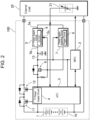
- Backup power supply 100 illustrated in FIG. 2 includes: battery module 10 including battery cells 1; analog front end (AFE) 3 and micro-processing unit (MPU) 2 that are connected to battery module 10; first power supply circuit 4 configured to supply a power supply voltage from battery module 10 to MPU 2; switching element 6 configured to supply power supply voltage from first power supply circuit 4 to MPU 2, second power supply circuit 5 configured to convert external power supplied from externally-connected external load 20 into the power supply voltage of MPU 2 and supply the power supply voltage to MPU 2; and power supply switching circuit 7 configured to detect an input of external power from main power supply 21 of external load 20 so as to control switching element 6.
- AFE analog front end
- MPU micro-processing unit
- power supply switching circuit 7 In an input period during which external power is supplied from external load 20, power supply switching circuit 7 is configured to turn off switching element 6 to stop supplying the power supply voltage from first power supply circuit 4 to MPU 2, and to supply power supply voltage from the second power supply circuit 5 to MPU 2. In a non-input period during which no external power is supplied from external load 20, power supply switching circuit 7 is configured to turn on switching element 6 so as to supply power supply voltage from first power supply circuit 4 to MPU 2. Specifically, at the time when external load 20 starts supplying external power, power supply switching circuit 7 switches switching element 6 from being turned on to being turned off to stop supplying the power supply voltage from first power supply circuit 4 to MPU 2, and to supply the power supply voltage from second power supply circuit 5 to MPU 2. Moreover, at the time when external load 20 stops supplying the external power, power supply switching circuit 7 switches switching element 6 from being turned off to being turned on so as to supply the power supply voltage from first power supply circuit 4 to MPU 2.
- Battery module 10 includes battery cells 1 connected in series or parallel to one another.
- Backup power supply 100 is configured to be connected to external load 20, such as a server.
- Backup power supply 100 is configured to supply power to external load 20 and maintain external load 20 to operate when power is not supplied to external load 20 from main power supply 21 in the event of a power failure.
- the time period during which backup power supply 100 maintains external load 20, such as a server, to operate in the event of a power failure is longer than a time period to start an engine generator or a time period to allow the server to successfully perform termination processing.
- Battery module 10 adjusts output voltage according to the number of battery cells 1 connected to direct-current, and adjusts output current and overall charge and discharge capacity according to the number of battery cells 1 connected in parallel to one another.
- Battery module 10 may have a capacity continuously supplying power supply voltage to external load 20 for several minutes.
- Lithium-ion rechargeable batteries may be used for battery cells 1. While lithium-ion rechargeable batteries have large charge and discharge capacities, the present disclosure does not specify battery cell 1. Any other rechargeable batteries, such as solid-state batteries, can also be used.
- MPU 2 is an integrated circuit that includes a microprocessor that digitally processes and monitors battery information, such as a voltage, a current, and a temperature of battery module 10.
- MPU 2 is configured to detect, e.g., a remaining capacity and degree of degradation of battery module 10, and control charging and discharging of battery module 10 to maintain battery module 10 in health.
- AFE 3 is configured to detect an analog signal corresponding to the voltage, current, or temperature of battery module 10, and controls turning on and off of charge switching element 11 and discharge switching element 12 that control charging and discharging of battery module 10.
- AFE 3 converts the detected analog signal into a digital signal, and transmits the digital signal to MPU 2.
- MPU 2 processes the digital signal input from AFE 3 and outputs the processed result to AFE 3, and further outputs information, such as remaining capacity and the degree of degradation to external load 20.
- MPU 2 is always maintained to operate regardless of the state of external load 20 to monitor battery module 10.
- the power supply voltage is supplied to MPU 2 from either battery module 10 or main power supply 21 of external load 20 for powering MPU 2 so as to always maintain MPU 2 to operate.
- First power supply circuit 4 adjusts the output voltage of battery module 10 to the power supply voltage of MPU 2, and supplies the power supply voltage to MPU 2.
- First power supply circuit 4 converts the voltage of battery module 10 into the power supply voltage of MPU 2 and outputs the power supply voltage in the input period and the non-input period of the external power.
- First power supply circuit 4 supplies the power supply voltage to MPU 2 via switching element 6. Switching element 6 is turned on in the non-input period during which external power is not supplied, so that the power supply voltage is supplied from first power supply circuit 4 to MPU 2.
- Backup power supply 100 in FIG. 2 includes first power supply circuit 4 of AFE 3 of the integrated circuit. However, first power supply circuit 4 may not necessarily be included in AFE 3, but may be disposed as a circuit external to AFE 3. First power supply circuit 4 always outputs the output voltage of battery module 10 as the power supply voltage of MPU 2.
- Second power supply circuit 5 converts the voltage of the external power supplied from main power supply 21 of external load 20 into the power supply voltage of MPU 2 and outputs the power supply voltage.
- Second power supply circuit 5 includes power supply terminal 5a configured to receive the external power, output terminal 5b configured to supply power supply voltage to MPU 2, and control terminal 5c configured to control the time period during which power supply voltage is output from power supply terminal 5a to MPU 2.
- Second power supply circuit 5 includes DC-to-DC converter 9 configured to convert the voltage of external power into the power supply voltage of MPU 2.
- DC-to-DC converter 9 is powered by the external power input from power supply terminal 5a to operate. The output of DC-to-DC converter 9 is controlled by an activation signal input to control terminal 5c.
- One of the "High” and “Low” levels of an activation signal serves as an activation signal that supplies power supply voltage to MPU 2
- the other one of the “High” and “Low” levels of the activation signal serves as a non-activation signal that switches the supply state into a state where no power supply voltage is supplied to MPU 2.
- Backup power supply 100 illustrated in FIG. 2 includes capacitor 13 connected to on the output side of second power supply circuit 5.
- Capacitor 13 reduces sudden changes in power supply voltage supplied from second power supply circuit 5 to MPU 2.
- the backup power supply with the configuration above stably supplies power supply voltage to MPU 2 by reducing changes in the power supply voltage supplied to MPU 2 using capacitor 13 at the time of switching between first power supply circuit 4 and second power supply circuit 5.
- Capacitor 13 has a capacitance of, e.g., 0.45 ⁇ F or more, which ideally reduces changes in voltage at the time of switching between the first power supply circuit and the second power supply circuit, leading to a stable supply of the power supply voltage to the MPU 2.
- Switching element 6 is a semiconductor switching element.
- Switching element 6 may employ a field effect transistor (FET), but may employ a bipolar transistor. The FET is turned on and off in response to a gate input voltage.
- Switching element 6 supplies the power supply voltage from second power supply circuit 5 to MPU 2 while switching element 6 is turned on, and stops supplying the power supply voltage from second power supply circuit 5 to MPU 2 while switching element 6 is turned off.
- FET field effect transistor
- Power supply switching circuit 7 is configured to control switching element 6 and second power supply circuit 5 by determining an input period during which external power is supplied from main power supply 21 of external load 20 and a non-input period during which no external power is supplied. Power supply switching circuit 7 performs the control such that, in the input period, the power supply voltage is supplied to MPU 2 only from second power supply circuit 5 out of first power supply circuit 4 and second power supply circuit 5. Power supply switching circuit 7 further performs the control such that, in the non-input period, the power supply voltage is supplied to MPU 2 only from first power supply circuit 4 out of first power supply circuit 4 and second power supply circuit 5.
- Power supply switching circuit 7 includes trigger circuit 8 configured to output an activation signal when the voltage of the input external power exceeds a threshold.
- Power supply switching circuit 7 including trigger circuit 8 is configured to switch between switching element 6 and second power supply circuit 5 at an appropriate time in response to an input of the external power with a time delay in voltage increase.
- the external power is supplied from main power supply 21 included in external load 20.
- a time delay may occur in main power supply 21 until the voltage of the external power supplied to second power supply circuit 5 increases to a predetermined value (e.g., 12 V).
- the time delay occurs due to, for example, the charging time of a large capacitance capacitor connected to the output or input side of main power supply 21.
- the time when the voltage exceeds the threshold is determined to be the start time of the input period. This configuration allows power supply voltage to be stably supplied from second power supply circuit 5 to MPU 2.
- switching element 6 and second power supply circuit 5 may supply power supply voltage to MPU 2 in the following periods.
- trigger circuit 8 When the voltage of the external power increases and exceeds the threshold, trigger circuit 8 outputs an activation signal.
- the activation signal turns off switching element 6 to stop supplying power from first power supply circuit 4 to MPU 2 and supply a power supply voltage from second power supply circuit 5 to MPU 2.
- Trigger circuit 8 outputs a stop signal when the voltage of the external power becomes lower than or equal to the threshold at the time of switching from the input period to the non-input period.
- the voltage of the external power input from main power supply 21 of external load 20 gradually decreases when the power is not supplied to main power supply 21 of external load 20 due to, for example, a power failure.
- second power supply circuit 5 does not supply a power supply voltage to MPU 2.
- power supply voltage needs to be supplied from first power supply circuit 4 to MPU 2.
- Trigger circuit 8 detects that the voltage of the external power gradually decreases and becomes lower than the threshold and outputs a stop signal.
- trigger circuit 8 switches second power supply circuit 5 and switching element 6 at an appropriate time at which the power supply voltage is stably supplied from second power supply circuit 5 to MPU 2, so that supply of the power supply voltage to MPU 2 from second power supply circuit 5 is switched to from first power supply circuit 4.
- Trigger circuit 8 outputs a stop signal at the time when the gradually decreasing external power voltage becomes less than or equal the threshold, and switches switching element 6 from being turned off to being turned on. In this operation, power supply voltage is supplied to MPU2 in the period during which the output voltage of second power supply circuit 5 is lower than the output voltage of first power supply circuit 4.
- switching element 6 and second power supply circuit 5 supply power supply voltage to MPU 2 in the following periods.
- second power supply circuit 5 supplies power supply voltage to MPU 2.
- trigger circuit 8 When the voltage of the external power decreases to equal to or lower than the threshold, trigger circuit 8 outputs a stop signal.
- the stop signal switches switching element 6 from being turned off to being turned on to supply power supply voltage from first power supply circuit 4 to MPU 2.
- the voltage of the external power supplied from main power supply 21 to second power supply circuit 5 is lower than the threshold, and the output voltage from second power supply circuit 5 decreases. Therefore, second power supply circuit 5 supplies a voltage lower than the power supply voltage to MPU 2. This configuration eliminates a problem that a high voltage is supplied to the output side of first power supply circuit 4.
- a backup power supply according to the present disclosure is suitably used as a backup power supply that supplies power to a connected external load to keep the external load in an operating state in the event of, e.g., a power failure of a commercial power supply.
Landscapes
- Business, Economics & Management (AREA)
- Emergency Management (AREA)
- Engineering & Computer Science (AREA)
- Power Engineering (AREA)
- Stand-By Power Supply Arrangements (AREA)
Abstract
Description
- The present disclosure relates to a backup power supply including a battery module, and particularly to a backup power supply including a micro-processing unit (MPU) configured to manage the state of the battery module.
- In a power supply device including a battery module, a micro-processing unit (MPU) is included to prevent over-charge and over-discharge of the battery module and to determine, for example, the degree of degradation of the battery module. (PTL 1) In the description of the present disclosure, the MPU includes a micro controller unit (MCU).
- A backup power supply includes a battery module configured to supply power to a connected external load to keep the external load in an operating state in the event of a power failure. The backup power supply is required to be healthy to provide a stable supply voltage from the battery module to the external load in the event of a power failure. The backup power supply includes a MPU configured to monitor the state of the battery module to manage the battery module and keep the battery module healthy. The MPU is maintained in an operating state by the power supply voltage supplied from the battery module. This configuration causes the MPU to discharge the battery module, reducing remaining capacity of the battery module. Since the backup power supply is always connected to an external load, the power consumption of the battery module is reduced by supplying the power supply voltage from the main power supply provided in the external load to the MPU. The backup power supply supplies power to an external load only in the event of a power failure. However, power is rarely supplied to the external load in the event of a power failure. Hence, by supplying the power supply voltage to the MPU from the main power supply in a normal state during which no power failure occurs, the consumption of the power from the battery module for the MPU can be reduced.
- The backup power supply configured to supply a power supply voltage to the MPU from both the battery module and the main power supply includes a power supply circuit, such as a DC-to-DC converter configured to adjust the voltage of the main power supply and the voltage of the battery module for conversion into the power supply voltage of the MPU. In such a backup power supply, the power consumption of the backup power supply itself is required to be small out of the power of the battery module to allow the external load to be powered even at the time of a long power failure.
- PTL 1:
Japanese Patent Laid-Open Publication No. 2018-169238 - A backup power supply according to one aspect of the present disclosure includes: a battery module including a plurality of battery cells; a micro-processing unit (MPU) connected to the battery module; a first power supply circuit configured to supply a power supply voltage from the battery module to the MPU, the power supply voltage powering the MPU; a switching element configured to supply the power supply voltage from the first power supply circuit to the MPU; a second power supply circuit configured to convert external power into the power supply voltage to supply the power supply voltage to the MPU, the external power being supplied from a main power supply of an external load connected; and a power supply switching circuit configured to detect an input of the external power from the main power supply of the external load to the backup power supply so as to control the switching element. The power supply switching circuit is configured to, in an input period during which the external power is supplied from the external load, turn off the switching element to stop supplying the power supply voltage from the first power supply circuit to the MPU and to supply the power supply voltage from the second power supply circuit to the MPU. The power supply switching circuit is configured to, in a non-input period during which the external power is not supplied from the external load, turn on the switching element to supply the power supply voltage from the first power supply circuit to the MPU.
- The backup power supply described above efficiently supplies the power supply voltage to the MPU from both the battery module and the main power supply while reducing the power consumption of the battery module.
-
-
FIG. 1 is a circuit diagram of a backup power supply according to a comparative example. -
FIG. 2 is a circuit diagram of a backup power supply according to an exemplary embodiment of the present disclosure. -
FIG. 1 is a circuit diagram ofbackup power supply 90 according to a comparative example, in which the voltage is adjusted and supplied toMPU 92 frombattery module 91 andmain power supply 99.Backup power supply 90 includes a first power supply circuit in analog front end (AFE) 93. The first power supply circuit is configured to adjust the voltage ofbattery module 91 and supple the adjusted voltage toMPU 92.Backup power supply 90 further includes secondpower supply circuit 95 configured to adjust the voltage of the external power input frommain power supply 99 and supply the adjusted voltage toMPU 92. Inbackup power supply 90, firstpower supply circuit 94 and secondpower supply circuit 95 are connected topower supply terminal 92a of MPU 92 viadiodes 96. - In
backup power supply 90 illustrated inFIG. 1 , in order to supply power supply voltage toMPU 92 from secondpower supply circuit 95 while the power supply voltage is supplied to MPU 92 from both firstpower supply circuit 94 and secondpower supply circuit 95, twodiodes 96 connected in series to each other to an output side of firstpower supply circuit 94, and secondpower supply circuit 95 supplies the power supply voltage to MPU 92 viasingle diode 96. Since a voltage drop across a diode ranges from about 0.6 V to 0.7 V, a voltage drop of twodiodes 96 connected in series to each other is high ranging from 1.2 V to 1.4 V. While power supply voltage is supplied from both firstpower supply circuit 94 and secondpower supply circuit 95 in a period during which external power is supplied, power supply voltage is supplied toMPU 92 from secondpower supply circuit 95 viadiode 96 having a smaller voltage drop. In a period during which external power is not supplied, a power supply voltage is not output from secondpower supply circuit 95, and is supplied to MPU 92 from firstpower supply circuit 94. - In
backup power supply 90, in the period during which external power is not supplied, power supply voltage is supplied from the first power supply circuit to the MPU. In the period during which external power is supplied and power supply voltage is output from the second power supply circuit, the power supply voltage is supplied from the second power supply circuit to the MPU while the power supply voltage is not supplied from the first power supply circuit to the MPU. In the period during which external power is supplied, the diodes switch between the power supply circuits, such that the power supply voltage is supplied from the second power supply circuit to the MPU. This circuit configuration may be a simple circuit configuration in which the supply of the power supply circuit is selected by the number of diodes. However, diodes wastefully consume power due to a large voltage drop of the diodes. In the period during which the power supply voltage is supplied from the second power supply circuit to the MPU, the diodes wastefully consume power. - A backup power supply according to one aspect of the present disclosure includes: a battery module including a plurality of battery cells; a micro-processing unit (MPU) connected to the battery module; a first power supply circuit configured to supply a power supply voltage from the battery module to the MPU, the power supply voltage powering the MPU; a switching element configured to supply the power supply voltage from the first power supply circuit to the MPU; a second power supply circuit configured to convert external power into the power supply voltage to supply the power supply voltage to the MPU, the external power being supplied from a main power supply of an external load connected; and a power supply switching circuit configured to detect an input of the external power from the main power supply of the external load to the backup power supply so as to control the switching element. The power supply switching circuit is configured to, in an input period during which the external power is supplied from the external load, turn off the switching element to stop supplying the power supply voltage from the first power supply circuit to the MPU and to supply the power supply voltage from the second power supply circuit to the MPU. The power supply switching circuit is configured to, in a non-input period during which the external power is not supplied from the external load, turn on the switching element to supply the power supply voltage from the first power supply circuit to the MPU.
- In the backup power supply described above, in the input period during which the external power is supplied, the power supply switching circuit causes the second power supply circuit to adjust the voltage of the external power to supply the power supply voltage to the MPU, turns off the switching element that supplies the power supply voltage from the first power supply circuit to the MPU so as to stop supplying the power supply voltage from the first power supply circuit to the MPU. In the non-input period during which the external power is not supplied, the power supply switching circuit turns on the switching element to supply the power supply volage from the first power supply circuit to the MPU and maintain the MPU in an operating state. In the backup power supply, in the input period during which the external power is supplied from the external load, the second power supply circuit adjusts the voltage of the external power supplied from the external load and supplies the voltage to the MPU, so that the power consumption of the battery module during this period is reduced. In the non-input period during which external power is not input, the first power supply circuit adjusts the voltage of the output of the battery module and supplies the voltage to the MPU to always maintain the MPU to operate.
- The backup power supply described above switches the supply of the power supply voltage to the MPU. Therefore, the power supply voltage is efficiently supplied to the MPU from one of the external load and the battery module without supplying the power supply voltage to the MPU via diodes from the first power supply circuit and the second power supply circuit as in conventional circuitry. Furthermore, in the input period during which the external power is supplied from the external load, the power supply voltage may not necessarily be supplied from the battery module to the MPU. Therefore, the MPU is maintained to operate while significantly reducing the power consumption of the battery module. In particular, in the backup power supply, most of the time is the input period during which the external power is supplied from the external load. Therefore, the time period during which the power supply voltage is supplied from the battery module to the MPU is extremely short, and the power consumption of the battery module is significantly reduced while always maintaining the MPU to operate.
- In the backup power supply according to another aspect of the present disclosure, the second power supply circuit may be configured to start outputting the power supply voltage to the MPU in response to an activation signal causing the power supply switching circuit to turn off the switching element.
- In the backup power supply described above, the second power supply circuit starts outputting the power supply voltage to the MPU in response to an activation signal to turn off the switching element that controls a supply of the power supply voltage from the first power supply circuit to the MPU. Accordingly, at the time of switching between the first power supply circuit and the second power supply circuit, the power supply voltage is prevented from being supplied to the MPU from both of the first power supply circuit and the second power supply circuit simultaneously, and is supplied to the MPU from one of the power supply circuits. It is not possible to make the output voltage of the first power supply circuit completely equal to the output voltage of the second power supply circuit. Therefore,
backup power supply 90 according to the comparative example provides a problem that, a voltage higher than the output is supplied to the output side of the power supply circuit that outputs a lower volage. In the backup power supply according to the aspect, the second power supply circuit starts output in response to an activation signal so as to cause the switching element to stop the output of the first power supply circuit. Accordingly, the first power supply circuit and the second power supply circuit do not supply the power supply voltage to the MPU simultaneously. This configuration eliminates the problem that a voltage higher than the output is input to the first power supply circuit and the second power supply circuit. - In the backup power supply according to another aspect of the present disclosure, the power supply switching circuit may include a trigger circuit configured to output an activation signal when a voltage of the external power exceeds a threshold. The power supply switching circuit may be configured to turn off the switching element in response to the activation signal output from the trigger circuit to cause the second power supply circuit to start supplying the power supply voltage to the MPU.
- In the backup power supply described above, even when external power that has a time delay in voltage increase is input to the second power supply circuit, the power supply voltage starts to be supplied from the second power supply circuit to the MPU after the external power reaches a predetermined voltage. Accordingly, it is possible to supply a predetermined power supply volage from the second power supply circuit to the MPU, and to simultaneously cause the switching element to stop supplying power from the first power supply circuit to the MPU.
- In the backup power supply according to another aspect of the present disclosure, the second power supply circuit may include: a DC-to-DC converter configured to operate upon receiving the external power from the main power supply of the external load; and a control terminal configured to supply an output of the DC-to-DC converter to the MPU in response to an input of the activation signal. The DC-to-DC converter may be configured to start outputting the power supply voltage to the MPU in response to the activation signal input to the control terminal. The switching element may be configured to be turned off in response to the activation signal.
- In the backup power supply described above, the DC-to-DC converter operates in the period during which the external power is supplied to gradually increase the output voltage. After that, an activation signal is input to the control terminal, and the second power supply circuit supplies the power supply volage to the MPU. Accordingly, even while external power with a time delay in voltage increase is input, the DC-to-DC converter of the second power supply circuit supplies a predetermined power supply voltage to the MPU.
- In the backup power supply according to another aspect of the present disclosure, the power supply switching circuit may further include a trigger circuit configured to output a stop signal when a voltage of the external power becomes equal to or less than a threshold. The switching element may be configured to be switched from being turned off to being turned on in response to the stop signal so as to cause the first power supply circuit to supply the power supply voltage to the MPU.
- In the backup power supply described above, at the time when the input period is switched to the non-input period, the first power supply circuit outputs the power supply voltage to the MPU while the output voltage of the second power supply circuit has decreased to a predetermined voltage. Accordingly, it is possible to prevent both of the power supply circuits from supplying power supply volage with a substantially-equal voltage difference to the MPU.
- The backup power supply according to another aspect of the present disclosure may further include a capacitor connected to an output side of the second power supply circuit. The capacitor is configured to reduce a change in the power supply voltage supplied from the second power supply circuit to the MPU.
- In the backup power supply described above, at the time of switching between the first power supply circuit and the second power supply circuit, the power supply voltage is supplied to the MPU stably while the capacitor reduces a change in the power supply voltage to the MPU.
- In the backup power supply according to another aspect of the present disclosure, the capacitor has a capacitance of 0.45 µF or more.
- In the backup power supply according to another aspect of the present disclosure, the power supply switching circuit operates with the external power as the power supply volage.
- In the backup power supply described above, the power supply switching circuit is powered by the external power. Accordingly, it is possible to switch the power supply volage of the MPU between the battery module and the external power while preventing the power supply switching circuit from consuming the power of the battery module.
- In the backup power supply according to another aspect of the present disclosure, the power supply voltage supplied from each of the first power supply circuit and the second power supply circuit to the MPU may be 5 V.
- The present disclosure will be detailed below with reference to the drawings. In the following description, when appropriate, terms which indicate specific directions or locations (for example, "up," "down," and other terms expressing those) may be applied. However, those terms are used for easy understanding of the invention with reference to the accompanying drawings, and thus the technical scope of the present invention shall not be limited by the meaning of those terms. In addition, like numerals appearing in different drawings indicate like parts or members.
- Moreover, the embodiment described below illustrates a specific example of the technical idea of the present invention, and the present invention is not limited to the description below. Unless otherwise specified, any dimensions, materials, shapes, and relative arrangements of the structural components described below are given as an example and not as a limitation of the scope of the present invention. In addition, the description in one embodiment or examples may be applied to other embodiments or examples. Additionally, the sizes, the positional relations and the like of the members illustrated in the drawings may be exaggerated in order to clarify the explanation.
-
Backup power supply 100 illustrated inFIG. 2 includes:battery module 10 including battery cells 1; analog front end (AFE) 3 and micro-processing unit (MPU) 2 that are connected tobattery module 10; firstpower supply circuit 4 configured to supply a power supply voltage frombattery module 10 to MPU 2; switchingelement 6 configured to supply power supply voltage from firstpower supply circuit 4 to MPU 2, secondpower supply circuit 5 configured to convert external power supplied from externally-connectedexternal load 20 into the power supply voltage of MPU 2 and supply the power supply voltage to MPU 2; and powersupply switching circuit 7 configured to detect an input of external power frommain power supply 21 ofexternal load 20 so as to control switchingelement 6. In an input period during which external power is supplied fromexternal load 20, powersupply switching circuit 7 is configured to turn off switchingelement 6 to stop supplying the power supply voltage from firstpower supply circuit 4 to MPU 2, and to supply power supply voltage from the secondpower supply circuit 5 to MPU 2. In a non-input period during which no external power is supplied fromexternal load 20, powersupply switching circuit 7 is configured to turn on switchingelement 6 so as to supply power supply voltage from firstpower supply circuit 4 to MPU 2. Specifically, at the time whenexternal load 20 starts supplying external power, powersupply switching circuit 7switches switching element 6 from being turned on to being turned off to stop supplying the power supply voltage from firstpower supply circuit 4 to MPU 2, and to supply the power supply voltage from secondpower supply circuit 5 to MPU 2. Moreover, at the time whenexternal load 20 stops supplying the external power, powersupply switching circuit 7switches switching element 6 from being turned off to being turned on so as to supply the power supply voltage from firstpower supply circuit 4 to MPU 2. -
Battery module 10 includes battery cells 1 connected in series or parallel to one another.Backup power supply 100 is configured to be connected toexternal load 20, such as a server.Backup power supply 100 is configured to supply power toexternal load 20 and maintainexternal load 20 to operate when power is not supplied toexternal load 20 frommain power supply 21 in the event of a power failure. The time period during whichbackup power supply 100 maintainsexternal load 20, such as a server, to operate in the event of a power failure is longer than a time period to start an engine generator or a time period to allow the server to successfully perform termination processing.Battery module 10 adjusts output voltage according to the number of battery cells 1 connected to direct-current, and adjusts output current and overall charge and discharge capacity according to the number of battery cells 1 connected in parallel to one another.Battery module 10 may have a capacity continuously supplying power supply voltage toexternal load 20 for several minutes. Lithium-ion rechargeable batteries may be used for battery cells 1. While lithium-ion rechargeable batteries have large charge and discharge capacities, the present disclosure does not specify battery cell 1. Any other rechargeable batteries, such as solid-state batteries, can also be used. - MPU 2 is an integrated circuit that includes a microprocessor that digitally processes and monitors battery information, such as a voltage, a current, and a temperature of
battery module 10. MPU 2 is configured to detect, e.g., a remaining capacity and degree of degradation ofbattery module 10, and control charging and discharging ofbattery module 10 to maintainbattery module 10 in health. AFE 3 is configured to detect an analog signal corresponding to the voltage, current, or temperature ofbattery module 10, and controls turning on and off of charge switching element 11 and discharge switchingelement 12 that control charging and discharging ofbattery module 10. - AFE 3 converts the detected analog signal into a digital signal, and transmits the digital signal to MPU 2. MPU 2 processes the digital signal input from AFE 3 and outputs the processed result to AFE 3, and further outputs information, such as remaining capacity and the degree of degradation to
external load 20. MPU 2 is always maintained to operate regardless of the state ofexternal load 20 to monitorbattery module 10. The power supply voltage is supplied to MPU 2 from eitherbattery module 10 ormain power supply 21 ofexternal load 20 for powering MPU 2 so as to always maintain MPU 2 to operate. - First
power supply circuit 4 adjusts the output voltage ofbattery module 10 to the power supply voltage of MPU 2, and supplies the power supply voltage to MPU 2. Firstpower supply circuit 4 converts the voltage ofbattery module 10 into the power supply voltage of MPU 2 and outputs the power supply voltage in the input period and the non-input period of the external power. Firstpower supply circuit 4 supplies the power supply voltage to MPU 2 via switchingelement 6.Switching element 6 is turned on in the non-input period during which external power is not supplied, so that the power supply voltage is supplied from firstpower supply circuit 4 to MPU 2.Backup power supply 100 inFIG. 2 includes firstpower supply circuit 4 of AFE 3 of the integrated circuit. However, firstpower supply circuit 4 may not necessarily be included in AFE 3, but may be disposed as a circuit external to AFE 3. Firstpower supply circuit 4 always outputs the output voltage ofbattery module 10 as the power supply voltage of MPU 2. - Second
power supply circuit 5 converts the voltage of the external power supplied frommain power supply 21 ofexternal load 20 into the power supply voltage of MPU 2 and outputs the power supply voltage. Secondpower supply circuit 5 includespower supply terminal 5a configured to receive the external power,output terminal 5b configured to supply power supply voltage to MPU 2, and control terminal 5c configured to control the time period during which power supply voltage is output frompower supply terminal 5a to MPU 2. Secondpower supply circuit 5 includes DC-to-DC converter 9 configured to convert the voltage of external power into the power supply voltage of MPU 2. DC-to-DC converter 9 is powered by the external power input frompower supply terminal 5a to operate. The output of DC-to-DC converter 9 is controlled by an activation signal input to controlterminal 5c. One of the "High" and "Low" levels of an activation signal serves as an activation signal that supplies power supply voltage to MPU 2, and the other one of the "High" and "Low" levels of the activation signal serves as a non-activation signal that switches the supply state into a state where no power supply voltage is supplied to MPU 2. -
Backup power supply 100 illustrated inFIG. 2 includescapacitor 13 connected to on the output side of secondpower supply circuit 5.Capacitor 13 reduces sudden changes in power supply voltage supplied from secondpower supply circuit 5 to MPU 2. The backup power supply with the configuration above stably supplies power supply voltage to MPU 2 by reducing changes in the power supply voltage supplied to MPU 2 usingcapacitor 13 at the time of switching between firstpower supply circuit 4 and secondpower supply circuit 5.Capacitor 13 has a capacitance of, e.g., 0.45 µF or more, which ideally reduces changes in voltage at the time of switching between the first power supply circuit and the second power supply circuit, leading to a stable supply of the power supply voltage to the MPU 2. -
Switching element 6 is a semiconductor switching element.Switching element 6 may employ a field effect transistor (FET), but may employ a bipolar transistor. The FET is turned on and off in response to a gate input voltage.Switching element 6 supplies the power supply voltage from secondpower supply circuit 5 to MPU 2 while switchingelement 6 is turned on, and stops supplying the power supply voltage from secondpower supply circuit 5 to MPU 2 while switchingelement 6 is turned off. - Power
supply switching circuit 7 is configured to control switchingelement 6 and secondpower supply circuit 5 by determining an input period during which external power is supplied frommain power supply 21 ofexternal load 20 and a non-input period during which no external power is supplied. Powersupply switching circuit 7 performs the control such that, in the input period, the power supply voltage is supplied to MPU 2 only from secondpower supply circuit 5 out of firstpower supply circuit 4 and secondpower supply circuit 5. Powersupply switching circuit 7 further performs the control such that, in the non-input period, the power supply voltage is supplied to MPU 2 only from firstpower supply circuit 4 out of firstpower supply circuit 4 and secondpower supply circuit 5. - Power
supply switching circuit 7 includestrigger circuit 8 configured to output an activation signal when the voltage of the input external power exceeds a threshold. Powersupply switching circuit 7 includingtrigger circuit 8 is configured to switch between switchingelement 6 and secondpower supply circuit 5 at an appropriate time in response to an input of the external power with a time delay in voltage increase. The external power is supplied frommain power supply 21 included inexternal load 20. However, a time delay may occur inmain power supply 21 until the voltage of the external power supplied to secondpower supply circuit 5 increases to a predetermined value (e.g., 12 V). The time delay occurs due to, for example, the charging time of a large capacitance capacitor connected to the output or input side ofmain power supply 21. For the external power whose voltage gradually increases, the time when the voltage exceeds the threshold is determined to be the start time of the input period. This configuration allows power supply voltage to be stably supplied from secondpower supply circuit 5 to MPU 2. - For example, in a circuit configuration assuming that the time delay for the voltage of external power which gradually increases to increase to the predetermined voltage is 2 msec, and the time delay of the voltage to exceed the threshold is 1 msec, switching
element 6 and secondpower supply circuit 5 may supply power supply voltage to MPU 2 in the following periods. - In this period, although the external power is input, the voltage of the external power has not increased to the threshold. In this period, although DC-to-DC converter 9 of second
power supply circuit 5 operates, the output of DC-to-DC converter 9 is not supplied to MPU 2. - When the voltage of the external power increases and exceeds the threshold,
trigger circuit 8 outputs an activation signal. The activation signal turns off switchingelement 6 to stop supplying power from firstpower supply circuit 4 to MPU 2 and supply a power supply voltage from secondpower supply circuit 5 to MPU 2. -
Trigger circuit 8 outputs a stop signal when the voltage of the external power becomes lower than or equal to the threshold at the time of switching from the input period to the non-input period. The voltage of the external power input frommain power supply 21 ofexternal load 20 gradually decreases when the power is not supplied tomain power supply 21 ofexternal load 20 due to, for example, a power failure. In this state, secondpower supply circuit 5 does not supply a power supply voltage to MPU 2. Hence, power supply voltage needs to be supplied from firstpower supply circuit 4 to MPU 2.Trigger circuit 8 detects that the voltage of the external power gradually decreases and becomes lower than the threshold and outputs a stop signal. In this operation, when the external power gradually decreases,trigger circuit 8 switches secondpower supply circuit 5 and switchingelement 6 at an appropriate time at which the power supply voltage is stably supplied from secondpower supply circuit 5 to MPU 2, so that supply of the power supply voltage to MPU 2 from secondpower supply circuit 5 is switched to from firstpower supply circuit 4.Trigger circuit 8 outputs a stop signal at the time when the gradually decreasing external power voltage becomes less than or equal the threshold, andswitches switching element 6 from being turned off to being turned on. In this operation, power supply voltage is supplied to MPU2 in the period during which the output voltage of secondpower supply circuit 5 is lower than the output voltage of firstpower supply circuit 4. - For example, in a circuit configuration assuming that the time delay for the voltage of external power which gradually increases to increase to a predetermined voltage is 2 msec, and the time delay for the voltage to become equal to or lower than the threshold value is 1 msec, switching
element 6 and secondpower supply circuit 5 supply power supply voltage to MPU 2 in the following periods. - The voltage of the external power input from
main power supply 21 gradually decreases due to a power failure or the like. In the period during which the voltage has not decreased to the threshold, secondpower supply circuit 5 supplies power supply voltage to MPU 2. - When the voltage of the external power decreases to equal to or lower than the threshold,
trigger circuit 8 outputs a stop signal. The stop signalswitches switching element 6 from being turned off to being turned on to supply power supply voltage from firstpower supply circuit 4 to MPU 2. The voltage of the external power supplied frommain power supply 21 to secondpower supply circuit 5 is lower than the threshold, and the output voltage from secondpower supply circuit 5 decreases. Therefore, secondpower supply circuit 5 supplies a voltage lower than the power supply voltage to MPU 2. This configuration eliminates a problem that a high voltage is supplied to the output side of firstpower supply circuit 4. - A backup power supply according to the present disclosure is suitably used as a backup power supply that supplies power to a connected external load to keep the external load in an operating state in the event of, e.g., a power failure of a commercial power supply.
-
- 100
- backup power supply
- 1
- battery cell
- 2
- MPU
- 3
- AFE
- 4
- first power supply circuit
- 5
- second power supply circuit
- 5a
- power supply terminal
- 5b
- output terminal
- 5c
- control terminal
- 6
- switching element
- 7
- power supply switching circuit
- 8
- trigger circuit
- 9
- DC-to-DC converter
- 10
- battery module
- 11
- charge switching element
- 12
- discharge switching element
- 13
- capacitor
- 20
- external load
- 21
- main power supply
- 90
- backup power supply
- 91
- battery module
- 92
- MPU
- 92a
- power supply terminal
- 93
- AFE
- 94
- first power supply circuit
- 95
- second power supply circuit
- 96
- diode
- 99
- main power supply
Claims (9)
- A backup power supply configured to be connected to an external load including a main power supply, the backup power supply comprising:a battery module including a plurality of battery cells;a micro-processing unit (MPU) connected to the battery module;a first power supply circuit configured to supply a power supply voltage from the battery module to the MPU, the power supply voltage powering the MPU;a switching element configured to supply the power supply voltage from the first power supply circuit to the MPU;a second power supply circuit configured to convert external power into the power supply voltage to supply the power supply voltage to the MPU, the external power being supplied from the main power supply of the external load connected; anda power supply switching circuit configured to detect an input of the external power from the main power supply of the external load to the backup power supply so as to control the switching element,wherein the power supply switching circuit is configured to:in an input period during which the external power is supplied from the external load, turn off the switching element to stop supplying the power supply voltage from the first power supply circuit to the MPU and to supply the power supply voltage from the second power supply circuit to the MPU; andin a non-input period during which the external power is not supplied from the external load, turn on the switching element to supply the power supply voltage from the first power supply circuit to the MPU.
- The backup power supply according to claim 1, wherein the second power supply circuit is configured to start outputting the power supply voltage to the MPU in response to an activation signal causing the power supply switching circuit to turn off the switching element.
- The backup power supply according to claim 1 or 2,wherein the power supply switching circuit includes a trigger circuit configured to output an activation signal when a voltage of the external power exceeds a threshold, andwherein the power supply switching circuit is configured to turn off the switching element in response to the activation signal output from the trigger circuit to cause the second power supply circuit to start supplying the power supply voltage to the MPU.
- The backup power supply according to claim 3,wherein the second power supply circuit includes:a DC-to-DC converter configured to operate upon receiving the external power from the main power supply of the external load; anda control terminal configured to supply an output of the DC-to-DC converter to the MPU in response to an input of the activation signal,wherein the DC-to-DC converter is configured to start outputting the power supply voltage to the MPU in response to the activation signal input to the control terminal, andwherein the switching element is configured to be turned off in response to the activation signal.
- The backup power supply according to any one of claims 1 to 4,wherein the power supply switching circuit further includes a trigger circuit configured to output a stop signal when a voltage of the external power becomes equal to or less than a threshold, andwherein the switching element is configured to be switched from being turned off to being turned on in response to the stop signal so as to cause the first power supply circuit to supply the power supply voltage to the MPU.
- The backup power supply according to any one of claims 1 to 5, further comprisinga capacitor connected to an output side of the second power supply circuit,wherein the capacitor is configured to reduce a change in the power supply voltage supplied from the second power supply circuit to the MPU.
- The backup power supply according to claim 6, wherein the capacitor has a capacitance of 0.45 µF or more.
- The backup power supply according to any one of claims 1 to 7, wherein the power supply switching circuit is powered by the external power.
- The backup power supply according to any one of claim 1 to 8, wherein the power supply voltage supplied from the first power supply circuit and the second power supply circuit to the MPU is 5 V.
Applications Claiming Priority (2)
| Application Number | Priority Date | Filing Date | Title |
|---|---|---|---|
| JP2022047074 | 2022-03-23 | ||
| PCT/JP2023/001563 WO2023181612A1 (en) | 2022-03-23 | 2023-01-19 | Backup power supply |
Publications (2)
| Publication Number | Publication Date |
|---|---|
| EP4498569A1 true EP4498569A1 (en) | 2025-01-29 |
| EP4498569A4 EP4498569A4 (en) | 2025-08-20 |
Family
ID=88101010
Family Applications (1)
| Application Number | Title | Priority Date | Filing Date |
|---|---|---|---|
| EP23774213.5A Pending EP4498569A4 (en) | 2022-03-23 | 2023-01-19 | BACKUP POWER SUPPLY |
Country Status (5)
| Country | Link |
|---|---|
| US (1) | US20250266709A1 (en) |
| EP (1) | EP4498569A4 (en) |
| JP (1) | JPWO2023181612A1 (en) |
| CN (1) | CN118923020A (en) |
| WO (1) | WO2023181612A1 (en) |
Family Cites Families (7)
| Publication number | Priority date | Publication date | Assignee | Title |
|---|---|---|---|---|
| JPH10285826A (en) * | 1997-04-08 | 1998-10-23 | Toshiba Battery Co Ltd | Battery pack |
| JP4096951B2 (en) * | 2005-03-28 | 2008-06-04 | 松下電工株式会社 | Electrical equipment |
| JP5313616B2 (en) * | 2008-10-08 | 2013-10-09 | 株式会社マキタ | Battery pack for electric tools and electric tools |
| KR101905075B1 (en) * | 2012-02-28 | 2018-11-30 | 삼성에스디아이 주식회사 | Battery pack and internal voltage generation circuit |
| JP2018169238A (en) | 2017-03-29 | 2018-11-01 | 日本電気株式会社 | Power storage controller, power storage control system, server, power storage control method, and program |
| US11171507B2 (en) * | 2017-12-22 | 2021-11-09 | Litech Laboratories, Inc. | Connection of battery system to electrical distribution bus |
| JP7231416B2 (en) * | 2018-10-01 | 2023-03-01 | 株式会社マキタ | battery pack, battery system |
-
2023
- 2023-01-19 JP JP2024509792A patent/JPWO2023181612A1/ja active Pending
- 2023-01-19 EP EP23774213.5A patent/EP4498569A4/en active Pending
- 2023-01-19 US US18/846,646 patent/US20250266709A1/en active Pending
- 2023-01-19 WO PCT/JP2023/001563 patent/WO2023181612A1/en not_active Ceased
- 2023-01-19 CN CN202380027302.5A patent/CN118923020A/en active Pending
Also Published As
| Publication number | Publication date |
|---|---|
| JPWO2023181612A1 (en) | 2023-09-28 |
| WO2023181612A1 (en) | 2023-09-28 |
| EP4498569A4 (en) | 2025-08-20 |
| CN118923020A (en) | 2024-11-08 |
| US20250266709A1 (en) | 2025-08-21 |
Similar Documents
| Publication | Publication Date | Title |
|---|---|---|
| US10381862B2 (en) | Battery module voltage control device, battery module, and power supply system | |
| US10404095B2 (en) | Uninterruptible power supply unit | |
| EP0624944B1 (en) | System and method of connection between a first and a second battery, a device load and a logic load | |
| US7038333B2 (en) | Hybrid power supply | |
| US8203234B2 (en) | Power safety system | |
| US20010020802A1 (en) | Power unit | |
| US20100244565A1 (en) | Power supply controller | |
| US20220089111A1 (en) | Vehicle power control apparatus and vehicle power apparatus | |
| US11996730B2 (en) | Backup power supply device | |
| EP4498569A1 (en) | Backup power supply | |
| JP4828511B2 (en) | Backup power supply and control method thereof | |
| CN116267028A (en) | Power Systems | |
| US20220294237A1 (en) | Power storage apparatus, control apparatus, and power storage system | |
| US12412938B2 (en) | Electric power supply system for battery assembly control circuit of electricity storage device, and electricity storage device | |
| TW202228358A (en) | Voltage balancing system for multiple batteries in series which controls each series-connected battery pack of multiple series-connected battery packs that has a highest voltage value to discharge for achieving voltage balance | |
| JPH117341A (en) | Power supply | |
| JPH1146450A (en) | Solar battery power unit | |
| EP4287447A1 (en) | Power supply device | |
| JP2008035573A (en) | Electricity accumulation device employing electric double layer capacitor | |
| US20180212444A1 (en) | Battery module and battery system having the same | |
| EP4629473A1 (en) | Battery pack | |
| US20250330089A1 (en) | Boost converters | |
| EP4503372A1 (en) | Power supply device and power supply control circuit | |
| CA3178960C (en) | Backup power supply device | |
| US20250007406A1 (en) | Boost converter circuits |
Legal Events
| Date | Code | Title | Description |
|---|---|---|---|
| STAA | Information on the status of an ep patent application or granted ep patent |
Free format text: STATUS: THE INTERNATIONAL PUBLICATION HAS BEEN MADE |
|
| PUAI | Public reference made under article 153(3) epc to a published international application that has entered the european phase |
Free format text: ORIGINAL CODE: 0009012 |
|
| STAA | Information on the status of an ep patent application or granted ep patent |
Free format text: STATUS: REQUEST FOR EXAMINATION WAS MADE |
|
| 17P | Request for examination filed |
Effective date: 20240917 |
|
| AK | Designated contracting states |
Kind code of ref document: A1 Designated state(s): AL AT BE BG CH CY CZ DE DK EE ES FI FR GB GR HR HU IE IS IT LI LT LU LV MC ME MK MT NL NO PL PT RO RS SE SI SK SM TR |
|
| DAV | Request for validation of the european patent (deleted) | ||
| DAX | Request for extension of the european patent (deleted) | ||
| A4 | Supplementary search report drawn up and despatched |
Effective date: 20250723 |
|
| RIC1 | Information provided on ipc code assigned before grant |
Ipc: H02J 7/34 20060101AFI20250717BHEP Ipc: H02J 1/00 20060101ALI20250717BHEP Ipc: H02J 9/06 20060101ALI20250717BHEP |