EP4498531A1 - Connector with retained lever, and method for producing and using the same - Google Patents
Connector with retained lever, and method for producing and using the same Download PDFInfo
- Publication number
- EP4498531A1 EP4498531A1 EP23188554.2A EP23188554A EP4498531A1 EP 4498531 A1 EP4498531 A1 EP 4498531A1 EP 23188554 A EP23188554 A EP 23188554A EP 4498531 A1 EP4498531 A1 EP 4498531A1
- Authority
- EP
- European Patent Office
- Prior art keywords
- connector
- lever
- retention
- housing
- counter
- Prior art date
- Legal status (The legal status is an assumption and is not a legal conclusion. Google has not performed a legal analysis and makes no representation as to the accuracy of the status listed.)
- Pending
Links
Images


Classifications
-
- H—ELECTRICITY
- H01—ELECTRIC ELEMENTS
- H01R—ELECTRICALLY-CONDUCTIVE CONNECTIONS; STRUCTURAL ASSOCIATIONS OF A PLURALITY OF MUTUALLY-INSULATED ELECTRICAL CONNECTING ELEMENTS; COUPLING DEVICES; CURRENT COLLECTORS
- H01R13/00—Details of coupling devices of the kinds covered by groups H01R12/70 or H01R24/00 - H01R33/00
- H01R13/62—Means for facilitating engagement or disengagement of coupling parts or for holding them in engagement
- H01R13/629—Additional means for facilitating engagement or disengagement of coupling parts, e.g. aligning or guiding means, levers, gas pressure electrical locking indicators, manufacturing tolerances
- H01R13/62933—Comprising exclusively pivoting lever
- H01R13/62938—Pivoting lever comprising own camming means
-
- H—ELECTRICITY
- H01—ELECTRIC ELEMENTS
- H01R—ELECTRICALLY-CONDUCTIVE CONNECTIONS; STRUCTURAL ASSOCIATIONS OF A PLURALITY OF MUTUALLY-INSULATED ELECTRICAL CONNECTING ELEMENTS; COUPLING DEVICES; CURRENT COLLECTORS
- H01R13/00—Details of coupling devices of the kinds covered by groups H01R12/70 or H01R24/00 - H01R33/00
- H01R13/46—Bases; Cases
- H01R13/502—Bases; Cases composed of different pieces
-
- H—ELECTRICITY
- H01—ELECTRIC ELEMENTS
- H01R—ELECTRICALLY-CONDUCTIVE CONNECTIONS; STRUCTURAL ASSOCIATIONS OF A PLURALITY OF MUTUALLY-INSULATED ELECTRICAL CONNECTING ELEMENTS; COUPLING DEVICES; CURRENT COLLECTORS
- H01R13/00—Details of coupling devices of the kinds covered by groups H01R12/70 or H01R24/00 - H01R33/00
- H01R13/62—Means for facilitating engagement or disengagement of coupling parts or for holding them in engagement
- H01R13/629—Additional means for facilitating engagement or disengagement of coupling parts, e.g. aligning or guiding means, levers, gas pressure electrical locking indicators, manufacturing tolerances
- H01R13/62933—Comprising exclusively pivoting lever
- H01R13/62944—Pivoting lever comprising gear teeth
-
- H—ELECTRICITY
- H01—ELECTRIC ELEMENTS
- H01R—ELECTRICALLY-CONDUCTIVE CONNECTIONS; STRUCTURAL ASSOCIATIONS OF A PLURALITY OF MUTUALLY-INSULATED ELECTRICAL CONNECTING ELEMENTS; COUPLING DEVICES; CURRENT COLLECTORS
- H01R13/00—Details of coupling devices of the kinds covered by groups H01R12/70 or H01R24/00 - H01R33/00
- H01R13/62—Means for facilitating engagement or disengagement of coupling parts or for holding them in engagement
- H01R13/629—Additional means for facilitating engagement or disengagement of coupling parts, e.g. aligning or guiding means, levers, gas pressure electrical locking indicators, manufacturing tolerances
- H01R13/62933—Comprising exclusively pivoting lever
- H01R13/62955—Pivoting lever comprising supplementary/additional locking means
-
- H—ELECTRICITY
- H01—ELECTRIC ELEMENTS
- H01R—ELECTRICALLY-CONDUCTIVE CONNECTIONS; STRUCTURAL ASSOCIATIONS OF A PLURALITY OF MUTUALLY-INSULATED ELECTRICAL CONNECTING ELEMENTS; COUPLING DEVICES; CURRENT COLLECTORS
- H01R13/00—Details of coupling devices of the kinds covered by groups H01R12/70 or H01R24/00 - H01R33/00
- H01R13/62—Means for facilitating engagement or disengagement of coupling parts or for holding them in engagement
- H01R13/629—Additional means for facilitating engagement or disengagement of coupling parts, e.g. aligning or guiding means, levers, gas pressure electrical locking indicators, manufacturing tolerances
- H01R13/62933—Comprising exclusively pivoting lever
- H01R13/62966—Comprising two pivoting levers
- H01R13/62972—Wherein the pivoting levers are two lever plates
-
- H—ELECTRICITY
- H01—ELECTRIC ELEMENTS
- H01R—ELECTRICALLY-CONDUCTIVE CONNECTIONS; STRUCTURAL ASSOCIATIONS OF A PLURALITY OF MUTUALLY-INSULATED ELECTRICAL CONNECTING ELEMENTS; COUPLING DEVICES; CURRENT COLLECTORS
- H01R13/00—Details of coupling devices of the kinds covered by groups H01R12/70 or H01R24/00 - H01R33/00
- H01R13/62—Means for facilitating engagement or disengagement of coupling parts or for holding them in engagement
- H01R13/639—Additional means for holding or locking coupling parts together, after engagement, e.g. separate keylock, retainer strap
-
- H—ELECTRICITY
- H01—ELECTRIC ELEMENTS
- H01R—ELECTRICALLY-CONDUCTIVE CONNECTIONS; STRUCTURAL ASSOCIATIONS OF A PLURALITY OF MUTUALLY-INSULATED ELECTRICAL CONNECTING ELEMENTS; COUPLING DEVICES; CURRENT COLLECTORS
- H01R43/00—Apparatus or processes specially adapted for manufacturing, assembling, maintaining, or repairing of line connectors or current collectors or for joining electric conductors
-
- H—ELECTRICITY
- H01—ELECTRIC ELEMENTS
- H01R—ELECTRICALLY-CONDUCTIVE CONNECTIONS; STRUCTURAL ASSOCIATIONS OF A PLURALITY OF MUTUALLY-INSULATED ELECTRICAL CONNECTING ELEMENTS; COUPLING DEVICES; CURRENT COLLECTORS
- H01R43/00—Apparatus or processes specially adapted for manufacturing, assembling, maintaining, or repairing of line connectors or current collectors or for joining electric conductors
- H01R43/20—Apparatus or processes specially adapted for manufacturing, assembling, maintaining, or repairing of line connectors or current collectors or for joining electric conductors for assembling or disassembling contact members with insulating base, case or sleeve
-
- H—ELECTRICITY
- H01—ELECTRIC ELEMENTS
- H01R—ELECTRICALLY-CONDUCTIVE CONNECTIONS; STRUCTURAL ASSOCIATIONS OF A PLURALITY OF MUTUALLY-INSULATED ELECTRICAL CONNECTING ELEMENTS; COUPLING DEVICES; CURRENT COLLECTORS
- H01R43/00—Apparatus or processes specially adapted for manufacturing, assembling, maintaining, or repairing of line connectors or current collectors or for joining electric conductors
- H01R43/26—Apparatus or processes specially adapted for manufacturing, assembling, maintaining, or repairing of line connectors or current collectors or for joining electric conductors for engaging or disengaging the two parts of a coupling device
-
- H—ELECTRICITY
- H01—ELECTRIC ELEMENTS
- H01R—ELECTRICALLY-CONDUCTIVE CONNECTIONS; STRUCTURAL ASSOCIATIONS OF A PLURALITY OF MUTUALLY-INSULATED ELECTRICAL CONNECTING ELEMENTS; COUPLING DEVICES; CURRENT COLLECTORS
- H01R2201/00—Connectors or connections adapted for particular applications
- H01R2201/26—Connectors or connections adapted for particular applications for vehicles
Definitions
- This disclosure relates to a connector provided with a lever, such as for coupling aid or a locking function.
- Lever is jointed on connector housing, and mobile between at least an open position and a closed position.
- the lever carries a retention element extending through a retention opening of the housing, and retained therein by a transverse retention protrusion both in the open position and in the closed position.
- lever has two arms, pivotally mounted on both sides of the housing, and retention opening has a shape in arc of circle concentric therewith, and has an insertion hole with it edges wider than the rest of its retention edges, for inserting the retention element in a position different from both open and closed positions.
- Disclosure also encompasses a method for manufacturing such a connector, and a method for using it in connecting a cable it is mounted on with by mating with a counter connector.
- the present disclosure relates to the field of connectors, and in particular to the field of automotive connectors.
- Connectors are used to assemble several previously made elements, mostly cables or “harnesses", in order to make a connection between them that allows electrical energy and/or signals to be transmitted between these elements.
- These elements can each be a cable or a motor or another type of device such as a computer or a sensor or a lighting device.
- the term “cable” will be used here, but it should be understood that it may include other kinds of to-be-connected elements.
- such connectors may have electrical contacts in greater or lesser number and in greater or lesser size.
- a counter-connector When the connector mounted on one cable is mated with another connector, which can be called a counter-connector, usually of a different and for example complementary type, its electrical contacts are themselves mated with corresponding counter contacts on the other side of the connection that are mounted in the counter connector.
- Such a connector often comprises a mobile lever, that may have various functions depending of the design of the connector.
- a lever may be arranged so as to provide a coupling aid, where an action on the lever generate an effort that bring connector and counter connector closer of each other.
- a lever may also be arranged so as to lock the connector and counter connector together, by preventing them from moving off from each other. Such functionalities may also be combined together or with other.
- the connectors are first manufactured and their parts assembled together, then stored and delivered to the place where they are to be mounted on their respective cables.
- each device Once each device has received its connector, it is stored and delivered to the location where the various devices will be connected together through their respective connectors. For example, in the assembly of a motor vehicle, a wiring harness with a lever connector mounted on it is connected with an ECU that has a complementary counter connector mounted on it.
- Each of the connectors is then mounted on its respective cable: the electrical contact(s) are crimped or soldered on the conductors or wire of the cable and are then fixed into the connector. This can be done, for example, directly in the connector housing, or in a module that is itself inserted into the connector housing.
- the connector is subject to shocks or unintentional stresses that can cause damage to it, for example, when parts are damaged or become detached. These incidents may result in loss of parts or even subassemblies, and/or time in the overall process, for example if the connector has to be replaced before connecting the harness to the ECU, or if the lever has fallen off and has to be found or replaced and reassembled on the housing.
- One aim of the invention is to overcome some or all of the disadvantages of the prior art.
- it is intended to make the connector and its use more robust and more reliable, especially in some or all of the steps between its manufacture and its connection to its counter-connector.
- a connector according to claim 1 or a connector housing and a lever as defined in claim 1.
- This device may also optionally include at least one of the features of any one of claims 2 to 7.
- the disclosure also relates to a method for manufacturing such a connector device, according to claim 8, and a method for using such a connector device with a counter connector for connecting two cables or other elements together.
- the lever arm is less prone to get spread from the housing and the lever is better retained on the connector housing during various step, such as when handled in bulk.
- Such shapes and arrangement may be somehow more complex to design or manufacture when compared with the prior art, as an example because the retention element may be in an area separate from the joint.
- the lever and the connector housing happen to be more resilient and less breakable, as the retention element may be made on an internal face of the lever arm; oppositely to the prior art where it was often on the external face of the connector housing and thus more exposed to shocks.
- features of the disclosure brings also advantages, such as through less damages to the levers and housing connectors when handled in bulk before their being assembled together. Also, as the retention functionality is now separate from the pivot area and functionality, there is more flexibility and less constraints for the design of the joint area.
- Fig.1 partially shows of a connector 1, which has a connector housing 2 with a lever 3 mounted on it.
- the connector 1 illustrated here is arranged, for example in a manner known in the prior art, with an internal cavity 20 adapted to receiving a contact module 4 to be inserted M4 into the connector housing 2.
- This module 4 here shown only schematically, carries several electrical contacts 52, each of them being fixed to a different electrical conductor 51 within a cable 5.
- the connector 1 and its contact module 4 are designed for mating with a counter connector coming from a mating direction C4.
- such housing and lever may receive different kinds of electrical contacts, with or without a module, and different shapes and/or mating directions.
- lever functionality of the lever is not directly linked to the present embodiment, and may include mating aid or locking or other or a combination thereof.
- the lever 3 has two parallel and symmetric lever arms 31, linked together by a knob 32 perpendicular to the lever arms 31.
- Each lever arm 31 has a pivot hole 39, which each receives a pivot 29 extending from an external face 21 of the connector housing 2.
- the lever 3 can be pivoted around the axis A29 of the pivot 29 and pivot holes 39. It may be noted that the pivot 29 of the housing 2 does not extend outside the pivot hole 39 of the lever, and thus is protected from most potential shocks. Also, as the retention functionality is not assumed by the pivot 29 and pivot hole 39, the shape of them is simple and robust: the extremity of the pivot 29 is simply flat and tapered.
- pivot hole 39 is here designed as a pass-through hole, but could also designed as a blind hole.
- each lever arm 31 bears a circular and cylindrical extension 331 which extends outside of its internal face 311, here in a perpendicular direction A33.
- the extension 331 is followed by a retention protrusion 332, here transversal to the extension axis A33, forming a T-shape of a circular perimeter.
- the extension 331 passes through a retention opening 22, and the retention protrusion 332 protrudes on two sides of the retention opening 22.
- Retention opening 22 is here disclosed as a pass-through opening, but could also be embodied as a blind opening. Extraction of the retention element 33, and hence spreading of the lever arms 31, is thus prevented by the edges 229 of said opening 22.
- Extension 331 and retention protrusion 332 thus form together a retention element 33 which is integral with the lever 3 and its lever arm 31.
- Fig.3 and Fig.4 to Fig.6 illustrate different positions of the lever 3 in regard to the connector housing 2, and various moves between them during the process of manufacturing and using the connector 1.
- Fig.4a and b is illustrated a detail of the pivot and retention areas, in a position P1 called assembly position, also shown schematically in Fig.3 .
- assembly position P1 the pivot hole 39 of the lever arm 31 is in regard of the pivot 29 of the housing 2.
- the retention protrusion 332 is in regard of a portion 221 of the retention opening 22 where its edges are more widely spaced, called an insertion hole, so as to enable insertion of said retention protrusion 332.
- the lever 3 is thus assembled to the housing 2, such as by elastically spreading the lever arms 31 and then inserting both pivot 29 into the pivot hole 39 and retention element 33 into the insertion hole 221.
- lever 3 is rotated through a move L12 toward another position P2, called open position, schematically shown in Fig.3 .
- this move L12 is guided by the extension 331 of the retention element 33 along a portion in an arc of circle of the retention opening 22.
- its edges 229 are narrower than the retention protrusion 332 of the retention element 33, which can be seen extending over these retention edges 229.
- lever arms 31 are now retained by the housing 2 and cannot be taken off it, so that the lever being may not be detached and lost.
- the connector 1 in its entirety or even just as the housing plus lever assembly, can then be handled transported and/or stored, individually or in bulk, with a limited risk of involuntary disassembly or breaking. This is still true once the connector 1 has been mounted on a cable 5 or another element for preparing a whole subassembly, such as a whole harness ready to be connected, including during transporting or storing or handling such subassembly and during the operation of connecting said subassembly with a counter connector.
- the shape of such retention element 33 is compatible with a manufacturing process of the lever 3 by moulding, such as a plastic injection moulding, without causing a need for a supplementary mobile part of the mould, called slider or drawer or split.
- moulding such as a plastic injection moulding
- the shape of the retention protrusion 332 and extension 331 naturally have a sufficient angle of draft for making it possible to operate an unmolding movement in only two opposite direction D3a and D3b.
- Such mould configuration is here illustrated through an exemplary parting line 38, produced by the parting surface between the two parts of such a mould.
- lever 3 may be mounted on and displaced on the connector housing 2 without needing any access to the internal cavity 20 of the latter, which offers a large freedom in designing the connector's shapes and cinematic.
Landscapes
- Engineering & Computer Science (AREA)
- Manufacturing & Machinery (AREA)
- Details Of Connecting Devices For Male And Female Coupling (AREA)
Abstract
The disclosure relates to a connector (1) provided with a lever (3), such as for coupling aid or a locking function.
Lever is jointed on connector housing (2), and mobile between at least an open position (P2) and a closed position (P3). The lever carries a retention element (33) extending through a retention opening (22) of the housing (2), and retained therein by a transverse retention protrusion (332) both in the open position (P2) and in the closed position (P3).
Preferably, lever has two arms, pivotally mounted on both sides of the housing, and retention opening (22) has a shape in arc of circle concentric therewith, and has an insertion hole (221) with it edges wider than the rest of its retention edges (229), for inserting the retention element (33) in a position (P1) different from both open and closed positions.
Disclosure also encompasses a method for manufacturing such a connector, and a method for using it in connecting a cable it is mounted on with by mating with a counter connector.
Description
- This disclosure relates to a connector provided with a lever, such as for coupling aid or a locking function.
- Lever is jointed on connector housing, and mobile between at least an open position and a closed position. The lever carries a retention element extending through a retention opening of the housing, and retained therein by a transverse retention protrusion both in the open position and in the closed position.
- Preferably, lever has two arms, pivotally mounted on both sides of the housing, and retention opening has a shape in arc of circle concentric therewith, and has an insertion hole with it edges wider than the rest of its retention edges, for inserting the retention element in a position different from both open and closed positions.
- Disclosure also encompasses a method for manufacturing such a connector, and a method for using it in connecting a cable it is mounted on with by mating with a counter connector.
- The present disclosure relates to the field of connectors, and in particular to the field of automotive connectors.
- Connectors are used to assemble several previously made elements, mostly cables or "harnesses", in order to make a connection between them that allows electrical energy and/or signals to be transmitted between these elements. These elements can each be a cable or a motor or another type of device such as a computer or a sensor or a lighting device. For clarity reasons, the term "cable" will be used here, but it should be understood that it may include other kinds of to-be-connected elements. According to the need, such connectors may have electrical contacts in greater or lesser number and in greater or lesser size.
- When the connector mounted on one cable is mated with another connector, which can be called a counter-connector, usually of a different and for example complementary type, its electrical contacts are themselves mated with corresponding counter contacts on the other side of the connection that are mounted in the counter connector.
- Such a connector often comprises a mobile lever, that may have various functions depending of the design of the connector. A lever may be arranged so as to provide a coupling aid, where an action on the lever generate an effort that bring connector and counter connector closer of each other. A lever may also be arranged so as to lock the connector and counter connector together, by preventing them from moving off from each other. Such functionalities may also be combined together or with other.
- The connectors are first manufactured and their parts assembled together, then stored and delivered to the place where they are to be mounted on their respective cables.
- Once each device has received its connector, it is stored and delivered to the location where the various devices will be connected together through their respective connectors. For example, in the assembly of a motor vehicle, a wiring harness with a lever connector mounted on it is connected with an ECU that has a complementary counter connector mounted on it.
- Each of the connectors is then mounted on its respective cable: the electrical contact(s) are crimped or soldered on the conductors or wire of the cable and are then fixed into the connector. This can be done, for example, directly in the connector housing, or in a module that is itself inserted into the connector housing.
- During all of these operations, the connector is subject to shocks or unintentional stresses that can cause damage to it, for example, when parts are damaged or become detached. These incidents may result in loss of parts or even subassemblies, and/or time in the overall process, for example if the connector has to be replaced before connecting the harness to the ECU, or if the lever has fallen off and has to be found or replaced and reassembled on the housing.
- One aim of the invention is to overcome some or all of the disadvantages of the prior art. In particular, it is intended to make the connector and its use more robust and more reliable, especially in some or all of the steps between its manufacture and its connection to its counter-connector.
- These objectives are achieved partially or wholly, according to the disclosure, by a method and device having the features set forth in the claims. The claims form an integral part of the technical instruction provided herein in connection with the disclosure.
- In this context it is disclosed a connector according to
claim 1, or a connector housing and a lever as defined inclaim 1. This device may also optionally include at least one of the features of any one ofclaims 2 to 7. - The disclosure also relates to a method for manufacturing such a connector device, according to claim 8, and a method for using such a connector device with a counter connector for connecting two cables or other elements together.
- Thanks to these provisions, once it has been positioned in open position, the lever arm is less prone to get spread from the housing and the lever is better retained on the connector housing during various step, such as when handled in bulk.
- Such shapes and arrangement may be somehow more complex to design or manufacture when compared with the prior art, as an example because the retention element may be in an area separate from the joint.
- However, in the disclosure, the lever and the connector housing happen to be more resilient and less breakable, as the retention element may be made on an internal face of the lever arm; oppositely to the prior art where it was often on the external face of the connector housing and thus more exposed to shocks.
- Thus, features of the disclosure brings also advantages, such as through less damages to the levers and housing connectors when handled in bulk before their being assembled together. Also, as the retention functionality is now separate from the pivot area and functionality, there is more flexibility and less constraints for the design of the joint area.
- Other advantages and features will become apparent on examination of the detailed description of an example of an embodiment, that is in no way limitative, and the attached drawings, in which:
-
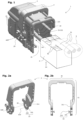
Fig.1 shows, in a perspective view partially on-scale, the connector housing with the lever mounted on it and positioned in the open position; -
Fig.2a and b show on-scale the lever ofFig.1 , respectively in a perspective and in a front view parallel to its pivoting axis; -
Fig.3 shows the connector ofFig.1 , in a view perpendicular to the pivoting axis, with the lever schematically represented in insertion position, open position, and closed position; -
Fig.4a and b show an on-scale detail of a lever joint of the connector ofFig.1 , viewed from the inside of its housing, respectively in front view and in perspective view, with the lever in the insertion position; -
Fig.5a and b show an on-scale detail of a lever joint of the connector ofFig.1 , viewed from the inside of its housing, respectively in front view and in perspective view, with the lever in the open position; -
Fig.6a and b show an on-scale detail of a lever joint of the connector ofFig.1 , viewed from the inside of its housing, respectively in front view and in perspective view, with the lever in closed position; -
Fig.7a shows a detail of a lever joint of the connector ofFig.1 , viewed in perspective, showing a possible position of the parting line in the area of the retention element for an example of design of a mould used for producing the lever, -
Fig.7b schematically shows from bottom the lever ofFig.7a with the position of an exemplary parting line in a case of a two-part mould separating into only two opposite demolding directions. - In the various figures, similar or identical elements have the same references.
-
Fig.1 partially shows of aconnector 1, which has aconnector housing 2 with alever 3 mounted on it. Theconnector 1 illustrated here is arranged, for example in a manner known in the prior art, with aninternal cavity 20 adapted to receiving acontact module 4 to be inserted M4 into theconnector housing 2. Thismodule 4, here shown only schematically, carries severalelectrical contacts 52, each of them being fixed to a differentelectrical conductor 51 within a cable 5. In this example, theconnector 1 and itscontact module 4 are designed for mating with a counter connector coming from a mating direction C4. However, such housing and lever may receive different kinds of electrical contacts, with or without a module, and different shapes and/or mating directions. - Also, functionality of the lever is not directly linked to the present embodiment, and may include mating aid or locking or other or a combination thereof.
- As illustrated also in
Fig.2a and Fig.2b , thelever 3 has two parallel andsymmetric lever arms 31, linked together by aknob 32 perpendicular to thelever arms 31. Eachlever arm 31 has apivot hole 39, which each receives apivot 29 extending from anexternal face 21 of theconnector housing 2. As illustrated inFig.3 , thelever 3 can be pivoted around the axis A29 of thepivot 29 andpivot holes 39. It may be noted that thepivot 29 of thehousing 2 does not extend outside thepivot hole 39 of the lever, and thus is protected from most potential shocks. Also, as the retention functionality is not assumed by thepivot 29 andpivot hole 39, the shape of them is simple and robust: the extremity of thepivot 29 is simply flat and tapered. Moreover,pivot hole 39 is here designed as a pass-through hole, but could also designed as a blind hole. - In an area separate from the pivotal joint 39-29, each
lever arm 31 bears a circular andcylindrical extension 331 which extends outside of itsinternal face 311, here in a perpendicular direction A33. Along this extension axis A33, theextension 331 is followed by aretention protrusion 332, here transversal to the extension axis A33, forming a T-shape of a circular perimeter. As can be seen inFig.1 andFig.5 toFig.6 , theextension 331 passes through a retention opening 22, and theretention protrusion 332 protrudes on two sides of the retention opening 22. Retention opening 22 is here disclosed as a pass-through opening, but could also be embodied as a blind opening. Extraction of theretention element 33, and hence spreading of thelever arms 31, is thus prevented by theedges 229 of said opening 22.Extension 331 andretention protrusion 332 thus form together aretention element 33 which is integral with thelever 3 and itslever arm 31. -
Fig.3 and Fig.4 toFig.6 illustrate different positions of thelever 3 in regard to theconnector housing 2, and various moves between them during the process of manufacturing and using theconnector 1. - In
Fig.4a and b is illustrated a detail of the pivot and retention areas, in a position P1 called assembly position, also shown schematically inFig.3 . In this assembly position P1, thepivot hole 39 of thelever arm 31 is in regard of thepivot 29 of thehousing 2. Also, theretention protrusion 332 is in regard of aportion 221 of theretention opening 22 where its edges are more widely spaced, called an insertion hole, so as to enable insertion of saidretention protrusion 332. In this position, thelever 3 is thus assembled to thehousing 2, such as by elastically spreading thelever arms 31 and then inserting bothpivot 29 into thepivot hole 39 andretention element 33 into theinsertion hole 221. - Once it is done,
lever 3 is rotated through a move L12 toward another position P2, called open position, schematically shown inFig.3 . As illustrated in detail inFig.5a and b , this move L12 is guided by theextension 331 of theretention element 33 along a portion in an arc of circle of theretention opening 22. In this portion, itsedges 229 are narrower than theretention protrusion 332 of theretention element 33, which can be seen extending over these retention edges 229. Thus, leverarms 31 are now retained by thehousing 2 and cannot be taken off it, so that the lever being may not be detached and lost. - The
connector 1, in its entirety or even just as the housing plus lever assembly, can then be handled transported and/or stored, individually or in bulk, with a limited risk of involuntary disassembly or breaking. This is still true once theconnector 1 has been mounted on a cable 5 or another element for preparing a whole subassembly, such as a whole harness ready to be connected, including during transporting or storing or handling such subassembly and during the operation of connecting said subassembly with a counter connector. - Afterward, when the
connector 1 is mated to its counter connector, thelever 3 is rotated to still another position P3, called closed position, in a move L23 schematically shown inFig.3 . In this closed position P3, as illustrated in detail inFig.6a and b ,extension 331 of theretention element 33 is in still another portion of theretention opening 22, also in a shape of an arc of circle, with itsedges 229 still narrower than theretention protrusion 332 of theretention element 33. Thus, leverarms 31 are again retained by thehousing 2 and cannot be taken off it, so that the lever being may again not be detached and lost. - As can be seen in
Fig.7a and Fig.7b , the shape ofsuch retention element 33 is compatible with a manufacturing process of thelever 3 by moulding, such as a plastic injection moulding, without causing a need for a supplementary mobile part of the mould, called slider or drawer or split. As a matter of fact, the shape of theretention protrusion 332 andextension 331 naturally have a sufficient angle of draft for making it possible to operate an unmolding movement in only two opposite direction D3a and D3b. Such mould configuration is here illustrated through anexemplary parting line 38, produced by the parting surface between the two parts of such a mould. - It may be noted that the
lever 3 may be mounted on and displaced on theconnector housing 2 without needing any access to theinternal cavity 20 of the latter, which offers a large freedom in designing the connector's shapes and cinematic. - Of course the disclosure is not limited to the examples which have just been described, and various adjustments may be made within the scope of the disclosure.
Claims (9)
- A connector (1) comprising a connector housing (2) carrying one or more electrical contacts,
which connector can be coupled to a counter-connector so as to ensure a connection of said contacts with one or more electrical contacts carried by said counter-connector,- said connector comprising at least one lever (3) arranged to assist or lock the connection with said counter-connector, comprising at least one lever-arm (31) that is linked with the connector housing by a joint (29), so as to be movable in regard of said connector housing, between at least :∘ a open position (P2), in which the counter-connector can be at least partially coupled to the connector, and∘ a closed position (P3), in which the counter-connector is fully coupled to the connector, and possibly locked therewith,- said connector further comprising at least a retention element (33) which is arranged to prevent said lever arm (31) from leaving its joint (29) by moving away from said connector housing,
characterized in that- said retention element (33) extends from the lever arm (31) on its face towards the connector housing (2), and has an extension (331) that extends within a retention opening (22) born by the connector housing,- where said retention element (33) has a transverse protrusion (332) that rests on the edges (229) of said retention opening (22), so as to retain the lever arm (31) against the connector housing (2),- both in the open position (P2) and in the closed position (P3). - Connector according to the preceding claim, characterized in that the retention opening (22) has a portion forming a insertion hole (221), wherein its edges (229) have a shape sufficiently wide to allow the protrusion (332) of the retention member (33) to pass through in a direction parallel to the extension (331) of the retention member,
and in that said insertion hole (221) is located within the retention opening (22) in a position different from the position of the retention element both in open position (P2) and in closed position (P3). - Connector according to any one of the preceding claims, characterized in that the lever arm (31) is pivotally mounted on the connector housing (1), and in that the retention opening (22) has a circular arc shape that is concentric with a pivot axis (A29) of the lever arm.
- Connector according to any of the preceding claims, characterized in that the lever (3) comprises two lever arms (31) that are linked together by a knob (32) and are each pivotally mounted on an external face (21) of the connector housing (2).
- Connector according to any of the preceding claims, characterized in that the transverse protrusion (332) of the retention element (33) has a T-shape in a section plane comprising an extension axis (A33) that is longitudinal to its extension (331).
- Connector to any of the preceding claims, characterized in that the transverse protrusion (332) of the retention element (33) has a shape that is oval or circular around an extension axis (A33) longitudinal to its extension (331).
- Connector according to any one of the preceding claims, characterized in that the lever arm (31) and its retention element (33) have a shape that is tapered on both sides of a same parting surface (38), thus allowing demoulding of the lever without its transverse protrusion (332) creating by itself a need for a moulding split.
- Method for manufacturing a connector (1), comprising the following steps :- manufacturing the housing (2) and the lever (3) of a connector (1) according to any one of claims 2 to 7,- assembling the lever (3) on the housing (2) by inserting the retention element(s) (33) into the insertion hole(s) (221), in an assembly position (P1),- moving (L12) the lever (3) from the assembly position (P1) to the open position (P2), thus allowing storage and delivery without the risk of the lever coming off the connector housing.
- Method for electrically connecting two cables to each other, comprising the following steps:- manufacturing a connector (1) according to the preceding claim,- providing the connector to a mounting station,- within the mounting station, mounting the connector (1) on a first cable by fixing therein its electrical contacts,- coupling the connector (1) to a counter connector mounted on a second cable, and moving (L23) the lever to the closed position (P3).
Priority Applications (4)
| Application Number | Priority Date | Filing Date | Title |
|---|---|---|---|
| EP23188554.2A EP4498531A1 (en) | 2023-07-28 | 2023-07-28 | Connector with retained lever, and method for producing and using the same |
| EP23192532.2A EP4498532A1 (en) | 2023-07-28 | 2023-08-21 | Electrical connector with assisted mating and overlapping course, and method for assembling it with its counter-connector |
| US18/779,881 US20250038458A1 (en) | 2023-07-28 | 2024-07-22 | Electrical connector with assisted mating and overlapping course, and method for assembling it with its counter-connector |
| CN202411011167.8A CN119447897A (en) | 2023-07-28 | 2024-07-26 | Electrical connector with auxiliary matching and overlapping line segments and method of assembling the same with a mating connector |
Applications Claiming Priority (1)
| Application Number | Priority Date | Filing Date | Title |
|---|---|---|---|
| EP23188554.2A EP4498531A1 (en) | 2023-07-28 | 2023-07-28 | Connector with retained lever, and method for producing and using the same |
Publications (1)
| Publication Number | Publication Date |
|---|---|
| EP4498531A1 true EP4498531A1 (en) | 2025-01-29 |
Family
ID=87551226
Family Applications (2)
| Application Number | Title | Priority Date | Filing Date |
|---|---|---|---|
| EP23188554.2A Pending EP4498531A1 (en) | 2023-07-28 | 2023-07-28 | Connector with retained lever, and method for producing and using the same |
| EP23192532.2A Pending EP4498532A1 (en) | 2023-07-28 | 2023-08-21 | Electrical connector with assisted mating and overlapping course, and method for assembling it with its counter-connector |
Family Applications After (1)
| Application Number | Title | Priority Date | Filing Date |
|---|---|---|---|
| EP23192532.2A Pending EP4498532A1 (en) | 2023-07-28 | 2023-08-21 | Electrical connector with assisted mating and overlapping course, and method for assembling it with its counter-connector |
Country Status (3)
| Country | Link |
|---|---|
| US (1) | US20250038458A1 (en) |
| EP (2) | EP4498531A1 (en) |
| CN (1) | CN119447897A (en) |
Citations (3)
| Publication number | Priority date | Publication date | Assignee | Title |
|---|---|---|---|---|
| US5647752A (en) * | 1994-05-12 | 1997-07-15 | Yazaki Corporation | Lever-type connector |
| US20120015547A1 (en) * | 2008-09-26 | 2012-01-19 | Joo Hyun Park | Electrical connector assembly having locking device |
| US20130017697A1 (en) * | 2010-04-02 | 2013-01-17 | Yazaki Corporation | Lever fitting-type connector |
-
2023
- 2023-07-28 EP EP23188554.2A patent/EP4498531A1/en active Pending
- 2023-08-21 EP EP23192532.2A patent/EP4498532A1/en active Pending
-
2024
- 2024-07-22 US US18/779,881 patent/US20250038458A1/en active Pending
- 2024-07-26 CN CN202411011167.8A patent/CN119447897A/en active Pending
Patent Citations (3)
| Publication number | Priority date | Publication date | Assignee | Title |
|---|---|---|---|---|
| US5647752A (en) * | 1994-05-12 | 1997-07-15 | Yazaki Corporation | Lever-type connector |
| US20120015547A1 (en) * | 2008-09-26 | 2012-01-19 | Joo Hyun Park | Electrical connector assembly having locking device |
| US20130017697A1 (en) * | 2010-04-02 | 2013-01-17 | Yazaki Corporation | Lever fitting-type connector |
Also Published As
| Publication number | Publication date |
|---|---|
| CN119447897A (en) | 2025-02-14 |
| EP4498532A1 (en) | 2025-01-29 |
| US20250038458A1 (en) | 2025-01-30 |
Similar Documents
| Publication | Publication Date | Title |
|---|---|---|
| JP6710310B2 (en) | Connector system with connector position guarantee | |
| KR100198774B1 (en) | Floating panel mount system for electrical connectors | |
| JP2881568B2 (en) | Electrical connector with terminal position assurance mechanism | |
| EP0760542B1 (en) | Electrical connector with improved latching system | |
| US7396240B2 (en) | Electrical connector with a locking mechanism | |
| US20080166909A1 (en) | Electrical connection box and assembling method of electrical connection box | |
| US20180083385A1 (en) | Lever type connector | |
| US9407038B2 (en) | Electrical distribution center | |
| KR20180117548A (en) | Electrical connector with lever | |
| US6846195B2 (en) | Housing for a coaxial connector element, and a coaxial connector element | |
| CN115642432A (en) | Electrical junction box | |
| US6783380B1 (en) | Low insertion force connector system | |
| EP2973880B1 (en) | Method of manufacturing a housing and a lever | |
| CN107453098B (en) | electrical connector | |
| EP4498532A1 (en) | Electrical connector with assisted mating and overlapping course, and method for assembling it with its counter-connector | |
| US7731519B1 (en) | Adaptable universal electrical connector system particularly adapted for use in repair or replacement of electrical components such as relays, solenoids and the like | |
| EP1614196B1 (en) | Lever type electrical connector assembly with improved locking means | |
| US12261395B2 (en) | Electrical connector system with miniaturized connector position assurance member | |
| US20220384993A1 (en) | Lever Type Connector and Connector System with Lever Type Connector | |
| EP1611647A1 (en) | Lever type electrical connector assembly with improved guide means | |
| US7618278B2 (en) | Closed housing for a locking element of a plug-in connection | |
| EP1401064B1 (en) | An adaptor for electrical connection between connectors having different numbers of poles | |
| US20260142413A1 (en) | Connector structure | |
| EP4611183A1 (en) | Connector with lever latched in delivery position, method for assembling and using it | |
| CN111033906B (en) | Holding structure of connector |
Legal Events
| Date | Code | Title | Description |
|---|---|---|---|
| PUAI | Public reference made under article 153(3) epc to a published international application that has entered the european phase |
Free format text: ORIGINAL CODE: 0009012 |
|
| STAA | Information on the status of an ep patent application or granted ep patent |
Free format text: STATUS: THE APPLICATION HAS BEEN PUBLISHED |
|
| AK | Designated contracting states |
Kind code of ref document: A1 Designated state(s): AL AT BE BG CH CY CZ DE DK EE ES FI FR GB GR HR HU IE IS IT LI LT LU LV MC ME MK MT NL NO PL PT RO RS SE SI SK SM TR |
|
| STAA | Information on the status of an ep patent application or granted ep patent |
Free format text: STATUS: REQUEST FOR EXAMINATION WAS MADE |
|
| 17P | Request for examination filed |
Effective date: 20250701 |