EP4498501A1 - Battery module and battery pack including same - Google Patents
Battery module and battery pack including same Download PDFInfo
- Publication number
- EP4498501A1 EP4498501A1 EP23900817.0A EP23900817A EP4498501A1 EP 4498501 A1 EP4498501 A1 EP 4498501A1 EP 23900817 A EP23900817 A EP 23900817A EP 4498501 A1 EP4498501 A1 EP 4498501A1
- Authority
- EP
- European Patent Office
- Prior art keywords
- electrode lead
- busbar
- battery
- battery cell
- battery module
- Prior art date
- Legal status (The legal status is an assumption and is not a legal conclusion. Google has not performed a legal analysis and makes no representation as to the accuracy of the status listed.)
- Pending
Links
Images







Classifications
-
- H—ELECTRICITY
- H01—ELECTRIC ELEMENTS
- H01M—PROCESSES OR MEANS, e.g. BATTERIES, FOR THE DIRECT CONVERSION OF CHEMICAL ENERGY INTO ELECTRICAL ENERGY
- H01M50/00—Constructional details or processes of manufacture of the non-active parts of electrochemical cells other than fuel cells, e.g. hybrid cells
- H01M50/50—Current conducting connections for cells or batteries
- H01M50/502—Interconnectors for connecting terminals of adjacent batteries; Interconnectors for connecting cells outside a battery casing
- H01M50/507—Interconnectors for connecting terminals of adjacent batteries; Interconnectors for connecting cells outside a battery casing comprising an arrangement of two or more busbars within a container structure, e.g. busbar modules
-
- H—ELECTRICITY
- H01—ELECTRIC ELEMENTS
- H01M—PROCESSES OR MEANS, e.g. BATTERIES, FOR THE DIRECT CONVERSION OF CHEMICAL ENERGY INTO ELECTRICAL ENERGY
- H01M50/00—Constructional details or processes of manufacture of the non-active parts of electrochemical cells other than fuel cells, e.g. hybrid cells
- H01M50/10—Primary casings; Jackets or wrappings
- H01M50/102—Primary casings; Jackets or wrappings characterised by their shape or physical structure
- H01M50/105—Pouches or flexible bags
-
- H—ELECTRICITY
- H01—ELECTRIC ELEMENTS
- H01M—PROCESSES OR MEANS, e.g. BATTERIES, FOR THE DIRECT CONVERSION OF CHEMICAL ENERGY INTO ELECTRICAL ENERGY
- H01M50/00—Constructional details or processes of manufacture of the non-active parts of electrochemical cells other than fuel cells, e.g. hybrid cells
- H01M50/10—Primary casings; Jackets or wrappings
- H01M50/172—Arrangements of electric connectors penetrating the casing
- H01M50/174—Arrangements of electric connectors penetrating the casing adapted for the shape of the cells
- H01M50/178—Arrangements of electric connectors penetrating the casing adapted for the shape of the cells for pouch or flexible bag cells
-
- H—ELECTRICITY
- H01—ELECTRIC ELEMENTS
- H01M—PROCESSES OR MEANS, e.g. BATTERIES, FOR THE DIRECT CONVERSION OF CHEMICAL ENERGY INTO ELECTRICAL ENERGY
- H01M50/00—Constructional details or processes of manufacture of the non-active parts of electrochemical cells other than fuel cells, e.g. hybrid cells
- H01M50/20—Mountings; Secondary casings or frames; Racks, modules or packs; Suspension devices; Shock absorbers; Transport or carrying devices; Holders
- H01M50/204—Racks, modules or packs for multiple batteries or multiple cells
- H01M50/207—Racks, modules or packs for multiple batteries or multiple cells characterised by their shape
- H01M50/211—Racks, modules or packs for multiple batteries or multiple cells characterised by their shape adapted for pouch cells
-
- H—ELECTRICITY
- H01—ELECTRIC ELEMENTS
- H01M—PROCESSES OR MEANS, e.g. BATTERIES, FOR THE DIRECT CONVERSION OF CHEMICAL ENERGY INTO ELECTRICAL ENERGY
- H01M50/00—Constructional details or processes of manufacture of the non-active parts of electrochemical cells other than fuel cells, e.g. hybrid cells
- H01M50/20—Mountings; Secondary casings or frames; Racks, modules or packs; Suspension devices; Shock absorbers; Transport or carrying devices; Holders
- H01M50/249—Mountings; Secondary casings or frames; Racks, modules or packs; Suspension devices; Shock absorbers; Transport or carrying devices; Holders specially adapted for aircraft or vehicles, e.g. cars or trains
-
- H—ELECTRICITY
- H01—ELECTRIC ELEMENTS
- H01M—PROCESSES OR MEANS, e.g. BATTERIES, FOR THE DIRECT CONVERSION OF CHEMICAL ENERGY INTO ELECTRICAL ENERGY
- H01M50/00—Constructional details or processes of manufacture of the non-active parts of electrochemical cells other than fuel cells, e.g. hybrid cells
- H01M50/50—Current conducting connections for cells or batteries
-
- H—ELECTRICITY
- H01—ELECTRIC ELEMENTS
- H01M—PROCESSES OR MEANS, e.g. BATTERIES, FOR THE DIRECT CONVERSION OF CHEMICAL ENERGY INTO ELECTRICAL ENERGY
- H01M50/00—Constructional details or processes of manufacture of the non-active parts of electrochemical cells other than fuel cells, e.g. hybrid cells
- H01M50/50—Current conducting connections for cells or batteries
- H01M50/502—Interconnectors for connecting terminals of adjacent batteries; Interconnectors for connecting cells outside a battery casing
- H01M50/503—Interconnectors for connecting terminals of adjacent batteries; Interconnectors for connecting cells outside a battery casing characterised by the shape of the interconnectors
-
- H—ELECTRICITY
- H01—ELECTRIC ELEMENTS
- H01M—PROCESSES OR MEANS, e.g. BATTERIES, FOR THE DIRECT CONVERSION OF CHEMICAL ENERGY INTO ELECTRICAL ENERGY
- H01M50/00—Constructional details or processes of manufacture of the non-active parts of electrochemical cells other than fuel cells, e.g. hybrid cells
- H01M50/50—Current conducting connections for cells or batteries
- H01M50/531—Electrode connections inside a battery casing
- H01M50/533—Electrode connections inside a battery casing characterised by the shape of the leads or tabs
-
- H—ELECTRICITY
- H01—ELECTRIC ELEMENTS
- H01M—PROCESSES OR MEANS, e.g. BATTERIES, FOR THE DIRECT CONVERSION OF CHEMICAL ENERGY INTO ELECTRICAL ENERGY
- H01M50/00—Constructional details or processes of manufacture of the non-active parts of electrochemical cells other than fuel cells, e.g. hybrid cells
- H01M50/50—Current conducting connections for cells or batteries
- H01M50/531—Electrode connections inside a battery casing
- H01M50/536—Electrode connections inside a battery casing characterised by the method of fixing the leads to the electrodes, e.g. by welding
-
- H—ELECTRICITY
- H01—ELECTRIC ELEMENTS
- H01M—PROCESSES OR MEANS, e.g. BATTERIES, FOR THE DIRECT CONVERSION OF CHEMICAL ENERGY INTO ELECTRICAL ENERGY
- H01M50/00—Constructional details or processes of manufacture of the non-active parts of electrochemical cells other than fuel cells, e.g. hybrid cells
- H01M50/50—Current conducting connections for cells or batteries
- H01M50/543—Terminals
- H01M50/547—Terminals characterised by the disposition of the terminals on the cells
- H01M50/548—Terminals characterised by the disposition of the terminals on the cells on opposite sides of the cell
-
- H—ELECTRICITY
- H01—ELECTRIC ELEMENTS
- H01M—PROCESSES OR MEANS, e.g. BATTERIES, FOR THE DIRECT CONVERSION OF CHEMICAL ENERGY INTO ELECTRICAL ENERGY
- H01M50/00—Constructional details or processes of manufacture of the non-active parts of electrochemical cells other than fuel cells, e.g. hybrid cells
- H01M50/50—Current conducting connections for cells or batteries
- H01M50/502—Interconnectors for connecting terminals of adjacent batteries; Interconnectors for connecting cells outside a battery casing
- H01M50/514—Methods for interconnecting adjacent batteries or cells
- H01M50/516—Methods for interconnecting adjacent batteries or cells by welding, soldering or brazing
-
- Y—GENERAL TAGGING OF NEW TECHNOLOGICAL DEVELOPMENTS; GENERAL TAGGING OF CROSS-SECTIONAL TECHNOLOGIES SPANNING OVER SEVERAL SECTIONS OF THE IPC; TECHNICAL SUBJECTS COVERED BY FORMER USPC CROSS-REFERENCE ART COLLECTIONS [XRACs] AND DIGESTS
- Y02—TECHNOLOGIES OR APPLICATIONS FOR MITIGATION OR ADAPTATION AGAINST CLIMATE CHANGE
- Y02E—REDUCTION OF GREENHOUSE GAS [GHG] EMISSIONS, RELATED TO ENERGY GENERATION, TRANSMISSION OR DISTRIBUTION
- Y02E60/00—Enabling technologies; Technologies with a potential or indirect contribution to GHG emissions mitigation
- Y02E60/10—Energy storage using batteries
Definitions
- a conventional battery module 10 includes a battery cell stack 12 in which a plurality of battery cells 11 are stacked, and busbar frames 30 disposed on both sides of the battery cell stack 12.
- busbar frame 30 may be mounted with a busbar 40.
- the busbar 40 is for providing electrical connection between the plurality of battery cells 11.
- the electrode lead 11L of the battery cell 11 passes through a slit formed in the busbar frame 30, and then can be bent and connected to the busbar 40. In some cases, the electrode lead 11L may also pass through a slit 40S formed in the busbar 40.
- the method is not limited as long as electrical connection is available, and for example, they may be connected by welding junction.
- the battery cells 11 may be electrically connected in series or parallel via the busbar 40.
- connection configuration of the battery cells 11 as mentioned above may be broken by tensile force. This will be explained with reference to FIG. 3 .
- FIG. 3 is a cross-sectional view for explaining breakage of an electrode tab or breakage of a connecting portion between an electrode tab and an electrode lead in a conventional battery module.
- the electrode lead 11L protrudes to the outside of the cell case 11C, passes through a slit 30S of the busbar frame 30 and a slit 40S of the busbar 40 as mentioned above, and then can be bent and connected to the busbar 40.
- FIG. 3 shows only the case where one electrode lead 11L protruding from one battery cell 11 is joined to the busbar 40, there is also a case where a plurality of electrode leads 11L protruding from multiple battery cells 11 are joined to one busbar 40.
- the electrode leads 11L are bent to form a bent portion 11LB.
- the length of the electrode leads 11L must be set differently for each battery cell 11. Therefore, the conventional battery module 10 essentially requires a process of cutting the electrode lead 11L and a process of bending the electrode lead 11L.
- a tensile force TF is generated in the electrode lead 11L. Due to this tensile force TF, stress may be concentrated on the electrode tab 11t or the connecting portion between the electrode tab 11t and the electrode lead 11L. Ultimately, in the worst cases, there may be a problem that the electrode tab 11t itself is broken or the connecting portion between the electrode tab 11t and the electrode lead 11L is broken. Since this is an important issue that can be related to the risk of fire due to internal short circuits, there is a need to develop a technology that can prevent breakage of the electrode tab or breakage of the connecting portion between the electrode tab and the electrode lead.
- a battery module comprises: a battery cell stack in which battery cells are stacked along a first direction; and at least one busbar located on one side or both sides of the battery cell stack.
- An electrode lead protrudes from the battery cell along a second direction perpendicular to the first direction.
- the busbar comprises a first portion, and a second portion that extends from the first portion at a certain angle with one surface of the first portion, and the electrode lead is joined to the second portion.
- the battery cell may be a pouch-type battery cell, and in the battery cell stack, the battery cells may be stacked in an upright state so that one-side surfaces of the battery cells faces each other.
- the electrode lead may be welded and joined to the second portion.
- the battery module may further comprise a busbar frame located between the battery cell stack and the busbar, and the busbar is mounted on the busbar frame.
- the busbar frame may be formed with a slit, and the electrode lead passes through the slit and may be joined to the second portion of the busbar.
- the electrode lead may be formed with a bead portion protruding in a direction different from the second direction.
- the bead portion may protrude from a middle portion of the electrode lead in a direction parallel to the first direction.
- the bead portion may be a portion formed by bending the electrode lead at least three times.
- a joining portion which is a portion where the electrode lead and the second portion are joined, may be provided at a portion where the bead portion is connected to the electrode lead.
- the portion where the bead portion is connected to the electrode lead may be irradiated with a laser to form the joining portion.
- the battery module may further comprise a module frame in which the battery cell stack is housed.
- a battery pack comprising the battery module.
- the busbar is designed to include a first portion and a second portion, so that the electrode lead can be joined to the busbar without bending.
- a bending portion is not formed in the electrode lead, tensile force due to bending does not act on the electrode lead, and it is possible to prevent breakage of the electrode tab or breakage of the connecting portion between the electrode tab and the electrode lead.
- a bead portion protruding from the electrode lead can be formed. Even if a bending portion is not formed in the electrode lead, the bead portion allows stable junction between the electrode lead and the busbar.
- planar it means when a target portion is viewed from the upper side
- cross-sectional it means when a target portion is viewed from the side of a cross section cut vertically.
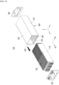
- FIG. 4 is an exploded perspective view showing a battery module according to an embodiment of the present disclosure.
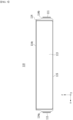
- FIG. 5 is a plan view showing one of the battery cells included in the battery module of FIG. 4 .
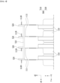
- FIG. 6 is a partial view showing the battery cell stack and busbar included in the battery module of FIG. 4 .
- the battery module 100 includes a battery cell stack 120 in which battery cells 110 are stacked along a first direction d1, and at least one busbar 500 located on one side or both sides of the battery cell stack 120.
- the battery cell 110 can be produced by joining both ends 114a and 114b of a pouch case 114 and one side part 114c connecting them in a state in which an electrode assembly (not shown) is housed in a pouch case 114.
- the battery cell 110 according to the present embodiment has a total of three sealing portions, the sealing portions have a structure that is sealed by a method such as fusion, and the remaining other one side part may be composed of a folding part 115. That is, the battery cell 110 according to the present embodiment may be a pouch-type battery cell configured to house an electrode assembly inside the pouch case 114 and seal the outer peripheral part of the pouch case 114.
Landscapes
- Chemical & Material Sciences (AREA)
- Chemical Kinetics & Catalysis (AREA)
- Electrochemistry (AREA)
- General Chemical & Material Sciences (AREA)
- Engineering & Computer Science (AREA)
- Aviation & Aerospace Engineering (AREA)
- Connection Of Batteries Or Terminals (AREA)
- Battery Mounting, Suspending (AREA)
Abstract
Description
- This application claims the benefit of
Korean Patent Application No. 10-2022-0167843 filed on December 5, 2022 - The present disclosure relates to a battery module and a battery pack including the same, and more particularly, to a battery module having a novel connection configuration of electrode leads and busbars, and a battery pack including the same.
- In modern society, as portable devices such as a mobile phone, a notebook computer, a camcorder and a digital camera has been daily used, the development of technologies in the fields related to mobile devices as described above has been activated. In addition, chargeable/dischargeable secondary batteries are used as a power source for an electric vehicle (EV), a hybrid electric vehicle (HEV), a plug-in hybrid electric vehicle (P-HEV) and the like, in an attempt to solve air pollution and the like caused by existing gasoline vehicles using fossil fuel. Therefore, the demand for development of the secondary battery is growing.
- Generally, the lithium secondary battery may be classified into a can-type secondary battery in which the electrode assembly is mounted in a metal can, and a pouch-type secondary battery in which the electrode assembly is mounted in a pouch of an aluminum laminate sheet, depending on the shape of the exterior material.
- In the case of a secondary battery used for small-sized devices, two to three battery cells are disposed, but in the case of a secondary battery used for a medium- and large-sized device such as automobiles, a battery module in which a plurality of battery cells are electrically connected is used. In such a battery module, a plurality of battery cells are connected to each other in series or parallel to form a cell assembly, thereby improving capacity and output. Further, one or more battery modules can be mounted together with various control and protection systems such as a BDU(Battery Disconnect Unit), a BMS(Battery Management System), and a cooling system to form a battery pack.
- A conventional battery module may utilize a busbar and a busbar frame for providing electrical connection between multiple battery cells. The structure of the busbar and busbar frame used in a conventional battery module will be described below with reference to
FIGS. 1 and2 . -
FIG. 1 is a perspective view showing a conventional battery module.FIG. 2 is a partial view which enlarges and shows a section of "A" inFIG. 1 . In particular,FIG. 1 shows the state in which the battery module is erected to show the appearance of the busbar frame and busbar. - Referring to
FIGS. 1 and2 , aconventional battery module 10 includes abattery cell stack 12 in which a plurality ofbattery cells 11 are stacked, andbusbar frames 30 disposed on both sides of thebattery cell stack 12. Such abusbar frame 30 may be mounted with abusbar 40. - The
busbar 40 is for providing electrical connection between the plurality ofbattery cells 11. The electrode lead 11L of thebattery cell 11 passes through a slit formed in thebusbar frame 30, and then can be bent and connected to thebusbar 40. In some cases, theelectrode lead 11L may also pass through aslit 40S formed in thebusbar 40. - When connecting between the
electrode lead 11L and thebusbar 40, the method is not limited as long as electrical connection is available, and for example, they may be connected by welding junction. Thebattery cells 11 may be electrically connected in series or parallel via thebusbar 40. - The connection configuration of the
battery cells 11 as mentioned above may be broken by tensile force. This will be explained with reference toFIG. 3 . -
FIG. 3 is a cross-sectional view for explaining breakage of an electrode tab or breakage of a connecting portion between an electrode tab and an electrode lead in a conventional battery module. - Referring to
FIG. 3 , thebattery cell 11 can be produced by housing theelectrode assembly 11A inside a pouch-shaped cell case 11C and then sealing the outer peripheral portion of thecell case 11C to form asealing portion 11S. Theelectrode assembly 11A may include electrodes and a separator disposed between the electrodes. Respective electrodes includeelectrode tabs 11t, wherein theelectrode tabs 11t may be connected to theelectrode lead 11L by a method such as welding. - The
electrode lead 11L protrudes to the outside of thecell case 11C, passes through aslit 30S of thebusbar frame 30 and aslit 40S of thebusbar 40 as mentioned above, and then can be bent and connected to thebusbar 40. - At this time, welding is performed by bringing the
electrode lead 11L into close contact with the surface of thebusbar 40. AlthoughFIG. 3 shows only the case where one electrode lead 11L protruding from onebattery cell 11 is joined to thebusbar 40, there is also a case where a plurality of electrode leads 11L protruding frommultiple battery cells 11 are joined to onebusbar 40. In order to bring the electrode leads 11L into close contact with the surface of thebusbar 40, the electrode leads 11L are bent to form a bent portion 11LB. Further, in order to bring multiple electrode leads 11L into close contact with the surface of thebusbar 40, the length of the electrode leads 11L must be set differently for eachbattery cell 11. Therefore, theconventional battery module 10 essentially requires a process of cutting theelectrode lead 11L and a process of bending theelectrode lead 11L. - Further, in the process of bending the
electrode lead 11L, a tensile force TF is generated in theelectrode lead 11L. Due to this tensile force TF, stress may be concentrated on theelectrode tab 11t or the connecting portion between theelectrode tab 11t and theelectrode lead 11L. Ultimately, in the worst cases, there may be a problem that theelectrode tab 11t itself is broken or the connecting portion between theelectrode tab 11t and theelectrode lead 11L is broken. Since this is an important issue that can be related to the risk of fire due to internal short circuits, there is a need to develop a technology that can prevent breakage of the electrode tab or breakage of the connecting portion between the electrode tab and the electrode lead. - It is an object of the present disclosure to provide a battery module having a novel connection configuration of electrode leads and busbars so as to prevent breakage of the electrode tab itself or breakage of the connecting portion between the electrode tab and the electrode lead, and a battery pack including the same.
- However, the technical problems to be solved by embodiments of the present disclosure are not limited to the above-mentioned problems, and can be variously expanded within the scope of the technical idea included in the present disclosure.
- A battery module according to an embodiment of the present disclosure comprises: a battery cell stack in which battery cells are stacked along a first direction; and at least one busbar located on one side or both sides of the battery cell stack. An electrode lead protrudes from the battery cell along a second direction perpendicular to the first direction. The busbar comprises a first portion, and a second portion that extends from the first portion at a certain angle with one surface of the first portion, and the electrode lead is joined to the second portion.
- The battery cell may be a pouch-type battery cell, and in the battery cell stack, the battery cells may be stacked in an upright state so that one-side surfaces of the battery cells faces each other.
- The second portion may extend so that one surface of the second portion is perpendicular to one surface of the first portion.
- One surface of the first portion may be parallel to the first direction, and one surface of the second portion is parallel to the second direction.
- The electrode lead may be welded and joined to the second portion.
- The busbar may be formed with an open portion, and at least one of the electrode leads may be joined to the second portion while passing through the open portion.
- The battery module may further comprise a busbar frame located between the battery cell stack and the busbar, and the busbar is mounted on the busbar frame. The busbar frame may be formed with a slit, and the electrode lead passes through the slit and may be joined to the second portion of the busbar.
- The electrode lead may be formed with a bead portion protruding in a direction different from the second direction.
- The bead portion may protrude from a middle portion of the electrode lead in a direction parallel to the first direction.
- The bead portion may be a portion formed by bending the electrode lead at least three times.
- A joining portion, which is a portion where the electrode lead and the second portion are joined, may be provided at a portion where the bead portion is connected to the electrode lead.
- The portion where the bead portion is connected to the electrode lead may be irradiated with a laser to form the joining portion.
- The battery module may further comprise a module frame in which the battery cell stack is housed.
- According to an embodiment of the present disclosure, there is provided a battery pack comprising the battery module.
- According to embodiments of the present disclosure, the busbar is designed to include a first portion and a second portion, so that the electrode lead can be joined to the busbar without bending. Thereby, since a bending portion is not formed in the electrode lead, tensile force due to bending does not act on the electrode lead, and it is possible to prevent breakage of the electrode tab or breakage of the connecting portion between the electrode tab and the electrode lead.
- Since a bending portion is not formed in the electrode lead, a process of bending the electrode lead is not necessary. Further, since respective battery cells can be located regularly from the joining portion between the electrode lead and the busbar, a process of cutting the electrode lead is also not necessary.
- In addition, according to embodiments of the present disclosure, a bead portion protruding from the electrode lead can be formed. Even if a bending portion is not formed in the electrode lead, the bead portion allows stable junction between the electrode lead and the busbar.
- Effects obtainable from the present disclosure may be not limited by the above mentioned effects. And, other effects not mentioned herein can be clearly understood from the description of the claims by those skilled in the art.
-
-
FIG. 1 is a perspective view showing a conventional battery module; -
FIG. 2 is a partial view which enlarges and shows a section of "A" inFIG. 1 ; -
FIG. 3 is a cross-sectional view for explaining breakage of an electrode tab or breakage of a connecting portion between an electrode tab and an electrode lead in a conventional battery module; -
FIG. 4 is an exploded perspective view showing a battery module according to an embodiment of the present disclosure; -
FIG. 5 is a plan view showing one of the battery cells included in the battery module ofFIG. 4 ; -
FIG. 6 is a partial view showing the battery cell stack and busbar included in the battery module ofFIG. 4 ; -
FIG. 7 is a partial view which enlarges and shows the joining portion between the electrode leads of the battery cells and the busbar inFIG. 6 ; -
FIG. 8 is a cross-sectional view showing a cross-section taken along the cutting line B-B' ofFIG. 6 ; -
FIG. 9 is a perspective view showing a busbar according to an embodiment of the present disclosure; -
FIGS. 10 and11 are diagrams showing electrode leads of a battery cell according to an embodiment of the present disclosure, respectively; -
FIGS. 12 and13 are diagrams showing the process of joining an electrode lead and a busbar according to an embodiment of the present disclosure, respectively; -
FIG. 14 is a diagram showing an electrode lead of a battery cell according to another embodiment of the present disclosure; and -
FIG. 15 is a perspective view showing a busbar frame according to an embodiment of the present disclosure. - Hereinafter, various embodiments of the present disclosure will be described in detail with reference to the accompanying drawings so that those skilled in the art can easily carry out them. The present disclosure may be modified in various different ways, and is not limited to the embodiments set forth herein.
- Portions that are irrelevant to the description will be omitted to clearly describe the present disclosure, and same reference numerals designate same or like elements throughout the description.
- Further, in the drawings, the size and thickness of each element are arbitrarily illustrated for convenience of description, and the present disclosure is not necessarily limited to those illustrated in the drawings. In the drawings, the thickness of layers, regions, etc. are exaggerated for clarity. In the drawings, for convenience of description, the thicknesses of a part and an area are exaggerated.
- Further, it will be understood that when an element such as a layer, film, region, or plate is referred to as being "on" or "above" another element, it can be directly on the other element or intervening elements may also be present. In contrast, when an element is referred to as being "directly on" another element, it means that other intervening elements are not present. Further, a certain part being located "above" or "on" a reference portion means the certain part being located above or below the reference portion and does not particularly mean the certain part "above" or "on" toward an opposite direction of gravity.
- Further, throughout the description, when a portion is referred to as "including" or "comprising" a certain component, it means that the portion can further include other components, without excluding the other components, unless otherwise stated.
- Further, throughout the description, when it is referred to as "planar", it means when a target portion is viewed from the upper side, and when it is referred to as "cross-sectional", it means when a target portion is viewed from the side of a cross section cut vertically.
-
FIG. 4 is an exploded perspective view showing a battery module according to an embodiment of the present disclosure.FIG. 5 is a plan view showing one of the battery cells included in the battery module ofFIG. 4 .FIG. 6 is a partial view showing the battery cell stack and busbar included in the battery module ofFIG. 4 . - Referring to
FIGS. 4 to 6 , thebattery module 100 according to an embodiment of the present disclosure includes abattery cell stack 120 in whichbattery cells 110 are stacked along a first direction d1, and at least onebusbar 500 located on one side or both sides of thebattery cell stack 120. - The
busbar 500 is a medium for electrical connection between the electrode leads 111 of thebattery cells 110, and preferably includes a metal material. Whether or not thebusbar 500 is located on one side or both sides of thebattery cell stack 120 is determined depending on whether theelectrode lead 111 of thebattery cell 110 protrudes in only one direction or whether it protrudes in both directions. Below, thebattery cell 110 according to the present embodiment will be first specifically described. - The
battery cell 110 may be a pouch-type battery cell, and may have a rectangular sheet shape. Thebattery cell 110 can be formed by housing an electrode assembly in a pouch case of a laminate sheet including a resin layer and a metal layer, and then adhering the outer peripheral part of the pouch case. Specifically, thebattery cell 110 may have a structure in which two electrode leads 111 face each other and protrude from oneend 114a and theother end 114b of the cellmain body 113, respectively. As another embodiment, a structure in which the electrode leads 111 of thebattery cells 110 all protrude in one direction is also available. One of the electrode leads 111 is a positive electrode lead, and the other is a negative electrode lead. - The
battery cell 110 can be produced by joining bothends pouch case 114 and oneside part 114c connecting them in a state in which an electrode assembly (not shown) is housed in apouch case 114. In other words, thebattery cell 110 according to the present embodiment has a total of three sealing portions, the sealing portions have a structure that is sealed by a method such as fusion, and the remaining other one side part may be composed of afolding part 115. That is, thebattery cell 110 according to the present embodiment may be a pouch-type battery cell configured to house an electrode assembly inside thepouch case 114 and seal the outer peripheral part of thepouch case 114. -
Such battery cells 110 are stacked along the first direction d1 to form thebattery cell stack 120. Specifically, in thebattery cell stack 120, thebattery cells 110 may be stacked along the first direction d1 in an upright state so that one-side surfaces of thebattery cells 110 face each other. - At this time, the electrode leads 111 protrude from the battery cell along the second direction d2 perpendicular to the first direction d1. Thereby, the
busbar 500 may be located on one side in the second direction d2 with respect to thebattery cell stack 120. - In the present disclosure, the first direction d1 is shown to be the y-axis direction, and the second direction d2 is shown to be the x-axis direction.
- On the other hand, if the electrode leads 111 of the
battery cell 110 is configured to protrude in both directions from thebattery cell 110, other electrode leads 111 can protrude in a direction opposite to the second direction d2, that is, in the -x axis direction. Thereby,other busbars 500 may also be located on one side of thebattery cell stack 120 in a direction opposite to the second direction d2. - Below, the configuration of the busbar and the junction between the busbar and the electrode lead according to the present embodiment will be described in detail.
-
FIG. 7 is a partial view which enlarges and shows the joining portion between the electrode leads of the battery cells and the busbar inFIG. 6 .FIG. 8 is a cross-sectional view showing a cross-section taken along the cutting line B-B' ofFIG. 6 .FIG. 9 is a perspective view showing a busbar according to an embodiment of the present disclosure. - Referring to
FIGS. 6 to 9 together, thebusbar 500 according to the present embodiment includes afirst portion 510, and asecond part 520 that extends from thefirst portion 510 at a constant angle with one surface of thefirst portion 510, wherein theelectrode lead 111 of thebattery cell 110 is joined to thesecond portion 520. As previously described, thebusbar 500 is a medium for electrical connection between thebattery cells 110, which is a member that is joined to theelectrode lead 111 of thebattery cell 110. - As one example, the
second portion 520 may extend at an angle of 45 degrees or more and 135 degrees or less with one surface of thefirst portion 510. More specifically, thesecond portion 520 may be extended so that one surface of thesecond portion 520 is perpendicular to one surface of thefirst portion 510. In particular, one surface of thefirst portion 510 may be parallel to the first direction d1, and one surface of thesecond portion 520 may be parallel to the second direction d2. In other words, one surface of thefirst portion 510 may be parallel to the direction in which thebattery cells 110 are stacked, and thesecond portion 520 may be parallel to the direction in which theelectrode lead 111 protrudes from thebattery cell 110. - In the present embodiment, the
busbar 500 is not composed of only thefirst portion 510, but further includes asecond portion 520 that makes a constant angle with thefirst portion 510, and theelectrode lead 111 is joined to thissecond portion 520. - If the busbar consists of only the first portion, it has a structure similar to the
conventional busbar 40 described inFIGS. 1 to 3 . When theelectrode lead 11L is joined to thebusbar 40 as mentioned above, theelectrode lead 11L is bent to form the bent portion 11LB in order to bring theelectrode lead 11L into close contact with the surface of thebusbar 40. Thereby, a process of cutting theelectrode lead 11L and a process of bending theelectrode lead 11L were essentially required, and breakage was generated in theelectrode lead 11L due to the tensile force TF generated in the process of bending theelectrode lead 11L. - On the other hand, in the case of the
busbar 500 according to the present embodiment, asecond portion 520 is further provided, and theelectrode lead 111 is joined to thissecond portion 520. Therefore, in the process of joining theelectrode lead 111 to thebusbar 500, there is no need to bend theelectrode lead 111. Since the tensile force due to bending does not act on theelectrode lead 111, it is possible to prevent breakage of the electrode tab or breakage of the connecting portion between the electrode tab and the electrode lead. - Further, since the process of bending the electrode lead is not necessary and
respective battery cells 110 can be located regularly from the joining portion between theelectrode lead 111 and thebusbar 500, the process of cutting theelectrode lead 111 is also not necessary. In other words, since partial processes can be eliminated, product production costs can be reduced, and productivity can be improved. - On the other hand, the joining method between the
electrode lead 111 and thesecond portion 520 is not particularly limited as long as electrical connection between theelectrode lead 111 and thesecond portion 520 is available. As one example, theelectrode lead 111 may be welded and joined to thesecond portion 520. That is, theelectrode lead 111 may be formed with a joining portion due to welding junction. The welding junction and the joining portion will be described again below along withFIGS. 10 to 13 . - The
busbar 500 according to the present embodiment may be formed with anopen portion 500P, and at least one of the electrode leads 111 may be bonded to thesecond portion 520 while passing through theopen portion 500P. In particular, thefirst portion 510 of thebusbar 500 may be formed with anopen portion 500P. Multiplesecond portions 520 may be provided on onebusbar 500, and anopen portion 500P may be provided in order to join theelectrode lead 111 to thesecond portion 520 located on the central side rather than the outermost side. Further, the other electrode leads 111 may be joined to thesecond portion 520 without passing through theopen portion 500P, as illustrated. In particular, some of the electrode leads 111 may be joined to thesecond portion 520 located on the outermost side without passing through theopen portion 500P. - As described above, one
busbar 500 is provided with a plurality ofsecond portions 520, so thatrespective battery cells 110 may be located regularly from the joining portion between theelectrode lead 111 and thebusbar 500. Thereby, unlike a conventional technique, the process of cutting the electrode lead is not necessary. Theopen portion 500P is a portion provided for convenience of junction between some of the electrode leads 111 and thesecond portion 520, when multiplesecond portions 520 are formed on onebusbar 500. - Next, the electrode lead according to this embodiment and the bead portion formed thereon will be described in detail with reference to
FIGS. 10 and11 . -
FIGS. 10 and11 are diagrams showing electrode leads of a battery cell according to an embodiment of the present disclosure, respectively. Specifically,FIG. 10 is a partial perspective view of an electrode lead according to the present embodiment.FIG. 11 is a plan view of the electrode lead according to the present embodiment as viewed along the -z axis direction on the xy plane. - Referring to
FIGS. 10 and11 together withFIGS. 7 and8 , since theelectrode lead 111 according to this embodiment is joined to thesecond portion 520 as described above, there is no need to bend perpendicular to the direction in which it protrudes from thebattery cell 110. - However, the
electrode lead 111 according to this embodiment may be formed with abead portion 111B protruding in a direction different from the second direction d2. That is, although theelectrode lead 111 protrudes from thebattery cell 110 along the second direction d2, it is not simply formed in a plate shape, but abead portion 111B that protrudes in a direction different from the second direction d2 can be formed in a middle portion of theelectrode lead 111. More specifically, thebead portion 111B may protrude from the middle portion of theelectrode lead 111 in a direction parallel to the first direction d1. - Next, the welding junction of the
electrode lead 111 and the function of thebead portion 111B according to the present embodiment will be described with reference toFIGS. 12 and13 . -
FIGS. 12 and13 are diagrams showing the process of joining an electrode lead and a busbar according to an embodiment of the present disclosure, respectively. - Referring to
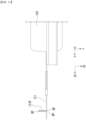
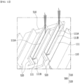
FIGS. 12 and13 together withFIGS. 8 ,10 , and11 , theelectrode lead 111 may be welded and joined to thesecond portion 520 as previously described. Thesecond portion 520 is provided on thebusbar 500, and theelectrode lead 111 does not need to be bent, but the welding process may be difficult compared to theconventional electrode lead 11L in a bent form. As shown inFIG. 3 , in the conventional case, since theelectrode lead 11L is bent, the portion where theelectrode lead 11L and thebusbar 40 are in close contact can be seen from the front, and welding is performed by irradiating the relevant portion with a laser, etc., so that the welding process is relatively simple. On the other hand, since theelectrode lead 111 according to the present embodiment does not have a portion bent at a right angle, the portion where theelectrode lead 111 and thesecond portion 520 are in close contact is not the surface seen from the front, and it may be difficult to irradiate the laser due to an angle. - In order to improve weldability and achieve a stable welding junction between the
electrode lead 111 and thesecond portion 520, according to this embodiment, the above-mentionedbead portion 111B was formed on theelectrode lead 111. - As shown in
FIGS. 12 and13 , the joiningportion 111A, which is a joining portion of theelectrode lead 111 and thesecond portion 520, may be provided at a portion where thebead portion 111B is connected to theelectrode lead 111. Here, the portion where thebead portion 111B is connected to theelectrode lead 111 refers to the starting portion where thebead portion 111B begins to protrude from theelectrode lead 111. That is, the portion where thebead portion 111B is connected to theelectrode lead 111 may be joined to thesecond portion 520 to form a joiningportion 111A. - More specifically, a portion where the
bead portion 111B is connected to theelectrode lead 111 to form a joiningportion 111A can be irradiated with the laser L to form the joiningportion 111A. The joiningportion 111A can be formed by irradiating the laser L while making an angle of about 45 degrees with one surface of thesecond portion 520, through which theelectrode lead 111 and thebusbar 500 can be electrically connected. As previously explained, the portion where theelectrode lead 111 and thesecond portion 520 are in close contact is not a surface that is seen from the front, but since thebead portion 111B is provided and the laser L inclined at a certain angle is irradiated to the portion where thebead portion 111B is connected to theelectrode lead 111, a stable welding process can be achieved. That is, thebead portion 111B according to the present embodiment can be provided so as to improve the welding processability so that theelectrode lead 111 protruding along the second direction d2 can be stably welded and joined to thesecond portion 520. -
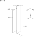
FIG. 14 is a diagram showing an electrode lead of a battery cell according to another embodiment of the present disclosure. - Referring to
FIG. 14 , theelectrode lead 111 according to another embodiment of the present disclosure may have abead portion 111B'. Thebead portion 111B' may protrude from the middle portion of theelectrode lead 111 in a direction different from the second direction d2, for example, in a direction parallel to the first direction d1. This is similar to thebead portion 111B described above. Thebead portion 111B' according to the present embodiment may be formed by attaching a plate-shaped member to the middle portion of theelectrode lead 111. - On the other hand, referring again to
FIGS. 10 and11 , thebead portion 111B according to an embodiment of the present disclosure may be a portion formed by bending theelectrode lead 111 at least three times.FIG. 11 shows a case in which three bending portions BP are formed in theelectrode lead 111 to finally form abead portion 111B. Unlike thebead portion 111B' to which a plate-shaped member is attached, thebead portion 111B according to the present embodiment can be formed by simply bending theelectrode lead 111 multiple times, and thus, it has the advantage that the production method is simple. That is, thebead portions electrode lead 111 in a direction different from the second direction d2, but when considering the convenience of the production method, thebead portion 111B formed by bending theelectrode lead 111 at least three times may be preferable. -
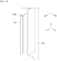
FIG. 15 is a perspective view showing a busbar frame according to an embodiment of the present disclosure. - Referring to
FIGS. 6 and15 together, the battery module according to the present embodiment may further include abusbar frame 600. InFIG. 6 , only thebusbar 500 is shown for convenience of explanation, but thebusbar frame 600 may be located between thebattery cell stack 120 and thebusbar 500. Thebusbar 500 can be mounted on such abusbar frame 600. - Specifically, the
busbars 500 are mounted on one surface of thebusbar frame 600, and thebattery cell stack 120 may be located on the other surface of thebusbar frame 600. The electrode leads 111 of thebattery cell 110 passes through aslit 600S formed in thebusbar frame 600, and can be joined to thebusbar 500. The junction between theelectrode lead 111 and thebusbar 500 has been described previously, and therefore, a description thereof will be omitted. - The
busbar frame 600 may include an electrically insulating material. As one example, thebusbar frame 600 may include a plastic material that is electrically insulating. Thebusbar frame 600 is a member disposed to prevent a short circuit from occurring when a portion of thebattery cells 110 other than theelectrode lead 111 is joined to thebusbar 500. - Although not specifically shown, the
busbar frame 600 may be mounted with a terminal busbar that functions as an external input/output terminal and a sensing assembly that transmits temperature and voltage information of the battery cell. - On the other hand, referring again to
FIG. 4 , thebattery module 100 according to the present embodiment may further include amodule frame 200 in which thebattery cell stack 120 is housed. Themodule frame 200 is a member that houses thebattery cell stack 120 therein, and may include twoside surface portions upper surface portion 230, and alower surface portion 240. Further, themodule frame 200 may have a configuration in which both sides corresponding to the second direction and the opposite direction are open. Thebattery cell stack 120 can be housed through either of the two open sides. Themodule frame 200 may include a metal material having a predetermined strength in order to protect internal electrical components. - The
module frame 200 shown inFIG. 4 may be a mono frame in which twoside surface portions upper surface portion 230, and alower surface portion 240 are integrated. That is, it may be produced by extrusion molding, and can have a configuration in which the twoside surface portions upper surface portion 230, and thelower surface portion 240 are integrated. Although not specifically shown, in another embodiment of the present disclosure, a module frame in which the U-shaped frame and upper plate are welded together is also available. Looking at the stacking direction of themodule frame 200 and thebattery cells 110, thebattery cells 110 may be stacked from oneside surface portion 210 to the otherside surface portion 220 so that one surface of thebattery cells 110 is parallel to one surface of theside surface portions module frame 200. - On the other hand, the
battery module 100 according to the present embodiment may further compriseend plates 300 located on both open sides of themodule frame 200. Theend plates 300 may be located so as to cover thebattery cell stack 120 on both open sides of themodule frame 200. The edges ofrespective end plates 300 may be joined to the corresponding edges of themodule frame 200 by a welding method. Theend plates 300 may include a metal material having a predetermined strength, and may protect thebattery cell stack 120 and other electrical components from external impact. Thebusbar 500 andbusbar frame 600 described above may be located between theend plate 300 and thebattery cell stack 120. - The
battery module 100 may further comprise athermal resin layer 400 located between thebattery cell stack 120 and thelower surface portion 240 of themodule frame 200. One side of thebattery cells 110 may be adhered to thethermal resin layer 400. Specifically, thethermal resin layer 400 may be formed by injecting or applying a thermal resin and then curing it. The thermal resin may include a thermally conductive adhesive material, and specifically may include at least one of a silicone material, a urethane material, or an acrylic material. The thermal resin can be in a liquid phase during application, but can be cured after application to be adhered to one side of thebattery cell 110. Thereby, thethermal resin layer 400 may serve to fix thebattery cells 110. In addition, thethermal resin layer 400 has excellent heat conduction properties, and can quickly transfer heat generated in thebattery cell 110 to the lower side of the battery module. - The terms representing directions such as the front side, the rear side, the left side, the right side, the upper side, and the lower side have been used in the present embodiment, but the terms used are provided simply for convenience of description and may become different according to the position of an object, the position of an observer, or the like.
- The one or more battery modules according to embodiments of the present disclosure described above can be mounted together with various control and protection systems such as a BMS(battery management system), a BDU(battery disconnect unit), and a cooling system to form a battery pack.
- The battery module or the battery pack can be applied to various devices. Specifically, it can be applied to vehicle means such as an electric bike, an electric vehicle, and a hybrid electric vehicle, or an ESS (Energy Storage System), and can be applied to various devices capable of using a secondary battery, without being limited thereto.
- The invention has been described in detail with reference to preferred embodiments thereof. However, it will be appreciated by those skilled in the art that the scope of the present disclosure is not limited thereto, and various modifications and improvements can be made in these embodiment without departing from the principles and sprit of the invention, the scope of which is defined in the appended claims and their equivalents.
-
- 100: battery module
- 110: battery cell
- 111: electrode lead
- 111A: joining portion
- 111B: bead portion
- 120: battery cell stack
- 200: module frame
- 300: end plate
- 400: thermal resin layer
- 500: busbar
- 510: first portion
- 520: second portion
- 600: busbar frame
Claims (14)
- A battery module comprising:a battery cell stack in which battery cells are stacked along a first direction; andat least one busbar located on one side or both sides of the battery cell stack,wherein an electrode lead protrudes from the battery cell along a second direction perpendicular to the first direction,wherein the busbar comprises a first portion, and a second portion that extends from the first portion at a certain angle with one surface of the first portion, andwherein the electrode lead is joined to the second portion.
- The battery module as claimed in claim 1, wherein:the battery cell is a pouch-type battery cell, andin the battery cell stack, the battery cells are stacked in an upright state so that one-side surfaces of the battery cells faces each other.
- The battery module as claimed in claim 1, wherein:
the second portion extends so that one surface of the second portion is perpendicular to one surface of the first portion. - The battery module as claimed in claim 1, wherein:
one surface of the first portion is parallel to the first direction, and one surface of the second portion is parallel to the second direction. - The battery module as claimed in claim 1, wherein:
the electrode lead is welded and joined to the second portion. - The battery module as claimed in claim 1, wherein:the busbar is formed with an open portion, andat least one of the electrode leads is joined to the second portion while passing through the open portion.
- The battery module as claimed in claim 1,further comprising a busbar frame located between the battery cell stack and the busbar, and the busbar is mounted on the busbar frame,wherein the busbar frame is formed with a slit, andwherein the electrode lead passes through the slit and is joined to the second portion of the busbar.
- The battery module as claimed in claim 1, wherein:
the electrode lead is formed with a bead portion protruding in a direction different from the second direction. - The battery module as claimed in claim 8, wherein:
the bead portion protrudes from a middle portion of the electrode lead in a direction parallel to the first direction. - The battery module as claimed in claim 8, wherein:
the bead portion is a portion formed by bending the electrode lead at least three times. - The battery module as claimed in claim 8, wherein:
a joining portion, which is a portion where the electrode lead and the second portion are joined, is provided at a portion where the bead portion is connected to the electrode lead. - The battery module as claimed in claim 11, wherein:
the portion where the bead portion is connected to the electrode lead is irradiated with a laser to form the joining portion. - The battery module as claimed in claim 1,
further comprising a module frame in which the battery cell stack is housed. - A battery pack comprising the battery module as claimed in claim 1.
Applications Claiming Priority (2)
| Application Number | Priority Date | Filing Date | Title |
|---|---|---|---|
| KR1020220167843A KR20240083564A (en) | 2022-12-05 | 2022-12-05 | Battery module and battery pack including the same |
| PCT/KR2023/011803 WO2024122795A1 (en) | 2022-12-05 | 2023-08-10 | Battery module and battery pack including same |
Publications (2)
| Publication Number | Publication Date |
|---|---|
| EP4498501A1 true EP4498501A1 (en) | 2025-01-29 |
| EP4498501A4 EP4498501A4 (en) | 2025-09-17 |
Family
ID=91379529
Family Applications (1)
| Application Number | Title | Priority Date | Filing Date |
|---|---|---|---|
| EP23900817.0A Pending EP4498501A4 (en) | 2022-12-05 | 2023-08-10 | BATTERY MODULE AND BATTERY PACK |
Country Status (6)
| Country | Link |
|---|---|
| US (1) | US20250329888A1 (en) |
| EP (1) | EP4498501A4 (en) |
| JP (1) | JP2025516738A (en) |
| KR (1) | KR20240083564A (en) |
| CN (1) | CN119278541A (en) |
| WO (1) | WO2024122795A1 (en) |
Families Citing this family (1)
| Publication number | Priority date | Publication date | Assignee | Title |
|---|---|---|---|---|
| KR20260014965A (en) * | 2024-07-24 | 2026-02-02 | 주식회사 엘지에너지솔루션 | Busbar, battery module and electronic apparatus |
Family Cites Families (10)
| Publication number | Priority date | Publication date | Assignee | Title |
|---|---|---|---|---|
| KR101747397B1 (en) * | 2013-09-25 | 2017-06-14 | 주식회사 엘지화학 | Battery Module Having Electrode Lead with Damping Structure |
| KR102209773B1 (en) * | 2017-05-29 | 2021-01-28 | 주식회사 엘지화학 | Battery Module |
| KR102256733B1 (en) * | 2017-06-13 | 2021-05-26 | 주식회사 엘지에너지솔루션 | Battery module, battery pack including the same, and energy storage system including the same |
| KR102163656B1 (en) * | 2017-06-27 | 2020-10-08 | 주식회사 엘지화학 | Battery module, battery pack including the same, and vehicle including the same |
| JP7054442B2 (en) * | 2018-03-06 | 2022-04-14 | トヨタ自動車株式会社 | Assembled battery and manufacturing method of assembled battery |
| US11128016B2 (en) * | 2018-09-05 | 2021-09-21 | Ford Global Technologies, Llc | Battery assembly joint with Z-shaped weld bead |
| KR102395228B1 (en) * | 2018-10-10 | 2022-05-04 | 주식회사 엘지에너지솔루션 | Mounting method of busbar frame |
| KR102817987B1 (en) * | 2019-11-20 | 2025-06-12 | 에스케이온 주식회사 | Battery Module |
| KR20220025418A (en) * | 2020-08-24 | 2022-03-03 | 주식회사 엘지에너지솔루션 | Battery module and manufacturing method thereof |
| KR102868409B1 (en) | 2021-06-14 | 2025-10-13 | 삼성디스플레이 주식회사 | Method of manufacturing display device, display device manufactured by the same, and electronic device having the display device |
-
2022
- 2022-12-05 KR KR1020220167843A patent/KR20240083564A/en active Pending
-
2023
- 2023-08-10 WO PCT/KR2023/011803 patent/WO2024122795A1/en not_active Ceased
- 2023-08-10 JP JP2024568099A patent/JP2025516738A/en active Pending
- 2023-08-10 CN CN202380041922.4A patent/CN119278541A/en active Pending
- 2023-08-10 EP EP23900817.0A patent/EP4498501A4/en active Pending
- 2023-08-10 US US18/867,397 patent/US20250329888A1/en active Pending
Also Published As
| Publication number | Publication date |
|---|---|
| EP4498501A4 (en) | 2025-09-17 |
| WO2024122795A1 (en) | 2024-06-13 |
| JP2025516738A (en) | 2025-05-30 |
| CN119278541A (en) | 2025-01-07 |
| KR20240083564A (en) | 2024-06-12 |
| US20250329888A1 (en) | 2025-10-23 |
Similar Documents
| Publication | Publication Date | Title |
|---|---|---|
| EP4210152B1 (en) | Battery module and battery pack including same | |
| JP7596525B2 (en) | Battery module and manufacturing method thereof | |
| JP7434572B2 (en) | Battery module, battery pack including the same, and manufacturing method thereof | |
| EP4435958A1 (en) | Battery module and battery pack including same | |
| CN114467224B (en) | Battery module, battery pack including the battery module, and method of manufacturing the battery module | |
| KR20220120512A (en) | Battery module and manufacturing method of the same | |
| JP7546678B2 (en) | Battery module, battery pack including same, and method of manufacturing same | |
| US20250329888A1 (en) | Battery module and battery pack including the same | |
| JP7662271B2 (en) | Battery module and battery pack including same | |
| EP4181286B1 (en) | BATTERY MODULE AND BATTERY BLOCK INCLUDING IT | |
| CN218919099U (en) | Battery module and battery pack | |
| US20260045647A1 (en) | Battery Cell and Battery Module Including the Same | |
| CN216872164U (en) | Battery unit, battery module, and vehicle | |
| EP4607672A1 (en) | Battery module and battery pack including same | |
| KR20240097773A (en) | Battery cell and battery module including the same | |
| JP2025537982A (en) | Battery module and battery pack including same |
Legal Events
| Date | Code | Title | Description |
|---|---|---|---|
| STAA | Information on the status of an ep patent application or granted ep patent |
Free format text: STATUS: THE INTERNATIONAL PUBLICATION HAS BEEN MADE |
|
| PUAI | Public reference made under article 153(3) epc to a published international application that has entered the european phase |
Free format text: ORIGINAL CODE: 0009012 |
|
| STAA | Information on the status of an ep patent application or granted ep patent |
Free format text: STATUS: REQUEST FOR EXAMINATION WAS MADE |
|
| 17P | Request for examination filed |
Effective date: 20241023 |
|
| AK | Designated contracting states |
Kind code of ref document: A1 Designated state(s): AL AT BE BG CH CY CZ DE DK EE ES FI FR GB GR HR HU IE IS IT LI LT LU LV MC ME MK MT NL NO PL PT RO RS SE SI SK SM TR |
|
| A4 | Supplementary search report drawn up and despatched |
Effective date: 20250819 |
|
| RIC1 | Information provided on ipc code assigned before grant |
Ipc: H01M 50/503 20210101AFI20250812BHEP Ipc: H01M 50/533 20210101ALI20250812BHEP Ipc: H01M 50/211 20210101ALI20250812BHEP Ipc: H01M 50/105 20210101ALI20250812BHEP |
|
| DAV | Request for validation of the european patent (deleted) | ||
| DAX | Request for extension of the european patent (deleted) |