EP4498496A1 - Battery pack - Google Patents
Battery pack Download PDFInfo
- Publication number
- EP4498496A1 EP4498496A1 EP23774333.1A EP23774333A EP4498496A1 EP 4498496 A1 EP4498496 A1 EP 4498496A1 EP 23774333 A EP23774333 A EP 23774333A EP 4498496 A1 EP4498496 A1 EP 4498496A1
- Authority
- EP
- European Patent Office
- Prior art keywords
- case
- protrusion
- engagement mechanism
- housing
- battery pack
- Prior art date
- Legal status (The legal status is an assumption and is not a legal conclusion. Google has not performed a legal analysis and makes no representation as to the accuracy of the status listed.)
- Pending
Links
Images








Classifications
-
- H—ELECTRICITY
- H01—ELECTRIC ELEMENTS
- H01M—PROCESSES OR MEANS, e.g. BATTERIES, FOR THE DIRECT CONVERSION OF CHEMICAL ENERGY INTO ELECTRICAL ENERGY
- H01M50/00—Constructional details or processes of manufacture of the non-active parts of electrochemical cells other than fuel cells, e.g. hybrid cells
- H01M50/20—Mountings; Secondary casings or frames; Racks, modules or packs; Suspension devices; Shock absorbers; Transport or carrying devices; Holders
- H01M50/262—Mountings; Secondary casings or frames; Racks, modules or packs; Suspension devices; Shock absorbers; Transport or carrying devices; Holders with fastening means, e.g. locks
-
- H—ELECTRICITY
- H01—ELECTRIC ELEMENTS
- H01M—PROCESSES OR MEANS, e.g. BATTERIES, FOR THE DIRECT CONVERSION OF CHEMICAL ENERGY INTO ELECTRICAL ENERGY
- H01M50/00—Constructional details or processes of manufacture of the non-active parts of electrochemical cells other than fuel cells, e.g. hybrid cells
- H01M50/20—Mountings; Secondary casings or frames; Racks, modules or packs; Suspension devices; Shock absorbers; Transport or carrying devices; Holders
- H01M50/204—Racks, modules or packs for multiple batteries or multiple cells
-
- H—ELECTRICITY
- H01—ELECTRIC ELEMENTS
- H01M—PROCESSES OR MEANS, e.g. BATTERIES, FOR THE DIRECT CONVERSION OF CHEMICAL ENERGY INTO ELECTRICAL ENERGY
- H01M50/00—Constructional details or processes of manufacture of the non-active parts of electrochemical cells other than fuel cells, e.g. hybrid cells
- H01M50/20—Mountings; Secondary casings or frames; Racks, modules or packs; Suspension devices; Shock absorbers; Transport or carrying devices; Holders
- H01M50/204—Racks, modules or packs for multiple batteries or multiple cells
- H01M50/207—Racks, modules or packs for multiple batteries or multiple cells characterised by their shape
- H01M50/213—Racks, modules or packs for multiple batteries or multiple cells characterised by their shape adapted for cells having curved cross-section, e.g. round or elliptic
-
- H—ELECTRICITY
- H01—ELECTRIC ELEMENTS
- H01M—PROCESSES OR MEANS, e.g. BATTERIES, FOR THE DIRECT CONVERSION OF CHEMICAL ENERGY INTO ELECTRICAL ENERGY
- H01M50/00—Constructional details or processes of manufacture of the non-active parts of electrochemical cells other than fuel cells, e.g. hybrid cells
- H01M50/20—Mountings; Secondary casings or frames; Racks, modules or packs; Suspension devices; Shock absorbers; Transport or carrying devices; Holders
- H01M50/233—Mountings; Secondary casings or frames; Racks, modules or packs; Suspension devices; Shock absorbers; Transport or carrying devices; Holders characterised by physical properties of casings or racks, e.g. dimensions
- H01M50/242—Mountings; Secondary casings or frames; Racks, modules or packs; Suspension devices; Shock absorbers; Transport or carrying devices; Holders characterised by physical properties of casings or racks, e.g. dimensions adapted for protecting batteries against vibrations, collision impact or swelling
-
- H—ELECTRICITY
- H01—ELECTRIC ELEMENTS
- H01M—PROCESSES OR MEANS, e.g. BATTERIES, FOR THE DIRECT CONVERSION OF CHEMICAL ENERGY INTO ELECTRICAL ENERGY
- H01M50/00—Constructional details or processes of manufacture of the non-active parts of electrochemical cells other than fuel cells, e.g. hybrid cells
- H01M50/20—Mountings; Secondary casings or frames; Racks, modules or packs; Suspension devices; Shock absorbers; Transport or carrying devices; Holders
- H01M50/271—Lids or covers for the racks or secondary casings
-
- H—ELECTRICITY
- H01—ELECTRIC ELEMENTS
- H01M—PROCESSES OR MEANS, e.g. BATTERIES, FOR THE DIRECT CONVERSION OF CHEMICAL ENERGY INTO ELECTRICAL ENERGY
- H01M50/00—Constructional details or processes of manufacture of the non-active parts of electrochemical cells other than fuel cells, e.g. hybrid cells
- H01M50/20—Mountings; Secondary casings or frames; Racks, modules or packs; Suspension devices; Shock absorbers; Transport or carrying devices; Holders
- H01M50/289—Mountings; Secondary casings or frames; Racks, modules or packs; Suspension devices; Shock absorbers; Transport or carrying devices; Holders characterised by spacing elements or positioning means within frames, racks or packs
- H01M50/291—Mountings; Secondary casings or frames; Racks, modules or packs; Suspension devices; Shock absorbers; Transport or carrying devices; Holders characterised by spacing elements or positioning means within frames, racks or packs characterised by their shape
-
- H—ELECTRICITY
- H01—ELECTRIC ELEMENTS
- H01M—PROCESSES OR MEANS, e.g. BATTERIES, FOR THE DIRECT CONVERSION OF CHEMICAL ENERGY INTO ELECTRICAL ENERGY
- H01M50/00—Constructional details or processes of manufacture of the non-active parts of electrochemical cells other than fuel cells, e.g. hybrid cells
- H01M50/20—Mountings; Secondary casings or frames; Racks, modules or packs; Suspension devices; Shock absorbers; Transport or carrying devices; Holders
- H01M50/218—Mountings; Secondary casings or frames; Racks, modules or packs; Suspension devices; Shock absorbers; Transport or carrying devices; Holders characterised by the material
- H01M50/22—Mountings; Secondary casings or frames; Racks, modules or packs; Suspension devices; Shock absorbers; Transport or carrying devices; Holders characterised by the material of the casings or racks
- H01M50/227—Organic material
-
- Y—GENERAL TAGGING OF NEW TECHNOLOGICAL DEVELOPMENTS; GENERAL TAGGING OF CROSS-SECTIONAL TECHNOLOGIES SPANNING OVER SEVERAL SECTIONS OF THE IPC; TECHNICAL SUBJECTS COVERED BY FORMER USPC CROSS-REFERENCE ART COLLECTIONS [XRACs] AND DIGESTS
- Y02—TECHNOLOGIES OR APPLICATIONS FOR MITIGATION OR ADAPTATION AGAINST CLIMATE CHANGE
- Y02E—REDUCTION OF GREENHOUSE GAS [GHG] EMISSIONS, RELATED TO ENERGY GENERATION, TRANSMISSION OR DISTRIBUTION
- Y02E60/00—Enabling technologies; Technologies with a potential or indirect contribution to GHG emissions mitigation
- Y02E60/10—Energy storage using batteries
Definitions
- the present disclosure relates to a battery pack.
- a battery pack in which a large number of secondary battery cells are connected in series and in parallel is used as a power source for a portable electric device such as an electric cleaner or an electric power tool, or as a backup power source for a server or a power source device for home use, business use, or factory use for stationary storage, and is further used as a power source for driving an assist bicycle, an electric scooter, an electric cart, a power source for driving a vehicle such as a hybrid vehicle or an electric vehicle, or the like.
- This kind of battery pack has a structure in which a core block holding a plurality of secondary battery cells is housed in an exterior case constituting an outer shape of the battery pack in many cases (e.g., PTL 1).
- the exterior case is generally binary-divided up and down, or right and left.
- the exterior case divided into two divided cases as described above includes one case provided with a claw structure, and the other case provided with a hole for locking the claw, and the divided cases are fitted by fitting of the claw and the hole.
- a battery pack includes: one or more secondary battery cells; and a housing forming a housing space for housing the one or more secondary battery cells.
- the housing is divided into a first case and a second case.
- the first case and the second case are joined at a position where the first case and the second case overlap each other, and include at the position: a first engagement mechanism in which the first case includes a first protrusion protruding in a first direction at a part of an end edge of the first case, and the second case includes a second recess formed at a position corresponding to the first protrusion in a part of an end edge of the second case when the second case is joined to the first case; and a second engagement mechanism in which the first case includes a first recess provided at a position separated from the first protrusion in another part of the end edge of the first case, and the second case includes a second protrusion formed at a position separated from the second recess in another part of the end edge of the second case, the position corresponding to the
- the battery pack according to the aspect of the present disclosure acquires an advantage in that the housing divided into the first case and the second case includes the first protrusion and the second protrusion provided in the first case and the second case, respectively, while protruding the first protrusion and the second protrusion in directions opposite to each other, so that even when one protrusion is deformed in a direction in which the protrusion is disengaged when stress is applied to the battery pack to deform the battery pack, the other protrusion acts in a direction in which the protrusion is engaged, thereby resulting in reducing possibility that the protrusion is disengaged due to external force.
- a power source device in another aspect of the present disclosure in the above aspect is configured such that the second case includes an external wall constituting a surface of the housing, and an internal wall separated from the external wall in the housing space, and the second protrusion protrudes into an insertion space defined by the external wall and the internal wall, and the internal wall being provided with the second recess.
- the above configuration allows a double wall structure to be formed inside the housing to fabricate an engagement mechanism using the protrusions protruding in respective directions opposite to each other.
- a power source device in any one of the above aspects is configured such that the internal wall is partially provided along an inner surface of the external wall.
- a power source device in any one of the above aspects is configured such that the first case includes an intermediate wall inserted between the external wall and the internal wall, and the intermediate wall is provided with the first protrusion and the second recess.
- the above configuration allows the intermediate wall to be sandwiched between the internal wall and the external wall while providing the first engagement mechanism and the second engagement mechanism of the first case and the second case in an interface between the intermediate wall and the internal wall, so that deformation of the intermediate wall can be suppressed to stabilize the engagement.
- a power source device in any one of the above aspects is configured such that the housing is formed in a square shape in plan view, and the first engagement mechanism and the second engagement mechanism are provided on at least one of opposing sides of the square shape.
- the above configuration enables the first case and the second case to be stably connected by providing the engagement mechanism on at least one of a pair of sides forming the square shape.
- a power source device in any one of the above aspects is configured such that the housing is formed in a rectangular shape in plan view, and the first engagement mechanism and the second engagement mechanism are provided on at least one of long sides of the rectangular shape.
- a power source device in any one of the above aspects is configured such that the first engagement mechanism and the second engagement mechanism are provided on one of long sides of the rectangle of the housing, and any one of the first engagement mechanism and the second engagement mechanism is provided on the other of the long sides of the rectangle of the housing.
- a power source device in any one of the above aspects is configured such that the first protrusion or the second protrusion is formed in a claw shape, and the second recess or the first recess is formed in a hole shape to be engaged with the first protrusion or the second protrusion in the claw shape.
- a battery pack of the present disclosure is available as a power source for a portable electric device such as an electric cleaner or an electric power tool, or as a backup power source for a server or a power source device for home use, business use, or factory use for stationary storage, and is further used as a power source for driving an assist bicycle, an electric scooter, an electric cart, a power source for driving a vehicle such as a hybrid vehicle or an electric vehicle, or the like.
- a battery pack used as a power source for a portable electric device will be described as an exemplary embodiment of the present disclosure.
- FIG. 1 is an external perspective view illustrating battery pack 100 according to an exemplary embodiment of the present disclosure
- Fig. 2 is an exploded perspective view of battery pack 100 of Fig. 1
- Fig. 3 is an exploded perspective view of battery pack 100 of Fig. 1 as viewed from behind.
- Battery pack 100 illustrated in these drawings includes one or more secondary battery cells 1 and housing 2.
- Housing 2 has an outer shape of the shape of a box, and is internally provided with housing space 3 for housing secondary battery cells 1, a circuit board, and the like.
- the examples of Figs. 1 and 2 include housing 2 formed in a flat plate shape having an R-shaped front edge.
- the housing is not limited to this shape in the present disclosure, and may have any shape.
- each secondary battery cell 1 is a cylindrical secondary battery cell with an exterior can in a cylindrical shape.
- Housing 2 includes curved surface 4 formed along a cylindrical exterior can for disposing each secondary battery cell 1.
- two rows of four secondary battery cells 1, i.e., a total of eight secondary battery cells 1 are housed in housing 2.
- These secondary battery cells 1 are connected in series or in parallel with a lead plate or the like.
- the secondary battery cells are appropriately determined on shape and number according to specifications required for the battery pack.
- a secondary battery cell called a prismatic battery, a laminate type, a pouch type, or the like may be used.
- a battery holder that holds the secondary battery cell may be separately provided. In this case, the battery holder is housed in housing space 3 in housing 2.
- Secondary battery cell 1 in a cylindrical shape includes opposite end surfaces serving as terminal surfaces.
- One of the terminal surfaces is provided with a safety valve.
- the safety valve is a member configured to open to release internal gas when internal pressure of the exterior can increases.
- the safety valve is typically provided on a positive electrode side, the present disclosure does not specify the positive electrode side as a position where the safety valve is provided. Thus, the safety valve may be provided at another position, such as that on a negative electrode side.
- a lithium ion secondary battery in a cylindrical shape can be suitably used.
- the battery pack of the present disclosure does not specify not only a cylindrical battery but also a lithium ion secondary battery as the secondary battery cell.
- the secondary battery cell all chargeable batteries, such as a nickel-metal hydride battery and a nickel-cadmium battery, can also be used.
- housing 2 is divided into first case 10 and second case 20.
- First case 10 includes top surface 11 and first wall part 12 continuous from around top surface 11.
- Second case 20 includes bottom surface 21 and external wall 22 continuous from around bottom surface 21.
- Second case 20 is formed as a low height type in which external wall 22 is lower than first wall part 12.
- Housing 2 described above is made of a material having insulating properties and flexibility, preferably made of resin. Specifically, polycarbonate, ABC resin, and the like can be suitably used.
- First case 10 and second case 20 are engaged by engagement mechanisms.
- the engagement mechanisms are provided at a plurality of positions where first case 10 and second case 20 overlap each other when first case 10 and second case 20 are joined.
- the examples of Figs. 2 and 3 each show housing 2 in a rectangular shape in plan view, and the engagement mechanisms that are provided on a pair of long sides and a pair of short sides, which constitute the rectangle, for engagement.
- the engagement mechanisms for engaging first case 10 and second case 20 may be common in structure or may be different in structure for each part or each side.
- first engagement mechanism 30 and second engagement mechanism 40 are prepared as the engagement mechanisms.
- first engagement mechanism 30 and second engagement mechanism 40 are illustrated in Figs. 4 to 10 . These drawings include: Fig.
- FIG. 4 that is a sectional perspective view taken along line IV-IV in Fig. 2 ;
- Fig. 5 that is a perspective view of battery pack 100 of Fig. 1 as viewed from behind;
- Fig. 6 that is an exploded perspective view of battery pack 100 of Fig. 5 ;
- Fig. 7 that is a sectional perspective view taken along line VII-VII in Fig. 3 ;
- Fig. 8 that is a sectional view with an enlarged view of a main part taken along line VIII-VIII in Fig. 1 ;
- Fig. 9 that is a sectional perspective view with an enlarged view of a main part taken along line VIII-VIII in Fig. 1 ;
- Fig. 10 that is an exploded perspective view of battery pack 100 of Fig. 9 .
- Subsequent drawings illustrate no secondary battery cell appropriately to enhance visibility in the housing.
- housing 2 is formed by engagement using first engagement mechanism 30 and second engagement mechanism 40 on one side of a pair of long sides constituting a rectangle of housing 2 in plan view, the one side being on a back side.
- second engagement mechanism 40 a part of external wall 22 of second case 20 is cut in the perspective views of Figs. 5 and 6 .
- a front side is engaged using first engagement mechanism 30 as illustrated in Fig. 7 .
- the pair of short sides is engaged using first engagement mechanism 30.
- the long side and the short side on the front side may be engaged using second engagement mechanism 40 instead of first engagement mechanism 30. Details will be described below.
- First engagement mechanism 30 is illustrated in Figs. 11 to 13 .
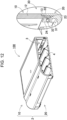
- These drawings include: Fig. 11 that is a sectional view taken along line XI-XI in Fig. 1 with an enlarged view of a main part; Fig. 12 that is a sectional perspective view taken along line XI-XI in Fig. 1 ; and Fig. 13 that is an exploded perspective view of battery pack 100 in Fig. 12 .
- First engagement mechanism 30 illustrated in these drawings includes first protrusion 31 of first case 10 and second recess 32 of second case 20. First protrusion 31 is provided in a part of an end edge of first case 10 and protrudes in first direction DA.
- first direction DA indicates a direction toward housing space 3 of housing 2 perpendicularly from first wall part 12 and external wall 22 as illustrated in Fig. 11 .
- Second recess 32 is a part of an end edge of second case 20, and is formed at a position corresponding to first protrusion 31 when second case 20 is joined to first case 10.
- First protrusion 31 is formed in a claw shape.
- Second recess 32 is formed in a hole shape to be engaged with first protrusion 31 in a claw shape.
- First engagement mechanism 30 including first protrusion 31 and second recess 32 described above is also used for another side other than the long side on the back side constituting the rectangle of housing 2 in plan view. That is, first protrusions 31 are formed at a plurality of positions separated from each other on intermediate wall 13 of first case 10, and second recesses 32 are formed at a plurality of positions separated from each other on internal wall 24 of second case 20, also on the long side on the front side as illustrated in Figs. 7 , 16 , and 17 , and the like, and thus fitting first case 10 to second case 20 by engaging first protrusions 31 with corresponding second recesses 32.
- first protrusions 31 are formed at a plurality of positions separated from each other on intermediate wall 13 of first case 10
- second recesses 32 are formed at a plurality of positions separated from each other on internal wall 24 of second case 20, also on the short side as illustrated in Figs. 8 , 9 , and 10 , and thus fitting first case 10 to second case 20 by engaging first protrusions 31 with corresponding second recesses 32.
- FIG. 14 that is a sectional view with an enlarged view of a main part taken along line XIV-XIV in Fig. 1 ;
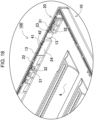
- Fig. 15 that is a sectional perspective view taken along line XIV-XIV in Fig. 1 ;
- Fig. 16 that is an exploded perspective view of battery pack 100 of Fig. 15 ;
- Fig. 17 that is an enlarged perspective view of a main part of Fig. 6 ;
- Fig. 18 that is a horizontal sectional view of battery pack 100 of Fig. 1 , taken along line XVIII-XVIII.
- Second engagement mechanism 40 illustrated in these drawings includes first recess 42 of first case 10 and second protrusion 41 of second case 20.
- First recess 42 is another part of the end edge of first case 10 and is provided at a position separated from first protrusion 31.
- Second protrusion 41 is another part of the end edge of second case 20, and is formed at a position separated from second recess 32 and at a position corresponding to first recess 42 when second case 20 is joined to first case 10.
- Second protrusion 41 is caused to protrude in second direction DB.
- Second direction DB is opposite to first direction DA, i.e., is perpendicular to external wall 22 from housing space 3 of housing 2.
- Second protrusion 41 is formed in a claw shape.
- First recess 42 is formed in a hole shape to be engaged with second protrusion 41 in a claw shape. As described above, when the engagement mechanisms protruding in respective directions different from each other are provided side by side on one surface of housing 2 to engage first case 10 with second case 20, stable connection strength against deformation can be exhibited.
- housing 900 as described above needs to increase connection strength between divided upper case 910 and lower case 920.
- stable connection strength against deformation is required to prevent housing 900 from being disassembled by impact at the time of falling.
- a housing for a battery pack is preferably increased in resistance of connection against deformation.
- a secondary battery cell is configured to open a safety valve to release internal gas when internal pressure of an exterior can becomes high due to an abnormality or the like.
- a housing space of the housing may be caused to have a high pressure.
- a fitting structure generally has a problem of being weak against deformation in a specific direction due to engagement using elastic deformation. For example, when stress is applied from inside (from right to left in Fig. 23 ) in a locking structure using claw fitting in which claw 931 is locked to locking piece 932 as illustrated in Fig. 23 , claw 931 is deformed in a direction of being disengaged from locking piece 932 as illustrated in Fig. 24 , and thus the engagement is likely to be released.
- first engagement mechanism 30 illustrated in the enlarged sectional view of Fig. 11 includes first protrusion 31 that is provided on first case 10 and caused to protrude toward an inner surface of housing 2.
- This structure allows first protrusion 31 to be deformed in a direction in which first protrusion 31 tends to engage into second recess 32 more deeply when stress is applied in a direction in which first case 10 and second case 20 are deformed into a dogleg shape as illustrated in Fig. 19 , so that first protrusion 31 acts in a direction forming strong engagement.
- first case 10 and second case 20 are conversely deformed in a chevron shape as illustrated in Fig. 20
- first protrusion 31 is deformed in a direction of releasing engagement of first protrusion 31.
- second engagement mechanism 40 illustrated in Fig. 14 includes second protrusion 41 that is provided on second case 20 and is caused to protrude in a direction toward outside housing 2 contrary to first engagement mechanism 30.
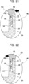
- This structure allows second protrusion 41 to be deformed in a direction in which second protrusion 41 tends to engage into first recess 42 more deeply when stress is applied in a direction in which first case 10 and second case 20 are deformed into a chevron shape as illustrated in Fig. 21 , so that second protrusion 41 acts in a direction forming strong engagement. That is, second engagement mechanism 40 provided at a different position exerts a strong engaging force as illustrated in Fig. 21 even for the deformation illustrated in Fig. 20 , so that connection between first case 10 and second case 20 can be maintained.
- first engagement mechanism 30 acts in a direction of enhancing engagement in this case as illustrated in Fig. 19 , so that the connection between first case 10 and second case 20 can be maintained by first engagement mechanism 30 that is also similarly provided at a different position.
- any one of the engagement mechanisms can maintains engagement even with the one surface deformed in any direction, and thus reliability of the engagement can be enhanced.
- first engagement mechanism 30 is likely to be deformed into a chevron shape as illustrated in Figs. 20 and 21 .
- engagement of second engagement mechanism 40 is likely to be strengthened while engagement of first engagement mechanism is likely to be weakened, so that joining can be maintained.
- first case 10 and second case 20 when stress is applied to the joint interface between first case 10 and second case 20 from outside housing 2, the joint interface is likely to be deformed into a dogleg shape as illustrated in Figs. 19 and 22 . Then, the engagement of second engagement mechanism 40 is likely to be weakened while joining of first engagement mechanism 30 is likely to be strengthened, so that the joining can be similarly maintained.
- second case 20 includes internal wall 24 added to an inner surface of external wall 22.
- Internal wall 24 is formed apart from external wall 22 in housing space 3.
- insertion space 23 can be formed between external wall 22 and internal wall 24.
- a double wall structure is formed inside housing 2 to fabricate an engagement mechanism using the protrusions protruding in respective directions opposite to each other.
- Internal wall 24 is also provided with second recess 32. Then, second protrusion 41 of second case 20 is caused to protrude into insertion space 23.
- Internal wall 24 may not be provided along the entire circumference of external wall 22.
- Fig. 4 shows an example in which internal wall 24 located on the long side of the square shape is partially provided along an inner surface of external wall 22 on the back side.
- internal wall 24 on the front side on the long side and internal wall 24 on the short side are each formed along external wall 22 as illustrated in Figs. 2 , 3 , and 5 .
- a small piece provided with only first engagement mechanism 30 is provided with external wall 22 and internal wall 24.
- a small piece provided with first engagement mechanism 30 and second engagement mechanism 40 is provided with internal wall 24 in a discontinuous manner.
- a plurality of second engagement mechanisms may be provided.
- the plurality of second engagement mechanisms may be provided apart from each other on the long side on the back side, the long side constituting the square shape of housing 2 in plan view.
- the second engagement mechanism may also be provided on the long side or the short side on the front side.
- Internal wall 24 is provided with second protrusion 41 and second recess 32 at respective positions separated from each other.
- second protrusion 41 and second recess 32 are provided apart from each other in internal wall 24 common to them as illustrated in Figs. 17 and 18 , first engagement mechanism 30 and second engagement mechanism 40 are brought close to each other to some extent to maintain a joining force.
- First case 10 is also provided with intermediate wall 13.
- Intermediate wall 13 is inserted into insertion space 23 between external wall 22 and internal wall 24.
- Fig. 18 illustrates a part of intermediate wall 13 of first case 10 in gray for the sake of description.
- Intermediate wall 13 is provided with first protrusion 31 and first recess 42. This configuration allows intermediate wall 13 to be sandwiched between internal wall 24 and external wall 22 while providing first engagement mechanism 30 and second engagement mechanism 40 of first case 10 and second case 20 in an interface between intermediate wall 13 and internal wall 24, so that deformation of intermediate wall 13 can be suppressed to stabilize engagement.
- first engagement mechanism 30 and second engagement mechanism 40 are provided on one side of the pair of long sides constituting the rectangle, the one side being on the back side.
- first engagement mechanism 30 is provided at thirteen locations, while second engagement mechanism 40 is provided at one location.
- First engagement mechanisms 30 are provided on both sides of second engagement mechanism 40.
- first engagement mechanism 30 As illustrated in Fig. 7 , intermediate wall 13 is caused to protrude from an end surface of first case 10, and first protrusion 31 is formed apart from an inner surface of intermediate wall 13.
- internal wall 24 is divided by recess 14 formed in the middle. A part of internal wall 24 divided is provided with a plurality of first protrusions 31.
- first engagement mechanism 30 and second engagement mechanism 40 which are disposed protruding in respective directions opposite to each other, are combined as an engagement mechanism of housing 2 divided into first case 10 and second case 20, a connection structure can be fabricated in which first case 10 and second case 20 are less likely to be disengaged against deformation caused by impact or the like.
- the present disclosure can be suitably used in applications such as a battery pack required to address not only an impact from outside due to falling or the like but also a stress from inside, the stress being caused when secondary battery cell 1 stored in housing space 3 has a high pressure at the time of abnormality.
- the battery pack according to the present disclosure can be suitably used as a power source of a portable electric device such as an electric cleaner or an electric tool, and a housing of the power source.
- a portable electric device such as an electric cleaner or an electric tool
- the present disclosure also can be appropriately used for applications such as a power source device for a moving body such as an assist bicycle or an electric cart.
Landscapes
- Chemical & Material Sciences (AREA)
- Chemical Kinetics & Catalysis (AREA)
- Electrochemistry (AREA)
- General Chemical & Material Sciences (AREA)
- Battery Mounting, Suspending (AREA)
Abstract
Description
- The present disclosure relates to a battery pack.
- A battery pack in which a large number of secondary battery cells are connected in series and in parallel is used as a power source for a portable electric device such as an electric cleaner or an electric power tool, or as a backup power source for a server or a power source device for home use, business use, or factory use for stationary storage, and is further used as a power source for driving an assist bicycle, an electric scooter, an electric cart, a power source for driving a vehicle such as a hybrid vehicle or an electric vehicle, or the like. This kind of battery pack has a structure in which a core block holding a plurality of secondary battery cells is housed in an exterior case constituting an outer shape of the battery pack in many cases (e.g., PTL 1).
- The exterior case is generally binary-divided up and down, or right and left. The exterior case divided into two divided cases as described above includes one case provided with a claw structure, and the other case provided with a hole for locking the claw, and the divided cases are fitted by fitting of the claw and the hole.
- Unfortunately, there is a problem that the claw fitting is likely to be disengaged when a wall is deformed outward due to an increase in internal pressure of the battery pack.
- PTL 1: Unexamined
Japanese Patent Publication No. 2003-123715 - It is an object of the present disclosure to provide a battery pack in which fitting of a claw is less likely to be disengaged.
- A battery pack according to an aspect of the present disclosure includes: one or more secondary battery cells; and a housing forming a housing space for housing the one or more secondary battery cells. The housing is divided into a first case and a second case. The first case and the second case are joined at a position where the first case and the second case overlap each other, and include at the position: a first engagement mechanism in which the first case includes a first protrusion protruding in a first direction at a part of an end edge of the first case, and the second case includes a second recess formed at a position corresponding to the first protrusion in a part of an end edge of the second case when the second case is joined to the first case; and a second engagement mechanism in which the first case includes a first recess provided at a position separated from the first protrusion in another part of the end edge of the first case, and the second case includes a second protrusion formed at a position separated from the second recess in another part of the end edge of the second case, the position corresponding to the first recess when the second case is joined to the first case, and the second protrusion protruding in a second direction opposite the first direction.
- The battery pack according to the aspect of the present disclosure acquires an advantage in that the housing divided into the first case and the second case includes the first protrusion and the second protrusion provided in the first case and the second case, respectively, while protruding the first protrusion and the second protrusion in directions opposite to each other, so that even when one protrusion is deformed in a direction in which the protrusion is disengaged when stress is applied to the battery pack to deform the battery pack, the other protrusion acts in a direction in which the protrusion is engaged, thereby resulting in reducing possibility that the protrusion is disengaged due to external force.
-
-
Fig. 1 is an external perspective view illustrating a battery pack according to an exemplary embodiment of the present disclosure. -
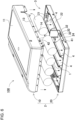
Fig. 2 is an exploded perspective view of the battery pack ofFig. 1 . -
Fig. 3 is an exploded perspective view of the battery pack ofFig. 1 as viewed from behind. -
Fig. 4 is a sectional perspective view taken along line IV-IV inFig. 2 . -
Fig. 5 is a perspective view of the battery pack ofFig. 1 as viewed from behind, in which a part of an external wall is cut. -
Fig. 6 is an exploded perspective view of the battery pack ofFig. 5 . -
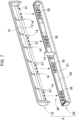
Fig. 7 is a sectional perspective view taken along line VII-VII inFig. 3 . -
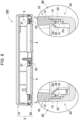
Fig. 8 is a sectional view with an enlarged view of a main part taken along line VIII-VIII inFig. 1 . -
Fig. 9 is a sectional perspective view with an enlarged view of a main part taken along line VIII-VIII inFig. 1 . -
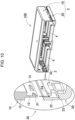
Fig. 10 is an exploded perspective view of the battery pack ofFig. 9 . -
Fig. 11 is a sectional view with an enlarged view of a main part taken along line XI-XI inFig. 1 . -
Fig. 12 is a sectional perspective view taken along line XI-XI inFig. 1 . -
Fig. 13 is an exploded perspective view of the battery pack ofFig. 12 . -
Fig. 14 is a sectional view with an enlarged view of a main part taken along line XIV-XIV inFig. 1 . -
Fig. 15 is a sectional perspective view taken along line XIV-XIV inFig. 1 . -
Fig. 16 is an exploded perspective view of the battery pack ofFig. 15 . -
Fig. 17 is an enlarged perspective view of a main part ofFig. 6 . -
Fig. 18 is a horizontal sectional view taken along line XVIII-XVIII of the battery pack ofFig. 1 . -
Fig. 19 is a sectional view illustrating a state in which stress for deforming a first case and a second case into a dogleg shape is applied inFig. 11 . -
Fig. 20 is a sectional view illustrating a state in which stress for deforming a first case and a second case into a dogleg shape is applied inFig. 11 . -
Fig. 21 is a sectional view illustrating a state in which stress for deforming a first case and a second case into a dogleg shape is applied inFig. 14 . -
Fig. 22 is a sectional view illustrating a state in which stress for deforming a first case and a second case into a dogleg shape is applied inFig. 14 . -
Fig. 23 is a sectional view illustrating a fitting structure of a battery pack according to a comparative example. -
Fig. 24 is a sectional view illustrating a state in which the fitting structure of the battery pack ofFig. 23 is loosened. - Exemplary embodiments of the present disclosure may be specified by the following configurations and features.
- A power source device according to another aspect of the present disclosure in the above aspect is configured such that the second case includes an external wall constituting a surface of the housing, and an internal wall separated from the external wall in the housing space, and the second protrusion protrudes into an insertion space defined by the external wall and the internal wall, and the internal wall being provided with the second recess. The above configuration allows a double wall structure to be formed inside the housing to fabricate an engagement mechanism using the protrusions protruding in respective directions opposite to each other.
- A power source device according to another aspect of the present disclosure in any one of the above aspects is configured such that the internal wall is partially provided along an inner surface of the external wall.
- A power source device according to still another aspect of the present disclosure in any one of the above aspects is configured such that the first case includes an intermediate wall inserted between the external wall and the internal wall, and the intermediate wall is provided with the first protrusion and the second recess. The above configuration allows the intermediate wall to be sandwiched between the internal wall and the external wall while providing the first engagement mechanism and the second engagement mechanism of the first case and the second case in an interface between the intermediate wall and the internal wall, so that deformation of the intermediate wall can be suppressed to stabilize the engagement.
- A power source device according to still another aspect of the present disclosure in any one of the above aspects is configured such that the housing is formed in a square shape in plan view, and the first engagement mechanism and the second engagement mechanism are provided on at least one of opposing sides of the square shape. The above configuration enables the first case and the second case to be stably connected by providing the engagement mechanism on at least one of a pair of sides forming the square shape.
- A power source device according to still another aspect of the present disclosure in any one of the above aspects is configured such that the housing is formed in a rectangular shape in plan view, and the first engagement mechanism and the second engagement mechanism are provided on at least one of long sides of the rectangular shape.
- A power source device according to still another aspect of the present disclosure in any one of the above aspects is configured such that the first engagement mechanism and the second engagement mechanism are provided on one of long sides of the rectangle of the housing, and any one of the first engagement mechanism and the second engagement mechanism is provided on the other of the long sides of the rectangle of the housing.
- A power source device according to still another aspect of the present disclosure in any one of the above aspects is configured such that the first protrusion or the second protrusion is formed in a claw shape, and the second recess or the first recess is formed in a hole shape to be engaged with the first protrusion or the second protrusion in the claw shape.
- Exemplary embodiments of the present disclosure are described below with reference to the drawings. However, the exemplary embodiments described below are examples for embodying the technical idea of the present disclosure, and the present disclosure is not limited to the exemplary embodiments described below. The present specification does not certainly specify members indicated in the scope of claims to the members of the exemplary embodiments. In particular, the dimensions, materials, shapes, relative arrangements, and the like of the components described in the exemplary embodiment are not intended to limit the scope of the present disclosure exclusively unless otherwise specified, and are merely illustrative examples. Members shown in each drawing have sizes, positional relationships, or the like that may be exaggerated for clarity of description. The same names and reference numerals in the following description indicate the same or similar members, and detailed description thereof will not be appropriately described. Each element constituting the present disclosure may be configured such that a plurality of elements is formed of one member to allows the one member to serve as the plurality of elements, conversely, a function of one member is shared and implemented by a plurality of members.
- A battery pack of the present disclosure is available as a power source for a portable electric device such as an electric cleaner or an electric power tool, or as a backup power source for a server or a power source device for home use, business use, or factory use for stationary storage, and is further used as a power source for driving an assist bicycle, an electric scooter, an electric cart, a power source for driving a vehicle such as a hybrid vehicle or an electric vehicle, or the like. Hereinafter, a battery pack used as a power source for a portable electric device will be described as an exemplary embodiment of the present disclosure.
-
Battery pack 100 according to a first exemplary embodiment of the present disclosure is illustrated inFigs. 1 to 3 . In these drawings,Fig. 1 is an external perspective view illustratingbattery pack 100 according to an exemplary embodiment of the present disclosure,Fig. 2 is an exploded perspective view ofbattery pack 100 ofFig. 1 , andFig. 3 is an exploded perspective view ofbattery pack 100 ofFig. 1 as viewed from behind.Battery pack 100 illustrated in these drawings includes one or moresecondary battery cells 1 andhousing 2. -
Housing 2 has an outer shape of the shape of a box, and is internally provided withhousing space 3 for housingsecondary battery cells 1, a circuit board, and the like. The examples ofFigs. 1 and2 includehousing 2 formed in a flat plate shape having an R-shaped front edge. However, the housing is not limited to this shape in the present disclosure, and may have any shape. - One or more
secondary battery cells 1 are disposed inhousing space 3 inhousing 2. In the examples ofFigs. 2 and3 , eachsecondary battery cell 1 is a cylindrical secondary battery cell with an exterior can in a cylindrical shape.Housing 2 includescurved surface 4 formed along a cylindrical exterior can for disposing eachsecondary battery cell 1. Here, two rows of foursecondary battery cells 1, i.e., a total of eightsecondary battery cells 1 are housed inhousing 2. Thesesecondary battery cells 1 are connected in series or in parallel with a lead plate or the like. The secondary battery cells are appropriately determined on shape and number according to specifications required for the battery pack. For example, a secondary battery cell called a prismatic battery, a laminate type, a pouch type, or the like may be used. Additionally, a battery holder that holds the secondary battery cell may be separately provided. In this case, the battery holder is housed inhousing space 3 inhousing 2. -
Secondary battery cell 1 in a cylindrical shape includes opposite end surfaces serving as terminal surfaces. One of the terminal surfaces is provided with a safety valve. The safety valve is a member configured to open to release internal gas when internal pressure of the exterior can increases. Although the safety valve is typically provided on a positive electrode side, the present disclosure does not specify the positive electrode side as a position where the safety valve is provided. Thus, the safety valve may be provided at another position, such as that on a negative electrode side. - As
secondary battery cell 1 described above, a lithium ion secondary battery in a cylindrical shape can be suitably used. - However, the battery pack of the present disclosure does not specify not only a cylindrical battery but also a lithium ion secondary battery as the secondary battery cell. As the secondary battery cell, all chargeable batteries, such as a nickel-metal hydride battery and a nickel-cadmium battery, can also be used.
- As illustrated in
Figs. 2 and3 ,housing 2 is divided intofirst case 10 andsecond case 20.First case 10 includestop surface 11 andfirst wall part 12 continuous from aroundtop surface 11. -
Second case 20 includesbottom surface 21 andexternal wall 22 continuous from aroundbottom surface 21.Second case 20 is formed as a low height type in whichexternal wall 22 is lower thanfirst wall part 12. Each drawing shows an example in which although an upper side is defined asfirst case 10 and a lower side is defined assecond case 20, the lower side may be defined as the first case and the upper side may be defined as the second case.Housing 2 described above is made of a material having insulating properties and flexibility, preferably made of resin. Specifically, polycarbonate, ABC resin, and the like can be suitably used. -
First case 10 andsecond case 20 are engaged by engagement mechanisms. The engagement mechanisms are provided at a plurality of positions wherefirst case 10 andsecond case 20 overlap each other whenfirst case 10 andsecond case 20 are joined. The examples ofFigs. 2 and3 eachshow housing 2 in a rectangular shape in plan view, and the engagement mechanisms that are provided on a pair of long sides and a pair of short sides, which constitute the rectangle, for engagement. The engagement mechanisms for engagingfirst case 10 andsecond case 20 may be common in structure or may be different in structure for each part or each side. Here,first engagement mechanism 30 andsecond engagement mechanism 40 are prepared as the engagement mechanisms. Here,first engagement mechanism 30 andsecond engagement mechanism 40 are illustrated inFigs. 4 to 10 . These drawings include:Fig. 4 that is a sectional perspective view taken along line IV-IV inFig. 2 ;Fig. 5 that is a perspective view ofbattery pack 100 ofFig. 1 as viewed from behind;Fig. 6 that is an exploded perspective view ofbattery pack 100 ofFig. 5 ;Fig. 7 that is a sectional perspective view taken along line VII-VII inFig. 3 ;Fig. 8 that is a sectional view with an enlarged view of a main part taken along line VIII-VIII inFig. 1 ;Fig. 9 that is a sectional perspective view with an enlarged view of a main part taken along line VIII-VIII inFig. 1 ; andFig. 10 that is an exploded perspective view ofbattery pack 100 ofFig. 9 . Subsequent drawings illustrate no secondary battery cell appropriately to enhance visibility in the housing. - As illustrated in
Figs. 4 to 6 ,housing 2 is formed by engagement usingfirst engagement mechanism 30 andsecond engagement mechanism 40 on one side of a pair of long sides constituting a rectangle ofhousing 2 in plan view, the one side being on a back side. To illustratesecond engagement mechanism 40, a part ofexternal wall 22 ofsecond case 20 is cut in the perspective views ofFigs. 5 and6 . In contrast, a front side is engaged usingfirst engagement mechanism 30 as illustrated inFig. 7 . As illustrated inFigs. 8 to 10 , the pair of short sides is engaged usingfirst engagement mechanism 30. The long side and the short side on the front side may be engaged usingsecond engagement mechanism 40 instead offirst engagement mechanism 30. Details will be described below. -
First engagement mechanism 30 is illustrated inFigs. 11 to 13 . These drawings include:Fig. 11 that is a sectional view taken along line XI-XI inFig. 1 with an enlarged view of a main part;Fig. 12 that is a sectional perspective view taken along line XI-XI inFig. 1 ; andFig. 13 that is an exploded perspective view ofbattery pack 100 inFig. 12 .First engagement mechanism 30 illustrated in these drawings includesfirst protrusion 31 offirst case 10 andsecond recess 32 ofsecond case 20.First protrusion 31 is provided in a part of an end edge offirst case 10 and protrudes in first direction DA. Here, first direction DA indicates a direction towardhousing space 3 ofhousing 2 perpendicularly fromfirst wall part 12 andexternal wall 22 as illustrated inFig. 11 .Second recess 32 is a part of an end edge ofsecond case 20, and is formed at a position corresponding tofirst protrusion 31 whensecond case 20 is joined tofirst case 10.First protrusion 31 is formed in a claw shape.Second recess 32 is formed in a hole shape to be engaged withfirst protrusion 31 in a claw shape. -
First engagement mechanism 30 includingfirst protrusion 31 andsecond recess 32 described above is also used for another side other than the long side on the back side constituting the rectangle ofhousing 2 in plan view. That is,first protrusions 31 are formed at a plurality of positions separated from each other onintermediate wall 13 offirst case 10, andsecond recesses 32 are formed at a plurality of positions separated from each other oninternal wall 24 ofsecond case 20, also on the long side on the front side as illustrated inFigs. 7 ,16 , and17 , and the like, and thus fittingfirst case 10 tosecond case 20 by engagingfirst protrusions 31 with corresponding second recesses 32. Similarly,first protrusions 31 are formed at a plurality of positions separated from each other onintermediate wall 13 offirst case 10, andsecond recesses 32 are formed at a plurality of positions separated from each other oninternal wall 24 ofsecond case 20, also on the short side as illustrated inFigs. 8 ,9 , and10 , and thus fittingfirst case 10 tosecond case 20 by engagingfirst protrusions 31 with corresponding second recesses 32. - Next,
second engagement mechanism 40 is illustrated inFigs. 14 to 18 . These drawings include:Fig. 14 that is a sectional view with an enlarged view of a main part taken along line XIV-XIV inFig. 1 ;Fig. 15 that is a sectional perspective view taken along line XIV-XIV inFig. 1 ;Fig. 16 that is an exploded perspective view ofbattery pack 100 ofFig. 15 ;Fig. 17 that is an enlarged perspective view of a main part ofFig. 6 ; andFig. 18 that is a horizontal sectional view ofbattery pack 100 ofFig. 1 , taken along line XVIII-XVIII.Second engagement mechanism 40 illustrated in these drawings includesfirst recess 42 offirst case 10 andsecond protrusion 41 ofsecond case 20.First recess 42 is another part of the end edge offirst case 10 and is provided at a position separated fromfirst protrusion 31.Second protrusion 41 is another part of the end edge ofsecond case 20, and is formed at a position separated fromsecond recess 32 and at a position corresponding tofirst recess 42 whensecond case 20 is joined tofirst case 10.Second protrusion 41 is caused to protrude in second direction DB. Second direction DB is opposite to first direction DA, i.e., is perpendicular toexternal wall 22 fromhousing space 3 ofhousing 2.Second protrusion 41 is formed in a claw shape.First recess 42 is formed in a hole shape to be engaged withsecond protrusion 41 in a claw shape. As described above, when the engagement mechanisms protruding in respective directions different from each other are provided side by side on one surface ofhousing 2 to engagefirst case 10 withsecond case 20, stable connection strength against deformation can be exhibited. - Here, one focus point of the present disclosure will be described. Known examples of the configuration in which the housing is divided into two include a configuration in which
claw 931 provided inupper case 910 and lockingpiece 932 provided inlower case 920 are connected by claw-fitting as illustrated inFig. 23 .Housing 900 as described above needs to increase connection strength between dividedupper case 910 andlower case 920. For example, stable connection strength against deformation is required to preventhousing 900 from being disassembled by impact at the time of falling. From the viewpoint of securing safety at the time of abnormality of a secondary battery cell internally housed, a housing for a battery pack is preferably increased in resistance of connection against deformation. In general, a secondary battery cell is configured to open a safety valve to release internal gas when internal pressure of an exterior can becomes high due to an abnormality or the like. In the event that any of secondary battery cells thermally runs away, a housing space of the housing may be caused to have a high pressure. When engagement between the upper and lower cases obtained by dividing the housing is released in a case as described above, a high-temperature and high-pressure gas or flame leaks to the outside, and thus requiring a structure to avoid this situation. - On the other hand, a fitting structure generally has a problem of being weak against deformation in a specific direction due to engagement using elastic deformation. For example, when stress is applied from inside (from right to left in
Fig. 23 ) in a locking structure using claw fitting in whichclaw 931 is locked to lockingpiece 932 as illustrated inFig. 23 ,claw 931 is deformed in a direction of being disengaged from lockingpiece 932 as illustrated inFig. 24 , and thus the engagement is likely to be released. - In contrast,
battery pack 100 according to the present embodiment prepares two different engagement mechanisms that are caused to protrude in respective directions opposite to each other for engagement, thereby enhancing resistance at the time of deformation. That is,first engagement mechanism 30 illustrated in the enlarged sectional view ofFig. 11 includesfirst protrusion 31 that is provided onfirst case 10 and caused to protrude toward an inner surface ofhousing 2. This structure allowsfirst protrusion 31 to be deformed in a direction in whichfirst protrusion 31 tends to engage intosecond recess 32 more deeply when stress is applied in a direction in whichfirst case 10 andsecond case 20 are deformed into a dogleg shape as illustrated inFig. 19 , so thatfirst protrusion 31 acts in a direction forming strong engagement. However, whenfirst case 10 andsecond case 20 are conversely deformed in a chevron shape as illustrated inFig. 20 ,first protrusion 31 is deformed in a direction of releasing engagement offirst protrusion 31. - In contrast,
second engagement mechanism 40 illustrated inFig. 14 includessecond protrusion 41 that is provided onsecond case 20 and is caused to protrude in a direction towardoutside housing 2 contrary tofirst engagement mechanism 30. This structure allowssecond protrusion 41 to be deformed in a direction in whichsecond protrusion 41 tends to engage intofirst recess 42 more deeply when stress is applied in a direction in whichfirst case 10 andsecond case 20 are deformed into a chevron shape as illustrated inFig. 21 , so thatsecond protrusion 41 acts in a direction forming strong engagement. That is,second engagement mechanism 40 provided at a different position exerts a strong engaging force as illustrated inFig. 21 even for the deformation illustrated inFig. 20 , so that connection betweenfirst case 10 andsecond case 20 can be maintained. - In contrast, when stress is applied to deform
first case 10 andsecond case 20 into a dogleg shape as illustrated inFig. 22 ,second protrusion 41 is deformed in a direction of releasing engagement ofsecond protrusion 41. However,first engagement mechanism 30 acts in a direction of enhancing engagement in this case as illustrated inFig. 19 , so that the connection betweenfirst case 10 andsecond case 20 can be maintained byfirst engagement mechanism 30 that is also similarly provided at a different position. - When the engagement mechanisms protruding in different directions as described above are disposed side by side on one surface of
housing 2, any one of the engagement mechanisms can maintains engagement even with the one surface deformed in any direction, and thus reliability of the engagement can be enhanced. For example, when internal pressure inhousing 2 increases and stress concentrates on a joint interface betweenfirst case 10 andsecond case 20,first engagement mechanism 30 is likely to be deformed into a chevron shape as illustrated inFigs. 20 and21 . Then, engagement ofsecond engagement mechanism 40 is likely to be strengthened while engagement of first engagement mechanism is likely to be weakened, so that joining can be maintained. Conversely, when stress is applied to the joint interface betweenfirst case 10 andsecond case 20 fromoutside housing 2, the joint interface is likely to be deformed into a dogleg shape as illustrated inFigs. 19 and22 . Then, the engagement ofsecond engagement mechanism 40 is likely to be weakened while joining offirst engagement mechanism 30 is likely to be strengthened, so that the joining can be similarly maintained. - Specifically,
second case 20 includesinternal wall 24 added to an inner surface ofexternal wall 22.Internal wall 24 is formed apart fromexternal wall 22 inhousing space 3. As a result,insertion space 23 can be formed betweenexternal wall 22 andinternal wall 24. As described above, a double wall structure is formed insidehousing 2 to fabricate an engagement mechanism using the protrusions protruding in respective directions opposite to each other.Internal wall 24 is also provided withsecond recess 32. Then,second protrusion 41 ofsecond case 20 is caused to protrude intoinsertion space 23. -
Internal wall 24 may not be provided along the entire circumference ofexternal wall 22.Fig. 4 shows an example in whichinternal wall 24 located on the long side of the square shape is partially provided along an inner surface ofexternal wall 22 on the back side. In contrast,internal wall 24 on the front side on the long side andinternal wall 24 on the short side are each formed alongexternal wall 22 as illustrated inFigs. 2 ,3 , and5 . A small piece provided with onlyfirst engagement mechanism 30 is provided withexternal wall 22 andinternal wall 24. In contrast, a small piece provided withfirst engagement mechanism 30 andsecond engagement mechanism 40 is provided withinternal wall 24 in a discontinuous manner. However, it is needless to say that a plurality of second engagement mechanisms may be provided. For example, the plurality of second engagement mechanisms may be provided apart from each other on the long side on the back side, the long side constituting the square shape ofhousing 2 in plan view. Alternatively, the second engagement mechanism may also be provided on the long side or the short side on the front side. -
Internal wall 24 is provided withsecond protrusion 41 andsecond recess 32 at respective positions separated from each other. Whensecond protrusion 41 andsecond recess 32 are provided apart from each other ininternal wall 24 common to them as illustrated inFigs. 17 and18 ,first engagement mechanism 30 andsecond engagement mechanism 40 are brought close to each other to some extent to maintain a joining force. -
First case 10 is also provided withintermediate wall 13.Intermediate wall 13 is inserted intoinsertion space 23 betweenexternal wall 22 andinternal wall 24.Fig. 18 illustrates a part ofintermediate wall 13 offirst case 10 in gray for the sake of description.Intermediate wall 13 is provided withfirst protrusion 31 andfirst recess 42. This configuration allowsintermediate wall 13 to be sandwiched betweeninternal wall 24 andexternal wall 22 while providingfirst engagement mechanism 30 andsecond engagement mechanism 40 offirst case 10 andsecond case 20 in an interface betweenintermediate wall 13 andinternal wall 24, so that deformation ofintermediate wall 13 can be suppressed to stabilize engagement. - As illustrated in
Figs. 4 to 6 ,first engagement mechanism 30 andsecond engagement mechanism 40 are provided on one side of the pair of long sides constituting the rectangle, the one side being on the back side. Here,first engagement mechanism 30 is provided at thirteen locations, whilesecond engagement mechanism 40 is provided at one location.First engagement mechanisms 30 are provided on both sides ofsecond engagement mechanism 40. Whenfirst engagement mechanism 30 andsecond engagement mechanism 40 are caused not only to be adjacent to each other but also to be alternately continued as described above, resistance to deformation in any one of first direction DA and second direction DB can be reliably exerted. - In contrast, a front side is engaged using
first engagement mechanism 30 as illustrated inFig. 7 . Here,intermediate wall 13 is caused to protrude from an end surface offirst case 10, andfirst protrusion 31 is formed apart from an inner surface ofintermediate wall 13. As illustrated inFigs. 3 ,4 , and the like,internal wall 24 is divided byrecess 14 formed in the middle. A part ofinternal wall 24 divided is provided with a plurality offirst protrusions 31. - As described above, when
first engagement mechanism 30 andsecond engagement mechanism 40, which are disposed protruding in respective directions opposite to each other, are combined as an engagement mechanism ofhousing 2 divided intofirst case 10 andsecond case 20, a connection structure can be fabricated in whichfirst case 10 andsecond case 20 are less likely to be disengaged against deformation caused by impact or the like. In particular, the present disclosure can be suitably used in applications such as a battery pack required to address not only an impact from outside due to falling or the like but also a stress from inside, the stress being caused whensecondary battery cell 1 stored inhousing space 3 has a high pressure at the time of abnormality. - The battery pack according to the present disclosure can be suitably used as a power source of a portable electric device such as an electric cleaner or an electric tool, and a housing of the power source. The present disclosure also can be appropriately used for applications such as a power source device for a moving body such as an assist bicycle or an electric cart.
-
- 100
- battery pack
- 1
- secondary battery cell
- 2
- housing
- 3
- housing space
- 4
- curved surface
- 10
- first case
- 11
- top surface
- 12
- first wall part
- 13
- intermediate wall
- 14
- recess
- 20
- second case
- 21
- bottom surface
- 22
- external wall
- 23
- insertion space
- 24
- internal wall
- 30
- first engagement mechanism
- 31
- first protrusion
- 32
- second recess
- 40
- second engagement mechanism
- 41
- second protrusion
- 42
- first recess
- 900
- housing
- 910
- upper case
- 920
- lower case
- 931
- claw
- 932
- locking piece
- DA
- first direction
- DB
- second direction
Claims (8)
- A battery pack comprising:one or more secondary battery cells; anda housing forming a housing space for housing the one or more secondary battery cells,the housing being divided into a first case and a second case,the first case and the second case being joined at a position where the first case and the second case overlap each other, and including at the position:a first engagement mechanism in whichthe first case includes a first protrusion protruding in a first direction at a part of an end edge of the first case, andthe second case includes a second recess formed at a position corresponding to the first protrusion in a part of an end edge of the second case when the second case is joined to the first case; anda second engagement mechanism in whichthe first case includes a first recess provided at a position separated from the first protrusion in another part of the end edge of the first case, andthe second case including a second protrusion formed at a position separated from the second recess in another part of the end edge of the second case, the position corresponding to the first recess when the second case is joined to the first case, andthe second protrusion protruding in a second direction opposite the first direction.
- The battery pack according to Claim 1, whereinthe second case includes an external wall constituting a surface of the housing, and an internal wall separated from the external wall in the housing space,the second protrusion protrudes into an insertion space defined by the external wall and the internal wall, andthe internal wall is provided with the second recess.
- The battery pack according to Claim 2, wherein the internal wall is partially provided along an inner surface of the external wall.
- The battery pack according to Claim 2 or 3, whereinthe first case includes an intermediate wall inserted between the external wall and the internal wall, andthe intermediate wall is provided with the first protrusion and the second recess.
- The battery pack according to any one of Claims 1 to 4, whereinthe housing is formed in a square shape in plan view, andthe first engagement mechanism and the second engagement mechanism are provided on at least one of opposing sides of the square shape.
- The battery pack according to any one of Claims 1 to 5, whereinthe housing is formed in a rectangular shape in plan view, andthe first engagement mechanism and the second engagement mechanism are provided on at least one of long sides of the rectangular shape.
- The battery pack according to Claim 6, whereinthe first engagement mechanism and the second engagement mechanism are provided on one of long sides of the rectangle of the housing, andany one of the first engagement mechanism and the second engagement mechanism is provided on another of the long sides of the rectangle of the housing.
- The battery pack according to any one of Claims 1 to 7, whereinthe first protrusion or the second protrusion is formed in a claw shape, andthe second recess or the first recess is formed in a hole shape to be engaged with the first protrusion or the second protrusion in the claw shape.
Applications Claiming Priority (2)
| Application Number | Priority Date | Filing Date | Title |
|---|---|---|---|
| JP2022047266 | 2022-03-23 | ||
| PCT/JP2023/005586 WO2023181734A1 (en) | 2022-03-23 | 2023-02-16 | Battery pack |
Publications (2)
| Publication Number | Publication Date |
|---|---|
| EP4498496A1 true EP4498496A1 (en) | 2025-01-29 |
| EP4498496A4 EP4498496A4 (en) | 2025-07-23 |
Family
ID=88100512
Family Applications (1)
| Application Number | Title | Priority Date | Filing Date |
|---|---|---|---|
| EP23774333.1A Pending EP4498496A4 (en) | 2022-03-23 | 2023-02-16 | BATTERY PACK |
Country Status (5)
| Country | Link |
|---|---|
| US (1) | US20250226515A1 (en) |
| EP (1) | EP4498496A4 (en) |
| JP (1) | JPWO2023181734A1 (en) |
| CN (1) | CN118947013A (en) |
| WO (1) | WO2023181734A1 (en) |
Families Citing this family (1)
| Publication number | Priority date | Publication date | Assignee | Title |
|---|---|---|---|---|
| KR20260018606A (en) * | 2024-07-31 | 2026-02-09 | 삼성에스디아이 주식회사 | Battery case, battery pack and method for manufacturing battery case |
Family Cites Families (6)
| Publication number | Priority date | Publication date | Assignee | Title |
|---|---|---|---|---|
| JP3869697B2 (en) | 2001-10-19 | 2007-01-17 | 三洋電機株式会社 | Pack battery |
| JP3932934B2 (en) * | 2002-03-05 | 2007-06-20 | ソニー株式会社 | Secondary battery storage case |
| KR100988655B1 (en) * | 2008-09-19 | 2010-10-18 | 삼성에스디아이 주식회사 | Battery pack |
| JP2014067591A (en) * | 2012-09-26 | 2014-04-17 | Sanyo Electric Co Ltd | Battery pack |
| WO2021131008A1 (en) * | 2019-12-27 | 2021-07-01 | 日本たばこ産業株式会社 | Housing with built-in charging unit, and housing for flavor inhaler |
| US20240106057A1 (en) * | 2021-02-25 | 2024-03-28 | Panasonic Energy Co., Ltd. | Battery pack |
-
2023
- 2023-02-16 US US18/846,645 patent/US20250226515A1/en active Pending
- 2023-02-16 JP JP2024509848A patent/JPWO2023181734A1/ja active Pending
- 2023-02-16 EP EP23774333.1A patent/EP4498496A4/en active Pending
- 2023-02-16 CN CN202380028659.5A patent/CN118947013A/en active Pending
- 2023-02-16 WO PCT/JP2023/005586 patent/WO2023181734A1/en not_active Ceased
Also Published As
| Publication number | Publication date |
|---|---|
| WO2023181734A1 (en) | 2023-09-28 |
| CN118947013A (en) | 2024-11-12 |
| EP4498496A4 (en) | 2025-07-23 |
| US20250226515A1 (en) | 2025-07-10 |
| JPWO2023181734A1 (en) | 2023-09-28 |
Similar Documents
| Publication | Publication Date | Title |
|---|---|---|
| US8808907B2 (en) | Battery module | |
| CN202308182U (en) | Secondary battery | |
| EP1901367B1 (en) | Pouch-shaped secondary battery with improved safety | |
| US20230079811A1 (en) | Pouch-Type Battery Cell Including Venting Member and Battery Pack Including the Same | |
| US20200395577A1 (en) | Energy storage device | |
| US11848463B2 (en) | Power storage device | |
| JP2014179196A (en) | Connection structure of secondary battery and secondary battery device | |
| EP3664185B1 (en) | Electrical assembly and battery pack including electrical assembly | |
| EP3664191A1 (en) | Electrode assembly comprising plastic member applied to electrode tab-lead joint part and secondary battery containing same | |
| KR101939832B1 (en) | Battery module and battery pack including the same and method for manufacturing a battery module casing | |
| US20200395579A1 (en) | Energy storage device | |
| KR20160012021A (en) | Battery module comprising a unit battery module and battery pack comprisng the same and Method of manufacturing the battery module | |
| EP4498496A1 (en) | Battery pack | |
| JP2019040678A (en) | Power storage element | |
| JP2008140730A (en) | Packed battery | |
| JP4488717B2 (en) | Pack battery | |
| US20250015448A1 (en) | Battery pack | |
| EP4517962A1 (en) | Battery pack | |
| US20250015421A1 (en) | Battery pack | |
| EP4489194A2 (en) | Battery pack | |
| EP4496092A1 (en) | Battery pack | |
| EP4425685A1 (en) | Secondary battery with improved terminal structure | |
| US20220123405A1 (en) | Power storage device | |
| JP2018195542A (en) | Battery pack for portable electronic devices | |
| JPWO2016204011A1 (en) | battery |
Legal Events
| Date | Code | Title | Description |
|---|---|---|---|
| STAA | Information on the status of an ep patent application or granted ep patent |
Free format text: STATUS: THE INTERNATIONAL PUBLICATION HAS BEEN MADE |
|
| PUAI | Public reference made under article 153(3) epc to a published international application that has entered the european phase |
Free format text: ORIGINAL CODE: 0009012 |
|
| STAA | Information on the status of an ep patent application or granted ep patent |
Free format text: STATUS: REQUEST FOR EXAMINATION WAS MADE |
|
| 17P | Request for examination filed |
Effective date: 20240917 |
|
| AK | Designated contracting states |
Kind code of ref document: A1 Designated state(s): AL AT BE BG CH CY CZ DE DK EE ES FI FR GB GR HR HU IE IS IT LI LT LU LV MC ME MK MT NL NO PL PT RO RS SE SI SK SM TR |
|
| DAV | Request for validation of the european patent (deleted) | ||
| DAX | Request for extension of the european patent (deleted) | ||
| A4 | Supplementary search report drawn up and despatched |
Effective date: 20250620 |
|
| RIC1 | Information provided on ipc code assigned before grant |
Ipc: H01M 50/271 20210101AFI20250613BHEP Ipc: H01M 50/202 20210101ALI20250613BHEP Ipc: H01M 50/213 20210101ALI20250613BHEP Ipc: H01M 50/204 20210101ALI20250613BHEP Ipc: H01M 50/262 20210101ALI20250613BHEP |