EP4498474A1 - Battery - Google Patents
Battery Download PDFInfo
- Publication number
- EP4498474A1 EP4498474A1 EP23217566.1A EP23217566A EP4498474A1 EP 4498474 A1 EP4498474 A1 EP 4498474A1 EP 23217566 A EP23217566 A EP 23217566A EP 4498474 A1 EP4498474 A1 EP 4498474A1
- Authority
- EP
- European Patent Office
- Prior art keywords
- cell
- information obtaining
- battery
- cell pack
- pole
- Prior art date
- Legal status (The legal status is an assumption and is not a legal conclusion. Google has not performed a legal analysis and makes no representation as to the accuracy of the status listed.)
- Granted
Links
Images
Classifications
-
- H—ELECTRICITY
- H01—ELECTRIC ELEMENTS
- H01M—PROCESSES OR MEANS, e.g. BATTERIES, FOR THE DIRECT CONVERSION OF CHEMICAL ENERGY INTO ELECTRICAL ENERGY
- H01M10/00—Secondary cells; Manufacture thereof
- H01M10/42—Methods or arrangements for servicing or maintenance of secondary cells or secondary half-cells
- H01M10/425—Structural combination with electronic components, e.g. electronic circuits integrated to the outside of the casing
-
- H—ELECTRICITY
- H01—ELECTRIC ELEMENTS
- H01M—PROCESSES OR MEANS, e.g. BATTERIES, FOR THE DIRECT CONVERSION OF CHEMICAL ENERGY INTO ELECTRICAL ENERGY
- H01M50/00—Constructional details or processes of manufacture of the non-active parts of electrochemical cells other than fuel cells, e.g. hybrid cells
- H01M50/50—Current conducting connections for cells or batteries
- H01M50/569—Constructional details of current conducting connections for detecting conditions inside cells or batteries, e.g. details of voltage sensing terminals
-
- H—ELECTRICITY
- H01—ELECTRIC ELEMENTS
- H01M—PROCESSES OR MEANS, e.g. BATTERIES, FOR THE DIRECT CONVERSION OF CHEMICAL ENERGY INTO ELECTRICAL ENERGY
- H01M10/00—Secondary cells; Manufacture thereof
- H01M10/42—Methods or arrangements for servicing or maintenance of secondary cells or secondary half-cells
- H01M10/425—Structural combination with electronic components, e.g. electronic circuits integrated to the outside of the casing
- H01M10/4257—Smart batteries, e.g. electronic circuits inside the housing of the cells or batteries
-
- H—ELECTRICITY
- H01—ELECTRIC ELEMENTS
- H01M—PROCESSES OR MEANS, e.g. BATTERIES, FOR THE DIRECT CONVERSION OF CHEMICAL ENERGY INTO ELECTRICAL ENERGY
- H01M10/00—Secondary cells; Manufacture thereof
- H01M10/42—Methods or arrangements for servicing or maintenance of secondary cells or secondary half-cells
- H01M10/48—Accumulators combined with arrangements for measuring, testing or indicating the condition of cells, e.g. the level or density of the electrolyte
- H01M10/482—Accumulators combined with arrangements for measuring, testing or indicating the condition of cells, e.g. the level or density of the electrolyte for several batteries or cells simultaneously or sequentially
-
- H—ELECTRICITY
- H01—ELECTRIC ELEMENTS
- H01M—PROCESSES OR MEANS, e.g. BATTERIES, FOR THE DIRECT CONVERSION OF CHEMICAL ENERGY INTO ELECTRICAL ENERGY
- H01M10/00—Secondary cells; Manufacture thereof
- H01M10/42—Methods or arrangements for servicing or maintenance of secondary cells or secondary half-cells
- H01M10/48—Accumulators combined with arrangements for measuring, testing or indicating the condition of cells, e.g. the level or density of the electrolyte
- H01M10/486—Accumulators combined with arrangements for measuring, testing or indicating the condition of cells, e.g. the level or density of the electrolyte for measuring temperature
-
- H—ELECTRICITY
- H01—ELECTRIC ELEMENTS
- H01M—PROCESSES OR MEANS, e.g. BATTERIES, FOR THE DIRECT CONVERSION OF CHEMICAL ENERGY INTO ELECTRICAL ENERGY
- H01M10/00—Secondary cells; Manufacture thereof
- H01M10/60—Heating or cooling; Temperature control
- H01M10/61—Types of temperature control
- H01M10/617—Types of temperature control for achieving uniformity or desired distribution of temperature
-
- H—ELECTRICITY
- H01—ELECTRIC ELEMENTS
- H01M—PROCESSES OR MEANS, e.g. BATTERIES, FOR THE DIRECT CONVERSION OF CHEMICAL ENERGY INTO ELECTRICAL ENERGY
- H01M10/00—Secondary cells; Manufacture thereof
- H01M10/60—Heating or cooling; Temperature control
- H01M10/65—Means for temperature control structurally associated with the cells
- H01M10/653—Means for temperature control structurally associated with the cells characterised by electrically insulating or thermally conductive materials
-
- H—ELECTRICITY
- H01—ELECTRIC ELEMENTS
- H01M—PROCESSES OR MEANS, e.g. BATTERIES, FOR THE DIRECT CONVERSION OF CHEMICAL ENERGY INTO ELECTRICAL ENERGY
- H01M10/00—Secondary cells; Manufacture thereof
- H01M10/60—Heating or cooling; Temperature control
- H01M10/65—Means for temperature control structurally associated with the cells
- H01M10/655—Solid structures for heat exchange or heat conduction
- H01M10/6554—Rods or plates
-
- H—ELECTRICITY
- H01—ELECTRIC ELEMENTS
- H01M—PROCESSES OR MEANS, e.g. BATTERIES, FOR THE DIRECT CONVERSION OF CHEMICAL ENERGY INTO ELECTRICAL ENERGY
- H01M50/00—Constructional details or processes of manufacture of the non-active parts of electrochemical cells other than fuel cells, e.g. hybrid cells
- H01M50/10—Primary casings; Jackets or wrappings
- H01M50/102—Primary casings; Jackets or wrappings characterised by their shape or physical structure
- H01M50/103—Primary casings; Jackets or wrappings characterised by their shape or physical structure prismatic or rectangular
-
- H—ELECTRICITY
- H01—ELECTRIC ELEMENTS
- H01M—PROCESSES OR MEANS, e.g. BATTERIES, FOR THE DIRECT CONVERSION OF CHEMICAL ENERGY INTO ELECTRICAL ENERGY
- H01M50/00—Constructional details or processes of manufacture of the non-active parts of electrochemical cells other than fuel cells, e.g. hybrid cells
- H01M50/10—Primary casings; Jackets or wrappings
- H01M50/147—Lids or covers
- H01M50/148—Lids or covers characterised by their shape
- H01M50/15—Lids or covers characterised by their shape for prismatic or rectangular cells
-
- H—ELECTRICITY
- H01—ELECTRIC ELEMENTS
- H01M—PROCESSES OR MEANS, e.g. BATTERIES, FOR THE DIRECT CONVERSION OF CHEMICAL ENERGY INTO ELECTRICAL ENERGY
- H01M50/00—Constructional details or processes of manufacture of the non-active parts of electrochemical cells other than fuel cells, e.g. hybrid cells
- H01M50/10—Primary casings; Jackets or wrappings
- H01M50/172—Arrangements of electric connectors penetrating the casing
- H01M50/174—Arrangements of electric connectors penetrating the casing adapted for the shape of the cells
- H01M50/176—Arrangements of electric connectors penetrating the casing adapted for the shape of the cells for prismatic or rectangular cells
-
- H—ELECTRICITY
- H01—ELECTRIC ELEMENTS
- H01M—PROCESSES OR MEANS, e.g. BATTERIES, FOR THE DIRECT CONVERSION OF CHEMICAL ENERGY INTO ELECTRICAL ENERGY
- H01M50/00—Constructional details or processes of manufacture of the non-active parts of electrochemical cells other than fuel cells, e.g. hybrid cells
- H01M50/10—Primary casings; Jackets or wrappings
- H01M50/183—Sealing members
- H01M50/186—Sealing members characterised by the disposition of the sealing members
- H01M50/188—Sealing members characterised by the disposition of the sealing members the sealing members being arranged between the lid and terminal
-
- H—ELECTRICITY
- H01—ELECTRIC ELEMENTS
- H01M—PROCESSES OR MEANS, e.g. BATTERIES, FOR THE DIRECT CONVERSION OF CHEMICAL ENERGY INTO ELECTRICAL ENERGY
- H01M50/00—Constructional details or processes of manufacture of the non-active parts of electrochemical cells other than fuel cells, e.g. hybrid cells
- H01M50/50—Current conducting connections for cells or batteries
- H01M50/543—Terminals
- H01M50/547—Terminals characterised by the disposition of the terminals on the cells
- H01M50/55—Terminals characterised by the disposition of the terminals on the cells on the same side of the cell
-
- H—ELECTRICITY
- H01—ELECTRIC ELEMENTS
- H01M—PROCESSES OR MEANS, e.g. BATTERIES, FOR THE DIRECT CONVERSION OF CHEMICAL ENERGY INTO ELECTRICAL ENERGY
- H01M50/00—Constructional details or processes of manufacture of the non-active parts of electrochemical cells other than fuel cells, e.g. hybrid cells
- H01M50/50—Current conducting connections for cells or batteries
- H01M50/572—Means for preventing undesired use or discharge
- H01M50/584—Means for preventing undesired use or discharge for preventing incorrect connections inside or outside the batteries
- H01M50/59—Means for preventing undesired use or discharge for preventing incorrect connections inside or outside the batteries characterised by the protection means
- H01M50/591—Covers
-
- H—ELECTRICITY
- H01—ELECTRIC ELEMENTS
- H01M—PROCESSES OR MEANS, e.g. BATTERIES, FOR THE DIRECT CONVERSION OF CHEMICAL ENERGY INTO ELECTRICAL ENERGY
- H01M10/00—Secondary cells; Manufacture thereof
- H01M10/42—Methods or arrangements for servicing or maintenance of secondary cells or secondary half-cells
- H01M10/425—Structural combination with electronic components, e.g. electronic circuits integrated to the outside of the casing
- H01M2010/4278—Systems for data transfer from batteries, e.g. transfer of battery parameters to a controller, data transferred between battery controller and main controller
-
- Y—GENERAL TAGGING OF NEW TECHNOLOGICAL DEVELOPMENTS; GENERAL TAGGING OF CROSS-SECTIONAL TECHNOLOGIES SPANNING OVER SEVERAL SECTIONS OF THE IPC; TECHNICAL SUBJECTS COVERED BY FORMER USPC CROSS-REFERENCE ART COLLECTIONS [XRACs] AND DIGESTS
- Y02—TECHNOLOGIES OR APPLICATIONS FOR MITIGATION OR ADAPTATION AGAINST CLIMATE CHANGE
- Y02E—REDUCTION OF GREENHOUSE GAS [GHG] EMISSIONS, RELATED TO ENERGY GENERATION, TRANSMISSION OR DISTRIBUTION
- Y02E60/00—Enabling technologies; Technologies with a potential or indirect contribution to GHG emissions mitigation
- Y02E60/10—Energy storage using batteries
Definitions
- the present disclosure relates to the field of electric energy storage devices, and in particular to a battery.
- internal information of a large-sized battery may be obtained by arranging an external component, and that is, an information obtaining component is disposed out of the battery.
- An obtaining end of the information obtaining component may be insulated with a battery cover and extends through the battery cover to reach an interior of the battery.
- the battery which has information to be obtained, supplies power to the information obtaining component.
- the information obtaining component consumes a current of the battery.
- the information obtaining component itself has power consumption.
- the information obtaining component may fail in a processing process. In this case, the power consumption may be increased, and therefore, reliability of an overall system of the battery may be affected, resulting in battery failure.
- Original battery cover elements may need to be re-modified, such that complexity of the battery cover may be improved, costs of the battery cover may be increased, and reliability of the battery cover may be reduced.
- a process of assembling the battery is complex. An existing production line needs to be changed dramatically and may not be promotively applied.
- Embodiments of the present disclosure provide a battery.
- An information obtaining component of the battery has less influence on an overall system of the battery.
- a structure of the battery is simple, and a production cost of the battery is low.
- the present disclosure provides a battery, including an outer housing and a cell.
- the cell is received in a first receiving cavity of the outer housing, the outer housing is arranged with an insulating member.
- At least one information obtaining component is received in the first receiving cavity and fixed to the cell.
- Each of the at least one information obtaining component includes a detection assembly, a power supply battery, a wireless transmitting end and a circuit board.
- the detection assembly, the power supply battery, and the wireless transmitting end are electrically connected with each other via the circuit board.
- a detection end of the detection assembly is attached to the cell, the wireless transmitting end is disposed adjacent to the insulating member and is configured to transmit a signal, and the signal is capable of transmitting through the insulating member to reach an exterior of the first receiving cavity.
- the battery further includes a pole, extending through the insulating member and the outer housing.
- the insulating member is disposed between an end of the pole and the outer housing, the other end of the pole is received in the first receiving cavity; and the at least one information obtaining component is arranged on a side of the cell near the pole.
- the detection assembly includes a detection signal line.
- An end of the detection signal line is connected to the circuit board, the other end of the detection signal line is arranged with the detection end.
- the cell comprises a first cell pack and a second cell pack, the detection signal line is disposed between the first cell pack and the second cell pack.
- the detection end is configured to detect information of a first attachment face of the first cell pack and information of a second attachment face of the second cell pack, and the attachment face is a surface to which the detection end is attached.
- a heat-homogenization plate is arranged on both the first cell pack and the second cell pack; the heat-homogenization defines an avoidance groove; and the detection signal line is received in the avoidance groove.
- each of the at least one information obtaining component further includes a sealing shell.
- the sealing shell has a second receiving cavity; the power supply battery, the wireless transmitting end, and the circuit board are received in the second receiving cavity.
- the battery further includes a pole, extending through the outer housing.
- the pole is connected to the cell, the sealing shell abuts against a circumferential face of the pole, and the sealing shell is insulated from the pole.
- the sealing shell is non-metallic.
- the insulating member is disposed between the pole and the outer housing, and the sealing shell abuts against the insulating member.
- the at least one information obtaining component is adhered to the cell.
- the number of the at least one information obtaining component is at least two.
- the number of the at least one information obtaining component is two, the cell has a mounting face, a tab is arranged on the mounting face, the two information obtaining components are arranged on the mounting face, the tab is disposed between the two information obtaining components.
- the cell includes a first cell pack and a second cell pack; one of the two information obtaining components is configured to detect information on a first attachment face of the first cell pack; and the other one of the two information obtaining components is configured to detect information on a second attachment face of the second cell pack.
- the detection signal line includes a temperature signal line and a pressure signal line.
- the information of the attachment face comprises a temperature of the attachment face and a pressure of the attachment face.
- the temperature signal line is configured to detect the temperature of the attachment face; and the pressure signal line is configured to detect the pressure of the attachment face.
- the information obtaining component is disposed inside the battery and transmits the obtained information to the exterior of the battery by transmitting wireless signals.
- the power supply battery is disposed inside the information obtaining component. That is, the information obtaining component has an independent power supply, the information obtaining component operates independently.
- the information obtaining component does not consume the electrical energy of the battery.
- a risk that failure of the information obtaining component causes systematic failure of the entire battery may be reduced, ensuring reliability of the cell of the battery.
- the wireless transmitting end is disposed adjacent to the insulating member. In this way, wireless signals emitted by the wireless transmitting end may not be shielded internally, ensuring the wireless transmitting end to successfully transmit the obtained information of the battery to the exterior of the battery.
- connection may mean fixed connection, detachable connection or structures being configured as a one-piece and integral structure; mechanical connection or electrical connection; direct connection or indirect connection through an intermediate medium; two elements being internally connected with each other or an interaction between two elements.
- connection may mean fixed connection, detachable connection or structures being configured as a one-piece and integral structure; mechanical connection or electrical connection; direct connection or indirect connection through an intermediate medium; two elements being internally connected with each other or an interaction between two elements.
- the present disclosure provides a battery, including an outer housing 2 and a cell 5.
- the cell 5 is received in a first receiving cavity of the outer housing 2.
- the outer housing 2 is arranged with an insulating member 1.
- An information obtaining component 3 is received in the first receiving cavity.
- the information obtaining component 3 is fixed to the cell 5.
- the information obtaining component 3 includes a detection assembly, a power supply battery 31, a wireless transmitting end 33, and a circuit board 32.
- the detection assembly, the power supply battery 31, and the wireless transmitting end 33 are electrically connected to each other through the circuit board 32.
- An detection end of the detection assembly is attached to the cell 5.
- the wireless transmitting end 33 is disposed adjacent to the insulating member 1, such that a signal emitted by the wireless transmitting end 33 may pass through the insulating member 1 to reach an exterior of the first receiving cavity.
- the wireless transmitting end 33 is disposed at an end of the information obtaining component 3 near the insulating member 1.
- the insulating member 1 may have a first orthographic projection on a cover 22 of the outer housing 2, and a side of the information obtaining component 3 near the wireless transmitting end 33 may have a second orthographic projection on the cover 22 of the outer housing 2.
- the first orthographic projection may be connected to the second orthographic projection.
- the outer housing 2 may not define any hole. In this way, the production cost of the battery may be reduced, and versatility of the information obtaining component 3 may be improved.
- the power supply battery 31 is arranged inside the information obtaining component 3, i.e., the information obtaining component 3 has an independent power supply, the information obtaining component 3 operates independently.
- the information obtaining component 3 does not consume any electrical energy of the battery. On the other hand, failure of the information obtaining component 3 may not cause any systemic risk of the overall battery, ensuring reliability of the cell 5. Since the wireless transmitting end 33 is disposed adjacent to the insulating member 1, the wireless signals emitted by the wireless transmitting end 33 may not be shielded internally, ensuring the wireless transmitting end 33 to successfully transmit the obtained battery information to the exterior of the battery.
- the outer housing 2 is made of metal.
- the outer housing 2 includes a case 21 and a cover 22.
- the case 21 is an aluminium case, and the insulating member 1 is arranged on the cover 22.
- the pole 4 extends through the insulating member 1 and the cover 22. That is, the insulating member 1 is disposed between an end of the pole 4 and the outer housing 2. The other end of the pole 4 extends through the insulating member 1 and the cover 22 to be further received in the first receiving cavity.
- the information obtaining component 3 is arranged on a side of the cell 5 near the pole 4.
- the insulating member 1 and the pole 4 are inherently arranged in the battery, and since the information obtaining component 3 is disposed on the side of the cell 5 near the pole 4, the structures, which are inherently arranged in the battery, may be configured to assist in transmitting the wireless signals. In this way, the case 2 is not arranged with any additional insulating structure, and the production cost of the battery is reduced.
- the detection assembly further includes a detection signal line 34.
- An end of the detection signal line 34 is connected to the circuit board 32, and the other end of the detection signal line 34 is arranged with a detection end.
- the cell 5 includes a first cell pack 51 and a second cell pack 52.
- the detection signal line 34 is disposed between the first cell pack 51 and the second cell pack 52.
- the detection end detects an attachment face of the first cell pack 51 and an attachment face of the second cell pack 52.
- the first cell pack 51 has a first attachment face 511 facing the cover 22, and the second cell pack 52 has a second attachment face 521 facing the cover 22.
- the detection end detects information of the first attachment face 511 of the first cell pack 51 and the second attachment face 521 of the second cell pack 52. It can be understood that, the first cell pack 51 and the second cell pack 52 generate heat while being operating. Heat of a part the first cell pack 51 for attachment and heat of a part of the second cell pack 52 for attachment may not be dissipated easily. That is, the first attachment face of the first cell pack 51 and the second attachment face of the second cell pack 52 are locations where heat can be gathered and the highest temperature can be generated. By setting the detection end on the first attachment face of the first cell pack 51 and the second attachment face of the second cell pack 52, the highest temperature of the cell 5 can be detected, such that a current state of the battery can be determined accurately.
- a heat-homogenization plate (not shown in the drawings) is arranged on both the first cell pack 51 and the second cell pack 52.
- the heat-homogenization plate defines an avoidance groove.
- the avoidance groove is defined to receive the detection signal line 34. It is understandable that, while the battery is being charged and discharged, various parts of the first attachment face of the first cell pack 51 and the second attachment face of the second cell pack 52 may have different temperatures. However, a range that can be detected by the detection end is limited. The detection end may detect a temperature of a point-sized region and may not be able to detect various regions of the attachment faces.
- the heat-homogenization plate is arranged on both the first cell pack 51 and the second cell pack 52.
- the heat-homogenization plate is a copper plate.
- the information obtaining component 3 further includes a sealing shell 35.
- the sealing shell 35 has a second receiving cavity 351.
- the power supply battery 31, the wireless transmitting end 33, and the circuit board 32 are received in the second receiving cavity 351. It is understood that the first receiving cavity of the outer housing 2 is filled with electrolyte. While the battery is being charged and discharged, charged particles may enter the electrolyte to electrify the electrolyte. Since the power supply battery 31, the wireless transmitting end 33, the circuit board 32 and other structures of the information obtaining component 3 are received in the second receiving cavity 351 of the sealing shell 35, the above structures may be prevented from contacting the electrolyte, such that the information obtaining component 3 may not have a short circuit due to being interfered by the electrolyte.
- an end of the detection signal line 34 is connected to the circuit board 32, and the other end of the detection signal line 34 is the detection end.
- the detection end passes through the sealing shell 35 to be received in the avoidance groove and to be attached to the heat-homogenization plate and a portion of a surface of the cell 5.
- the portion of the surface of the cell 5 attached with the detection end serve as a groove wall of the avoidance groove.
- the case 22 of the outer housing 2 is arranged with a pole 4, and the pole 4 extends through the case 22.
- the pole 4 is connected to the cell 5.
- the sealing shell 35 abuts against a circumferential face of the pole 4.
- the sealing shell 35 is insulated from the pole 4.
- the information obtaining component 3 is fixed to the cell 5.
- the cell 5 has a mounting face 54 (formed by the first attachment face 511 of the first cell pack and the second attachment face 521 of the second cell pack).
- the mounting face 54 is arranged with a tab 53.
- the information obtaining component 3 is disposed on the mounting face 54. That is, the information obtaining component 3 is disposed in a space between the cell 5 and the cover 22.
- the battery of the present disclosure may have a large capacity.
- a size of the battery may be large accordingly. Since a space needs to be reserved for connecting the tab 53 of the cell 5 to the pole 4 on the cover 22, the space between the cell 5 and the cover 22 is generated.
- the outer housing 2 may be adapted to the information obtaining component 3 without modifying the structure of the outer housing 2.
- versatility of the outer housing 2 is improved.
- an energy density of the battery may not be reduced. Since the sealing shell 35 abuts against the circumferential face of the pole 4, contact positioning between the sealing shell 35 and the pole 4 may be achieved, such that assembling the sealing shell 35 and the pole 4 may be less difficult.
- the sealing shell 35 is a non-metallic shell. Since the sealing shell 35 is non-metallic, the entire sealing shell 35 is insulated. Any conductive material from the outside may not enter the second receiving cavity 351 of the sealing shell 35, elements in the second receiving cavity 351 may not have short circuits.
- the sealing shell 35 may be made of polyethylene glycol terephthalate (PET), polypropylene (PP); the sealing shell 35 may be shaped by film blister moulding. Alternatively, the sealing shell 35 may be formed by injection moulding, and treatments of high-frequency welding and ultrasonic waves may be performed to achieve sealing and insulating.
- the sealing shell 35 may be overall L-shaped to allow the power supply battery 31, the circuit board 32, and the wireless transmitting end 33 to be arranged conveniently.
- the insulating member 1 is disposed between the pole 4 and the cover 22 of the outer housing 2.
- the sealing shell 35 abuts against the insulating member 1. It is understood that the pole 4, the cover 22, and the insulating member 1 are inherently arranged in the battery. Arranging the insulating member 1 between the pole 4 and the cover 22 prevents the pole 4 from contacting the cover 22, such that a short circuit of the battery may be avoided.
- the sealing shell 35 may be a metal shell.
- the sealing shell 35 needs to be insulated from the circuit board 32 and other electric structures, such as the power supply battery 31, such that the information obtaining component 3 may be prevented from being short-circuited by conductive substances carried by the electrolyte in the first receiving cavity.
- the sealing shell 35 may be spaced apart from the circuit board 32 and other electric structures to achieve insulation.
- an insulating layer may be arranged on an inner wall of the sealing shell 35.
- the sealing shell 35 may be a non-metallic shell.
- the non-metallic sealing shell 35 may be made of polyethylene glycol terephthalate (PET) or polypropylene (PP).
- PET polyethylene glycol terephthalate
- PP polypropylene
- the non-metallic sealing shell 35 may be formed by film blister moulding.
- the non-metallic sealing shell 35 may be an injection moulding shell, and high-frequency welding and ultrasonic operations may be performed to achieve insulation.
- the sealing shell 35 is the non-metallic shell and abuts against the insulating member 1.
- the information obtaining component 3 is adhered to the cell 5.
- the information obtaining component 3 is adhered to the cell 5 by a tape.
- the cell 5 includes an electrode sheet, a diaphragm and so on.
- the structure of the cell 5 is complex and includes electric elements.
- the detection signal line 34 of the information obtaining component 3 includes a pressure signal line 342 and a temperature signal line 341.
- the pressure signal line 342 is configured to collect a pressure of the cell 5
- the temperature signal line 341 is configured to collect a temperature of the cell 5.
- the cell 5 has a mounting face 54 facing towards the cover 22.
- the mounting face 54 is arranged with the tab 53.
- the information obtaining component 3 is arranged on the mounting face 54.
- Two information obtaining components 3 may be arranged.
- the tab 53 is disposed between the two information obtaining components 3.
- the size of the battery is large.
- the two information obtaining components 3 are arranged to detect temperatures and pressures at various locations of the cell 5 more comprehensively, such that accuracy of the detection is improved.
- the number of information obtaining components 3 is not limited to two, i.e., three, four or more information obtaining components 3 may be arranged.
- the number of information obtaining components 3 may be determined according to the actual demands of the battery.
- the cell 5 includes the first cell pack 51 and the second cell pack 52.
- one of the two information obtaining components 3 collects information of the first cell pack 51
- the other one of the two information obtaining components 3 collects information of the second cell pack 52.
- an operational state of the first cell pack 51 and an operational state of the second cell pack 52 may be determined independent from each other, and the state of the entire battery may be determined accordingly.
- the two information obtaining components 3 cooperatively collect both the information of the first cell pack 51 and the information of the second cell pack 52.
- One of the two information obtaining components 3 collects information of a left region of the attachment face of the first cell pack 51 and the second cell pack 52, and the other one of the two information obtaining components 3 collects information of a right region of the attachment face of the first cell pack 51 and the second cell pack 52.
- an outer periphery of the cell 5 is wrapped by a protective film 8.
- the battery further includes a bottom sheet 7 and a connector 6.
- the bottom sheet 7 and the connector 6 are both received in the first receiving cavity of the outer housing 2.
- the bottom sheet 7 is located at a bottom of the cell 5.
- the connector 6 is disposed between the cover 22 and the cell 5.
- the connector 6 is configured to connect the tab 53 of the cell 5 to the pole 4 on the cover 22.
- the circuit board 32 may be a printed circuit board (PCB).
- the wireless transmitting end 33 of the information obtaining component 3 is a signal transmitting antenna.
- the power supply battery 31 is a primary lithium battery, such as a lithium-manganese dioxide battery, a lithium thionyl chloride battery, and so on.
Landscapes
- Chemical & Material Sciences (AREA)
- Chemical Kinetics & Catalysis (AREA)
- Electrochemistry (AREA)
- General Chemical & Material Sciences (AREA)
- Engineering & Computer Science (AREA)
- Manufacturing & Machinery (AREA)
- Microelectronics & Electronic Packaging (AREA)
- Battery Mounting, Suspending (AREA)
Abstract
Description
- The present disclosure relates to the field of electric energy storage devices, and in particular to a battery.
- In the art, internal information of a large-sized battery may be obtained by arranging an external component, and that is, an information obtaining component is disposed out of the battery. An obtaining end of the information obtaining component may be insulated with a battery cover and extends through the battery cover to reach an interior of the battery. In addition, the battery, which has information to be obtained, supplies power to the information obtaining component. The above structure has the following problems.
- 1. The information obtaining component consumes a current of the battery. The information obtaining component itself has power consumption. The information obtaining component may fail in a processing process. In this case, the power consumption may be increased, and therefore, reliability of an overall system of the battery may be affected, resulting in battery failure.
- 2. Original battery cover elements may need to be re-modified, such that complexity of the battery cover may be improved, costs of the battery cover may be increased, and reliability of the battery cover may be reduced.
- 3. A process of assembling the battery is complex. An existing production line needs to be changed dramatically and may not be promotively applied.
- Embodiments of the present disclosure provide a battery. An information obtaining component of the battery has less influence on an overall system of the battery. A structure of the battery is simple, and a production cost of the battery is low.
- In an aspect, the present disclosure provides a battery, including an outer housing and a cell. The cell is received in a first receiving cavity of the outer housing, the outer housing is arranged with an insulating member. At least one information obtaining component is received in the first receiving cavity and fixed to the cell. Each of the at least one information obtaining component includes a detection assembly, a power supply battery, a wireless transmitting end and a circuit board. The detection assembly, the power supply battery, and the wireless transmitting end are electrically connected with each other via the circuit board. A detection end of the detection assembly is attached to the cell, the wireless transmitting end is disposed adjacent to the insulating member and is configured to transmit a signal, and the signal is capable of transmitting through the insulating member to reach an exterior of the first receiving cavity.
- In some embodiments, the battery further includes a pole, extending through the insulating member and the outer housing. The insulating member is disposed between an end of the pole and the outer housing, the other end of the pole is received in the first receiving cavity; and the at least one information obtaining component is arranged on a side of the cell near the pole.
- In some embodiments, the detection assembly includes a detection signal line. An end of the detection signal line is connected to the circuit board, the other end of the detection signal line is arranged with the detection end. The cell comprises a first cell pack and a second cell pack, the detection signal line is disposed between the first cell pack and the second cell pack. The detection end is configured to detect information of a first attachment face of the first cell pack and information of a second attachment face of the second cell pack, and the attachment face is a surface to which the detection end is attached.
- In some embodiments, a heat-homogenization plate is arranged on both the first cell pack and the second cell pack; the heat-homogenization defines an avoidance groove; and the detection signal line is received in the avoidance groove.
- In some embodiments, each of the at least one information obtaining component further includes a sealing shell. The sealing shell has a second receiving cavity; the power supply battery, the wireless transmitting end, and the circuit board are received in the second receiving cavity.
- In some embodiments, the battery further includes a pole, extending through the outer housing. The pole is connected to the cell, the sealing shell abuts against a circumferential face of the pole, and the sealing shell is insulated from the pole.
- In some embodiments, the sealing shell is non-metallic.
- In some embodiments, the insulating member is disposed between the pole and the outer housing, and the sealing shell abuts against the insulating member.
- In some embodiments, the at least one information obtaining component is adhered to the cell.
- In some embodiments, the number of the at least one information obtaining component is at least two.
- In some embodiments, the number of the at least one information obtaining component is two, the cell has a mounting face, a tab is arranged on the mounting face, the two information obtaining components are arranged on the mounting face, the tab is disposed between the two information obtaining components.
- In some embodiments, the cell includes a first cell pack and a second cell pack; one of the two information obtaining components is configured to detect information on a first attachment face of the first cell pack; and the other one of the two information obtaining components is configured to detect information on a second attachment face of the second cell pack.
- In some embodiments, the detection signal line includes a temperature signal line and a pressure signal line. The information of the attachment face comprises a temperature of the attachment face and a pressure of the attachment face. The temperature signal line is configured to detect the temperature of the attachment face; and the pressure signal line is configured to detect the pressure of the attachment face.
- According to the present disclosure, the information obtaining component is disposed inside the battery and transmits the obtained information to the exterior of the battery by transmitting wireless signals. In this way, an additional hole does not need to be defined in the case of the battery, such that the production cost of the battery is reduced, and versatility of the information obtaining component is improved. The power supply battery is disposed inside the information obtaining component. That is, the information obtaining component has an independent power supply, the information obtaining component operates independently. On the one hand, the information obtaining component does not consume the electrical energy of the battery. On the other hand, a risk that failure of the information obtaining component causes systematic failure of the entire battery may be reduced, ensuring reliability of the cell of the battery. The wireless transmitting end is disposed adjacent to the insulating member. In this way, wireless signals emitted by the wireless transmitting end may not be shielded internally, ensuring the wireless transmitting end to successfully transmit the obtained information of the battery to the exterior of the battery.
- The present disclosure is described in further detail below by referring to the accompanying drawings and embodiments.
-
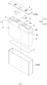
FIG. 1 is an exploded view of a battery according to an embodiment of the present disclosure. -
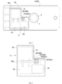
FIG. 2 is a schematic view showing positions of a signal detecting component and a cover according to an embodiment of the present disclosure. -
FIG. 3 is a schematic view of the signal detecting component according to an embodiment of the present disclosure. - In the drawings:
1, insulating member; 2, outer housing; 21, case; 22, cover; 3, information obtaining component; 31, power supply battery; 32, circuit board; 33, wireless transmitting end; 34, detection signal line; 341, temperature signal line; 342, pressure signal line; 35, sealing shell; 351, second receiving cavity; 4, pole; 5, cell; 51, first cell pack; 52, second cell pack; 53, tab; 54, mounting face; 6, connector; 7, bottom sheet; 8, protective film. - In order to illustrate the technical problems to be solved by the present disclosure, technical solutions provided by the present disclosure, and technical effects achieved by the present disclosure more clearly, the technical solutions of the embodiments of the present disclosure will be described in further detail in the following by referring to the accompanying drawings. Obviously, the described embodiments show only a part of but not all of the embodiments of the present disclosure. All other embodiments, which are obtained by any ordinary skilled person in the art based on the embodiments in the present disclosure without any creative work, shall fall within the scope of the present disclosure.
- In the description of the present disclosure, unless otherwise expressly provided and limited, the terms "connected", "coupled", and "fixed" shall be understood broadly. For example, the terms may mean fixed connection, detachable connection or structures being configured as a one-piece and integral structure; mechanical connection or electrical connection; direct connection or indirect connection through an intermediate medium; two elements being internally connected with each other or an interaction between two elements. Any ordinary skilled person in the art shall understand the specific meaning of the above terms herein depending on specific cases.
- As shown in
FIG. 1 andFIG. 2 , the present disclosure provides a battery, including anouter housing 2 and acell 5. Thecell 5 is received in a first receiving cavity of theouter housing 2. Theouter housing 2 is arranged with an insulatingmember 1. Aninformation obtaining component 3 is received in the first receiving cavity. Theinformation obtaining component 3 is fixed to thecell 5. Theinformation obtaining component 3 includes a detection assembly, apower supply battery 31, awireless transmitting end 33, and acircuit board 32. The detection assembly, thepower supply battery 31, and thewireless transmitting end 33 are electrically connected to each other through thecircuit board 32. An detection end of the detection assembly is attached to thecell 5. Thewireless transmitting end 33 is disposed adjacent to the insulatingmember 1, such that a signal emitted by thewireless transmitting end 33 may pass through the insulatingmember 1 to reach an exterior of the first receiving cavity. For example, thewireless transmitting end 33 is disposed at an end of theinformation obtaining component 3 near the insulatingmember 1. The insulatingmember 1 may have a first orthographic projection on acover 22 of theouter housing 2, and a side of theinformation obtaining component 3 near thewireless transmitting end 33 may have a second orthographic projection on thecover 22 of theouter housing 2. The first orthographic projection may be connected to the second orthographic projection. In some embodiments, there may be no intersection between the first orthographic projection and the second orthographic projection, as long as a distance between the two projections allows the signal emitted by thewireless transmitting end 33 to pass through the insulatingmember 1 to reach the exterior of the receiving cavity. Since theinformation obtaining component 3 is disposed inside the battery and the obtained information are transmitted to the outside by transmitting wireless signals, theouter housing 2 may not define any hole. In this way, the production cost of the battery may be reduced, and versatility of theinformation obtaining component 3 may be improved. Thepower supply battery 31 is arranged inside theinformation obtaining component 3, i.e., theinformation obtaining component 3 has an independent power supply, theinformation obtaining component 3 operates independently. On the one hand, theinformation obtaining component 3 does not consume any electrical energy of the battery. On the other hand, failure of theinformation obtaining component 3 may not cause any systemic risk of the overall battery, ensuring reliability of thecell 5. Since thewireless transmitting end 33 is disposed adjacent to the insulatingmember 1, the wireless signals emitted by thewireless transmitting end 33 may not be shielded internally, ensuring thewireless transmitting end 33 to successfully transmit the obtained battery information to the exterior of the battery. - In the present embodiment, the
outer housing 2 is made of metal. Theouter housing 2 includes acase 21 and acover 22. Thecase 21 is an aluminium case, and the insulatingmember 1 is arranged on thecover 22. - Further, the
pole 4 extends through the insulatingmember 1 and thecover 22. That is, the insulatingmember 1 is disposed between an end of thepole 4 and theouter housing 2. The other end of thepole 4 extends through the insulatingmember 1 and thecover 22 to be further received in the first receiving cavity. Theinformation obtaining component 3 is arranged on a side of thecell 5 near thepole 4. In the present embodiment, the insulatingmember 1 and thepole 4 are inherently arranged in the battery, and since theinformation obtaining component 3 is disposed on the side of thecell 5 near thepole 4, the structures, which are inherently arranged in the battery, may be configured to assist in transmitting the wireless signals. In this way, thecase 2 is not arranged with any additional insulating structure, and the production cost of the battery is reduced. - As shown in
FIG. 2 and FIG. 3 , the detection assembly further includes adetection signal line 34. An end of thedetection signal line 34 is connected to thecircuit board 32, and the other end of thedetection signal line 34 is arranged with a detection end. Thecell 5 includes afirst cell pack 51 and asecond cell pack 52. Thedetection signal line 34 is disposed between thefirst cell pack 51 and thesecond cell pack 52. The detection end detects an attachment face of thefirst cell pack 51 and an attachment face of thesecond cell pack 52. Specifically, thefirst cell pack 51 has afirst attachment face 511 facing thecover 22, and thesecond cell pack 52 has asecond attachment face 521 facing thecover 22. That is, the detection end detects information of thefirst attachment face 511 of thefirst cell pack 51 and thesecond attachment face 521 of thesecond cell pack 52. It can be understood that, thefirst cell pack 51 and thesecond cell pack 52 generate heat while being operating. Heat of a part thefirst cell pack 51 for attachment and heat of a part of thesecond cell pack 52 for attachment may not be dissipated easily. That is, the first attachment face of thefirst cell pack 51 and the second attachment face of thesecond cell pack 52 are locations where heat can be gathered and the highest temperature can be generated. By setting the detection end on the first attachment face of thefirst cell pack 51 and the second attachment face of thesecond cell pack 52, the highest temperature of thecell 5 can be detected, such that a current state of the battery can be determined accurately. - In some embodiments, a heat-homogenization plate (not shown in the drawings) is arranged on both the
first cell pack 51 and thesecond cell pack 52. The heat-homogenization plate defines an avoidance groove. The avoidance groove is defined to receive thedetection signal line 34. It is understandable that, while the battery is being charged and discharged, various parts of the first attachment face of thefirst cell pack 51 and the second attachment face of thesecond cell pack 52 may have different temperatures. However, a range that can be detected by the detection end is limited. The detection end may detect a temperature of a point-sized region and may not be able to detect various regions of the attachment faces. The heat-homogenization plate is arranged on both thefirst cell pack 51 and thesecond cell pack 52. Therefore, heat accumulated locally in thefirst cell pack 51 and thesecond cell pack 52 may be transmitted to the detection end through the heat-homogenization plate, such that the detection end may accurately detect an actual temperature of thefirst cell pack 51 and thesecond cell pack 52. Accuracy of the detection is improved. In the present embodiment, the heat-homogenization plate is a copper plate. - Further, the
information obtaining component 3 further includes a sealingshell 35. The sealingshell 35 has asecond receiving cavity 351. Thepower supply battery 31, thewireless transmitting end 33, and thecircuit board 32 are received in the second receivingcavity 351. It is understood that the first receiving cavity of theouter housing 2 is filled with electrolyte. While the battery is being charged and discharged, charged particles may enter the electrolyte to electrify the electrolyte. Since thepower supply battery 31, thewireless transmitting end 33, thecircuit board 32 and other structures of theinformation obtaining component 3 are received in the second receivingcavity 351 of the sealingshell 35, the above structures may be prevented from contacting the electrolyte, such that theinformation obtaining component 3 may not have a short circuit due to being interfered by the electrolyte. On the other hand, since the rest elements of theinformation obtaining component 3 are received in the second receivingcavity 351 of the sealingshell 35, integration of theinformation obtaining component 3 is improved, enabling theinformation obtaining component 3 to be mounted and fixed easily. In the present embodiment, an end of thedetection signal line 34 is connected to thecircuit board 32, and the other end of thedetection signal line 34 is the detection end. The detection end passes through the sealingshell 35 to be received in the avoidance groove and to be attached to the heat-homogenization plate and a portion of a surface of thecell 5. The portion of the surface of thecell 5 attached with the detection end serve as a groove wall of the avoidance groove. - In the present embodiment, the
case 22 of theouter housing 2 is arranged with apole 4, and thepole 4 extends through thecase 22. Thepole 4 is connected to thecell 5. The sealingshell 35 abuts against a circumferential face of thepole 4. The sealingshell 35 is insulated from thepole 4. In the present embodiment, theinformation obtaining component 3 is fixed to thecell 5. Thecell 5 has a mounting face 54 (formed by thefirst attachment face 511 of the first cell pack and thesecond attachment face 521 of the second cell pack). The mountingface 54 is arranged with atab 53. Theinformation obtaining component 3 is disposed on the mountingface 54. That is, theinformation obtaining component 3 is disposed in a space between thecell 5 and thecover 22. It can be understood that the battery of the present disclosure may have a large capacity. A size of the battery may be large accordingly. Since a space needs to be reserved for connecting thetab 53 of thecell 5 to thepole 4 on thecover 22, the space between thecell 5 and thecover 22 is generated. When theinformation obtaining component 3 is received in the space, theouter housing 2 may be adapted to theinformation obtaining component 3 without modifying the structure of theouter housing 2. On the one hand, versatility of theouter housing 2 is improved. On the other hand, an energy density of the battery may not be reduced. Since the sealingshell 35 abuts against the circumferential face of thepole 4, contact positioning between the sealingshell 35 and thepole 4 may be achieved, such that assembling the sealingshell 35 and thepole 4 may be less difficult. - In an embodiment, the sealing
shell 35 is a non-metallic shell. Since the sealingshell 35 is non-metallic, theentire sealing shell 35 is insulated. Any conductive material from the outside may not enter the second receivingcavity 351 of the sealingshell 35, elements in the second receivingcavity 351 may not have short circuits. Exemplarily, the sealingshell 35 may be made of polyethylene glycol terephthalate (PET), polypropylene (PP); the sealingshell 35 may be shaped by film blister moulding. Alternatively, the sealingshell 35 may be formed by injection moulding, and treatments of high-frequency welding and ultrasonic waves may be performed to achieve sealing and insulating. The sealingshell 35 may be overall L-shaped to allow thepower supply battery 31, thecircuit board 32, and thewireless transmitting end 33 to be arranged conveniently. - In another embodiment, the insulating
member 1 is disposed between thepole 4 and thecover 22 of theouter housing 2. The sealingshell 35 abuts against the insulatingmember 1. It is understood that thepole 4, thecover 22, and the insulatingmember 1 are inherently arranged in the battery. Arranging the insulatingmember 1 between thepole 4 and thecover 22 prevents thepole 4 from contacting thecover 22, such that a short circuit of the battery may be avoided. By arranging the sealingshell 35 to abut against the insulatingmember 1, the inherently arranged insulating structure may be taken to prevent theinformation obtaining component 3 from having the short circuit with thepole 4. In the present embodiment, the sealingshell 35 may be a metal shell. Of course, in this case, the sealingshell 35 needs to be insulated from thecircuit board 32 and other electric structures, such as thepower supply battery 31, such that theinformation obtaining component 3 may be prevented from being short-circuited by conductive substances carried by the electrolyte in the first receiving cavity. The sealingshell 35 may be spaced apart from thecircuit board 32 and other electric structures to achieve insulation. Alternatively, an insulating layer may be arranged on an inner wall of the sealingshell 35. The sealingshell 35 may be a non-metallic shell. Thenon-metallic sealing shell 35 may be made of polyethylene glycol terephthalate (PET) or polypropylene (PP). Thenon-metallic sealing shell 35 may be formed by film blister moulding. Alternatively, thenon-metallic sealing shell 35 may be an injection moulding shell, and high-frequency welding and ultrasonic operations may be performed to achieve insulation. - In the present embodiment, the sealing
shell 35 is the non-metallic shell and abuts against the insulatingmember 1. - In some embodiments, the
information obtaining component 3 is adhered to thecell 5. In the present embodiment, theinformation obtaining component 3 is adhered to thecell 5 by a tape. It is understood that thecell 5 includes an electrode sheet, a diaphragm and so on. The structure of thecell 5 is complex and includes electric elements. When theinformation obtaining component 3 is fixed to theelectric core 5 by adhesion, the battery may be assembled less difficultly, and production cost of the battery may be reduced. - In the present embodiment, the
detection signal line 34 of theinformation obtaining component 3 includes apressure signal line 342 and atemperature signal line 341. Thepressure signal line 342 is configured to collect a pressure of thecell 5, and thetemperature signal line 341 is configured to collect a temperature of thecell 5. - In the present embodiment, the
cell 5 has a mountingface 54 facing towards thecover 22. The mountingface 54 is arranged with thetab 53. Theinformation obtaining component 3 is arranged on the mountingface 54. Twoinformation obtaining components 3 may be arranged. Thetab 53 is disposed between the twoinformation obtaining components 3. In the present embodiment, the size of the battery is large. The twoinformation obtaining components 3 are arranged to detect temperatures and pressures at various locations of thecell 5 more comprehensively, such that accuracy of the detection is improved. In other embodiments, the number ofinformation obtaining components 3 is not limited to two, i.e., three, four or moreinformation obtaining components 3 may be arranged. The number ofinformation obtaining components 3 may be determined according to the actual demands of the battery. - The
cell 5 includes thefirst cell pack 51 and thesecond cell pack 52. In an embodiment, one of the twoinformation obtaining components 3 collects information of thefirst cell pack 51, and the other one of the twoinformation obtaining components 3 collects information of thesecond cell pack 52. When the twoinformation obtaining components 3 are arranged to collect information of thefirst cell pack 51 and thesecond cell pack 52 respectively, an operational state of thefirst cell pack 51 and an operational state of thesecond cell pack 52 may be determined independent from each other, and the state of the entire battery may be determined accordingly. In another embodiment, the twoinformation obtaining components 3 cooperatively collect both the information of thefirst cell pack 51 and the information of thesecond cell pack 52. One of the twoinformation obtaining components 3 collects information of a left region of the attachment face of thefirst cell pack 51 and thesecond cell pack 52, and the other one of the twoinformation obtaining components 3 collects information of a right region of the attachment face of thefirst cell pack 51 and thesecond cell pack 52. - In the present embodiment, an outer periphery of the
cell 5 is wrapped by aprotective film 8. The battery further includes abottom sheet 7 and aconnector 6. Thebottom sheet 7 and theconnector 6 are both received in the first receiving cavity of theouter housing 2. Thebottom sheet 7 is located at a bottom of thecell 5. Theconnector 6 is disposed between thecover 22 and thecell 5. Theconnector 6 is configured to connect thetab 53 of thecell 5 to thepole 4 on thecover 22. Thecircuit board 32 may be a printed circuit board (PCB). Thewireless transmitting end 33 of theinformation obtaining component 3 is a signal transmitting antenna. Thepower supply battery 31 is a primary lithium battery, such as a lithium-manganese dioxide battery, a lithium thionyl chloride battery, and so on. - In the description herein, it is to be understood that the terms "up", "down", "left", "right", and so on indicate orientation or positional relationships shown in the accompanying drawings and are used only for the purpose of facilitating description and simplifying operations. These terms are not intended to indicate or imply that the device or the element must be constructed or operated in the particular orientation. Therefore, the terms shall not be interpreted as limitation of the present disclosure. In addition, the terms "first" and "second" are used only for describing distinguishing features and have no special meaning.
- In the description of the present disclosure, the description with reference to the terms "embodiment", "example", and so on means that a specific feature, a structure, a material, or characteristic described in the embodiment or the example is included in at least one embodiment or example of the present disclosure. In the present specification, schematic expressions of the above terms do not necessarily refer to the same embodiment or example.
- In addition, it should be understood that although the present specification is described in accordance with the embodiments, not each embodiment includes only one independent technical solution. The specification is described in such a manner merely for clarity. Any ordinary skilled person in the art shall take the specification as a whole. Technical solutions in various embodiments may be appropriately combined with each other to form other embodiments that may be understood by the ordinary skilled person in the art.
- Technical principles of the present disclosure are described above by referring to specific embodiments. The description is only intended to explain the principles of the present disclosure and is not to limit the scope of the present disclosure. Based on the explanations herein, any other implementation, which is associated by any ordinary skilled person in the art without making creative work, shall fall within the scope of the present disclosure.
Claims (13)
- A battery, comprising an outer housing (2) and a cell (5), wherein the cell (5) is received in a first receiving cavity of the outer housing (2), the outer housing (2) is arranged with an insulating member (1), and the battery is characterized by comprising:
at least one information obtaining component (3), received in the first receiving cavity and fixed to the cell (5), wherein each of the at least one information obtaining component (3) comprises a detection assembly, a power supply battery (31), a wireless transmitting end (33) and a circuit board (32); the detection assembly, the power supply battery (31), and the wireless transmitting end (33) are electrically connected with each other via the circuit board (32); a detection end of the detection assembly is attached to the cell (5), the wireless transmitting end (33) is disposed adjacent to the insulating member (1) and is configured to transmit a signal, and the signal is capable of transmitting through the insulating member (1) to reach an exterior of the first receiving cavity. - The battery according to claim 1, further comprising:
a pole (4), extending through the insulating member (1) and the outer housing (2), wherein the insulating member (1) is disposed between an end of the pole (4) and the outer housing (2), the other end of the pole (4) is received in the first receiving cavity; and the at least one information obtaining component (3) is arranged on a side of the cell (5) near the pole (4). - The battery according to claim 2, wherein, the detection assembly comprises a detection signal line (34);an end of the detection signal line (34) is connected to the circuit board (32), the other end of the detection signal line (34) is arranged with the detection end;the cell (5) comprises a first cell pack (51) and a second cell pack (52), the detection signal line (34) is disposed between the first cell pack (51) and the second cell pack (52);the detection end is configured to detect information of a first attachment face (511) of the first cell pack (51) and information of a second attachment face (521) of the second cell pack (52), and the attachment face is a surface to which the detection end is attached.
- The battery according to claim 3, wherein a heat-homogenization plate is arranged on both the first cell pack (51) and the second cell pack (52); the heat-homogenization defines an avoidance groove; and the detection signal line (34) is received in the avoidance groove.
- The battery according to claim 1, wherein each of the at least one information obtaining component (3) further comprises a sealing shell (35); the sealing shell (35) has a second receiving cavity; the power supply battery (31), the wireless transmitting end (33), and the circuit board (32) are received in the second receiving cavity.
- The battery according to claim 5, further comprising:
a pole (4), extending through the outer housing (2), wherein, the pole (4) is connected to the cell (5), the sealing shell (35) abuts against a circumferential face of the pole (4), and the sealing shell (35) is insulated from the pole (4). - The battery according to claim 6, wherein, the sealing shell (35) is non-metallic.
- The battery according to claim 6, wherein, the insulating member (1) is disposed between the pole (4) and the outer housing (2), and the sealing shell (35) abuts against the insulating member (1).
- The battery according to claim 1, wherein the at least one information obtaining component (3) is adhered to the cell (5).
- The battery according to claim 1, wherein the number of the at least one information obtaining component (3) is at least two.
- The battery according to claim 10, wherein, the number of the at least one information obtaining component (3) is two, the cell (5) has a mounting face (54), a tab (53) is arranged on the mounting face (54), the two information obtaining components (3) are arranged on the mounting face (54), the tab (53) is disposed between the two information obtaining components (3).
- The battery according to claim 11, wherein the cell (5) comprises a first cell pack (51) and a second cell pack (52); one of the two information obtaining components (3) is configured to detect information on a first attachment face (511) of the first cell pack (51); and the other one of the two information obtaining components (3) is configured to detect information on a second attachment face of the second cell pack (52).
- The battery according to claim 3, wherein, the detection signal line (34) comprises a temperature signal line (341) and a pressure signal line (342);the information of the attachment face comprises a temperature of the attachment face and a pressure of the attachment face; andthe temperature signal line (341) is configured to detect the temperature of the attachment face; and the pressure signal line (342) is configured to detect the pressure of the attachment face.
Applications Claiming Priority (1)
| Application Number | Priority Date | Filing Date | Title |
|---|---|---|---|
| CN202321965532.XU CN220439796U (en) | 2023-07-25 | 2023-07-25 | Battery |
Publications (2)
| Publication Number | Publication Date |
|---|---|
| EP4498474A1 true EP4498474A1 (en) | 2025-01-29 |
| EP4498474B1 EP4498474B1 (en) | 2025-12-03 |
Family
ID=89223621
Family Applications (1)
| Application Number | Title | Priority Date | Filing Date |
|---|---|---|---|
| EP23217566.1A Active EP4498474B1 (en) | 2023-07-25 | 2023-12-18 | Battery |
Country Status (4)
| Country | Link |
|---|---|
| US (1) | US20250038278A1 (en) |
| EP (1) | EP4498474B1 (en) |
| CN (1) | CN220439796U (en) |
| WO (1) | WO2025020421A1 (en) |
Citations (4)
| Publication number | Priority date | Publication date | Assignee | Title |
|---|---|---|---|---|
| US20150132614A1 (en) * | 2013-11-12 | 2015-05-14 | Infineon Technologies Ag | Sensor arrangement, energy system and method |
| US20150301113A1 (en) * | 2010-09-10 | 2015-10-22 | Johnson Controls Technology Company | Vehicle battery monitoring system |
| CN114678607A (en) * | 2022-03-01 | 2022-06-28 | 华为数字能源技术有限公司 | A battery cover, battery and power system |
| WO2023010798A1 (en) * | 2020-09-29 | 2023-02-09 | 欣旺达电动汽车电池有限公司 | Battery cell, battery module, battery pack and electric vehicle |
Family Cites Families (4)
| Publication number | Priority date | Publication date | Assignee | Title |
|---|---|---|---|---|
| KR20150009877A (en) * | 2013-07-17 | 2015-01-27 | 삼성에스디아이 주식회사 | Rechargeable battery |
| CN217641491U (en) * | 2022-05-20 | 2022-10-21 | 杭州高特电子设备股份有限公司 | Battery with built-in information acquisition and wireless transmission |
| CN217641497U (en) * | 2022-05-20 | 2022-10-21 | 杭州高特电子设备股份有限公司 | Information acquisition and monitoring device of lithium battery |
| CN218867200U (en) * | 2022-11-09 | 2023-04-14 | 湖南华兴新能源科技有限公司 | Intelligent battery |
-
2023
- 2023-07-25 CN CN202321965532.XU patent/CN220439796U/en active Active
- 2023-12-08 WO PCT/CN2023/137568 patent/WO2025020421A1/en active Pending
- 2023-12-15 US US18/540,908 patent/US20250038278A1/en active Pending
- 2023-12-18 EP EP23217566.1A patent/EP4498474B1/en active Active
Patent Citations (5)
| Publication number | Priority date | Publication date | Assignee | Title |
|---|---|---|---|---|
| US20150301113A1 (en) * | 2010-09-10 | 2015-10-22 | Johnson Controls Technology Company | Vehicle battery monitoring system |
| US20150132614A1 (en) * | 2013-11-12 | 2015-05-14 | Infineon Technologies Ag | Sensor arrangement, energy system and method |
| WO2023010798A1 (en) * | 2020-09-29 | 2023-02-09 | 欣旺达电动汽车电池有限公司 | Battery cell, battery module, battery pack and electric vehicle |
| CN114678607A (en) * | 2022-03-01 | 2022-06-28 | 华为数字能源技术有限公司 | A battery cover, battery and power system |
| US20230282914A1 (en) * | 2022-03-01 | 2023-09-07 | Huawei Digital Power Technologies Co., Ltd. | Battery cover plate, battery, and power system |
Also Published As
| Publication number | Publication date |
|---|---|
| EP4498474B1 (en) | 2025-12-03 |
| CN220439796U (en) | 2024-02-02 |
| US20250038278A1 (en) | 2025-01-30 |
| WO2025020421A1 (en) | 2025-01-30 |
Similar Documents
| Publication | Publication Date | Title |
|---|---|---|
| US20240322396A1 (en) | Battery | |
| US20220416357A1 (en) | Battery, battery module, battery pack, and electric vehicle | |
| US12456764B2 (en) | Battery module | |
| US20180288889A1 (en) | Circuit board and battery architecture of an electronic device | |
| EP4184678B1 (en) | Battery pack and electronic device comprising same | |
| US20250297911A1 (en) | Information collection device and battery pack | |
| EP4618232A1 (en) | Cover plate assembly, battery, energy storage device, and power consuming device | |
| US20250279490A1 (en) | Battery Pack | |
| KR20230035375A (en) | batteries and electrical devices | |
| CN115332696A (en) | Battery and electric equipment | |
| US20250266488A1 (en) | Battery and electronic apparatus | |
| CN111989800B (en) | Batteries and electrical devices having said batteries | |
| CN220324515U (en) | Batteries, battery modules and power equipment | |
| CN220021225U (en) | Batteries, battery modules and battery packs | |
| EP4498474A1 (en) | Battery | |
| WO2012081384A1 (en) | Power storage cell and power storage apparatus | |
| US12452353B2 (en) | Electronic device | |
| CN113437350B (en) | Battery | |
| US20250046972A1 (en) | Battery and electronic device | |
| CN220604757U (en) | Power Battery | |
| EP4439800A1 (en) | Heating device, electrochemical device, and electrical device | |
| JP2004185861A (en) | Circuit board and battery pack | |
| JP2025521039A (en) | Batteries and Electronic Devices | |
| CN212323083U (en) | Battery and powered device having the same | |
| EP4618233A1 (en) | Chip assembly for battery, battery, energy storage device, and electrical device |
Legal Events
| Date | Code | Title | Description |
|---|---|---|---|
| PUAI | Public reference made under article 153(3) epc to a published international application that has entered the european phase |
Free format text: ORIGINAL CODE: 0009012 |
|
| STAA | Information on the status of an ep patent application or granted ep patent |
Free format text: STATUS: EXAMINATION IS IN PROGRESS |
|
| 17P | Request for examination filed |
Effective date: 20231226 |
|
| AK | Designated contracting states |
Kind code of ref document: A1 Designated state(s): AL AT BE BG CH CY CZ DE DK EE ES FI FR GB GR HR HU IE IS IT LI LT LU LV MC ME MK MT NL NO PL PT RO RS SE SI SK SM TR |
|
| GRAP | Despatch of communication of intention to grant a patent |
Free format text: ORIGINAL CODE: EPIDOSNIGR1 |
|
| STAA | Information on the status of an ep patent application or granted ep patent |
Free format text: STATUS: GRANT OF PATENT IS INTENDED |
|
| INTG | Intention to grant announced |
Effective date: 20250717 |
|
| GRAS | Grant fee paid |
Free format text: ORIGINAL CODE: EPIDOSNIGR3 |
|
| GRAA | (expected) grant |
Free format text: ORIGINAL CODE: 0009210 |
|
| STAA | Information on the status of an ep patent application or granted ep patent |
Free format text: STATUS: THE PATENT HAS BEEN GRANTED |
|
| AK | Designated contracting states |
Kind code of ref document: B1 Designated state(s): AL AT BE BG CH CY CZ DE DK EE ES FI FR GB GR HR HU IE IS IT LI LT LU LV MC ME MK MT NL NO PL PT RO RS SE SI SK SM TR |
|
| REG | Reference to a national code |
Ref country code: CH Ref legal event code: F10 Free format text: ST27 STATUS EVENT CODE: U-0-0-F10-F00 (AS PROVIDED BY THE NATIONAL OFFICE) Effective date: 20251203 Ref country code: GB Ref legal event code: FG4D |
|
| REG | Reference to a national code |
Ref country code: DE Ref legal event code: R096 Ref document number: 602023009274 Country of ref document: DE |
|
| REG | Reference to a national code |
Ref country code: IE Ref legal event code: FG4D |
|
| PGFP | Annual fee paid to national office [announced via postgrant information from national office to epo] |
Ref country code: AT Payment date: 20260113 Year of fee payment: 3 |
|
| REG | Reference to a national code |
Ref country code: NL Ref legal event code: MP Effective date: 20251203 |
|
| PG25 | Lapsed in a contracting state [announced via postgrant information from national office to epo] |
Ref country code: ES Free format text: LAPSE BECAUSE OF FAILURE TO SUBMIT A TRANSLATION OF THE DESCRIPTION OR TO PAY THE FEE WITHIN THE PRESCRIBED TIME-LIMIT Effective date: 20251203 |
|
| REG | Reference to a national code |
Ref country code: LT Ref legal event code: MG9D |
|
| PG25 | Lapsed in a contracting state [announced via postgrant information from national office to epo] |
Ref country code: NO Free format text: LAPSE BECAUSE OF FAILURE TO SUBMIT A TRANSLATION OF THE DESCRIPTION OR TO PAY THE FEE WITHIN THE PRESCRIBED TIME-LIMIT Effective date: 20260303 |
|
| PGFP | Annual fee paid to national office [announced via postgrant information from national office to epo] |
Ref country code: DE Payment date: 20260218 Year of fee payment: 3 |
|
| PG25 | Lapsed in a contracting state [announced via postgrant information from national office to epo] |
Ref country code: FI Free format text: LAPSE BECAUSE OF FAILURE TO SUBMIT A TRANSLATION OF THE DESCRIPTION OR TO PAY THE FEE WITHIN THE PRESCRIBED TIME-LIMIT Effective date: 20251203 Ref country code: HR Free format text: LAPSE BECAUSE OF FAILURE TO SUBMIT A TRANSLATION OF THE DESCRIPTION OR TO PAY THE FEE WITHIN THE PRESCRIBED TIME-LIMIT Effective date: 20251203 |
|
| PG25 | Lapsed in a contracting state [announced via postgrant information from national office to epo] |
Ref country code: RS Free format text: LAPSE BECAUSE OF FAILURE TO SUBMIT A TRANSLATION OF THE DESCRIPTION OR TO PAY THE FEE WITHIN THE PRESCRIBED TIME-LIMIT Effective date: 20260303 |
|
| PGFP | Annual fee paid to national office [announced via postgrant information from national office to epo] |
Ref country code: FR Payment date: 20260225 Year of fee payment: 3 |
|
| PGFP | Annual fee paid to national office [announced via postgrant information from national office to epo] |
Ref country code: TR Payment date: 20260302 Year of fee payment: 3 |
|
| PG25 | Lapsed in a contracting state [announced via postgrant information from national office to epo] |
Ref country code: PL Free format text: LAPSE BECAUSE OF FAILURE TO SUBMIT A TRANSLATION OF THE DESCRIPTION OR TO PAY THE FEE WITHIN THE PRESCRIBED TIME-LIMIT Effective date: 20251203 |
|
| PG25 | Lapsed in a contracting state [announced via postgrant information from national office to epo] |
Ref country code: LV Free format text: LAPSE BECAUSE OF FAILURE TO SUBMIT A TRANSLATION OF THE DESCRIPTION OR TO PAY THE FEE WITHIN THE PRESCRIBED TIME-LIMIT Effective date: 20251203 |