EP4498397A1 - Multi-use control system for switchgear module with guided sliding element - Google Patents
Multi-use control system for switchgear module with guided sliding element Download PDFInfo
- Publication number
- EP4498397A1 EP4498397A1 EP23188074.1A EP23188074A EP4498397A1 EP 4498397 A1 EP4498397 A1 EP 4498397A1 EP 23188074 A EP23188074 A EP 23188074A EP 4498397 A1 EP4498397 A1 EP 4498397A1
- Authority
- EP
- European Patent Office
- Prior art keywords
- switchgear module
- rotating
- rotating element
- control system
- angular positions
- Prior art date
- Legal status (The legal status is an assumption and is not a legal conclusion. Google has not performed a legal analysis and makes no representation as to the accuracy of the status listed.)
- Pending
Links
Images


Classifications
-
- H—ELECTRICITY
- H01—ELECTRIC ELEMENTS
- H01H—ELECTRIC SWITCHES; RELAYS; SELECTORS; EMERGENCY PROTECTIVE DEVICES
- H01H33/00—High-tension or heavy-current switches with arc-extinguishing or arc-preventing means
- H01H33/02—Details
- H01H33/46—Interlocking mechanisms
- H01H33/48—Interlocking mechanisms for interlocking between casing or cover and mechanism for operating contacts
Definitions
- the present disclosure relates to industrial automation.
- the present disclosure relates to a multi-use control system for a switchgear module, a switchgear module comprising a multi-use control system and a method for operating a switchgear module by means of a multi-use control system.
- Switchgear technology is widely implemented in electrical power systems, such as industrial automation and robotic systems, in order to provide effective control and reliable protection for the embedded electrical components.
- switchgear modules may regulate power distribution within the electrical power systems, ensuring efficient operation and optimal management of electrical loads. Equipped with protective components such as circuit breakers and fuses, such switchgear modules may safeguard against overcurrent and short circuits, minimizing the risk of equipment damage or accidents. Further, these modules may offer flexibility in installation, expansion, and maintenance, for example for the the automation and robotic systems. It may thus be of great importance that these switchgear modules may be implemented and operated in a well-controlled manner.
- a multi-use control system for a switchgear module.
- the multi-use control system comprises a first rotating element that comprises a sliding element, a second rotating element, which comprises an elongated opening and is connectable to the switchgear module that is switchable between a plurality of modes of operation, and an interlocking element that is configured to secure the switchgear module to or release the switchgear module from a compartment.
- the first rotating element is connectable to an operating element that is rotatable between a plurality of angular positions comprising a first group of angular positions and a second group of angular positions.
- the sliding element is configured to interconnect with and slide along the elongated opening, and to transmit a rotational motion from the first rotating element to the second rotating element for switching the switchgear module between the plurality of modes of operation, when the operating element rotates between the first group of angular positions.
- the sliding element is configured to disconnect from the elongated opening and to allow the first rotating element transmitting the rotational motion to the interlocking element for securing or releasing the switchgear module, when the operating element rotates between the second group of angular positions.
- the first rotating element and the second rotating element may be coupled and interconnected with each other in a so-called internal Geneva-like drive mechanism by means of the interacting sliding element of the first rotating element and the elongated opening arranged at the second rotation element.
- the first rotating element, the second rotating element and the operating element may form a switching assembly, which may perform a switching mechanism for the switchgear module, since the second rotating element may further be connected to a main switch of the switchgear module.
- the first rotating element may come into contact or collide with the interlocking element and drive the interlocking element to move and/or rotate, for example to unlock the secured switchgear module inside the compartment.
- the first rotating element, the interlocking element and the operating element may form together an interlocking assembly, which may perform an interlocking mechanism for the switchgear module.
- the Geneva-like drive mechanism for the first and second rotating elements via the sliding element and the elongated opening may transmit the angular position of the operating element to the main switch inside the switchgear module. Beyond the turning angle, the transmission may be interrupted.
- the interlocking mechanism may be released and the switchgear module may be brought into a releasing or moving position. If the operating element may get turned in the opposite direction, the interlocking mechanism may first lock the switchgear module in the compartment and then start to transmit the rotational motion of the operating element to the main switch being or connected to the second rotating element.
- the control system may be designed to allow separate controlling over the switching assembly for the switching mechanism of the switchgear module or over the interlocking assembly for the interlocking mechanism of the switchgear module by means of the internal Geneva-like drive mechanism between the first and second rotating elements and the additionally arranged interlocking system. Further the control system may be designed to allow a seamless transition between the switching mechanism and the interlocking mechanism.
- the compartment may be a housing, in which the switchgear module may be placed or mounted, so that the switchgear module may be operated under a safety condition.
- the switchgear module may be released or detached from the compartment while not being operated.
- the switchgear module may be designed as a withdrawable switchgear module.
- the withdrawable switchgear module may be a low-voltage switchgear module.
- the rotating lever arm may be designed to be elongated rod-shaped extending between the proximal end and the distal end.
- the first rotating element may exercise a force to drive the connected second rotating element to rotate and thus transmit the rotational motion, when the operating element may rotate between the first group of angular positions for switching the modes of operation of the switchgear module.
- the sliding element may be arranged at the distal end of the first rotating element.
- the multi-use control system may further comprise the operating element, which may be a handle that is configured to connect to the first rotating element at the proximal end via a shaft.
- the operating element which may be a handle that is configured to connect to the first rotating element at the proximal end via a shaft.
- the operating element may be configured to control the switching assembly to switch the switchgear module between the plurality of modes of operation, when pivoting between the first group of angular positions, and to control the interlocking assembly to secure or release the switchgear module, when pivoting between the second group of angular positions.
- the operating element may be arranged on the front of the switchgear module. Further, the operating element and the shaft may be connected to the first rotating element at the proximal end of the first rotating element, so that the driving force may be transmitted from the handle to the first rotating element.
- the first rotating element may be configured to rotate about a first rotational axis passing through the proximal end of the first rotating element, when the operating element may rotate between the plurality of angular positions.
- the first rotational axis of the first rotating element may be vertical to the elongated rotating lever arm.
- the proximal end of the first rotating element may thus be a first rotating point. Since the operating element may be connected to the first rotating element via the shaft at the proximal end, the operating element and the connecting shaft may also be configured to rotate about the same first rotational axis.
- the sliding element may be a sliding pin, a sliding clamp or a sliding screw.
- the elongated opening may comprise a first end and a second end.
- the sliding element of the first rotating element may be configured to be guided to slide between the first end and second end of the elongated opening, and to drive the second rotating element to rotate about a second rotational axis, when the operating element may rotate between the first group of angular positions.
- the elongated opening may be designed as a slot or a rail for the sliding element and configured to guide the sliding element to move or slide along the rail, after the sliding element may be coupled or connected to to the elongated opening.
- the second rotational axis of the second rotating element may be arranged in parallel to the first rotational axis of the first rotating element.
- the second rotating element may also comprise an elongated shape extending from a second rotating point of the second rotating element may be arranged, to the second end of the elongated opening of the second rotating element.
- the first end of the second rotating element may be a closed end and the second end of the elongated opening may be an open end.
- the sliding element may be configured to slide off the elongated opening at the open end, when the operating element may rotate between the second group of angular positions.
- the sliding element when the operating element may drive the first rotation element to rotate or pivot in a direction, preferably in a clockwise direction for a transition from the switching mechanism towards the interlocking mechanism, the sliding element may be configured to slide from the first, closed end of the elongated opening to the second, open end of the elongated opening, at which the sliding element may further slide off the elongated opening.
- the sliding of the sliding element may be configured to convert the rotational motion of the first rotating element into the rotational motion of the second rotation element about the second rotating axis passing through the second rotation point of the second rotation element.
- the second rotation point may be arranged at the opposite end of the elongated second rotating element to the second, open end of the elongated opening.
- the second rotation point may be arranged between the opposite end of the second rotating element and the second, open end of elongated opening.
- the second rotating element may rotate in a corresponding direction or a clockwise direction.
- the plurality of modes of operation of the switchgear module may comprise a first mode of operation, a second mode of operation and/or a third mode of operation.
- the first group of angular positions of the operating element may comprise a first angular position, which may be configured to interconnect with the first mode of operation of the switchgear module, and a second angular position, which may be configured to interconnect with the second mode of operation of the switchgear module, and/or a third angular position, which may be configured to interconnect with the third mode of operation of the switchgear module.
- the first mode of operation of the switchgear module may be an ON-mode
- the second mode of operation of the switchgear module may be an OFF-mode
- the third mode of operation of the switchgear module may be an TEST-mode
- the first angular position of the operating element may be a 0° angular positon
- the second angular position of the operating element may be a 90° angular positon or a 135° angular position
- the third angular position of the operating element may be a 135° angular positon.
- the switchgear module In the ON-mode, the switchgear module may be inserted or secured in the compartment, a main switch of the switchgear module may be closed, the main circuit and control circuit of the switchgear module may be connected.
- the switchgear module In the OFF-mode, the switchgear module may be inserted or secured in the compartment, the main switch of the switchgear module may be open, the main circuit and the control circuit of the switchgear module may be disconnected.
- a padlocking for the switchgear module may be provided for the OFF-mode.
- the switchgear module In the TEST-mode, the switchgear module may be inserted or secured in the compartment, the main switch of the switchgear module may be open, the main circuit of the switchgear module may be disconnected.
- a padlocking for the switchgear module may be provided for the TEST-mode. Compared to the OFF-mode, the additional TEST-mode may be designed to allow the control circuit being still connected.
- the second group of angular positions of the operating element may comprise a closed angular position, which may be a 90° angular position or a 135° angular position, and an open angular position, which may be a 180° angular position.
- the sliding element may be configured to collide with the interlocking element and to transmit the rotational motion of the first rotating element to a translational motion of the interlocking element for releasing the switchgear module, when the operating element may rotate to the open angular positions.
- the interlocking element may be a rocker switch for securing the switchgear module inside the compartment.
- the interlocking element may comprise an interlocking pin being arranged at an end of the interlocking element adjacent to the first rotation element.
- the control system may be configured to allow a collision between the sliding element and the interlocking pin at the 180° angular position for a RELEASE-mode, in which the switchgear module may be released or withdrawable from the compartment.
- the closed angular position may correspond to an initial position for the switchgear module being locked or secured inside the compartment.
- the operating element may rotate between the closed and open angular positions, the first rotation element may rotate freely for a while without interacting with both the second rotating element and the interlocking element until reaching the closed or open angular position.
- the first rotating element may disconnect from the interlocking system to allow the interlocking pin moving and/or rotating back to the initial position as the closed, locking position, so that the switchgear module may be secured in the compartment again.
- the 90° or 135° angular position may be a turning angular point, by which a transition between the switching mechanism and the interlocking mechanism may take place by rotating the operating element across the turning angular point.
- the multi-use control system comprising the various components comprising the first and second rotating elements following a Geneva-like drive mechanism and the interlocking element may allow the separation and the transition of the switching and interlocking mechanisms for the switchgear module in a continuous manner using the single operating handle.
- the transition from the controlling over the switching assembly to the controlling over the interlocking assembly in the continuous direction may be performed as a result of the sliding of the sliding element of the first rotating element off the elongated opening of the second rotating element and the collision of the first rotating element with the interlocking element.
- the single operating element or handle may be arranged on the front of the switchgear module and fulfill two separate functions safely and reliably: the switching of the switching device or the main switching device into all its possible positions, such as the ON-, OFF-, TEST-positions, which may be set by various angular positions covering a first angular rage of 0°, 90° and/or 135° angular positions, and the locking or releasing the entire switchgear module inside its compartment by transmitting the rotary motion of the main handle to the interlocking element via the first rotating element, when rotating covering the second angular range or the second groups of angular positions.
- the switching of the switching device or the main switching device into all its possible positions, such as the ON-, OFF-, TEST-positions, which may be set by various angular positions covering a first angular rage of 0°, 90° and/or 135° angular positions
- the locking or releasing the entire switchgear module inside its compartment by transmitting the rotary motion of the main handle
- This mechanism may ensure that the main switching assembly may be switched to the OFF-mode and/or the TEST-mode, before the switchgear module may be released.
- the mechanism may ensure that the switching assembly may first be switched to the TEST-mode and/or OFF-mode and then to the operating ON-mode.
- the rotary motion of the operating handle on the switchgear module front may be translated to the main switching assembly via the first and second rotating elements interconnecting each other in the Geneva-like drive mechanism, so that the turning angles of the handle and the sense of the rotation of the switching assembly for the respective modes of operation may correspond to each other.
- the first angular position, the second angular position and/or the third angular position may be any angular position between 0° and 180° arranged in a sequence along the same direction for pivoting the operating element and the respective first and second pivoting elements being coupled with each other.
- the predefined turning angular position being the second or third angular position may be arranged between 0° and 180°.
- the pivoting element may drive the first pivoting element to the open angular position for releasing the switchgear module, which may be arranged, alternatively to the 180° angular position, between the turning angular position and the 180° angular position, or at a larger angular position between 180° to 360° angular positions, preferably between 180° to 270° angular positions, preferably between 180° or 225° angular positions.
- a switchgear module which comprises a multi-use control system.
- the switchgear module is a low-voltage switchgear module.
- the switchgear module may be a low-voltage switchgear module, which may be configured to operate at a voltage range between 0 V and 1000 V.
- the switchgear module may be a medium-voltage or high-voltage switchgear module.
- the multi-use control system may be integrated in the medium-voltage or high-voltage switchgear module.
- a use of a multi-use control system for a switchgear module may be provided for a safe operation of the switchgear module in an electrical power system, for example in an automatic system or a robotic system.
- the manufacturing costs for the compact control system 100 for the switchgear module may be significantly reduced.
- a method for operating a switchgear module by means of a multi-use control system comprises the following steps: connecting a first rotating element to an operating element that is rotatable between a plurality of angular positions comprising a first group of angular positions and a second group of angular positions; interconnecting the sliding element with the elongated opening, guiding the sliding element to slide along the elongated opening, and transmitting a rotational motion from the first rotating element to the second rotating element for switching the switchgear module between the plurality of modes of operation, while rotating the operating element between the first group of angular positions; disconnecting the sliding element from the elongated opening and allowing the first rotating element transmitting the rotational motion to the interlocking element for securing or releasing the switchgear module, while pivoting the operating element between the second group of angular positions.
- the method may further comprise the step of rotating the operating element in an opposite direction for securing the switchgear module to the compartment by disconnecting the first rotating element from the interlocking element, interconnecting the sliding element with the elongated opening transiting the controlling over the interlocking assembly to the controlling over the switching assembly and guiding the sliding element to slide along the elongated opening, and rotating the operating element between the first group of angular positions for switching the switchgear module between the plurality of modes of operation.
- a computer program that comprises machine-readable instructions that, when executed by one or more computers and/or compute instances, cause the one or more computers and/or compute instances to perform a method for operating a switchgear module by means of a multi-use control system in an automation or robotic system.
- a download product is an instance of the computer program that may be sold and downloaded online for immediate fulfilment in lieu of physically shipping a machine-readable data carrier.
- the method may be at least partly computer-implemented, and may be implemented in software or in hardware, or in software and hardware. Further, the method may be carried out by computer program instructions running on means that provide data processing functions.
- the data processing means may be a suitable computing means, such as an electronic control module etc., which may also be a distributed computer system.
- the data processing means or the computer respectively, may comprise one or more of a processor, a memory, a data interface, or the like.
- Fig. 1 and Fig. 2 show schematically an example of a multi-use control system 100 for a switchgear module 10, which may be a low-voltage switchgear module, respectively, in a perspective view and in a simplified side view.
- the multi-use control system 100 comprises a first rotating element 110, a second rotating element 120 and an interlocking element 220 and an operating element 160 which is also shown in Fig. 3 .
- the first rotating element 110 comprises a sliding element 115, which may be a sliding pin as shown in Fig. 1 and Fig. 2 . Further, the first rotating element 110 may be designed to be a rotating lever arm comprising a proximal end 111 and a distal end 112. The sliding element 115 is arranged at the distal end 112 of the first rotating element 110.
- the first rotating element 110 is connectable to the operating element 160 which may be designed as a handle and is rotatable between a plurality of angular positions comprising a first group of angular positions 161, 162, 163 and a second group of angular positions 163, 164, as schematically shown in Fig. 3 .
- the operating element 160 which may be designed as a handle and is rotatable between a plurality of angular positions comprising a first group of angular positions 161, 162, 163 and a second group of angular positions 163, 164, as schematically shown in Fig. 3 .
- the first rotating element 110 is connected with the operating element 160 and the shaft 150 at the proximal end 111.
- the first rotating element 110 may be configured to rotate about a first rotational axis passing through the proximal end 111 of the first rotating element 110, along with the shaft 150 and the operating element 160, when the operating element 160 may rotate between the plurality of angular positions.
- the second rotating element 120 comprises an elongated opening 125 or a slot and may be connectable to the switchgear module 10 that is switchable between a plurality of modes of operation. Further, the elongated opening 125 comprises a first end 1251 and a second end 1252. While the first end 1251 of the second rotating element 120 may be a closed end, which may also be arranged at a second distal end of the second rotating element 120, the second end 1252 of the elongated opening 125 may be an open end being arranged in the middle region of the elongated second rotating element 120.
- the sliding element 115 of the first rotating element 110 may be configured to interconnect with and slide along the elongated opening 125 and to transmit a rotational motion from the first rotating element 110 to the second rotating element 120 for switching the switchgear module 10 between the plurality of modes of operation, when the operating element 160 may rotate between the first group of angular positions 161, 162, 163, as shown respectively in Fig. 1 (a) to (c) and Fig. 2 (a) to (c) .
- the sliding element 115 may be configured to be guided to slide between the first end 1251 and the second end 1252 of the elongated opening 125 and to drive the second rotating element 120 to rotate about a second rotational axis, when the operating element 160 may rotate between the first group of angular positions 161, 162, 163.
- the second rotating element 120 may further comprise a second rotating point 128.
- the second rotational axis of the second rotating element 120 may be designed to pass through the second rotating point 128.
- the second rotational axis of the second rotating element 120 may be designed to be a parallel, but not identical, rotational axis to the first rational axis of the first rotating element 120.
- the second rotating element 120 may further connect to the main switch of the switchgear module 10, so that the second rotating element 120 may rotate for switching the switchgear module 10 between the modes of operation.
- the plurality of modes of operation of the switchgear module 10 may comprise a first mode of operation, as shown in Fig. 1 (a) and Fig. 2(a) , a second mode of operation, as shown in Fig. 1 (b) and Fig. 2(b) , and a third mode of operation, as shown in Fig. 1 (c) and Fig. 2(c) .
- the first mode of operation may be an ON-mode, in which the switchgear module may be switched to in a normal operation mode, while the second mode of operation may be an OFF-mode, in which the switchgear module 10 may be switched off or completely turned off.
- the switchgear module 10 in the ON-mode, the switchgear module 10 may be inserted or secured in the compartment, the main switch of the switchgear module 10 may be closed, the main circuit and control circuit of the switchgear module may be connected.
- the switchgear module 10 In the OFF-mode, the switchgear module 10 may be inserted or secured in the compartment, the main switch of the switchgear module may be open, the main circuit and the control circuit of the switchgear module may be disconnected.
- the switchgear module 10 may be inserted or secured in the compartment, the main switch of the switchgear module may be open, the main circuit of the switchgear module may be disconnected.
- the additional TEST-mode may be designed to allow the control circuit being still connected.
- the first group of angular positions of the operating element 160 may comprise a first angular position 161 or a 0° angular position, which may be configured to interconnect with the first ON-mode of operation of the switchgear module 10 as shown in Fig. 1(a) and Fig. 2(a) , a second angular position 162 or a 90° angular position, configured to interconnect with the second mode of operation of the switchgear module 10, as shown in Fig. 1(b) and Fig. 2(b) , and a third angular position 163 or a 135° angular position, which may be configured to interconnect with the third TEST-mode of operation of the switchgear module 10 as shown in Fig. 1(c) and Fig. 2(c) .
- the sliding element 115 may be configured to slide off the elongated opening 125 at the open end 1252, when the operating element 160 may further rotate till the third 135° angular position 163 as a turning angular position, at the a transition between the switching mechanism and the interlocking mechanism of the switchgear module 10 may occur.
- the interlocking element 200 may comprise an interlocking pin 215 and configured to secure the switchgear module 10 to or release the switchgear module 10 from a compartment for safely operating the switchgear module 10.
- the sliding element 115 may be configured to disconnect from the elongated opening 125 and to allow the first rotating element 110 transmitting the rotational motion to the interlocking element 200 for securing or releasing the switchgear module 10, when the operating element 160 rotates between the second group of angular positions 163, 164.
- the interlocking element 200 may be designed to be a rocker switch.
- the interlocking pin 215 may be provided at an freestanding end of the rocker switch adjacent to the first rotating element 110, so that the sliding element 115 may come into contact or collide with the interlocking pin 215 of the interlocking element 200 when rotating with the operating element 160 to an angular position of Fig. 1 (d) and Fig. 2 (d) , at which the switchgear module 10 may be withdrawable from the compartment.
- the second group of angular positions of the operating element 160 may comprise a closed angular position, which is a 135° angular position 163 as shown in Fig. 1 (c) and Fig. 2 (c) , and an open angular position, which is a 180° angular position 164 as shown in Fig. 1 (d) and Fig. 2 (d) and may be configured to allow the switchgear module 10 being released from the compartment in a RELEASE-mode of the control system 100.
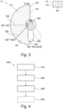
- Fig. 3 further shows that the multi-use control system 100 having the operating element 160 may be arranged at the switchgear module 10.
- the operating element 160 may be arranged at the outer surface of the switchgear module 10 or at the outer surface of the compartment for the switchgear module 10, so that the handle 160 may be pivotable from the exterior, and the other components such as the first and second rotating elements 110, 120 designed in the Geneva-like drive mechanism may be arranged inside the switchgear module 10 or inside the compartment for securing the switchgear module 10.
- the operating element 160 may pivot or rotate in two separate angular ranges including a first angular range 180, which may cover the 0°, 90° and 135° angular positions as the first group of angular positions 161, 162, 163, for switching the switchgear module 10 between the ON-, OFF- and/or TEST-modes and a second angular range 280, which may cover the 135° to 180° angular positions as the second group of angular positions 163, 164, for controlling the interlocking assembly to lock or release the switchgear module 10.
- a first angular range 180 which may cover the 0°, 90° and 135° angular positions as the first group of angular positions 161, 162, 163, for switching the switchgear module 10 between the ON-, OFF- and/or TEST-modes
- a second angular range 280 which may cover the 135° to 180° angular positions as the second group of angular positions 163, 164, for controlling the interlocking assembly to lock
- the operating element 160 may be designed to rotate continuously between the first angular range 180 and the second angular range 280, so that the switching mechanism and the interlocking mechanism for the switchgear module 10 may be transited seamlessly both in the counterclockwise and clockwise directions.
- the second group of angular positions of the handle 160 may further comprise a closed angular position 163 and an open angular position 164.
- the closed angular position may be designed as a turning angular position, at which the switchgear module 10 may still be secured to the compartment as shown in Fig. 1 (c) and Fig. 2 (c)
- the open angular position 164 may be configured to collide or interconnect with the interlocking element 200 at the interlocking pin 215 for releasing the switchgear module 10 from the compartment in a RELEASE-mode as shown in Fig. 1 (d) and Fig. 2 (d) .
- the open angular position 164 may be set as a 180° angular position.
- the sliding element 115 of the first rotating element 110 may be configured to collide with the interlocking element 200, via the interlocking pin 215, and to transmit the rotational motion of the first rotating element 110 to a translational motion of the interlocking element 200 for releasing the switchgear module 10, when the operating element 160 may rotate to the open 180° angular position 164.
- the Geneva-like drive mechanism for the first and second rotating elements 110, 120 via the sliding element 115 and the elongated opening 125 may transmit the angular position of the operating element 160 to the main switch inside the switchgear module 10. Beyond the turning angle 163, the transmission may be interrupted.
- the interlocking mechanism may be released and the switchgear module 10 may be brought into a releasing or moving position. If the operating element 160 may get turned in the opposite direction, the interlocking mechanism may first lock the switchgear module 10 in the compartment and then start to transmit the rotational motion of the operating element to the main switch being or connected to the second rotating element 120.
- the operating element 160 may start to rotate from the first 0° angular position 161, at which the switchgear module 10 may be secured in the compartment and operate in the ON-mode.
- the sliding element 115 of the first rotating element 110 may be arranged at the first closed position 1251 of the elongated opening 125.
- the first rotating element 110 may pivot about the first rotating axis passing through the proximal end 111 in a clockwise direction and the sliding element 115 may be guided to slide along the elongated opening 125 from the first closed end 1251 towards the second open end 1252.
- the rotation motion may be transmitted from the first rotating element 110 to the second rotating element 120, so that the second rotating element 120 that may be connected to the main switch of the switchgear module 10 may be driven to rotate in a second clockwise direction about the second rotational axis passing through the second rotating point 128.
- the second rotational axis may thus be in parallel, but not identical, to the first rotational axis.
- the sliding element 115 may further be guided to slide along the elongated opening 125 to the second open end 1252. As the rotational motion of the first rotating element 110 may still be transmitted or transferred to the second rotating element 120, the rotation of the coupled first and second rotating elements 110, 120 may be synchronized.
- the third 135° angular position 163 shown in Fig. 1 (c) and Fig. 2 (c) may also be set as the closed angular position for the interlocking mechanism which may follow or be transited to, but be separated from, the switching mechanism for the switchgear module 10.
- the connection between the first and second rotating elements 110, 120 may end, since the sliding element 115 may slide off the elongated opening 126.
- the rotational transmission between the first and second rotating elements 110, 120 may be interrupted.
- the mode of the operation of the switchgear module 10 may be kept at the TEST-mode. However, the switchgear module 10 may further be secured inside the compartment.
- the first rotating element 110 may rotate freely until the sliding element 115 of the first rotating element 110 may come into contact or collide with the interlocking element 200 at the interlocking pin 215.
- the interlocking element 200 may be a rocker switch.
- the rotational motion of the first rotating element 110 may be transmitted to the lineal, translational and/or rotational motion of the rocker switch 200, so that the control system may be in the RELEASE-mode to allow the switchgear module 10 releasable or withdrawable from the compartment.
- the operating element 160 may also rotate in the opposite direction to reverse the rotation of the first pivoting element 110 in the counterclockwise direction.
- the first rotating element 110 may not in contact with and interact with the interlocking element 200 after leaving the open 180° angular position in Fig. 1 (d) and Fig. 2 (d) , and the switchgear module 10 may be locked or secured inside the compartment again.
- the first rotating element 110 may freely rotate further until the sliding element 115 may interconnect to the second open end 1252 of the elongated opening 125 at the close angular position for the interlocking mechanism and the third 135° angular position 163 for the TEST-mode of the switchgear module 10, as shown in Fig. 1 (c) and Fig. 2 (c) .
- the rotation motion may be transmitted again between the first and second rotating elements 110, 120, the first and second rotating element 110, 120 may further be coupled and rotate synchronized to switch the switchgear module 10 between the various modes of operation, in particular, from the TEST-mode in Fig. 1 (c) and Fig. 2 (c) to the OFF-mode in Fig. 1 (b) and Fig. 2 (b) and further to the ON-mode in Fig. 1 (a) and Fig. 2(a) .
- the transition between the driving and non-driving may be performed within a continuous rotation by means of the single operating element 160 to enable two separate switching mechanisms, respectively under the coupled rotation of the driving first rotating element 110 and the driven second rotating element 120 and under the rotation of the freely rotatable first rotating element 110.
- the freely rotatable first rotating element may further be used as a driving part to interconnect or interact with the interlocking element 200 to actuate the interlocking mechanism requiring a linear force or movement.
- first and second rotating elements 110 and 120 may, respectively, be designed to be two flat parts that only need to be combined or connected with cost efficient parts such as screws and/or pins, the manufacturing costs for the compact control system 100 for the switchgear module 10 may be significantly reduced.
- Fig. 4 shows schematically a flow chart illustrating a method 400 for operating a switchgear module 10 by means of a multi-use control system 100.
- a first rotating element 110 is connected to an operating element 160 being pivotable between a plurality of angular positions comprising a first group of angular positions 161, 162, 163 and a second group of angular positions 163, 164.
- step 420 the sliding element 115 is interconnected with the elongated opening 125, guided to slide along the elongated opening 125, and a rotational motion is transmitted from the first rotating element 110 to the second rotating element 120 for switching the switchgear module 10 between the plurality of modes of operation, while rotating the operating element 160 between the first group of angular positions 161, 162, 163.
- step 430 the sliding element 115 is disconnected from the elongated opening 125 and the first rotating element 110 is allowed to transmit the rotational motion to the interlocking element 200 for securing or releasing the switchgear module 10, while rotating the operating element 160 between the second group of angular positions 163, 164.
- the method may further comprise the step 440, in which the operating element 160 may be rotated in an opposite direction for securing the switchgear module 10 to the compartment by disconnecting the first rotating element 110 from the interlocking element 200, interconnecting the sliding element 110 with the elongated opening 125 for transiting the controlling over the interlocking assembly to the controlling over the switching assembly, and guiding the sliding element 110 to slide along the elongated opening 125, and rotating the operating element 160 between the first group of angular positions 161, 162, 163 for switching the switchgear module 10 between the plurality of modes of operation.
Landscapes
- Switch Cases, Indication, And Locking (AREA)
Abstract
The invention relates to a multi-use control system (100) for a switchgear module (10) being switchable between a plurality of modes of operation, which comprises a first rotating element (110) with a sliding element (115), a second rotating element (120) with an elongated opening (125) and being connectable to the switchgear module and an interlocking element (200) for securing or releasing the switchgear module. The first rotating element is connectable to an operating element (160) being rotatable between a plurality of angular positions comprising a first group of angular positions (161, 162, 163) and a second group of angular positions (163, 164). The the sliding element (115) is configured to interconnect with the elongated opening (125) and transmit a rotational motion between the first and second rotating elements for switching the switchgear module for the first group of angular positions, and to interconnect with and transmit the rotational motion to the interlocking element for releasing the switchgear module for the second group of angular positions.
Description
- The present disclosure relates to industrial automation. In particular, the present disclosure relates to a multi-use control system for a switchgear module, a switchgear module comprising a multi-use control system and a method for operating a switchgear module by means of a multi-use control system.
- Switchgear technology is widely implemented in electrical power systems, such as industrial automation and robotic systems, in order to provide effective control and reliable protection for the embedded electrical components. In particular for low-voltage applications, switchgear modules may regulate power distribution within the electrical power systems, ensuring efficient operation and optimal management of electrical loads. Equipped with protective components such as circuit breakers and fuses, such switchgear modules may safeguard against overcurrent and short circuits, minimizing the risk of equipment damage or accidents. Further, these modules may offer flexibility in installation, expansion, and maintenance, for example for the the automation and robotic systems. It may thus be of great importance that these switchgear modules may be implemented and operated in a well-controlled manner.
- It may be seen as an objective of the invention to provide an improved control system for seamless operating a switchgear device with an optimized flexibility and reliability.
- The objective is achieved by the subject matter of the independent claims. The dependent claims, the following description and the drawings show embodiments of the invention.
- According to a first aspect of the present disclosure, a multi-use control system is provided for a switchgear module. The multi-use control system comprises a first rotating element that comprises a sliding element, a second rotating element, which comprises an elongated opening and is connectable to the switchgear module that is switchable between a plurality of modes of operation, and an interlocking element that is configured to secure the switchgear module to or release the switchgear module from a compartment. The first rotating element is connectable to an operating element that is rotatable between a plurality of angular positions comprising a first group of angular positions and a second group of angular positions.
- The sliding element is configured to interconnect with and slide along the elongated opening, and to transmit a rotational motion from the first rotating element to the second rotating element for switching the switchgear module between the plurality of modes of operation, when the operating element rotates between the first group of angular positions.
- Further, the sliding element is configured to disconnect from the elongated opening and to allow the first rotating element transmitting the rotational motion to the interlocking element for securing or releasing the switchgear module, when the operating element rotates between the second group of angular positions.
- When the operating element may pivot between the first group of angular positions for switching the modes of operation of the switchgear module, the first rotating element and the second rotating element may be coupled and interconnected with each other in a so-called internal Geneva-like drive mechanism by means of the interacting sliding element of the first rotating element and the elongated opening arranged at the second rotation element. As such, the first rotating element, the second rotating element and the operating element may form a switching assembly, which may perform a switching mechanism for the switchgear module, since the second rotating element may further be connected to a main switch of the switchgear module.
- In contrast, when the operating element may pivot between the second group of angular positions for securing or releasing the switchgear module, the first rotating element may come into contact or collide with the interlocking element and drive the interlocking element to move and/or rotate, for example to unlock the secured switchgear module inside the compartment. Hence, the first rotating element, the interlocking element and the operating element may form together an interlocking assembly, which may perform an interlocking mechanism for the switchgear module.
- In other words, the Geneva-like drive mechanism for the first and second rotating elements via the sliding element and the elongated opening may transmit the angular position of the operating element to the main switch inside the switchgear module. Beyond the turning angle, the transmission may be interrupted. By turning the operating element as the main handle of the control system further, the interlocking mechanism may be released and the switchgear module may be brought into a releasing or moving position. If the operating element may get turned in the opposite direction, the interlocking mechanism may first lock the switchgear module in the compartment and then start to transmit the rotational motion of the operating element to the main switch being or connected to the second rotating element.
- The control system may be designed to allow separate controlling over the switching assembly for the switching mechanism of the switchgear module or over the interlocking assembly for the interlocking mechanism of the switchgear module by means of the internal Geneva-like drive mechanism between the first and second rotating elements and the additionally arranged interlocking system. Further the control system may be designed to allow a seamless transition between the switching mechanism and the interlocking mechanism.
- For example, the compartment may be a housing, in which the switchgear module may be placed or mounted, so that the switchgear module may be operated under a safety condition. The switchgear module may be released or detached from the compartment while not being operated. Hence, the switchgear module may be designed as a withdrawable switchgear module. In particular, the withdrawable switchgear module may be a low-voltage switchgear module.
- According to an embodiment, the first rotating element may be designed to be a rotating lever arm that comprises a proximal end and a distal end.
- The rotating lever arm may be designed to be elongated rod-shaped extending between the proximal end and the distal end. As the rotating lever, the first rotating element may exercise a force to drive the connected second rotating element to rotate and thus transmit the rotational motion, when the operating element may rotate between the first group of angular positions for switching the modes of operation of the switchgear module.
- According to another embodiment, the sliding element may be arranged at the distal end of the first rotating element.
- Alternatively or additionally, the sliding element may be arranged between the proximal end and the distal end of the first rotating element or the rotating lever arm. Preferably, the sliding element may be arranged closer to the distal end than the proximal end to ease the transition of the rotational motion of the rotating lever arm to the second rotating element via the sliding element being guided along the through opening of the second rotating element.
- According to another embodiment, the multi-use control system may further comprise the operating element, which may be a handle that is configured to connect to the first rotating element at the proximal end via a shaft.
- The operating element may be configured to control the switching assembly to switch the switchgear module between the plurality of modes of operation, when pivoting between the first group of angular positions, and to control the interlocking assembly to secure or release the switchgear module, when pivoting between the second group of angular positions.
- The operating element may be arranged on the front of the switchgear module. Further, the operating element and the shaft may be connected to the first rotating element at the proximal end of the first rotating element, so that the driving force may be transmitted from the handle to the first rotating element.
- According to another embodiment, the first rotating element may be configured to rotate about a first rotational axis passing through the proximal end of the first rotating element, when the operating element may rotate between the plurality of angular positions.
- The first rotational axis of the first rotating element may be vertical to the elongated rotating lever arm. The proximal end of the first rotating element may thus be a first rotating point. Since the operating element may be connected to the first rotating element via the shaft at the proximal end, the operating element and the connecting shaft may also be configured to rotate about the same first rotational axis.
- According to another embodiment, the sliding element may be a sliding pin, a sliding clamp or a sliding screw.
- According to another embodiment, the elongated opening may comprise a first end and a second end. The sliding element of the first rotating element may be configured to be guided to slide between the first end and second end of the elongated opening, and to drive the second rotating element to rotate about a second rotational axis, when the operating element may rotate between the first group of angular positions.
- The elongated opening may be designed as a slot or a rail for the sliding element and configured to guide the sliding element to move or slide along the rail, after the sliding element may be coupled or connected to to the elongated opening.
- According to another embodiment, the second rotational axis of the second rotating element may be arranged in parallel to the first rotational axis of the first rotating element.
- The second rotating element may also comprise an elongated shape extending from a second rotating point of the second rotating element may be arranged, to the second end of the elongated opening of the second rotating element.
- According to another embodiment, the first end of the second rotating element may be a closed end and the second end of the elongated opening may be an open end. The sliding element may be configured to slide off the elongated opening at the open end, when the operating element may rotate between the second group of angular positions.
- For example, when the operating element may drive the first rotation element to rotate or pivot in a direction, preferably in a clockwise direction for a transition from the switching mechanism towards the interlocking mechanism, the sliding element may be configured to slide from the first, closed end of the elongated opening to the second, open end of the elongated opening, at which the sliding element may further slide off the elongated opening. The sliding of the sliding element may be configured to convert the rotational motion of the first rotating element into the rotational motion of the second rotation element about the second rotating axis passing through the second rotation point of the second rotation element. The second rotation point may be arranged at the opposite end of the elongated second rotating element to the second, open end of the elongated opening. Alternatively, the second rotation point may be arranged between the opposite end of the second rotating element and the second, open end of elongated opening.
- Driven by the transmitted rotational force or motion, the second rotating element may rotate in a corresponding direction or a clockwise direction.
- According to another embodiment, the plurality of modes of operation of the switchgear module may comprise a first mode of operation, a second mode of operation and/or a third mode of operation. The first group of angular positions of the operating element may comprise a first angular position, which may be configured to interconnect with the first mode of operation of the switchgear module, and a second angular position, which may be configured to interconnect with the second mode of operation of the switchgear module, and/or a third angular position, which may be configured to interconnect with the third mode of operation of the switchgear module.
- According to another embodiment, the first mode of operation of the switchgear module may be an ON-mode, the second mode of operation of the switchgear module may be an OFF-mode, and/or the third mode of operation of the switchgear module may be an TEST-mode.
- The first angular position of the operating element may be a 0° angular positon, the second angular position of the operating element may be a 90° angular positon or a 135° angular position and/or the third angular position of the operating element may be a 135° angular positon.
- In the ON-mode, the switchgear module may be inserted or secured in the compartment, a main switch of the switchgear module may be closed, the main circuit and control circuit of the switchgear module may be connected. In the OFF-mode, the switchgear module may be inserted or secured in the compartment, the main switch of the switchgear module may be open, the main circuit and the control circuit of the switchgear module may be disconnected. A padlocking for the switchgear module may be provided for the OFF-mode. In the TEST-mode, the switchgear module may be inserted or secured in the compartment, the main switch of the switchgear module may be open, the main circuit of the switchgear module may be disconnected. A padlocking for the switchgear module may be provided for the TEST-mode. Compared to the OFF-mode, the additional TEST-mode may be designed to allow the control circuit being still connected.
- According to another embodiment, the second group of angular positions of the operating element may comprise a closed angular position, which may be a 90° angular position or a 135° angular position, and an open angular position, which may be a 180° angular position.
- According to another embodiment, the sliding element may be configured to collide with the interlocking element and to transmit the rotational motion of the first rotating element to a translational motion of the interlocking element for releasing the switchgear module, when the operating element may rotate to the open angular positions.
- For example, the interlocking element may be a rocker switch for securing the switchgear module inside the compartment. The interlocking element may comprise an interlocking pin being arranged at an end of the interlocking element adjacent to the first rotation element. After the sliding element may slide off the elongated opening, the control system may be configured to allow a collision between the sliding element and the interlocking pin at the 180° angular position for a RELEASE-mode, in which the switchgear module may be released or withdrawable from the compartment.
- The closed angular position may correspond to an initial position for the switchgear module being locked or secured inside the compartment. When the operating element may rotate between the closed and open angular positions, the first rotation element may rotate freely for a while without interacting with both the second rotating element and the interlocking element until reaching the closed or open angular position.
- By rotating the operating element in an opposite direction to reverse the rotation direction of the first pivoting element, for example in a counterclockwise direction, the first rotating element may disconnect from the interlocking system to allow the interlocking pin moving and/or rotating back to the initial position as the closed, locking position, so that the switchgear module may be secured in the compartment again.
- The 90° or 135° angular position may be a turning angular point, by which a transition between the switching mechanism and the interlocking mechanism may take place by rotating the operating element across the turning angular point.
- The multi-use control system comprising the various components comprising the first and second rotating elements following a Geneva-like drive mechanism and the interlocking element may allow the separation and the transition of the switching and interlocking mechanisms for the switchgear module in a continuous manner using the single operating handle. In other words, the transition from the controlling over the switching assembly to the controlling over the interlocking assembly in the continuous direction may be performed as a result of the sliding of the sliding element of the first rotating element off the elongated opening of the second rotating element and the collision of the first rotating element with the interlocking element.
- Further, the single operating element or handle may be arranged on the front of the switchgear module and fulfill two separate functions safely and reliably: the switching of the switching device or the main switching device into all its possible positions, such as the ON-, OFF-, TEST-positions, which may be set by various angular positions covering a first angular rage of 0°, 90° and/or 135° angular positions, and the locking or releasing the entire switchgear module inside its compartment by transmitting the rotary motion of the main handle to the interlocking element via the first rotating element, when rotating covering the second angular range or the second groups of angular positions. This mechanism may ensure that the main switching assembly may be switched to the OFF-mode and/or the TEST-mode, before the switchgear module may be released. Once the switchgear module may be secured to into the compartment again, the mechanism may ensure that the switching assembly may first be switched to the TEST-mode and/or OFF-mode and then to the operating ON-mode. In particular, in order to meet the first functional requirement, the rotary motion of the operating handle on the switchgear module front may be translated to the main switching assembly via the first and second rotating elements interconnecting each other in the Geneva-like drive mechanism, so that the turning angles of the handle and the sense of the rotation of the switching assembly for the respective modes of operation may correspond to each other.
- Alternatively, for example, the first angular position, the second angular position and/or the third angular position may be any angular position between 0° and 180° arranged in a sequence along the same direction for pivoting the operating element and the respective first and second pivoting elements being coupled with each other. As such, the predefined turning angular position being the second or third angular position may be arranged between 0° and 180°. Further, after the transition from the switching mechanism to the interlocking mechanism for the switchgear module, the pivoting element may drive the first pivoting element to the open angular position for releasing the switchgear module, which may be arranged, alternatively to the 180° angular position, between the turning angular position and the 180° angular position, or at a larger angular position between 180° to 360° angular positions, preferably between 180° to 270° angular positions, preferably between 180° or 225° angular positions.
- According to a second aspect, a switchgear module is provided, which comprises a multi-use control system. The switchgear module is a low-voltage switchgear module.
- The switchgear module may be a low-voltage switchgear module, which may be configured to operate at a voltage range between 0 V and 1000 V. Alternatively, the switchgear module may be a medium-voltage or high-voltage switchgear module. And the multi-use control system may be integrated in the medium-voltage or high-voltage switchgear module.
- Further, a use of a multi-use control system for a switchgear module may be provided for a safe operation of the switchgear module in an electrical power system, for example in an automatic system or a robotic system.
- With the first and second rotating elements, respectively, being designed to be two flat parts that only need to be combined or connected with cost efficient parts such as screws and/or pins, the manufacturing costs for the
compact control system 100 for the switchgear module may be significantly reduced. - According to a third aspect, a method for operating a switchgear module by means of a multi-use control system is provided. The method comprises the following steps: connecting a first rotating element to an operating element that is rotatable between a plurality of angular positions comprising a first group of angular positions and a second group of angular positions; interconnecting the sliding element with the elongated opening, guiding the sliding element to slide along the elongated opening, and transmitting a rotational motion from the first rotating element to the second rotating element for switching the switchgear module between the plurality of modes of operation, while rotating the operating element between the first group of angular positions; disconnecting the sliding element from the elongated opening and allowing the first rotating element transmitting the rotational motion to the interlocking element for securing or releasing the switchgear module, while pivoting the operating element between the second group of angular positions.
- Additionally, the method may further comprise the step of rotating the operating element in an opposite direction for securing the switchgear module to the compartment by disconnecting the first rotating element from the interlocking element, interconnecting the sliding element with the elongated opening transiting the controlling over the interlocking assembly to the controlling over the switching assembly and guiding the sliding element to slide along the elongated opening, and rotating the operating element between the first group of angular positions for switching the switchgear module between the plurality of modes of operation.
- There may be provided a computer program that comprises machine-readable instructions that, when executed by one or more computers and/or compute instances, cause the one or more computers and/or compute instances to perform a method for operating a switchgear module by means of a multi-use control system in an automation or robotic system.
- There may be provided a non-transitory machine-readable data carrier and/or a download product with the computer program. A download product is an instance of the computer program that may be sold and downloaded online for immediate fulfilment in lieu of physically shipping a machine-readable data carrier.
- There may be provided one or more computers and/or compute instances with the computer program comprising machine-readable instructions that, when executed by one or more computers and/or compute instances, cause the one or more computers and/or compute instances to perform a method for operating a switchgear module by means of a multi-use control system in an electrical power system including an automation system and a robotic system, and/or with the machine-readable data carrier and/or download product with the computer program.
- The method may be at least partly computer-implemented, and may be implemented in software or in hardware, or in software and hardware. Further, the method may be carried out by computer program instructions running on means that provide data processing functions. The data processing means may be a suitable computing means, such as an electronic control module etc., which may also be a distributed computer system. The data processing means or the computer, respectively, may comprise one or more of a processor, a memory, a data interface, or the like.
- It should be noted that the above examples may be combined with each other irrespective of the aspect involved. Accordingly, the method may be combined with structural features and, likewise, the apparatus and the system may be combined with features described above with regard to the method.
- These and other aspects will be apparent from and elucidated with reference to the embodiments as per the drawings described hereinafter.
- Examples of the disclosure will be described in the following with reference to the following drawings.
- Fig. 1 (a) to (d)
- shows schematically an example of a multi-use control system for a switchgear module in a perspective view according to the present disclosure;
- Fig. 2 (a) to (d)
- shows schematically an example of a multi-use control system for a switchgear module in a simplified side view according to the present disclosure;
- Fig. 3
- shows schematically an example of a switchgear module according to the present disclosure;
- Fig. 4
- shows schematically a flow chart illustrating a method for operating a switchgear module by means of a multi-use control system according to the present disclosure.
- The figures are merely schematic representations and serve only to illustrate examples of the disclosure. Identical or equivalent elements are in principle provided with the same reference signs.
-
Fig. 1 andFig. 2 show schematically an example of amulti-use control system 100 for aswitchgear module 10, which may be a low-voltage switchgear module, respectively, in a perspective view and in a simplified side view. Themulti-use control system 100 comprises a firstrotating element 110, a secondrotating element 120 and an interlocking element 220 and anoperating element 160 which is also shown inFig. 3 . - The first
rotating element 110 comprises a slidingelement 115, which may be a sliding pin as shown inFig. 1 andFig. 2 . Further, the firstrotating element 110 may be designed to be a rotating lever arm comprising aproximal end 111 and adistal end 112. The slidingelement 115 is arranged at thedistal end 112 of the firstrotating element 110. The firstrotating element 110 is connectable to theoperating element 160 which may be designed as a handle and is rotatable between a plurality of angular positions comprising a first group ofangular positions angular positions Fig. 3 . InFig. 1 andFig. 2 , the firstrotating element 110 is connected with theoperating element 160 and theshaft 150 at theproximal end 111. The firstrotating element 110 may be configured to rotate about a first rotational axis passing through theproximal end 111 of the firstrotating element 110, along with theshaft 150 and theoperating element 160, when theoperating element 160 may rotate between the plurality of angular positions. - The second
rotating element 120 comprises anelongated opening 125 or a slot and may be connectable to theswitchgear module 10 that is switchable between a plurality of modes of operation. Further, theelongated opening 125 comprises afirst end 1251 and asecond end 1252. While thefirst end 1251 of the secondrotating element 120 may be a closed end, which may also be arranged at a second distal end of the secondrotating element 120, thesecond end 1252 of theelongated opening 125 may be an open end being arranged in the middle region of the elongated secondrotating element 120. - The sliding
element 115 of the firstrotating element 110 may be configured to interconnect with and slide along theelongated opening 125 and to transmit a rotational motion from the firstrotating element 110 to the secondrotating element 120 for switching theswitchgear module 10 between the plurality of modes of operation, when theoperating element 160 may rotate between the first group ofangular positions Fig. 1 (a) to (c) andFig. 2 (a) to (c) . In other words, the slidingelement 115 may be configured to be guided to slide between thefirst end 1251 and thesecond end 1252 of theelongated opening 125 and to drive the secondrotating element 120 to rotate about a second rotational axis, when theoperating element 160 may rotate between the first group ofangular positions - The second
rotating element 120 may further comprise a secondrotating point 128. The second rotational axis of the secondrotating element 120 may be designed to pass through the secondrotating point 128. The second rotational axis of the secondrotating element 120 may be designed to be a parallel, but not identical, rotational axis to the first rational axis of the firstrotating element 120. - The second
rotating element 120 may further connect to the main switch of theswitchgear module 10, so that the secondrotating element 120 may rotate for switching theswitchgear module 10 between the modes of operation. The plurality of modes of operation of theswitchgear module 10 may comprise a first mode of operation, as shown inFig. 1 (a) andFig. 2(a) , a second mode of operation, as shown inFig. 1 (b) andFig. 2(b) , and a third mode of operation, as shown inFig. 1 (c) andFig. 2(c) . The first mode of operation may be an ON-mode, in which the switchgear module may be switched to in a normal operation mode, while the second mode of operation may be an OFF-mode, in which theswitchgear module 10 may be switched off or completely turned off. Also, in the ON-mode, theswitchgear module 10 may be inserted or secured in the compartment, the main switch of theswitchgear module 10 may be closed, the main circuit and control circuit of the switchgear module may be connected. In the OFF-mode, theswitchgear module 10 may be inserted or secured in the compartment, the main switch of the switchgear module may be open, the main circuit and the control circuit of the switchgear module may be disconnected. In the TEST-mode, theswitchgear module 10 may be inserted or secured in the compartment, the main switch of the switchgear module may be open, the main circuit of the switchgear module may be disconnected. Compared to the OFF-mode, the additional TEST-mode may be designed to allow the control circuit being still connected. - The first group of angular positions of the
operating element 160 may comprise a firstangular position 161 or a 0° angular position, which may be configured to interconnect with the first ON-mode of operation of theswitchgear module 10 as shown inFig. 1(a) andFig. 2(a) , a secondangular position 162 or a 90° angular position, configured to interconnect with the second mode of operation of theswitchgear module 10, as shown inFig. 1(b) andFig. 2(b) , and a thirdangular position 163 or a 135° angular position, which may be configured to interconnect with the third TEST-mode of operation of theswitchgear module 10 as shown inFig. 1(c) andFig. 2(c) . - In order to disconnect the first and second
rotating elements rotating element 110 to the secondrotating element 120, the slidingelement 115 may be configured to slide off theelongated opening 125 at theopen end 1252, when theoperating element 160 may further rotate till the third 135°angular position 163 as a turning angular position, at the a transition between the switching mechanism and the interlocking mechanism of theswitchgear module 10 may occur. - The interlocking
element 200 may comprise aninterlocking pin 215 and configured to secure theswitchgear module 10 to or release theswitchgear module 10 from a compartment for safely operating theswitchgear module 10. The slidingelement 115 may be configured to disconnect from theelongated opening 125 and to allow the firstrotating element 110 transmitting the rotational motion to the interlockingelement 200 for securing or releasing theswitchgear module 10, when theoperating element 160 rotates between the second group ofangular positions element 200 may be designed to be a rocker switch. The interlockingpin 215 may be provided at an freestanding end of the rocker switch adjacent to the firstrotating element 110, so that the slidingelement 115 may come into contact or collide with the interlockingpin 215 of the interlockingelement 200 when rotating with theoperating element 160 to an angular position ofFig. 1 (d) andFig. 2 (d) , at which theswitchgear module 10 may be withdrawable from the compartment. - The second group of angular positions of the
operating element 160 may comprise a closed angular position, which is a 135°angular position 163 as shown inFig. 1 (c) andFig. 2 (c) , and an open angular position, which is a 180°angular position 164 as shown inFig. 1 (d) andFig. 2 (d) and may be configured to allow theswitchgear module 10 being released from the compartment in a RELEASE-mode of thecontrol system 100. -
Fig. 3 further shows that themulti-use control system 100 having the operatingelement 160 may be arranged at theswitchgear module 10. For example, theoperating element 160 may be arranged at the outer surface of theswitchgear module 10 or at the outer surface of the compartment for theswitchgear module 10, so that thehandle 160 may be pivotable from the exterior, and the other components such as the first and secondrotating elements switchgear module 10 or inside the compartment for securing theswitchgear module 10. Theoperating element 160 may pivot or rotate in two separate angular ranges including a firstangular range 180, which may cover the 0°, 90° and 135° angular positions as the first group ofangular positions switchgear module 10 between the ON-, OFF- and/or TEST-modes and a secondangular range 280, which may cover the 135° to 180° angular positions as the second group ofangular positions switchgear module 10. Further, theoperating element 160 may be designed to rotate continuously between the firstangular range 180 and the secondangular range 280, so that the switching mechanism and the interlocking mechanism for theswitchgear module 10 may be transited seamlessly both in the counterclockwise and clockwise directions. - In
Fig. 3 , the second group of angular positions of thehandle 160 may further comprise a closedangular position 163 and an openangular position 164. The closed angular position may be designed as a turning angular position, at which theswitchgear module 10 may still be secured to the compartment as shown inFig. 1 (c) andFig. 2 (c) , and the openangular position 164 may be configured to collide or interconnect with the interlockingelement 200 at the interlockingpin 215 for releasing theswitchgear module 10 from the compartment in a RELEASE-mode as shown inFig. 1 (d) andFig. 2 (d) . The openangular position 164 may be set as a 180° angular position. - As shown in
Fig. 1 (d) andFig. 2 (d) , the slidingelement 115 of the firstrotating element 110 may be configured to collide with the interlockingelement 200, via theinterlocking pin 215, and to transmit the rotational motion of the firstrotating element 110 to a translational motion of the interlockingelement 200 for releasing theswitchgear module 10, when theoperating element 160 may rotate to the open 180°angular position 164. - The Geneva-like drive mechanism for the first and second
rotating elements element 115 and theelongated opening 125 may transmit the angular position of theoperating element 160 to the main switch inside theswitchgear module 10. Beyond theturning angle 163, the transmission may be interrupted. By turning theoperating element 160 as the main handle of the control system further, the interlocking mechanism may be released and theswitchgear module 10 may be brought into a releasing or moving position. If theoperating element 160 may get turned in the opposite direction, the interlocking mechanism may first lock theswitchgear module 10 in the compartment and then start to transmit the rotational motion of the operating element to the main switch being or connected to the secondrotating element 120. - In particular, as shown in
Fig. 1 (a) to Fig. 1 (d) , theoperating element 160 may start to rotate from the first 0°angular position 161, at which theswitchgear module 10 may be secured in the compartment and operate in the ON-mode. The slidingelement 115 of the firstrotating element 110 may be arranged at the firstclosed position 1251 of theelongated opening 125. - By rotating the
operating element 160 for switching theswitchgear module 10 to the OFF-mode at the second 90°angular position 162, as shown inFig. 1 (b) andFig. 2 (b) , the firstrotating element 110 may pivot about the first rotating axis passing through theproximal end 111 in a clockwise direction and the slidingelement 115 may be guided to slide along theelongated opening 125 from the firstclosed end 1251 towards the secondopen end 1252. In this way, the rotation motion may be transmitted from the firstrotating element 110 to the secondrotating element 120, so that the secondrotating element 120 that may be connected to the main switch of theswitchgear module 10 may be driven to rotate in a second clockwise direction about the second rotational axis passing through the secondrotating point 128. The second rotational axis may thus be in parallel, but not identical, to the first rotational axis. - By further rotating the
operating element 160 for switching theswitchgear module 10 to the TEST-mode at the third 135°angular position 163, as shown inFig. 1 (c) andFig. 2 (c) , the slidingelement 115 may further be guided to slide along theelongated opening 125 to the secondopen end 1252. As the rotational motion of the firstrotating element 110 may still be transmitted or transferred to the secondrotating element 120, the rotation of the coupled first and secondrotating elements - The third 135°
angular position 163 shown inFig. 1 (c) andFig. 2 (c) may also be set as the closed angular position for the interlocking mechanism which may follow or be transited to, but be separated from, the switching mechanism for theswitchgear module 10. By further rotating theoperating element 160 over the 135°angular position 163, the connection between the first and secondrotating elements element 115 may slide off the elongated opening 126. The rotational transmission between the first and secondrotating elements switchgear module 10 may be kept at the TEST-mode. However, theswitchgear module 10 may further be secured inside the compartment. - Until further rotating the
operating element 160 for releasing theswitchgear module 10 at the open 180°angular position 164, as shown inFig. 1 (d) andFig. 2 (d) , the firstrotating element 110 may rotate freely until the slidingelement 115 of the firstrotating element 110 may come into contact or collide with the interlockingelement 200 at the interlockingpin 215. The interlockingelement 200 may be a rocker switch. The rotational motion of the firstrotating element 110 may be transmitted to the lineal, translational and/or rotational motion of therocker switch 200, so that the control system may be in the RELEASE-mode to allow theswitchgear module 10 releasable or withdrawable from the compartment. - Additionally, the
operating element 160 may also rotate in the opposite direction to reverse the rotation of thefirst pivoting element 110 in the counterclockwise direction. The firstrotating element 110 may not in contact with and interact with the interlockingelement 200 after leaving the open 180° angular position inFig. 1 (d) andFig. 2 (d) , and theswitchgear module 10 may be locked or secured inside the compartment again. The firstrotating element 110 may freely rotate further until the slidingelement 115 may interconnect to the secondopen end 1252 of theelongated opening 125 at the close angular position for the interlocking mechanism and the third 135°angular position 163 for the TEST-mode of theswitchgear module 10, as shown inFig. 1 (c) andFig. 2 (c) . As in the switching mechanism the rotation motion may be transmitted again between the first and secondrotating elements rotating element switchgear module 10 between the various modes of operation, in particular, from the TEST-mode inFig. 1 (c) andFig. 2 (c) to the OFF-mode inFig. 1 (b) andFig. 2 (b) and further to the ON-mode inFig. 1 (a) andFig. 2(a) . - By using the Geneva-like drive mechanism with the first and second
rotating elements single operating element 160 to enable two separate switching mechanisms, respectively under the coupled rotation of the driving firstrotating element 110 and the driven secondrotating element 120 and under the rotation of the freely rotatable firstrotating element 110. Further, the freely rotatable first rotating element may further be used as a driving part to interconnect or interact with the interlockingelement 200 to actuate the interlocking mechanism requiring a linear force or movement. - As the first and second
rotating elements compact control system 100 for theswitchgear module 10 may be significantly reduced. -
Fig. 4 shows schematically a flow chart illustrating amethod 400 for operating aswitchgear module 10 by means of amulti-use control system 100. - In
step 410, a firstrotating element 110 is connected to anoperating element 160 being pivotable between a plurality of angular positions comprising a first group ofangular positions angular positions - In
step 420, the slidingelement 115 is interconnected with theelongated opening 125, guided to slide along theelongated opening 125, and a rotational motion is transmitted from the firstrotating element 110 to the secondrotating element 120 for switching theswitchgear module 10 between the plurality of modes of operation, while rotating theoperating element 160 between the first group ofangular positions - In
step 430, the slidingelement 115 is disconnected from theelongated opening 125 and the firstrotating element 110 is allowed to transmit the rotational motion to the interlockingelement 200 for securing or releasing theswitchgear module 10, while rotating theoperating element 160 between the second group ofangular positions - Additionally, the method may further comprise the
step 440, in which theoperating element 160 may be rotated in an opposite direction for securing theswitchgear module 10 to the compartment by disconnecting the firstrotating element 110 from the interlockingelement 200, interconnecting the slidingelement 110 with theelongated opening 125 for transiting the controlling over the interlocking assembly to the controlling over the switching assembly, and guiding the slidingelement 110 to slide along theelongated opening 125, and rotating theoperating element 160 between the first group ofangular positions switchgear module 10 between the plurality of modes of operation. - While the invention has been illustrated and described in detail in the drawings and foregoing description, such illustration and description are to be considered illustrative or exemplary and not restrictive; the invention is not limited to the disclosed embodiments. Other variations to the disclosed embodiments can be understood and effected by those skilled in the art and practising the claimed invention, from a study of the drawings, the disclosure, and the appended claims. In the claims, the word "comprising" does not exclude other elements, and the indefinite article "a" or "an" does not exclude a plurality. A single processor or controller or other unit may fulfil the functions of several items recited in the claims. The mere fact that certain measures are recited in mutually different dependent claims does not indicate that a combination of these measures cannot be used to advantage. Any reference signs in the claims should not be construed as limiting the scope.
-
- 10
- switchgear module
- 100
- multi-use control system
- 110
- first rotating element
- 111
- proximal end
- 112
- distal end
- 115
- sliding element
- 120
- second rotating element
- 125
- elongated opening
- 1251
- first end of elongated opening
- 1252
- second end of elongated opening
- 128
- second rotating point of second rotating element
- 150
- shaft
- 160
- opering element or handle
- 161
- first angular position
- 162
- second angular position
- 163
- third angular position / closed angular position
- 164
- open angular position
- 180
- first angular range
- 200
- interlocking element
- 215
- interlocking pin
- 280
- second angular range
- 400
- method for operating a switchgear module
- 410
- step of connecting first rotating element to operating element
- 420
- step of interconnecting sliding element with elongated opening, guiding sliding element to slide along elongated opening, and transmitting a rotational motion from first rotating element to second rotating element
- 430
- step of disconnecting sliding element from elongated opening and allowing first rotating element transmitting the rotational motion to the interlocking element
- 440
- step of rotating the operating element in an opposite direction
Claims (15)
- Multi-use control system (100) for a switchgear module (10), comprising:a first rotating element (110) comprising a sliding element (115),a second rotating element (120) comprising an elongated opening (125) and being connectable to the switchgear module (10) which is switchable between a plurality of modes of operation, andan interlocking element (200), configured to secure the switchgear module (10) to or release the switchgear module (10) from a compartment;wherein the first rotating element (110) is connectable to an operating element (160) being rotatable between a plurality of angular positions comprising a first group of angular positions (161, 162, 163) and a second group of angular positions (163, 164);wherein the sliding element (115) is configured to interconnect with and slide along the elongated opening (125), and to transmit a rotational motion from the first rotating element (110) to the second rotating element (120) for switching the switchgear module (10) between the plurality of modes of operation, when the operating element (160) rotates between the first group of angular positions (161, 162, 163);wherein the sliding element (115) is configured to disconnect from the elongated opening (125) and to allow the first rotating element (110) transmitting the rotational motion to the interlocking element (200) for securing or releasing the switchgear module (10), when the operating element (160) rotates between the second group of angular positions (163, 164).
- The multi-use control system (100) according to claim 1,
wherein the first rotating element (110) is designed to be a rotating lever arm comprising a proximal end (111) and a distal end (112). - The multi-use control system (100) according to claim 2,
wherein the sliding element (115) is arranged at the distal end (112) of the first rotating element (110). - The multi-use control system (100) according to claim 2 or 3, further comprising:the operating element (160);wherein the operating element (160) is a handle, configured to connect to the first rotating element (110) at the proximal end (111) via a shaft (150).
- The multi-use control system (100) according to one of the preceding claims,
wherein the first rotating element (110) is configured to rotate about a first rotational axis passing through the proximal end (111) of the first rotating element (110), when the operating element (160) rotates between the plurality of angular positions. - The multi-use control system (100) according to one of the preceding claims,
wherein the sliding element (115) is a sliding pin, a sliding clamp or a sliding screw. - The multi-use control system (100) according to one of the preceding claims,wherein the elongated opening (125) comprises a first end (1251) and a second end (1252);wherein the sliding element (115) of the first rotating element (110) is configured to be guided to slide between the first end (1251) and second end (1252) of the elongated opening (125), and to drive the second rotating element (120) to rotate about a second rotational axis, when the operating element (160) rotates between the first group of angular positions (161, 162, 163).
- The multi-use control system (100) according to claim 7,
wherein the second rotational axis of the second rotating element (120) is arranged in parallel to the first rotational axis of the first rotating element (110). - The multi-use control system (100) according to claim 7 or 8,wherein the first end (1251) of the second rotating element (120) is a closed end and the second end (1252) of the elongated opening (125) is an open end;wherein the sliding element (115) is configured to slide off the elongated opening (125) at the open end (1252), when the operating element (160) rotates between the second group of angular positions (163, 164).
- The multi-use control system (100) according to one of the preceding claims,wherein the plurality of modes of operation of the switchgear module (10) comprises a first mode of operation, a second mode of operation and/or a third mode of operation;wherein the first group of angular positions of the operating element (160) comprises a first angular position (161), configured to interconnect with the first mode of operation of the switchgear module (10), and a second angular position (162), configured to interconnect with the second mode of operation of the switchgear module (10), and/or a third angular position (163), configured to interconnect with the third mode of operation of the switchgear module (10).
- The multi-use control system (100) according to claim 10,wherein the first mode of operation of the switchgear module (10) is an ON-mode, the second mode of operation of the switchgear module is an OFF-mode, and/or the third mode of operation of the switchgear module is an TEST-mode;wherein the first angular position (161) of the operating element (160) is a 0° angular positon, the second angular position (162) of the operating element is a 90° angular positon or a 135° angular position and/or the third angular position (163) of the operating element is a 135° angular positon.
- The multi-use control system (100) according to one of the preceding claims,
wherein the second group of angular positions of the operating element (160) comprises a closed angular position, which is a 90° angular position or a 135° angular position, and an open angular position, which is a 180° angular position (164). - The multi-use control system (100) according to one of the preceding claims,
wherein the sliding element (115) is configured to collide with the interlocking element (200) and to transmit the rotational motion of the first rotating element (110) to a translational motion of the interlocking element (200) for releasing the switchgear module (10), when the operating element (160) rotates to the open angular positions (164). - Switchgear module (10) comprising a multi-use control system (100) according to one of the preceding claims 1 to 13,
wherein the switchgear module (10) is a low-voltage switchgear module. - Method (400) for operating a switchgear module (10) by means of a multi-use control system (100), comprising the steps of:connecting (410) a first rotating element (110) to an operating element (160) being rotatable between a plurality of angular positions comprising a first group of angular positions (161, 162, 163) and a second group of angular positions (163, 164);interconnecting (420) the sliding element (115) with the elongated opening (125), guiding the sliding element (115) to slide along the elongated opening (125), and transmitting a rotational motion from the first rotating element (110) to the second rotating element (120) for switching the switchgear module (10) between the plurality of modes of operation, while rotating the operating element (160) between the first group of angular positions (161, 162, 163);disconnecting (430) the sliding element (115) from the elongated opening (125) and allowing the first rotating element (110) transmitting the rotational motion to the interlocking element (200) for securing or releasing the switchgear module (10), while rotating the operating element (160) between the second group of angular positions (163, 164).
Priority Applications (1)
| Application Number | Priority Date | Filing Date | Title |
|---|---|---|---|
| EP23188074.1A EP4498397A1 (en) | 2023-07-27 | 2023-07-27 | Multi-use control system for switchgear module with guided sliding element |
Applications Claiming Priority (1)
| Application Number | Priority Date | Filing Date | Title |
|---|---|---|---|
| EP23188074.1A EP4498397A1 (en) | 2023-07-27 | 2023-07-27 | Multi-use control system for switchgear module with guided sliding element |
Publications (1)
| Publication Number | Publication Date |
|---|---|
| EP4498397A1 true EP4498397A1 (en) | 2025-01-29 |
Family
ID=87517343
Family Applications (1)
| Application Number | Title | Priority Date | Filing Date |
|---|---|---|---|
| EP23188074.1A Pending EP4498397A1 (en) | 2023-07-27 | 2023-07-27 | Multi-use control system for switchgear module with guided sliding element |
Country Status (1)
| Country | Link |
|---|---|
| EP (1) | EP4498397A1 (en) |
Citations (4)
| Publication number | Priority date | Publication date | Assignee | Title |
|---|---|---|---|---|
| US3793493A (en) * | 1972-08-21 | 1974-02-19 | Ite Imperial Corp | Draw out circuit breaker and compartment interlock and secondary contact actuation |
| US4105878A (en) * | 1977-01-17 | 1978-08-08 | Mcgraw-Edison Company | Vacuum interrupter and disconnect combination |
| US20010022262A1 (en) * | 2000-03-17 | 2001-09-20 | Rane Mahesh Jaywant | Locking arrangement for circuit breaker draw-out mechanism |
| US20180090913A1 (en) * | 2016-09-26 | 2018-03-29 | Bethel Idiculla Johnson | Medium voltage switchgear enclosure |
-
2023
- 2023-07-27 EP EP23188074.1A patent/EP4498397A1/en active Pending
Patent Citations (4)
| Publication number | Priority date | Publication date | Assignee | Title |
|---|---|---|---|---|
| US3793493A (en) * | 1972-08-21 | 1974-02-19 | Ite Imperial Corp | Draw out circuit breaker and compartment interlock and secondary contact actuation |
| US4105878A (en) * | 1977-01-17 | 1978-08-08 | Mcgraw-Edison Company | Vacuum interrupter and disconnect combination |
| US20010022262A1 (en) * | 2000-03-17 | 2001-09-20 | Rane Mahesh Jaywant | Locking arrangement for circuit breaker draw-out mechanism |
| US20180090913A1 (en) * | 2016-09-26 | 2018-03-29 | Bethel Idiculla Johnson | Medium voltage switchgear enclosure |
Similar Documents
| Publication | Publication Date | Title |
|---|---|---|
| US8638561B2 (en) | Motor control center unit withdraw with door closed | |
| EP1583121B1 (en) | Modular disconnect switch | |
| US9685283B2 (en) | Interlock for circuit interrupting device | |
| CN115241743B (en) | Motor control centers and interlock systems for electrical equipment | |
| CA2755169A1 (en) | Electrical apparatus, and racking assembly and coupling therefor | |
| CN104508788B (en) | For the assisted actuators of the electric device of protection circuit | |
| US9275807B2 (en) | Interlock system for switchgear | |
| EP4498397A1 (en) | Multi-use control system for switchgear module with guided sliding element | |
| WO2002067394A2 (en) | Gas insulated switchgear | |
| KR200481214Y1 (en) | The Locking Device for Operating Mechanism of Gas Insulated Switchgear | |
| KR20140057966A (en) | Interlock device for gas insulation switchgear | |
| US20040201285A1 (en) | Apparatus operating an isolation switch in coordination with a circuit breaker | |
| CN203931860U (en) | A kind of Shou Cao mechanism for circuit breaker | |
| CN1138291C (en) | Operating devices for switchgear | |
| CN104601048A (en) | Operating mechanism of motor starter capable of performing quick breaking | |
| EP3089186A1 (en) | Electrical switchgear and method of operating an electrical switchgear | |
| EP4498542A1 (en) | Multi-use control system for switchgear module with slotted disk elements and cam assemblies | |
| EP4498543A1 (en) | Multi-use control system for switchgear module with coupling rods | |
| US6400244B1 (en) | Control apparatus for electrical switchgear | |
| KR101918997B1 (en) | Integrated Interlock Device of Air Circuit Breaker and the Method of Using The Same | |
| US20130206558A1 (en) | Switching unit for an electrical switching device | |
| US7091432B2 (en) | Power circuit breaker | |
| CN110364386B (en) | High or medium voltage switchgear | |
| KR101012117B1 (en) | Gas Insulation Equipment | |
| JP2002374605A (en) | Switch |
Legal Events
| Date | Code | Title | Description |
|---|---|---|---|
| PUAI | Public reference made under article 153(3) epc to a published international application that has entered the european phase |
Free format text: ORIGINAL CODE: 0009012 |
|
| STAA | Information on the status of an ep patent application or granted ep patent |
Free format text: STATUS: THE APPLICATION HAS BEEN PUBLISHED |
|
| AK | Designated contracting states |
Kind code of ref document: A1 Designated state(s): AL AT BE BG CH CY CZ DE DK EE ES FI FR GB GR HR HU IE IS IT LI LT LU LV MC ME MK MT NL NO PL PT RO RS SE SI SK SM TR |
|
| STAA | Information on the status of an ep patent application or granted ep patent |
Free format text: STATUS: REQUEST FOR EXAMINATION WAS MADE |
|
| 17P | Request for examination filed |
Effective date: 20250526 |