EP4498395A1 - External position feedback module for electrical switch and electrical switch assembly - Google Patents
External position feedback module for electrical switch and electrical switch assembly Download PDFInfo
- Publication number
- EP4498395A1 EP4498395A1 EP24306258.5A EP24306258A EP4498395A1 EP 4498395 A1 EP4498395 A1 EP 4498395A1 EP 24306258 A EP24306258 A EP 24306258A EP 4498395 A1 EP4498395 A1 EP 4498395A1
- Authority
- EP
- European Patent Office
- Prior art keywords
- microswitch
- slider
- position feedback
- rotation component
- feedback module
- Prior art date
- Legal status (The legal status is an assumption and is not a legal conclusion. Google has not performed a legal analysis and makes no representation as to the accuracy of the status listed.)
- Pending
Links
Images




Classifications
-
- H—ELECTRICITY
- H01—ELECTRIC ELEMENTS
- H01H—ELECTRIC SWITCHES; RELAYS; SELECTORS; EMERGENCY PROTECTIVE DEVICES
- H01H71/00—Details of the protective switches or relays covered by groups H01H73/00 - H01H83/00
- H01H71/10—Operating or release mechanisms
- H01H71/12—Automatic release mechanisms with or without manual release
- H01H71/46—Automatic release mechanisms with or without manual release having means for operating auxiliary contacts additional to the main contacts
- H01H71/462—Automatic release mechanisms with or without manual release having means for operating auxiliary contacts additional to the main contacts housed in a separate casing, juxtaposed to and having the same general contour as the main casing
-
- H—ELECTRICITY
- H01—ELECTRIC ELEMENTS
- H01H—ELECTRIC SWITCHES; RELAYS; SELECTORS; EMERGENCY PROTECTIVE DEVICES
- H01H71/00—Details of the protective switches or relays covered by groups H01H73/00 - H01H83/00
- H01H71/04—Means for indicating condition of the switching device
-
- H—ELECTRICITY
- H01—ELECTRIC ELEMENTS
- H01H—ELECTRIC SWITCHES; RELAYS; SELECTORS; EMERGENCY PROTECTIVE DEVICES
- H01H9/00—Details of switching devices, not covered by groups H01H1/00 - H01H7/00
- H01H9/16—Indicators for switching condition, e.g. "on" or "off"
- H01H9/167—Circuits for remote indication
-
- H—ELECTRICITY
- H01—ELECTRIC ELEMENTS
- H01H—ELECTRIC SWITCHES; RELAYS; SELECTORS; EMERGENCY PROTECTIVE DEVICES
- H01H3/00—Mechanisms for operating contacts
- H01H3/32—Driving mechanisms, i.e. for transmitting driving force to the contacts
- H01H3/42—Driving mechanisms, i.e. for transmitting driving force to the contacts using cam or eccentric
Definitions
- the present disclosure relates to an external position feedback module for an electrical switch and an electrical switch assembly including the external position feedback module.
- the purpose of the present disclosure is to solve the above requirements, and provide a module that can feed back the working state of the internal circuit of the electrical switch from the outside, and reflect the rotation of the main shaft through the position of a rotation component connected to the main shaft of the electrical switch, so as to understand the on and off of the circuit.
- An external position feedback module for an electrical switch includes: a housing; a first microswitch and a second microswitch, fixed inside the housing, and the first microswitch and the second microswitch being able to be triggered and released respectively; a rotation component, rotatably installed to the housing, including a main body accommodated in the housing and a mating protrusion extending from the main body and protruding out of an outer surface of a first side of the housing, where the mating protrusion is configured to be coupled to a main shaft of the electrical switch so that the rotation component is able to rotate together with a rotation of the main shaft, and an outer contour of the main body is configured to trigger the first microswitch and/or the second microswitch; and connection terminals, formed on the first microswitch and the second microswitch, and configured to be connected with an external device to transmit position feedback information.
- the rotation component is able to rotate to a first position, a second position and a third position, where the first microswitch and the second microswitch have three trigger modes:
- the external position feedback module further includes a first slider, a second slider, a first spring and a second spring, where the first slider is adjacent to the first microswitch, the second slider is adjacent to the second microswitch, the first spring is installed to the first slider, and the second spring is installed to the second slider, an outer contour of a main body of the rotation component pushes the first slider and/or the second slider to trigger the first microswitch and the second microswitch respectively, and when the rotation component stops pushing the first slider and/or the second slider, the first slider and the second slider are respectively reset by the first spring or the second spring.
- the outer contour of the main body of the rotation component pushes the first slider without pushing the second slider; when the rotation component rotates to the second position, the outer contour of the main body of the rotation component pushes the second slider without pushing the first slider; when the rotation component rotates to the third position, the outer contour of the main body of the rotation component pushes the first slider and the second slider at the same time.
- a mating recess with a complementary shape to the mating protrusion is formed on a side of the rotation component opposite to the mating protrusion, and the mating recess can be accessed from a second side of the housing opposite to the first side, so that a mating protrusion of another external position feedback module can be inserted into the mating recess.
- the mating protrusion is in a shape of a spline, and a tooth of the spline is provided with a positioning feature.
- the first side of the housing of the external position feedback module is provided with a snap feature
- a second side of the housing opposite to the first side is provided with a snap fitting feature matched with the snap feature.
- an electrical switch assembly includes an electrical switch and the abovementioned external position feedback module.
- the electrical switch assembly includes a plurality of external position feedback modules, and the plurality of external position feedback modules are connected in series with each other by inserting the mating protrusion of the rotation component of one external position feedback module into the mating recess of another external position feedback module, so that the rotation of the main shaft of the electrical switch is able to simultaneously drive rotation components of the plurality of external position feedback modules to rotate.
- the feasible embodiments within the protection scope of the present disclosure may have fewer components, other components not shown in the accompanying drawings, different components, components arranged differently or components connected differently, etc.
- two or more components in the drawings may be implemented in a single component, or a single component shown in the drawings may be implemented as a plurality of separate components.
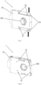
- Fig. 1 shows an external position feedback module 1 according to the present disclosure, which includes a housing 10 for holding components of the module.
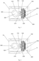
- the internal structure of the external position feedback module 1 is shown in Fig. 2 , and includes a first microswitch 100, a second microswitch 200, a rotation component 300, and connection terminals 400 formed on the first microswitch 100 and the second microswitch 200.
- the connection terminals 400 are protected by a terminal cover 11 detachably installed to the housing 10. When it is needed to wire the external position feedback module 1, the terminal cover 11 can be removed to expose the connection terminals 400.
- the rotation component 300 is rotatably installed to the housing 10, and includes a main body 310 and a mating protrusion 320 extending from the main body, and the mating protrusion 320 is, for example, in the shape of a spline.
- the mating protrusion 320 of the rotation component extends from the main body 310 and protrudes out of an outer surface of the housing 10.
- the side from which the mating protrusion 320 protrudes will be referred to as a first side of the external position feedback module 1 and the housing 10, and the side of the housing 10 opposite to the first side will be referred to as the second side.
- the mating protrusion 320 of the rotation component is configured to be coupled to the main shaft of the electrical switch.
- a housing of the electrical switch 2 is provided with a part for docking with the external position feedback module 1, and a mating recess 21 with a complementary shape to the mating protrusion 320 is provided in this part, the mating recess 21 is connected with the main shaft of the electrical switch 2 so that the mating protrusion 320 can be inserted into the mating recess 21, and the rotation of the main shaft drives the rotation of the mating recess 21 and thus drives the rotation component 300 of the external position feedback module 1 to rotate.
- the main shaft of the electrical switch has three different rotation positions according to the on and off of the circuit, and accordingly, the rotation component 300 of the external position feedback module 1 can be actuated to three positions, namely a first position, a second position and a third position.
- Three positions of the rotation component 300 and three trigger modes of the first microswitch 100 and the second microswitch 200 will be described with reference to Figs. 4 to 6 .
- the external position feedback module 1 includes a first slider 110, a second slider 210, a first spring 120 installed to the first slider 110 and a second spring 220 installed to the second slider 210.
- One end of the first slider 110 abuts the first microswitch 100, and the other end of the first slider 110 is adjacent to the outer contour of the main body 310 of the rotation component 300.
- One end of the second slider 210 abuts the second microswitch 200, and the other end of the second slider 210 is adjacent to the outer contour of the main body 310 of the rotation component 300.
- the outer contour of the main body 310 of the rotation component is roughly elliptical, and when the rotation component rotates to different positions, the first slider 110 and the second slider 210 can be pushed respectively, or both of the first slider 110 and the second slider 210 can be pushed to slide to the right at the same time, so as to trigger the first microswitch 100 and/or the second microswitch 200.
- the first spring 120 pushes the first slider 110 to slide to the left and return to the original position, releasing the first microswitch 100;
- the second spring 220 pushes the second slider 210 to slide to the left and return to the original position, releasing the second microswitch 200.
- the electrical switch is in the I position, the rotation component 300 rotates to the first position along with the main shaft of the electrical switch, the outer contour of the main body 310 of the rotation component 300 pushes the first slider 110 to slide to the right, the first spring 120 is compressed, and the first microswitch 100 is triggered; the second slider 210 is not pushed, the second spring 220 is not compressed, and the second microswitch 200 is in a released state.
- the electrical switch is in position II, the rotation component 300 rotates to the second position along with the main shaft of the electrical switch, the outer contour of the main body 310 of the rotation component 300 pushes the second slider 210 to slide to the right, the second spring 220 is compressed, and the second microswitch 200 is triggered; the first slider 110 is not pushed, the first spring 120 is not compressed, and the first microswitch 100 is in a released state.
- the electrical switch is in the 0 position, and the rotation component 300 rotates to the third position along with the main shaft of the electrical switch.
- Both the first slider 110 and the second slider 210 are pushed to the right by the outer contour of the main body 310 of the rotation component 300, and both the first spring 120 and the second spring 220 are compressed, and both the first microswitch 100 and the second microswitch 200 are triggered.
- the state of the internal circuit of the electrical switch corresponds to the trigger states of the microswitches of the external position feedback module, and the current state of the circuit of the electrical switch can be simply fed back by connecting an external device to the connection terminals 400 of the external position feedback module 1.
- the external position feedback module 1 according to the present disclosure can also be used in superposition, so as to meet the need of user who want to add more connection terminals on the electrical switch to realize more monitoring.
- Figs. 7 and 8 respectively show a first side and a second side of the external position feedback module 1 according to the present disclosure.
- the side of the rotation component 300 opposite to the mating protrusion 320 is provided with a mating recess 330 with a complementary shape to the mating protrusion, and another external position feedback module 1' can be inserted into the mating recess 330, so that the rotation of the main shaft of the electrical switch can simultaneously drive the rotation components 300 of a plurality of external position feedback modules to rotate.
- Fig. 8 the side of the rotation component 300 opposite to the mating protrusion 320 is provided with a mating recess 330 with a complementary shape to the mating protrusion, and another external position feedback module 1' can be inserted into the mating recess 330, so that the rotation of the main shaft of
- FIG. 9 shows a schematic diagram in which two external position feedback modules 1, 1' connected in series are superimposed and installed outside the electrical switch 2. Of course, more external position feedback modules can be superimposed. As illustrated by Fig. 10 , four external position feedback modules connected in series are installed on both sides of the electrical switch 2.
- the first side of the housing 10 of the external position feedback module 1 is also provided with a snap feature 12, for example, the snap feature 12 is a protrusion with a hook-shaped end.
- a snap fitting feature 13 in the form of a notch is provided at a corresponding position on the second side of the housing 10.
- the snap feature 12 is preferably provided on a depressible part 14 made of a deformable material on both sides of the housing 10, so that the insertion and removal operation can be easily performed by pressing the depressible part 14 in the direction indicated by the arrow in Fig. 7 .
- the snap feature 12 can also be used for the engagement of the external position feedback module 1 with the electrical switch housing.
- a positioning feature 321 for positioning are also provided on the mating protrusion 320 to prevent the external position feedback modules 1 from being installed to each other in a wrong orientation.
- the positioning feature 321 is, for example, a protrusion 321 protruding radially outward from a tooth of the mating protrusion 320 in the form of spline.
- the mating recess 330 is also provided with a mating positioning feature 331 corresponding to the positioning feature 321.
Landscapes
- Switch Cases, Indication, And Locking (AREA)
- Switches With Compound Operations (AREA)
Abstract
An external position feedback module 1 for an electrical switch comprising a housing 10; a first microswitch 100 and a second microswitch 200, fixed inside the housing, and the first microswitch and the second microswitch being able to be triggered and released respectively; a rotation component 300, rotatably installed to the housing, including a main body 310 accommodated in the housing and a mating protrusion 320 extending from the main body and protruding out of an outer surface of a first side of the housing, wherein the mating protrusion 320 is configured to be coupled to a main shaft of the electrical switch so that the rotation component 300 is able to rotate together with a rotation of the main shaft, and an outer contour of the main body 310is configured to trigger the first microswitch 100 and/or the second microswitch 200; and connection terminals 400, formed on the first microswitch and the second microswitch, and configured to be connected with an external device to transmit position feedback information.
Description
- The present disclosure relates to an external position feedback module for an electrical switch and an electrical switch assembly including the external position feedback module.
- During the operation of the electrical switch, sometimes users want to know the working state of the internal circuit of the switch. However, direct wiring from the inside of the electrical switch may be complicated and expensive.
- Therefore, it is desirable to provide a module that can be simply installed from outside the electrical switch and can monitor and feed back the current state of the circuit of the switch in real time.
- The purpose of the present disclosure is to solve the above requirements, and provide a module that can feed back the working state of the internal circuit of the electrical switch from the outside, and reflect the rotation of the main shaft through the position of a rotation component connected to the main shaft of the electrical switch, so as to understand the on and off of the circuit.
- An external position feedback module for an electrical switch according to an embodiment of the present disclosure includes: a housing; a first microswitch and a second microswitch, fixed inside the housing, and the first microswitch and the second microswitch being able to be triggered and released respectively; a rotation component, rotatably installed to the housing, including a main body accommodated in the housing and a mating protrusion extending from the main body and protruding out of an outer surface of a first side of the housing, where the mating protrusion is configured to be coupled to a main shaft of the electrical switch so that the rotation component is able to rotate together with a rotation of the main shaft, and an outer contour of the main body is configured to trigger the first microswitch and/or the second microswitch; and connection terminals, formed on the first microswitch and the second microswitch, and configured to be connected with an external device to transmit position feedback information.
- According to a preferable embodiment of the present disclosure, the rotation component is able to rotate to a first position, a second position and a third position, where the first microswitch and the second microswitch have three trigger modes:
- i) when the rotation component rotates to the first position, the first microswitch is triggered and the second microswitch is released;
- ii) when the rotation component rotates to the second position, the second microswitch is triggered and the first microswitch is released;
- iii) when the rotation component rotates to the third position, both the first microswitch and the second microswitch are triggered.
- According to a preferable embodiment of the present disclosure, the external position feedback module further includes a first slider, a second slider, a first spring and a second spring, where the first slider is adjacent to the first microswitch, the second slider is adjacent to the second microswitch, the first spring is installed to the first slider, and the second spring is installed to the second slider, an outer contour of a main body of the rotation component pushes the first slider and/or the second slider to trigger the first microswitch and the second microswitch respectively, and when the rotation component stops pushing the first slider and/or the second slider, the first slider and the second slider are respectively reset by the first spring or the second spring.
- According to a preferable embodiment of the present disclosure, when the rotation component rotates to the first position, the outer contour of the main body of the rotation component pushes the first slider without pushing the second slider; when the rotation component rotates to the second position, the outer contour of the main body of the rotation component pushes the second slider without pushing the first slider; when the rotation component rotates to the third position, the outer contour of the main body of the rotation component pushes the first slider and the second slider at the same time.
- According to a preferable embodiment of the present disclosure, a mating recess with a complementary shape to the mating protrusion is formed on a side of the rotation component opposite to the mating protrusion, and the mating recess can be accessed from a second side of the housing opposite to the first side, so that a mating protrusion of another external position feedback module can be inserted into the mating recess.
- According to a preferable embodiment of the present disclosure, the mating protrusion is in a shape of a spline, and a tooth of the spline is provided with a positioning feature.
- According to a preferable embodiment of the present disclosure, the first side of the housing of the external position feedback module is provided with a snap feature, and a second side of the housing opposite to the first side is provided with a snap fitting feature matched with the snap feature.
- According to a second aspect of the present disclosure, an electrical switch assembly is provided and includes an electrical switch and the abovementioned external position feedback module.
- Especially, the electrical switch assembly includes a plurality of external position feedback modules, and the plurality of external position feedback modules are connected in series with each other by inserting the mating protrusion of the rotation component of one external position feedback module into the mating recess of another external position feedback module, so that the rotation of the main shaft of the electrical switch is able to simultaneously drive rotation components of the plurality of external position feedback modules to rotate.
- The abovementioned and other features and advantages of the exemplary embodiments of the present disclosure will become more apparent from the following detailed description taken in conjunction with the accompanying drawings, which are for illustrative purposes only and are not intended to limit the scope of the present disclosure in any way.
-
Fig. 1 shows an external position feedback module according to the present disclosure; -
Fig. 2 shows the internal structure of an external position feedback module according to the present disclosure; -
Fig. 3 shows an external position feedback module according to the present disclosure and an electrical switch to which the external position feedback module is installed; -
Fig. 4 shows an external position feedback module according to the present disclosure, in which the rotation component is in a first position; -
Fig. 5 shows an external position feedback module according to the present disclosure, in which the rotation component is in a second position; -
Fig. 6 shows an external position feedback module according to the present disclosure, in which the rotation component is in a third position; -
Fig. 7 shows a first side of a housing of an external position feedback module according to the present disclosure; -
Fig. 8 shows a second side of a housing of an external position feedback module according to the present disclosure; -
Fig. 9 shows a view in which two external position feedback modules according to the present disclosure are installed to an electrical switch; -
Fig. 10 shows external position feedback modules according to the present disclosure are installed to an electrical switch from both sides; and -
Fig. 11 shows a cooperative positioning feature of a rotation component of an external position feedback module according to the present disclosure. - In order to make the purpose, technical details and advantages of the technical solution of the present disclosure more clear, the technical solution of the embodiment of the present disclosure will be described clearly and completely with the accompanying drawings of specific embodiments of the present disclosure. Like reference numerals in the drawings represent like parts. It should be noted that the described embodiments is a part of the embodiments of the present disclosure, not all of the embodiments. Based on the described embodiments of the present disclosure, all other embodiments obtained by ordinary skilled in the field without creative labor belong to the scope of protection of the present disclosure.
- Compared with the embodiments shown in the accompanying drawings, the feasible embodiments within the protection scope of the present disclosure may have fewer components, other components not shown in the accompanying drawings, different components, components arranged differently or components connected differently, etc. Furthermore, two or more components in the drawings may be implemented in a single component, or a single component shown in the drawings may be implemented as a plurality of separate components.
- Unless otherwise defined, technical terms or scientific terms used herein shall have their ordinary meanings as understood by people with ordinary skills in the field to which the present disclosure belongs. The words "first", "second" and similar words used in the specification and claims of the patent application of the present disclosure do not indicate any order, quantity or importance, but are only used to distinguish different components. When the number of parts is not specified, the number of parts can be one or more; similarly, similar words such as "one", "the" and "said" do not necessarily mean quantity limitation. Similar words such as "including" or "containing" mean that the elements or objects appearing before the word cover the elements or objects listed after the word and their equivalents, without excluding other elements or objects. Similar words such as "install", "set", "connect" or "connecting" are not limited to physical or mechanical installation, setting and connection, but can include electrical installation, setting and connection, whether directly or indirectly. "Up", "Down", "Left" and "Right" are only used to indicate the relative orientation relationship when the equipment is used or the orientation relationship shown in the accompanying drawings. When the absolute position of the described object changes, the relative orientation relationship may also change accordingly.
-
Fig. 1 shows an externalposition feedback module 1 according to the present disclosure, which includes ahousing 10 for holding components of the module. The internal structure of the externalposition feedback module 1 is shown inFig. 2 , and includes afirst microswitch 100, asecond microswitch 200, arotation component 300, andconnection terminals 400 formed on thefirst microswitch 100 and thesecond microswitch 200. Theconnection terminals 400 are protected by aterminal cover 11 detachably installed to thehousing 10. When it is needed to wire the externalposition feedback module 1, theterminal cover 11 can be removed to expose theconnection terminals 400. Therotation component 300 is rotatably installed to thehousing 10, and includes amain body 310 and amating protrusion 320 extending from the main body, and themating protrusion 320 is, for example, in the shape of a spline. With reference toFig. 1 , it can be seen that themating protrusion 320 of the rotation component extends from themain body 310 and protrudes out of an outer surface of thehousing 10. Hereinafter, the side from which themating protrusion 320 protrudes will be referred to as a first side of the externalposition feedback module 1 and thehousing 10, and the side of thehousing 10 opposite to the first side will be referred to as the second side. - The
mating protrusion 320 of the rotation component is configured to be coupled to the main shaft of the electrical switch. Specifically, as illustrated byFig. 3 , a housing of theelectrical switch 2 is provided with a part for docking with the externalposition feedback module 1, and a mating recess 21 with a complementary shape to themating protrusion 320 is provided in this part, themating recess 21 is connected with the main shaft of theelectrical switch 2 so that themating protrusion 320 can be inserted into themating recess 21, and the rotation of the main shaft drives the rotation of themating recess 21 and thus drives therotation component 300 of the externalposition feedback module 1 to rotate. - According to the example of the present disclosure, the main shaft of the electrical switch has three different rotation positions according to the on and off of the circuit, and accordingly, the
rotation component 300 of the externalposition feedback module 1 can be actuated to three positions, namely a first position, a second position and a third position. Three positions of therotation component 300 and three trigger modes of thefirst microswitch 100 and thesecond microswitch 200 will be described with reference toFigs. 4 to 6 . - As can be seen from
Figs. 4 to 6 , the externalposition feedback module 1 includes afirst slider 110, asecond slider 210, afirst spring 120 installed to thefirst slider 110 and asecond spring 220 installed to thesecond slider 210. One end of thefirst slider 110 abuts thefirst microswitch 100, and the other end of thefirst slider 110 is adjacent to the outer contour of themain body 310 of therotation component 300. One end of thesecond slider 210 abuts thesecond microswitch 200, and the other end of thesecond slider 210 is adjacent to the outer contour of themain body 310 of therotation component 300. The outer contour of themain body 310 of the rotation component is roughly elliptical, and when the rotation component rotates to different positions, thefirst slider 110 and thesecond slider 210 can be pushed respectively, or both of thefirst slider 110 and thesecond slider 210 can be pushed to slide to the right at the same time, so as to trigger thefirst microswitch 100 and/or thesecond microswitch 200. When thefirst slider 110 is not pushed by therotation component 300, thefirst spring 120 pushes thefirst slider 110 to slide to the left and return to the original position, releasing thefirst microswitch 100; when thesecond slider 210 is not pushed by therotation component 300, thesecond spring 220 pushes thesecond slider 210 to slide to the left and return to the original position, releasing thesecond microswitch 200. - In
Fig. 4 , the electrical switch is in the I position, therotation component 300 rotates to the first position along with the main shaft of the electrical switch, the outer contour of themain body 310 of therotation component 300 pushes thefirst slider 110 to slide to the right, thefirst spring 120 is compressed, and thefirst microswitch 100 is triggered; thesecond slider 210 is not pushed, thesecond spring 220 is not compressed, and thesecond microswitch 200 is in a released state. - In
Fig. 5 , the electrical switch is in position II, therotation component 300 rotates to the second position along with the main shaft of the electrical switch, the outer contour of themain body 310 of therotation component 300 pushes thesecond slider 210 to slide to the right, thesecond spring 220 is compressed, and thesecond microswitch 200 is triggered; thefirst slider 110 is not pushed, thefirst spring 120 is not compressed, and thefirst microswitch 100 is in a released state. - In
Fig. 6 , the electrical switch is in the 0 position, and therotation component 300 rotates to the third position along with the main shaft of the electrical switch. Both thefirst slider 110 and thesecond slider 210 are pushed to the right by the outer contour of themain body 310 of therotation component 300, and both thefirst spring 120 and thesecond spring 220 are compressed, and both thefirst microswitch 100 and thesecond microswitch 200 are triggered. - Thus, the state of the internal circuit of the electrical switch corresponds to the trigger states of the microswitches of the external position feedback module, and the current state of the circuit of the electrical switch can be simply fed back by connecting an external device to the
connection terminals 400 of the externalposition feedback module 1. - Preferably, the external
position feedback module 1 according to the present disclosure can also be used in superposition, so as to meet the need of user who want to add more connection terminals on the electrical switch to realize more monitoring.Figs. 7 and 8 respectively show a first side and a second side of the externalposition feedback module 1 according to the present disclosure. As can be seen fromFig. 8 , the side of therotation component 300 opposite to themating protrusion 320 is provided with amating recess 330 with a complementary shape to the mating protrusion, and another external position feedback module 1' can be inserted into themating recess 330, so that the rotation of the main shaft of the electrical switch can simultaneously drive therotation components 300 of a plurality of external position feedback modules to rotate.Fig. 9 shows a schematic diagram in which two externalposition feedback modules 1, 1' connected in series are superimposed and installed outside theelectrical switch 2. Of course, more external position feedback modules can be superimposed. As illustrated byFig. 10 , four external position feedback modules connected in series are installed on both sides of theelectrical switch 2. - In order to facilitate the installation of the external position feedback module, as illustrated by
Fig. 7 , the first side of thehousing 10 of the externalposition feedback module 1 is also provided with asnap feature 12, for example, thesnap feature 12 is a protrusion with a hook-shaped end. Correspondingly, as illustrated byFig. 8 , a snapfitting feature 13 in the form of a notch is provided at a corresponding position on the second side of thehousing 10. Thesnap feature 12 is preferably provided on adepressible part 14 made of a deformable material on both sides of thehousing 10, so that the insertion and removal operation can be easily performed by pressing thedepressible part 14 in the direction indicated by the arrow inFig. 7 . In addition, thesnap feature 12 can also be used for the engagement of the externalposition feedback module 1 with the electrical switch housing. - Particularly preferably, because the external
position feedback modules 1 can be installed to the housing of the electrical switch from both sides, apositioning feature 321 for positioning are also provided on themating protrusion 320 to prevent the externalposition feedback modules 1 from being installed to each other in a wrong orientation. As illustrated byFig. 7 , thepositioning feature 321 is, for example, aprotrusion 321 protruding radially outward from a tooth of themating protrusion 320 in the form of spline. Correspondingly, as illustrated byFig. 11 , themating recess 330 is also provided with amating positioning feature 331 corresponding to thepositioning feature 321. - Although the present disclosure has been described in the specification and illustrated in the drawings on the basis of referring to various embodiments, those skilled in the art can understand that the above embodiments are only preferred embodiments, and some technical features in the embodiments may not be necessary for solving specific technical problems, so these technical features can be omitted or omitted without affecting the solution of technical problems or the formation of technical solutions. Moreover, the features, elements and/or functions of one embodiment can be combined, combined or coordinated with those of one or more other embodiments as appropriate, unless the combination, combination or coordination is obviously impracticable.
Claims (9)
- An external position feedback module for an electrical switch, which is characterized in that, the external position feedback module comprises:a housing;a first microswitch and a second microswitch, fixed inside the housing, and the first microswitch and the second microswitch being able to be triggered and released respectively;a rotation component, rotatably installed to the housing, comprising a main body accommodated in the housing and a mating protrusion extending from the main body and protruding out of an outer surface of a first side of the housing, wherein the mating protrusion is configured to be coupled to a main shaft of the electrical switch so that the rotation component is able to rotate together with a rotation of the main shaft, and an outer contour of the main body is configured to trigger the first microswitch and/or the second microswitch; andconnection terminals, formed on the first microswitch and the second microswitch, and configured to be connected with an external device to transmit position feedback information.
- The external position feedback module according to claim 1, which is characterized in that the rotation component is able to rotate to a first position, a second position and a third position, wherein the first microswitch and the second microswitch have three trigger modes:i) when the rotation component rotates to the first position, the first microswitch is triggered and the second microswitch is released;ii) when the rotation component rotates to the second position, the second microswitch is triggered and the first microswitch is released;iii) when the rotation component rotates to the third position, both the first microswitch and the second microswitch are triggered.
- The external position feedback module according to claim 2, which is characterized in that the external position feedback module further comprises a first slider, a second slider, a first spring and a second spring, wherein the first slider is adjacent to the first microswitch, the second slider is adjacent to the second microswitch, the first spring is installed to the first slider, and the second spring is installed to the second slider, an outer contour of a main body of the rotation component pushes the first slider and/or the second slider to trigger the first microswitch and the second microswitch respectively, and when the rotation component stops pushing the first slider and/or the second slider, the first slider and the second slider are respectively reset by the first spring or the second spring.
- The external position feedback module according to claim 3, which is characterized in that, when the rotation component rotates to the first position, the outer contour of the main body of the rotation component pushes the first slider without pushing the second slider;when the rotation component rotates to the second position, the outer contour of the main body of the rotation component pushes the second slider without pushing the first slider;when the rotation component rotates to the third position, the outer contour of the main body of the rotation component pushes the first slider and the second slider at the same time.
- The external position feedback module according to any one of claims 1-4, which is characterized in that a mating recess with a complementary shape to the mating protrusion is formed on a side of the rotation component opposite to the mating protrusion, and the mating recess can be accessed from a second side of the housing opposite to the first side, so that a mating protrusion of another external position feedback module can be inserted into the mating recess.
- The external position feedback module according to claim 5, which is characterized in that the mating protrusion is in a shape of a spline, and a tooth of the spline is provided with a positioning feature.
- The external position feedback module according to claim 1, which is characterized in that the first side of the housing of the external position feedback module is provided with a snap feature, and a second side of the housing opposite to the first side is provided with a snap fitting feature matched with the snap feature.
- An electrical switch assembly, which is characterized in that, comprising an electrical switch and the external position feedback module according to any one of claims 1-7.
- The electrical switch assembly according to claim 8, which is characterized in that the electrical switch assembly comprises a plurality of external position feedback modules, and the plurality of external position feedback modules are connected in series with each other by inserting the mating protrusion of the rotation component of one external position feedback module into the mating recess of another external position feedback module, so that the rotation of the main shaft of the electrical switch is able to simultaneously drive rotation components of the plurality of external position feedback modules to rotate.
Applications Claiming Priority (1)
| Application Number | Priority Date | Filing Date | Title |
|---|---|---|---|
| CN202322019356.7U CN220367827U (en) | 2023-07-28 | 2023-07-28 | External position feedback module for an electrical switch and electrical switch assembly |
Publications (1)
| Publication Number | Publication Date |
|---|---|
| EP4498395A1 true EP4498395A1 (en) | 2025-01-29 |
Family
ID=89514552
Family Applications (1)
| Application Number | Title | Priority Date | Filing Date |
|---|---|---|---|
| EP24306258.5A Pending EP4498395A1 (en) | 2023-07-28 | 2024-07-25 | External position feedback module for electrical switch and electrical switch assembly |
Country Status (2)
| Country | Link |
|---|---|
| EP (1) | EP4498395A1 (en) |
| CN (1) | CN220367827U (en) |
Citations (5)
| Publication number | Priority date | Publication date | Assignee | Title |
|---|---|---|---|---|
| DE9302254U1 (en) * | 1993-02-17 | 1993-08-19 | Klöckner-Moeller GmbH, 53115 Bonn | Signaling device for signaling a short circuit and / or overcurrent release |
| CN100573772C (en) * | 2004-01-19 | 2009-12-23 | Abb有限公司 | Switching device module |
| WO2019185996A1 (en) * | 2018-03-29 | 2019-10-03 | Hager-Electro Sas | Auxiliary device for circuit-breaking switch with moulded case, and circuit-breaking switch with moulded case comprising said auxiliary device |
| CN212625429U (en) * | 2020-07-15 | 2021-02-26 | 施耐德电器工业公司 | Circuit breaker state indicating device and circuit breaker assembly |
| EP3889982A1 (en) * | 2020-04-01 | 2021-10-06 | Beijing Green Century Technology Co., Ltd | Automatic disconnection mechanism for switches |
-
2023
- 2023-07-28 CN CN202322019356.7U patent/CN220367827U/en active Active
-
2024
- 2024-07-25 EP EP24306258.5A patent/EP4498395A1/en active Pending
Patent Citations (5)
| Publication number | Priority date | Publication date | Assignee | Title |
|---|---|---|---|---|
| DE9302254U1 (en) * | 1993-02-17 | 1993-08-19 | Klöckner-Moeller GmbH, 53115 Bonn | Signaling device for signaling a short circuit and / or overcurrent release |
| CN100573772C (en) * | 2004-01-19 | 2009-12-23 | Abb有限公司 | Switching device module |
| WO2019185996A1 (en) * | 2018-03-29 | 2019-10-03 | Hager-Electro Sas | Auxiliary device for circuit-breaking switch with moulded case, and circuit-breaking switch with moulded case comprising said auxiliary device |
| EP3889982A1 (en) * | 2020-04-01 | 2021-10-06 | Beijing Green Century Technology Co., Ltd | Automatic disconnection mechanism for switches |
| CN212625429U (en) * | 2020-07-15 | 2021-02-26 | 施耐德电器工业公司 | Circuit breaker state indicating device and circuit breaker assembly |
Also Published As
| Publication number | Publication date |
|---|---|
| CN220367827U (en) | 2024-01-19 |
Similar Documents
| Publication | Publication Date | Title |
|---|---|---|
| US8096818B2 (en) | Modular wiring system with locking elements | |
| US7287994B1 (en) | Modular plug device | |
| US9004951B2 (en) | Multi-functional transfer connector for connecting with different receptacles | |
| EP2858183A2 (en) | Connector joining structure | |
| CN111786186B (en) | Adapters and Rail Sockets | |
| CN110233549B (en) | Electronic control module integrated motor assembly | |
| WO2015089893A1 (en) | Adapter module of usb electric connector | |
| US20240341436A1 (en) | Rotating curling iron | |
| US6638090B2 (en) | Waterproof connector used for a flexible flat cable | |
| CN210957173U (en) | Ethernet fast plugging electric connector | |
| JP2004356057A (en) | Relay connection circuit and relay connector | |
| US20090181578A1 (en) | Connector assembly | |
| TWI602210B (en) | Time switch | |
| JP2001102136A (en) | Electronic device connection device, USB connection device, and electronic device with coupling mechanism | |
| CN220367827U (en) | External position feedback module for an electrical switch and electrical switch assembly | |
| CN220400984U (en) | Waterproof power connector of many wires | |
| CN218939562U (en) | breaker | |
| JP2011181199A (en) | Mating structure and electrical connector using the same | |
| JP2622221B2 (en) | Connector with terminal lock | |
| JP2011192604A (en) | Cable plug device | |
| US20140141652A1 (en) | Hand-held electronic device, battery with connector, battery lid, connector and connector disconnection preventing method | |
| JP3515084B2 (en) | Hinge connector and circuit board connected to the connector | |
| JP2001196129A (en) | Waterproof connector | |
| CN110829130A (en) | Power transfer kit | |
| JP3750876B2 (en) | Changeover switch unit |
Legal Events
| Date | Code | Title | Description |
|---|---|---|---|
| PUAI | Public reference made under article 153(3) epc to a published international application that has entered the european phase |
Free format text: ORIGINAL CODE: 0009012 |
|
| STAA | Information on the status of an ep patent application or granted ep patent |
Free format text: STATUS: THE APPLICATION HAS BEEN PUBLISHED |
|
| AK | Designated contracting states |
Kind code of ref document: A1 Designated state(s): AL AT BE BG CH CY CZ DE DK EE ES FI FR GB GR HR HU IE IS IT LI LT LU LV MC ME MK MT NL NO PL PT RO RS SE SI SK SM TR |
|
| STAA | Information on the status of an ep patent application or granted ep patent |
Free format text: STATUS: REQUEST FOR EXAMINATION WAS MADE |
|
| 17P | Request for examination filed |
Effective date: 20250711 |