EP4498355A1 - Oled display system and control method thereof - Google Patents
Oled display system and control method thereof Download PDFInfo
- Publication number
- EP4498355A1 EP4498355A1 EP24172038.2A EP24172038A EP4498355A1 EP 4498355 A1 EP4498355 A1 EP 4498355A1 EP 24172038 A EP24172038 A EP 24172038A EP 4498355 A1 EP4498355 A1 EP 4498355A1
- Authority
- EP
- European Patent Office
- Prior art keywords
- organic light
- emitting layer
- control mode
- speed
- turned
- Prior art date
- Legal status (The legal status is an assumption and is not a legal conclusion. Google has not performed a legal analysis and makes no representation as to the accuracy of the status listed.)
- Pending
Links
Images


Classifications
-
- G—PHYSICS
- G09—EDUCATION; CRYPTOGRAPHY; DISPLAY; ADVERTISING; SEALS
- G09G—ARRANGEMENTS OR CIRCUITS FOR CONTROL OF INDICATING DEVICES USING STATIC MEANS TO PRESENT VARIABLE INFORMATION
- G09G3/00—Control arrangements or circuits, of interest only in connection with visual indicators other than cathode-ray tubes
- G09G3/20—Control arrangements or circuits, of interest only in connection with visual indicators other than cathode-ray tubes for presentation of an assembly of a number of characters, e.g. a page, by composing the assembly by combination of individual elements arranged in a matrix no fixed position being assigned to or needed to be assigned to the individual characters or partial characters
- G09G3/2092—Details of a display terminals using a flat panel, the details relating to the control arrangement of the display terminal and to the interfaces thereto
-
- G—PHYSICS
- G09—EDUCATION; CRYPTOGRAPHY; DISPLAY; ADVERTISING; SEALS
- G09G—ARRANGEMENTS OR CIRCUITS FOR CONTROL OF INDICATING DEVICES USING STATIC MEANS TO PRESENT VARIABLE INFORMATION
- G09G3/00—Control arrangements or circuits, of interest only in connection with visual indicators other than cathode-ray tubes
- G09G3/20—Control arrangements or circuits, of interest only in connection with visual indicators other than cathode-ray tubes for presentation of an assembly of a number of characters, e.g. a page, by composing the assembly by combination of individual elements arranged in a matrix no fixed position being assigned to or needed to be assigned to the individual characters or partial characters
- G09G3/22—Control arrangements or circuits, of interest only in connection with visual indicators other than cathode-ray tubes for presentation of an assembly of a number of characters, e.g. a page, by composing the assembly by combination of individual elements arranged in a matrix no fixed position being assigned to or needed to be assigned to the individual characters or partial characters using controlled light sources
- G09G3/30—Control arrangements or circuits, of interest only in connection with visual indicators other than cathode-ray tubes for presentation of an assembly of a number of characters, e.g. a page, by composing the assembly by combination of individual elements arranged in a matrix no fixed position being assigned to or needed to be assigned to the individual characters or partial characters using controlled light sources using electroluminescent panels
- G09G3/32—Control arrangements or circuits, of interest only in connection with visual indicators other than cathode-ray tubes for presentation of an assembly of a number of characters, e.g. a page, by composing the assembly by combination of individual elements arranged in a matrix no fixed position being assigned to or needed to be assigned to the individual characters or partial characters using controlled light sources using electroluminescent panels semiconductive, e.g. using light-emitting diodes [LED]
- G09G3/3208—Control arrangements or circuits, of interest only in connection with visual indicators other than cathode-ray tubes for presentation of an assembly of a number of characters, e.g. a page, by composing the assembly by combination of individual elements arranged in a matrix no fixed position being assigned to or needed to be assigned to the individual characters or partial characters using controlled light sources using electroluminescent panels semiconductive, e.g. using light-emitting diodes [LED] organic, e.g. using organic light-emitting diodes [OLED]
-
- H—ELECTRICITY
- H10—SEMICONDUCTOR DEVICES; ELECTRIC SOLID-STATE DEVICES NOT OTHERWISE PROVIDED FOR
- H10K—ORGANIC ELECTRIC SOLID-STATE DEVICES
- H10K50/00—Organic light-emitting devices
- H10K50/10—OLEDs or polymer light-emitting diodes [PLED]
- H10K50/11—OLEDs or polymer light-emitting diodes [PLED] characterised by the electroluminescent [EL] layers
- H10K50/125—OLEDs or polymer light-emitting diodes [PLED] characterised by the electroluminescent [EL] layers specially adapted for multicolour light emission, e.g. for emitting white light
- H10K50/13—OLEDs or polymer light-emitting diodes [PLED] characterised by the electroluminescent [EL] layers specially adapted for multicolour light emission, e.g. for emitting white light comprising stacked EL layers within one EL unit
- H10K50/131—OLEDs or polymer light-emitting diodes [PLED] characterised by the electroluminescent [EL] layers specially adapted for multicolour light emission, e.g. for emitting white light comprising stacked EL layers within one EL unit with spacer layers between the electroluminescent layers
-
- B—PERFORMING OPERATIONS; TRANSPORTING
- B60—VEHICLES IN GENERAL
- B60K—ARRANGEMENT OR MOUNTING OF PROPULSION UNITS OR OF TRANSMISSIONS IN VEHICLES; ARRANGEMENT OR MOUNTING OF PLURAL DIVERSE PRIME-MOVERS IN VEHICLES; AUXILIARY DRIVES FOR VEHICLES; INSTRUMENTATION OR DASHBOARDS FOR VEHICLES; ARRANGEMENTS IN CONNECTION WITH COOLING, AIR INTAKE, GAS EXHAUST OR FUEL SUPPLY OF PROPULSION UNITS IN VEHICLES
- B60K35/00—Instruments specially adapted for vehicles; Arrangement of instruments in or on vehicles
- B60K35/20—Output arrangements, i.e. from vehicle to user, associated with vehicle functions or specially adapted therefor
- B60K35/21—Output arrangements, i.e. from vehicle to user, associated with vehicle functions or specially adapted therefor using visual output, e.g. blinking lights or matrix displays
- B60K35/22—Display screens
-
- B—PERFORMING OPERATIONS; TRANSPORTING
- B60—VEHICLES IN GENERAL
- B60K—ARRANGEMENT OR MOUNTING OF PROPULSION UNITS OR OF TRANSMISSIONS IN VEHICLES; ARRANGEMENT OR MOUNTING OF PLURAL DIVERSE PRIME-MOVERS IN VEHICLES; AUXILIARY DRIVES FOR VEHICLES; INSTRUMENTATION OR DASHBOARDS FOR VEHICLES; ARRANGEMENTS IN CONNECTION WITH COOLING, AIR INTAKE, GAS EXHAUST OR FUEL SUPPLY OF PROPULSION UNITS IN VEHICLES
- B60K35/00—Instruments specially adapted for vehicles; Arrangement of instruments in or on vehicles
- B60K35/20—Output arrangements, i.e. from vehicle to user, associated with vehicle functions or specially adapted therefor
- B60K35/21—Output arrangements, i.e. from vehicle to user, associated with vehicle functions or specially adapted therefor using visual output, e.g. blinking lights or matrix displays
- B60K35/23—Head-up displays [HUD]
- B60K35/234—Head-up displays [HUD] controlling the brightness, colour or contrast of virtual images depending on the driving conditions or on the condition of the vehicle or the driver
-
- B—PERFORMING OPERATIONS; TRANSPORTING
- B60—VEHICLES IN GENERAL
- B60K—ARRANGEMENT OR MOUNTING OF PROPULSION UNITS OR OF TRANSMISSIONS IN VEHICLES; ARRANGEMENT OR MOUNTING OF PLURAL DIVERSE PRIME-MOVERS IN VEHICLES; AUXILIARY DRIVES FOR VEHICLES; INSTRUMENTATION OR DASHBOARDS FOR VEHICLES; ARRANGEMENTS IN CONNECTION WITH COOLING, AIR INTAKE, GAS EXHAUST OR FUEL SUPPLY OF PROPULSION UNITS IN VEHICLES
- B60K37/00—Dashboards
-
- B—PERFORMING OPERATIONS; TRANSPORTING
- B60—VEHICLES IN GENERAL
- B60R—VEHICLES, VEHICLE FITTINGS, OR VEHICLE PARTS, NOT OTHERWISE PROVIDED FOR
- B60R11/00—Arrangements for holding or mounting articles, not otherwise provided for
- B60R11/02—Arrangements for holding or mounting articles, not otherwise provided for for radio sets, television sets, telephones, or the like; Arrangement of controls thereof
- B60R11/0229—Arrangements for holding or mounting articles, not otherwise provided for for radio sets, television sets, telephones, or the like; Arrangement of controls thereof for displays, e.g. cathodic tubes
-
- G—PHYSICS
- G09—EDUCATION; CRYPTOGRAPHY; DISPLAY; ADVERTISING; SEALS
- G09F—DISPLAYING; ADVERTISING; SIGNS; LABELS OR NAME-PLATES; SEALS
- G09F9/00—Indicating arrangements for variable information in which the information is built-up on a support by selection or combination of individual elements
- G09F9/30—Indicating arrangements for variable information in which the information is built-up on a support by selection or combination of individual elements in which the desired character or characters are formed by combining individual elements
- G09F9/33—Indicating arrangements for variable information in which the information is built-up on a support by selection or combination of individual elements in which the desired character or characters are formed by combining individual elements being semiconductor devices, e.g. diodes
- G09F9/335—Indicating arrangements for variable information in which the information is built-up on a support by selection or combination of individual elements in which the desired character or characters are formed by combining individual elements being semiconductor devices, e.g. diodes being organic light emitting diodes [OLED]
-
- G—PHYSICS
- G09—EDUCATION; CRYPTOGRAPHY; DISPLAY; ADVERTISING; SEALS
- G09G—ARRANGEMENTS OR CIRCUITS FOR CONTROL OF INDICATING DEVICES USING STATIC MEANS TO PRESENT VARIABLE INFORMATION
- G09G2300/00—Aspects of the constitution of display devices
- G09G2300/02—Composition of display devices
- G09G2300/023—Display panel composed of stacked panels
-
- G—PHYSICS
- G09—EDUCATION; CRYPTOGRAPHY; DISPLAY; ADVERTISING; SEALS
- G09G—ARRANGEMENTS OR CIRCUITS FOR CONTROL OF INDICATING DEVICES USING STATIC MEANS TO PRESENT VARIABLE INFORMATION
- G09G2310/00—Command of the display device
- G09G2310/02—Addressing, scanning or driving the display screen or processing steps related thereto
- G09G2310/0243—Details of the generation of driving signals
-
- G—PHYSICS
- G09—EDUCATION; CRYPTOGRAPHY; DISPLAY; ADVERTISING; SEALS
- G09G—ARRANGEMENTS OR CIRCUITS FOR CONTROL OF INDICATING DEVICES USING STATIC MEANS TO PRESENT VARIABLE INFORMATION
- G09G2310/00—Command of the display device
- G09G2310/02—Addressing, scanning or driving the display screen or processing steps related thereto
- G09G2310/0264—Details of driving circuits
-
- G—PHYSICS
- G09—EDUCATION; CRYPTOGRAPHY; DISPLAY; ADVERTISING; SEALS
- G09G—ARRANGEMENTS OR CIRCUITS FOR CONTROL OF INDICATING DEVICES USING STATIC MEANS TO PRESENT VARIABLE INFORMATION
- G09G2320/00—Control of display operating conditions
- G09G2320/02—Improving the quality of display appearance
- G09G2320/0233—Improving the luminance or brightness uniformity across the screen
-
- G—PHYSICS
- G09—EDUCATION; CRYPTOGRAPHY; DISPLAY; ADVERTISING; SEALS
- G09G—ARRANGEMENTS OR CIRCUITS FOR CONTROL OF INDICATING DEVICES USING STATIC MEANS TO PRESENT VARIABLE INFORMATION
- G09G2320/00—Control of display operating conditions
- G09G2320/02—Improving the quality of display appearance
- G09G2320/028—Improving the quality of display appearance by changing the viewing angle properties, e.g. widening the viewing angle, adapting the viewing angle to the view direction
-
- G—PHYSICS
- G09—EDUCATION; CRYPTOGRAPHY; DISPLAY; ADVERTISING; SEALS
- G09G—ARRANGEMENTS OR CIRCUITS FOR CONTROL OF INDICATING DEVICES USING STATIC MEANS TO PRESENT VARIABLE INFORMATION
- G09G2320/00—Control of display operating conditions
- G09G2320/06—Adjustment of display parameters
- G09G2320/0626—Adjustment of display parameters for control of overall brightness
-
- G—PHYSICS
- G09—EDUCATION; CRYPTOGRAPHY; DISPLAY; ADVERTISING; SEALS
- G09G—ARRANGEMENTS OR CIRCUITS FOR CONTROL OF INDICATING DEVICES USING STATIC MEANS TO PRESENT VARIABLE INFORMATION
- G09G2320/00—Control of display operating conditions
- G09G2320/06—Adjustment of display parameters
- G09G2320/0666—Adjustment of display parameters for control of colour parameters, e.g. colour temperature
-
- G—PHYSICS
- G09—EDUCATION; CRYPTOGRAPHY; DISPLAY; ADVERTISING; SEALS
- G09G—ARRANGEMENTS OR CIRCUITS FOR CONTROL OF INDICATING DEVICES USING STATIC MEANS TO PRESENT VARIABLE INFORMATION
- G09G2320/00—Control of display operating conditions
- G09G2320/06—Adjustment of display parameters
- G09G2320/0673—Adjustment of display parameters for control of gamma adjustment, e.g. selecting another gamma curve
-
- G—PHYSICS
- G09—EDUCATION; CRYPTOGRAPHY; DISPLAY; ADVERTISING; SEALS
- G09G—ARRANGEMENTS OR CIRCUITS FOR CONTROL OF INDICATING DEVICES USING STATIC MEANS TO PRESENT VARIABLE INFORMATION
- G09G2320/00—Control of display operating conditions
- G09G2320/06—Adjustment of display parameters
- G09G2320/068—Adjustment of display parameters for control of viewing angle adjustment
-
- G—PHYSICS
- G09—EDUCATION; CRYPTOGRAPHY; DISPLAY; ADVERTISING; SEALS
- G09G—ARRANGEMENTS OR CIRCUITS FOR CONTROL OF INDICATING DEVICES USING STATIC MEANS TO PRESENT VARIABLE INFORMATION
- G09G2358/00—Arrangements for display data security
-
- G—PHYSICS
- G09—EDUCATION; CRYPTOGRAPHY; DISPLAY; ADVERTISING; SEALS
- G09G—ARRANGEMENTS OR CIRCUITS FOR CONTROL OF INDICATING DEVICES USING STATIC MEANS TO PRESENT VARIABLE INFORMATION
- G09G2380/00—Specific applications
- G09G2380/10—Automotive applications
-
- G—PHYSICS
- G09—EDUCATION; CRYPTOGRAPHY; DISPLAY; ADVERTISING; SEALS
- G09G—ARRANGEMENTS OR CIRCUITS FOR CONTROL OF INDICATING DEVICES USING STATIC MEANS TO PRESENT VARIABLE INFORMATION
- G09G3/00—Control arrangements or circuits, of interest only in connection with visual indicators other than cathode-ray tubes
- G09G3/20—Control arrangements or circuits, of interest only in connection with visual indicators other than cathode-ray tubes for presentation of an assembly of a number of characters, e.g. a page, by composing the assembly by combination of individual elements arranged in a matrix no fixed position being assigned to or needed to be assigned to the individual characters or partial characters
- G09G3/22—Control arrangements or circuits, of interest only in connection with visual indicators other than cathode-ray tubes for presentation of an assembly of a number of characters, e.g. a page, by composing the assembly by combination of individual elements arranged in a matrix no fixed position being assigned to or needed to be assigned to the individual characters or partial characters using controlled light sources
- G09G3/30—Control arrangements or circuits, of interest only in connection with visual indicators other than cathode-ray tubes for presentation of an assembly of a number of characters, e.g. a page, by composing the assembly by combination of individual elements arranged in a matrix no fixed position being assigned to or needed to be assigned to the individual characters or partial characters using controlled light sources using electroluminescent panels
- G09G3/32—Control arrangements or circuits, of interest only in connection with visual indicators other than cathode-ray tubes for presentation of an assembly of a number of characters, e.g. a page, by composing the assembly by combination of individual elements arranged in a matrix no fixed position being assigned to or needed to be assigned to the individual characters or partial characters using controlled light sources using electroluminescent panels semiconductive, e.g. using light-emitting diodes [LED]
- G09G3/3208—Control arrangements or circuits, of interest only in connection with visual indicators other than cathode-ray tubes for presentation of an assembly of a number of characters, e.g. a page, by composing the assembly by combination of individual elements arranged in a matrix no fixed position being assigned to or needed to be assigned to the individual characters or partial characters using controlled light sources using electroluminescent panels semiconductive, e.g. using light-emitting diodes [LED] organic, e.g. using organic light-emitting diodes [OLED]
- G09G3/3225—Control arrangements or circuits, of interest only in connection with visual indicators other than cathode-ray tubes for presentation of an assembly of a number of characters, e.g. a page, by composing the assembly by combination of individual elements arranged in a matrix no fixed position being assigned to or needed to be assigned to the individual characters or partial characters using controlled light sources using electroluminescent panels semiconductive, e.g. using light-emitting diodes [LED] organic, e.g. using organic light-emitting diodes [OLED] using an active matrix
-
- G—PHYSICS
- G09—EDUCATION; CRYPTOGRAPHY; DISPLAY; ADVERTISING; SEALS
- G09G—ARRANGEMENTS OR CIRCUITS FOR CONTROL OF INDICATING DEVICES USING STATIC MEANS TO PRESENT VARIABLE INFORMATION
- G09G5/00—Control arrangements or circuits for visual indicators common to cathode-ray tube indicators and other visual indicators
- G09G5/14—Display of multiple viewports
-
- H—ELECTRICITY
- H10—SEMICONDUCTOR DEVICES; ELECTRIC SOLID-STATE DEVICES NOT OTHERWISE PROVIDED FOR
- H10K—ORGANIC ELECTRIC SOLID-STATE DEVICES
- H10K59/00—Integrated devices, or assemblies of multiple devices, comprising at least one organic light-emitting element covered by group H10K50/00
- H10K59/30—Devices specially adapted for multicolour light emission
Definitions
- the following disclosure relates to an organic light emitting element (OLED) display system and a control method thereof.
- OLED organic light emitting element
- a display system of a vehicle may be mainly installed on the instrument panel, central console, entertainment system, or the like of the vehicle, and visually deliver information to a driver and a passenger in the vehicle.
- a driving information display system may provide driving-related information such as the speed, a revolution per minute (RPM), a fuel level, a mileage, or the like of the vehicle.
- This display may be mainly mounted on the instrument panel, may be configured as a digital display panel, or may be provided as a combined analog and digital display. In recent years, an electronic instrument panel has been used more, and a virtual or customized display shape may be selected in some cases.
- the display system on the central console may be mainly connected to an information entertainment system of the vehicle.
- the display may provide a navigation system, a multimedia playback, a communication function, or the like.
- a lot of vehicles may use a touch screen interface to allow a user to easily access and control the functions.
- a voice recognition function may allow the driver to perform a task such as entering a destination or connecting a mobile phone.
- the display system may have an increasingly larger size and a higher resolution, and is continuously evolving to provide more convenient and useful information to the driver and the passenger.
- a co-driver display which is also a type of the display may allow the passenger in addition to the driver to check and interact with information.
- This display may be mainly mounted on the central console or in front of a co-driver seat, and may provide a variety of functions such as entertainment, navigation, communication, and the like, these functions being recently spotlighted in a market.
- OE original equipment
- a side-window reflection may also be restricted because such a reflection may disturb the vehicle driving.
- An embodiment of the present disclosure is directed to providing an organic light emitting element (OLED) display system which may not disturb a driver's view, and a control method thereof.
- OLED organic light emitting element
- an organic light emitting element (OLED) display system disposed in a moving object, the system including: an OLED display including a first organic light-emitting layer and a second organic light-emitting layer; and a control unit controlling on/off of at least one of the first organic light-emitting layer and the second organic light-emitting layer, wherein the second organic light-emitting layer has a larger beam angle than the first organic light-emitting layer, and the control unit controls the on/off of the at least one of the first organic light-emitting layer and the second organic light-emitting layer based on a speed of the moving object.
- OLED organic light emitting element
- the control unit controls the first organic light-emitting layer and the second organic light-emitting layer in a first control mode, in which both the first organic light-emitting layer and the second organic light-emitting layer are turned on, when the speed of the moving object is zero and maintained at the same speed for a predetermined time.
- the control unit maintains the first control mode when the speed of the moving object is increased in the first control mode to be a predetermined reference speed or less, and controls the first organic light-emitting layer and the second organic light-emitting layer in a second control mode, in which the first organic light-emitting layer is turned on and the second organic light-emitting layer is turned off, when the speed of the moving object is increased in the first control mode, and maintained to be greater than the reference speed for the predetermined time.
- the control unit increases an amount of a current applied to the first organic light-emitting layer when switching the first control mode to the second control mode.
- the control unit applies pre-stored gamma and color coordinate values when switching the first control mode to the second control mode.
- a control method of an organic light emitting element (OLED) display system disposed in a moving object including an OLED display and a control unit the method including: (a) receiving, by the control unit, a speed of the moving object; and (b) controlling, by the control unit, on/off of at least one of a first organic light-emitting layer and a second organic light-emitting layer based on the speed of the moving object.
- OLED organic light emitting element
- the first organic light-emitting layer and the second organic light-emitting layer are controlled in a first control mode, in which both the first organic light-emitting layer and the second organic light-emitting layer are turned on, when the speed of the moving object is zero and maintained at the same speed for a predetermined time.
- the first control mode is maintained when the speed of the moving object is increased in the first control mode to be a predetermined reference speed or less, and the first organic light-emitting layer and the second organic light-emitting layer are controlled in a second control mode, in which the first organic light-emitting layer is turned on and the second organic light-emitting layer is turned off, when the speed of the moving object is increased in the first control mode, and maintained to be greater than the reference speed for the predetermined time.
- an amount of a current applied to the first organic light-emitting layer is increased when the first control mode is switched to the second control mode.
- pre-stored gamma and color coordinate values are applied when the first control mode is switched to the second control mode.
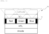
- FIG. 1 is a schematic view showing a structure of a conventional organic light emitting element (OLED) panel.
- OLED organic light emitting element
- the structure of the conventional OLED panel may include a single organic light-emitting layer 11.
- the conventional OLED panel including the single organic light-emitting layer may be required to always be controlled in a shared mode.
- a driver and a passenger in a co-driver seat may have no choice but to share one image together.
- FIG. 2 is a schematic view showing an OLED display system according to an embodiment of the present disclosure
- FIGS. 3A and 3B are schematic views each showing an OLED structure according to an embodiment of the present disclosure.
- an OLED display system 1000 disposed in a moving object may include an OLED display 100 and a control unit 200.
- the control unit 200 (or controller) may be implemented with a circuit, or alternatively, by a processor together with a non-transitory computer-readable storage medium storing commands, when executed by the processor, causing the processor to perform various operations described with reference to the control unit 200.
- the OLED display 100 may include an anode A and a cathode C, and include a first organic light-emitting layer 110 and a second organic light-emitting layer 120, provided between the anode A and the cathode C.
- the organic light-emitting layer may refer to a layer including a luminescent material emitting light in response to a current being applied thereto.
- the second organic light-emitting layer 120 may be stacked on the first organic light-emitting layer 110, and may be connected in parallel with each other.
- the control unit 200 may determine a control mode based on a received speed of the moving object, and control on/off of each of the first organic light-emitting layer 110 and the second organic light-emitting layer 120 based on the determined control mode.
- control unit 200 may perform the control in a first control mode in which both the first organic light-emitting layer 110 and the second organic light-emitting layer 120 are turned on.
- the driver and the passenger may share an image together in the first control mode because both the first organic light-emitting layer 110 and the second organic light-emitting layer 120 are turned on.
- control unit 200 may perform the control in a second control mode in which the first organic light-emitting layer 110 is turned on and the second organic light-emitting layer is turned off.
- the first organic light-emitting layer 110 may be turned on. Therefore, light emitted from the first organic light-emitting layer 110 may provide the image with a viewing angle limited by the second organic light-emitting layer 120.
- the OLED display 100 may include a first substrate (not shown) which is a substrate on which a plurality of pixels are arranged.
- the plurality of pixels may be gathered to produce white light, and for example, red, green, and blue pixels may be gathered to form a group.
- the OLED display 100 may include a second substrate (not shown) disposed on its surface facing the first substrate, and the second substrate (not shown) may include a plurality of color layers corresponding to the plurality of pixels described above, and may include a black matrix for distinguishing the respective pixels from each other. It is possible to prevent interference between colors and distinguish the respective colors from each other by using the black matrix of the second substrate.
- the image with the viewing angle limited by the black matrix of the second organic light-emitting layer 120 may be provided when the control unit 200 turns on only the first organic light-emitting layer 110 in the second control mode.
- FIG. 3A shows the first control mode
- FIG. 3B shows the second control mode
- control unit 200 may control the first organic light-emitting layer 110 and the second organic light-emitting layer 120 in the first control mode or the second control mode based on the speed of the moving object.
- control unit 200 may perform the control in the first control mode when the received speed of the moving object is zero and maintained at the same speed for a predetermined time.
- control unit 200 may control the control mode to be maintained at the first control mode when the speed of the moving object is increased in the first control mode to be a predetermined reference speed or less.
- control unit 200 may control the control mode to be switched to the second control mode when the speed of the moving object is increased in the first control mode, and maintained to be greater than the reference speed for the predetermined time.
- the system 1000 may have lower luminance and changed color coordinates when the mode is changed by the control unit 200, especially when the first control mode is changed to the second mode. Accordingly, the control unit 200 may increase the current applied to the first organic light-emitting layer 110 to produce brighter luminance. In addition, the control unit 200 may compensate for a change in the color coordinates by applying pre-stored gamma and color coordinate values.
- the first organic light-emitting layer 110 and the second organic light-emitting layer 120 may be operated in the first control mode when the moving object stops or has a speed not changed for the predetermined time. Therefore, the driver and the passenger may share the image together, thus ensuring driving safety.
- first organic light-emitting layer 110 and the second organic light-emitting layer 120 may be operated in the second control mode when the moving object has a speed increased to the predetermined reference speed or more, thereby preventing any disturbance to the driver while driving.
- FIG. 4 is a flowchart showing a control method of an OLED display system according to an embodiment of the present disclosure.
- the control unit 200 may receive a speed of the moving object in an operation S100, and determine a control mode based on the received speed of the moving object, and control on/off of each of a first organic light-emitting layer 110 and a second organic light-emitting layer 120 based on the determined control mode in an operation S200.
- control unit 200 may perform the control in a first control mode in which both the first organic light-emitting layer 110 and the second organic light-emitting layer 120 are turned on.
- a driver and a passenger may share an image together in the first control mode because both the first organic light-emitting layer 110 and the second organic light-emitting layer 120 are turned on.
- control unit 200 may perform the control in a second control mode in which the first organic light-emitting layer 110 is in turned on and the second organic light-emitting layer is turned off.
- the first organic light-emitting layer 110 may be turned on. Therefore, light emitted from the first organic light-emitting layer 110 may provide the image with a viewing angle limited by the second organic light-emitting layer 120.
- control unit 200 may perform the control in the first control mode when the received speed of the moving object is zero and is maintained at the same speed for a predetermined time.
- control unit 200 may control the control mode to be maintained at the first control mode when the speed of the moving object is increased in the first control mode, and belongs to a predetermined reference speed or less.
- control unit 200 may control the control mode to be switched to the second control mode when the speed of the moving object is increased in the first control mode, and maintained to be greater than the reference speed for the predetermined time.
- the system 1000 may have lower luminance and changed color coordinates when the mode is changed by the control unit 200, especially when the first control mode is changed to the second mode. Accordingly, the control unit 200 may increase a current applied to the first organic light-emitting layer 110 to produce brighter luminance. In addition, the control unit 200 may compensate for a change in the color coordinates by applying pre-stored gamma and color coordinate values.
- the OLED display system and the control method thereof may change the mode not to disturb the driver's view, thereby promoting the safety of the driver, the passenger, or a pedestrian.
- the present disclosure may satisfy various user conditions by allowing the driver to quantitatively control the display exposure amount.
- the present disclosure may use such a physically simple structure, thereby securing higher reliability.
Landscapes
- Engineering & Computer Science (AREA)
- Physics & Mathematics (AREA)
- General Physics & Mathematics (AREA)
- Theoretical Computer Science (AREA)
- Computer Hardware Design (AREA)
- Mechanical Engineering (AREA)
- Chemical & Material Sciences (AREA)
- Combustion & Propulsion (AREA)
- Transportation (AREA)
- Optics & Photonics (AREA)
- Microelectronics & Electronic Packaging (AREA)
- Electroluminescent Light Sources (AREA)
- Control Of Indicators Other Than Cathode Ray Tubes (AREA)
Abstract
Provided are an organic light emitting element (OLED) display system and a control method thereof. In more detail, the system disposed in a moving object includes: an OLED display including a first organic light-emitting layer and a second organic light-emitting layer; and a control unit controlling on/off of at least one of the first organic light-emitting layer and the second organic light-emitting layer, wherein the second organic light-emitting layer has a larger beam angle than the first organic light-emitting layer, and the control unit controls the on/off of the at least one of the first organic light-emitting layer and the second organic light-emitting layer based on a speed of the moving object.
Description
- The following disclosure relates to an organic light emitting element (OLED) display system and a control method thereof.
- A display system of a vehicle may be mainly installed on the instrument panel, central console, entertainment system, or the like of the vehicle, and visually deliver information to a driver and a passenger in the vehicle. For example, a driving information display system may provide driving-related information such as the speed, a revolution per minute (RPM), a fuel level, a mileage, or the like of the vehicle. This display may be mainly mounted on the instrument panel, may be configured as a digital display panel, or may be provided as a combined analog and digital display. In recent years, an electronic instrument panel has been used more, and a virtual or customized display shape may be selected in some cases. In addition, the display system on the central console may be mainly connected to an information entertainment system of the vehicle. The display may provide a navigation system, a multimedia playback, a communication function, or the like. A lot of vehicles may use a touch screen interface to allow a user to easily access and control the functions. In addition, in some vehicles, a voice recognition function may allow the driver to perform a task such as entering a destination or connecting a mobile phone. In addition, as an era of an electric vehicle and autonomous driving begins, the display system may have an increasingly larger size and a higher resolution, and is continuously evolving to provide more convenient and useful information to the driver and the passenger.
- In addition to the functions described above, a co-driver display which is also a type of the display may allow the passenger in addition to the driver to check and interact with information. This display may be mainly mounted on the central console or in front of a co-driver seat, and may provide a variety of functions such as entertainment, navigation, communication, and the like, these functions being recently spotlighted in a market.
- Meanwhile, as the display becomes larger and more diverse, the display within a driver's view may also become wider and more numerous. In addition, image noise may occur due to a co-driver seat display image, which may disturb the driver's driving while driving. Accordingly, it may be important to reduce a frequency of the image noise occurring in the driver's view during the driving. Recently, a major original equipment (OE) may have an increasing requirement for a display having viewing angle control technology that may limit viewing of a multimedia image to a driver direction of a front passenger display. In addition, in addition to the driver seat direction, a side-window reflection may also be restricted because such a reflection may disturb the vehicle driving.
-
- An embodiment of the present disclosure is directed to providing an organic light emitting element (OLED) display system which may not disturb a driver's view, and a control method thereof.
- In one general aspect, provided is an organic light emitting element (OLED) display system disposed in a moving object, the system including: an OLED display including a first organic light-emitting layer and a second organic light-emitting layer; and a control unit controlling on/off of at least one of the first organic light-emitting layer and the second organic light-emitting layer, wherein the second organic light-emitting layer has a larger beam angle than the first organic light-emitting layer, and the control unit controls the on/off of the at least one of the first organic light-emitting layer and the second organic light-emitting layer based on a speed of the moving object.
- The control unit controls the first organic light-emitting layer and the second organic light-emitting layer in a first control mode, in which both the first organic light-emitting layer and the second organic light-emitting layer are turned on, when the speed of the moving object is zero and maintained at the same speed for a predetermined time.
- The control unit maintains the first control mode when the speed of the moving object is increased in the first control mode to be a predetermined reference speed or less, and controls the first organic light-emitting layer and the second organic light-emitting layer in a second control mode, in which the first organic light-emitting layer is turned on and the second organic light-emitting layer is turned off, when the speed of the moving object is increased in the first control mode, and maintained to be greater than the reference speed for the predetermined time.
- The control unit increases an amount of a current applied to the first organic light-emitting layer when switching the first control mode to the second control mode.
- The control unit applies pre-stored gamma and color coordinate values when switching the first control mode to the second control mode.
- In another general aspect, provided is a control method of an organic light emitting element (OLED) display system disposed in a moving object including an OLED display and a control unit, the method including: (a) receiving, by the control unit, a speed of the moving object; and (b) controlling, by the control unit, on/off of at least one of a first organic light-emitting layer and a second organic light-emitting layer based on the speed of the moving object.
- In the operation (b), the first organic light-emitting layer and the second organic light-emitting layer are controlled in a first control mode, in which both the first organic light-emitting layer and the second organic light-emitting layer are turned on, when the speed of the moving object is zero and maintained at the same speed for a predetermined time.
- In the operation (b), the first control mode is maintained when the speed of the moving object is increased in the first control mode to be a predetermined reference speed or less, and the first organic light-emitting layer and the second organic light-emitting layer are controlled in a second control mode, in which the first organic light-emitting layer is turned on and the second organic light-emitting layer is turned off, when the speed of the moving object is increased in the first control mode, and maintained to be greater than the reference speed for the predetermined time.
- In the operation (b), an amount of a current applied to the first organic light-emitting layer is increased when the first control mode is switched to the second control mode.
- In the operation (b), pre-stored gamma and color coordinate values are applied when the first control mode is switched to the second control mode.
-
-
FIG. 1 is a schematic view showing a structure of a conventional organic light emitting element (OLED) panel. -
FIG. 2 is a schematic view showing an OLED display system according to an embodiment of the present disclosure. -
FIGS. 3A and3B are schematic views each showing an OLED structure according to an embodiment of the present disclosure. -
FIG. 4 is a flowchart showing a control method of an OLED display system according to an embodiment of the present disclosure. - In order to describe the present disclosure, operational advantages of the present disclosure, and objects accomplished by embodiments of the present disclosure, the embodiments of the present disclosure are hereinafter exemplified and described with reference to the accompanying drawings.
- First, terms used in this application are used only to describe specific embodiments rather than limiting the present disclosure, and a term of a singular number may include its plural number unless explicitly indicated otherwise in the context. It is to be understood that a term "include", "formed of", or the like used in this application specifies the existence of features, numerals, steps, operations, components, parts, or combinations thereof, which is mentioned in the specification, and does not preclude the existence or addition of one or more other features, numerals, steps, operations, components, parts or combinations thereof.
- When it is decided that the detailed description of the known configuration or function related to the present disclosure may obscure the gist of the present disclosure, the detailed description thereof will be omitted.
-
FIG. 1 is a schematic view showing a structure of a conventional organic light emitting element (OLED) panel. - As shown in
FIG. 1 , the structure of the conventional OLED panel may include a single organic light-emitting layer 11. - In this case, the conventional OLED panel including the single organic light-emitting layer may be required to always be controlled in a shared mode.
- That is, a driver and a passenger in a co-driver seat may have no choice but to share one image together.
-
FIG. 2 is a schematic view showing an OLED display system according to an embodiment of the present disclosure; andFIGS. 3A and3B are schematic views each showing an OLED structure according to an embodiment of the present disclosure. - As shown in
FIG. 2 , anOLED display system 1000 disposed in a moving object according to the present disclosure may include anOLED display 100 and acontrol unit 200. The control unit 200 (or controller) may be implemented with a circuit, or alternatively, by a processor together with a non-transitory computer-readable storage medium storing commands, when executed by the processor, causing the processor to perform various operations described with reference to thecontrol unit 200. - The
OLED display 100 may include an anode A and a cathode C, and include a first organic light-emitting layer 110 and a second organic light-emittinglayer 120, provided between the anode A and the cathode C. Here, the organic light-emitting layer may refer to a layer including a luminescent material emitting light in response to a current being applied thereto. - In addition, the second organic light-emitting
layer 120 may be stacked on the first organic light-emitting layer 110, and may be connected in parallel with each other. - The
control unit 200 may determine a control mode based on a received speed of the moving object, and control on/off of each of the first organic light-emitting layer 110 and the second organic light-emitting layer 120 based on the determined control mode. - In detail, based on the received speed of the moving object from a speed sensor of the moving object, the
control unit 200 may perform the control in a first control mode in which both the first organic light-emitting layer 110 and the second organic light-emitting layer 120 are turned on. - The driver and the passenger may share an image together in the first control mode because both the first organic light-
emitting layer 110 and the second organic light-emitting layer 120 are turned on. - In addition, based on the received speed of the moving object, the
control unit 200 may perform the control in a second control mode in which the first organic light-emitting layer 110 is turned on and the second organic light-emitting layer is turned off. - In the second control mode, only the first organic light-
emitting layer 110 may be turned on. Therefore, light emitted from the first organic light-emittinglayer 110 may provide the image with a viewing angle limited by the second organic light-emittinglayer 120. - In more detail, as shown in
FIGS. 3A and3B , theOLED display 100 according to the present disclosure may include a first substrate (not shown) which is a substrate on which a plurality of pixels are arranged. The plurality of pixels may be gathered to produce white light, and for example, red, green, and blue pixels may be gathered to form a group. In addition, theOLED display 100 may include a second substrate (not shown) disposed on its surface facing the first substrate, and the second substrate (not shown) may include a plurality of color layers corresponding to the plurality of pixels described above, and may include a black matrix for distinguishing the respective pixels from each other. It is possible to prevent interference between colors and distinguish the respective colors from each other by using the black matrix of the second substrate. - Therefore, the image with the viewing angle limited by the black matrix of the second organic light-emitting
layer 120 may be provided when thecontrol unit 200 turns on only the first organic light-emittinglayer 110 in the second control mode. - In detail,
FIG. 3A shows the first control mode, andFIG. 3B shows the second control mode. Here, when assuming that a beam angle by the first organic light-emittinglayer 110 is θ1, and a beam angle by the second organic light-emittinglayer 120 is θ2, the image with the viewing angle limited by the black matrix of the second organic light-emittinglayer 120 may thus be provided because θ1 is greater than θ2. - Meanwhile, the
control unit 200 may control the first organic light-emittinglayer 110 and the second organic light-emittinglayer 120 in the first control mode or the second control mode based on the speed of the moving object. - In detail, the
control unit 200 may perform the control in the first control mode when the received speed of the moving object is zero and maintained at the same speed for a predetermined time. - In addition, the
control unit 200 may control the control mode to be maintained at the first control mode when the speed of the moving object is increased in the first control mode to be a predetermined reference speed or less. On the other hand, thecontrol unit 200 may control the control mode to be switched to the second control mode when the speed of the moving object is increased in the first control mode, and maintained to be greater than the reference speed for the predetermined time. - Here, the
system 1000 may have lower luminance and changed color coordinates when the mode is changed by thecontrol unit 200, especially when the first control mode is changed to the second mode. Accordingly, thecontrol unit 200 may increase the current applied to the first organic light-emittinglayer 110 to produce brighter luminance. In addition, thecontrol unit 200 may compensate for a change in the color coordinates by applying pre-stored gamma and color coordinate values. - Accordingly, the first organic light-emitting
layer 110 and the second organic light-emittinglayer 120 may be operated in the first control mode when the moving object stops or has a speed not changed for the predetermined time. Therefore, the driver and the passenger may share the image together, thus ensuring driving safety. - In addition, the first organic light-emitting
layer 110 and the second organic light-emittinglayer 120 may be operated in the second control mode when the moving object has a speed increased to the predetermined reference speed or more, thereby preventing any disturbance to the driver while driving. -
FIG. 4 is a flowchart showing a control method of an OLED display system according to an embodiment of the present disclosure. - In the control method of the OLED display system which is disposed in a moving object including an
OLED display 100 and acontrol unit 200 according to the present disclosure, thecontrol unit 200 may receive a speed of the moving object in an operation S100, and determine a control mode based on the received speed of the moving object, and control on/off of each of a first organic light-emittinglayer 110 and a second organic light-emittinglayer 120 based on the determined control mode in an operation S200. - In detail, based on the speed of the moving object received in the operation S200, the
control unit 200 may perform the control in a first control mode in which both the first organic light-emittinglayer 110 and the second organic light-emittinglayer 120 are turned on. - A driver and a passenger may share an image together in the first control mode because both the first organic light-emitting
layer 110 and the second organic light-emittinglayer 120 are turned on. - In addition, based on the received speed of the moving object, the
control unit 200 may perform the control in a second control mode in which the first organic light-emittinglayer 110 is in turned on and the second organic light-emitting layer is turned off. - In the second control mode, only the first organic light-emitting
layer 110 may be turned on. Therefore, light emitted from the first organic light-emittinglayer 110 may provide the image with a viewing angle limited by the second organic light-emittinglayer 120. - In detail, the
control unit 200 may perform the control in the first control mode when the received speed of the moving object is zero and is maintained at the same speed for a predetermined time. - In addition, the
control unit 200 may control the control mode to be maintained at the first control mode when the speed of the moving object is increased in the first control mode, and belongs to a predetermined reference speed or less. On the other hand, thecontrol unit 200 may control the control mode to be switched to the second control mode when the speed of the moving object is increased in the first control mode, and maintained to be greater than the reference speed for the predetermined time. - Here, the
system 1000 may have lower luminance and changed color coordinates when the mode is changed by thecontrol unit 200, especially when the first control mode is changed to the second mode. Accordingly, thecontrol unit 200 may increase a current applied to the first organic light-emittinglayer 110 to produce brighter luminance. In addition, thecontrol unit 200 may compensate for a change in the color coordinates by applying pre-stored gamma and color coordinate values. - As set forth above, the OLED display system and the control method thereof according to the various embodiments of the present disclosure as described above may change the mode not to disturb the driver's view, thereby promoting the safety of the driver, the passenger, or a pedestrian.
- Further, the present disclosure may satisfy various user conditions by allowing the driver to quantitatively control the display exposure amount.
- Furthermore, the present disclosure may use such a physically simple structure, thereby securing higher reliability.
- Although the embodiments of the present disclosure are described as above, the embodiments disclosed in the present disclosure are provided not to limit the spirit of the present disclosure but to fully describe the present disclosure. Therefore, the spirit of the present disclosure may include not only each disclosed embodiment but also a combination of the disclosed embodiments. Further, the scope of the present disclosure is not limited to these embodiments. In addition, it is apparent to those skilled in the art to which the present disclosure pertains that various variations and modifications could be made without departing from the spirit and scope of the appended claims, and all such appropriate variations and modifications should be considered as falling within the scope of the present disclosure as equivalents.
Claims (12)
- An organic light emitting element, OLED, display system disposed in an object, the system comprising:an OLED display including a first organic light-emitting layer and a second organic light-emitting layer; anda controller controlling on/off of at least one of the first organic light-emitting layer and the second organic light-emitting layer based on a speed of the moving object,wherein the second organic light-emitting layer has a larger beam angle than the first organic light-emitting layer.
- The system of claim 1, wherein the controller controls the first organic light-emitting layer and the second organic light-emitting layer in a first control mode, in which both the first organic light-emitting layer and the second organic light-emitting layer are turned on, when the speed of the object is zero or maintained at the same speed for a predetermined time.
- The system of claim 2, wherein the controller maintains the first control mode when the speed of the object is increased in the first control mode to be a predetermined reference speed or less.
- The system of claim 3, wherein the controller controls the first organic light-emitting layer and the second organic light-emitting layer in a second control mode, in which the first organic light-emitting layer is turned on and the second organic light-emitting layer is turned off, when the speed of the object is increased in the first control mode, and maintained to be greater than the reference speed for the predetermined time.
- The system of claim 3, or 4, wherein the controller increases an amount of a current applied to the first organic light-emitting layer when switching the first control mode to the second control mode.
- The system of claim 3, 4, or 5, wherein the controller applies pre-stored gamma and color coordinate values when switching the first control mode to the second control mode.
- A control method of an organic light emitting element, OLED, display system disposed in an object including an OLED display and a controller, the method comprising:(a) receiving, by the controller, a speed of the object; and(b) controlling, by the controller, on/off of at least one of a first organic light-emitting layer and a second organic light-emitting layer of the OLED display based on the speed of the object.
- The method of claim 7, wherein in the operation (b), the first organic light-emitting layer and the second organic light-emitting layer are controlled in a first control mode, in which both the first organic light-emitting layer and the second organic light-emitting layer are turned on, when the speed of the object is zero or maintained at the same speed for a predetermined time.
- The method of claim 8, wherein in the operation (b),
the first control mode is maintained when the speed of the object is increased in the first control mode to be a predetermined reference speed or less. - The method of claim 9, wherein in the operation (b), the first organic light-emitting layer and the second organic light-emitting layer are controlled in a second control mode, in which the first organic light-emitting layer is turned on and the second organic light-emitting layer is turned off, when the speed of the object is increased in the first control mode, and maintained to be greater than the reference speed for the predetermined time.
- The method of claim 10, wherein in the operation (b), an amount of a current applied to the first organic light-emitting layer is increased when the first control mode is switched to the second control mode.
- The method of claim 10, or 11, wherein in the operation (b), pre-stored gamma and color coordinate values are applied when the first control mode is switched to the second control mode.
Applications Claiming Priority (1)
| Application Number | Priority Date | Filing Date | Title |
|---|---|---|---|
| KR1020230097131A KR20250016762A (en) | 2023-07-26 | 2023-07-26 | OLED display system and control method thereof |
Publications (1)
| Publication Number | Publication Date |
|---|---|
| EP4498355A1 true EP4498355A1 (en) | 2025-01-29 |
Family
ID=90880531
Family Applications (1)
| Application Number | Title | Priority Date | Filing Date |
|---|---|---|---|
| EP24172038.2A Pending EP4498355A1 (en) | 2023-07-26 | 2024-04-24 | Oled display system and control method thereof |
Country Status (4)
| Country | Link |
|---|---|
| US (1) | US12469427B2 (en) |
| EP (1) | EP4498355A1 (en) |
| KR (1) | KR20250016762A (en) |
| CN (1) | CN119380659A (en) |
Citations (4)
| Publication number | Priority date | Publication date | Assignee | Title |
|---|---|---|---|---|
| US20150054815A1 (en) * | 2013-08-21 | 2015-02-26 | Japan Display Inc. | Driving method of organic el display device and organic el display device |
| US20210063783A1 (en) * | 2019-09-02 | 2021-03-04 | Samsung Electronics Co., Ltd. | Electronic apparatus for controlling passenger seat display and method of controlling passenger seat display |
| US20210223583A1 (en) * | 2020-01-17 | 2021-07-22 | Sioptica Gmbh | Method and display for the presentation of image contents in at least two operation modes |
| US20230150439A1 (en) | 2021-11-15 | 2023-05-18 | Innolux Corporation | Electronic device and vehicle |
Family Cites Families (3)
| Publication number | Priority date | Publication date | Assignee | Title |
|---|---|---|---|---|
| KR20120067234A (en) * | 2010-12-15 | 2012-06-25 | 콘티넨탈 오토모티브 일렉트로닉스 유한회사 | Method for providing information of stack structured display |
| US10180741B2 (en) * | 2015-05-27 | 2019-01-15 | Samsung Electronics Co., Ltd. | Electronic apparatus including emissive display and transparent display and method of controlling same |
| KR20240102184A (en) * | 2022-12-26 | 2024-07-03 | 엘지디스플레이 주식회사 | Display device |
-
2023
- 2023-07-26 KR KR1020230097131A patent/KR20250016762A/en active Pending
-
2024
- 2024-04-23 US US18/643,062 patent/US12469427B2/en active Active
- 2024-04-24 EP EP24172038.2A patent/EP4498355A1/en active Pending
- 2024-05-20 CN CN202410624649.4A patent/CN119380659A/en active Pending
Patent Citations (4)
| Publication number | Priority date | Publication date | Assignee | Title |
|---|---|---|---|---|
| US20150054815A1 (en) * | 2013-08-21 | 2015-02-26 | Japan Display Inc. | Driving method of organic el display device and organic el display device |
| US20210063783A1 (en) * | 2019-09-02 | 2021-03-04 | Samsung Electronics Co., Ltd. | Electronic apparatus for controlling passenger seat display and method of controlling passenger seat display |
| US20210223583A1 (en) * | 2020-01-17 | 2021-07-22 | Sioptica Gmbh | Method and display for the presentation of image contents in at least two operation modes |
| US20230150439A1 (en) | 2021-11-15 | 2023-05-18 | Innolux Corporation | Electronic device and vehicle |
Also Published As
| Publication number | Publication date |
|---|---|
| US20250037636A1 (en) | 2025-01-30 |
| CN119380659A (en) | 2025-01-28 |
| KR20250016762A (en) | 2025-02-04 |
| US12469427B2 (en) | 2025-11-11 |
Similar Documents
| Publication | Publication Date | Title |
|---|---|---|
| US10093234B2 (en) | Image display system and display used in image display system | |
| US9598016B2 (en) | Interior rearview mirror assembly | |
| WO2008108853A1 (en) | Vehicle video display for exterior view | |
| US7404469B2 (en) | Elevator call registration device | |
| EP4280845B1 (en) | Display panel and electronic device | |
| CA2774051A1 (en) | Method for operating a vehicle display and a vehicle display system | |
| CN113195285A (en) | Display device and vehicle including the same | |
| KR20190119226A (en) | Apparatus for controlling indoor mood lamp of vehicle, system having the same and method thereof | |
| EP4498355A1 (en) | Oled display system and control method thereof | |
| US20180292591A1 (en) | Wide color-gamut vehicle infotainment display system | |
| CA2644204A1 (en) | Display and operator communication system | |
| CN109935728B (en) | Organic Light Emitting Display Device | |
| US20230017865A1 (en) | Full color microled display controlled by number of red green and blue leds | |
| WO2024143543A1 (en) | Display device and display system | |
| US20180101068A1 (en) | Wide color-gamut vehicle infotainment display system with quantum dot element | |
| US20080211653A1 (en) | Vehicle with Interior Video Display for Exterior View | |
| EP4604699A1 (en) | Display device | |
| CN117015277A (en) | Display device and display method | |
| US20040252191A1 (en) | Automobile entertainment apparatus display with integrated antenna | |
| US12112662B2 (en) | Vehicle display control device for controlling display color of content | |
| KR102678241B1 (en) | Motion recognition sensor, and vechile including | |
| CN119058384B (en) | Vehicle display components, dual-sided display screens, and vehicle display control methods | |
| US12536947B2 (en) | Display device and automotive vehicle including IT | |
| KR100921049B1 (en) | Vehicle information display device using dual display | |
| KR20260053310A (en) | Vehicle display device |
Legal Events
| Date | Code | Title | Description |
|---|---|---|---|
| PUAI | Public reference made under article 153(3) epc to a published international application that has entered the european phase |
Free format text: ORIGINAL CODE: 0009012 |
|
| STAA | Information on the status of an ep patent application or granted ep patent |
Free format text: STATUS: THE APPLICATION HAS BEEN PUBLISHED |
|
| AK | Designated contracting states |
Kind code of ref document: A1 Designated state(s): AL AT BE BG CH CY CZ DE DK EE ES FI FR GB GR HR HU IE IS IT LI LT LU LV MC ME MK MT NL NO PL PT RO RS SE SI SK SM TR |
|
| STAA | Information on the status of an ep patent application or granted ep patent |
Free format text: STATUS: REQUEST FOR EXAMINATION WAS MADE |
|
| 17P | Request for examination filed |
Effective date: 20250430 |