EP4498347A1 - Vehicle and server - Google Patents
Vehicle and server Download PDFInfo
- Publication number
- EP4498347A1 EP4498347A1 EP23779024.1A EP23779024A EP4498347A1 EP 4498347 A1 EP4498347 A1 EP 4498347A1 EP 23779024 A EP23779024 A EP 23779024A EP 4498347 A1 EP4498347 A1 EP 4498347A1
- Authority
- EP
- European Patent Office
- Prior art keywords
- vehicle
- section
- prediction
- server
- usage information
- Prior art date
- Legal status (The legal status is an assumption and is not a legal conclusion. Google has not performed a legal analysis and makes no representation as to the accuracy of the status listed.)
- Pending
Links
Images




Classifications
-
- G—PHYSICS
- G08—SIGNALLING
- G08G—TRAFFIC CONTROL SYSTEMS
- G08G1/00—Traffic control systems for road vehicles
- G08G1/01—Detecting movement of traffic to be counted or controlled
- G08G1/0104—Measuring and analyzing of parameters relative to traffic conditions
- G08G1/0108—Measuring and analyzing of parameters relative to traffic conditions based on the source of data
- G08G1/0112—Measuring and analyzing of parameters relative to traffic conditions based on the source of data from the vehicle, e.g. floating car data [FCD]
-
- H—ELECTRICITY
- H04—ELECTRIC COMMUNICATION TECHNIQUE
- H04W—WIRELESS COMMUNICATION NETWORKS
- H04W4/00—Services specially adapted for wireless communication networks; Facilities therefor
- H04W4/30—Services specially adapted for particular environments, situations or purposes
- H04W4/40—Services specially adapted for particular environments, situations or purposes for vehicles, e.g. vehicle-to-pedestrians [V2P]
- H04W4/44—Services specially adapted for particular environments, situations or purposes for vehicles, e.g. vehicle-to-pedestrians [V2P] for communication between vehicles and infrastructures, e.g. vehicle-to-cloud [V2C] or vehicle-to-home [V2H]
-
- B—PERFORMING OPERATIONS; TRANSPORTING
- B60—VEHICLES IN GENERAL
- B60W—CONJOINT CONTROL OF VEHICLE SUB-UNITS OF DIFFERENT TYPE OR DIFFERENT FUNCTION; CONTROL SYSTEMS SPECIALLY ADAPTED FOR HYBRID VEHICLES; ROAD VEHICLE DRIVE CONTROL SYSTEMS FOR PURPOSES NOT RELATED TO THE CONTROL OF A PARTICULAR SUB-UNIT
- B60W50/00—Details of control systems for road vehicle drive control not related to the control of a particular sub-unit, e.g. process diagnostic or vehicle driver interfaces
- B60W50/0097—Predicting future conditions
-
- G—PHYSICS
- G06—COMPUTING OR CALCULATING; COUNTING
- G06F—ELECTRIC DIGITAL DATA PROCESSING
- G06F30/00—Computer-aided design [CAD]
- G06F30/20—Design optimisation, verification or simulation
- G06F30/27—Design optimisation, verification or simulation using machine learning, e.g. artificial intelligence, neural networks, support vector machines [SVM] or training a model
-
- G—PHYSICS
- G06—COMPUTING OR CALCULATING; COUNTING
- G06N—COMPUTING ARRANGEMENTS BASED ON SPECIFIC COMPUTATIONAL MODELS
- G06N20/00—Machine learning
-
- G—PHYSICS
- G06—COMPUTING OR CALCULATING; COUNTING
- G06N—COMPUTING ARRANGEMENTS BASED ON SPECIFIC COMPUTATIONAL MODELS
- G06N3/00—Computing arrangements based on biological models
- G06N3/02—Neural networks
- G06N3/08—Learning methods
-
- G—PHYSICS
- G08—SIGNALLING
- G08G—TRAFFIC CONTROL SYSTEMS
- G08G1/00—Traffic control systems for road vehicles
- G08G1/01—Detecting movement of traffic to be counted or controlled
- G08G1/0104—Measuring and analyzing of parameters relative to traffic conditions
- G08G1/0108—Measuring and analyzing of parameters relative to traffic conditions based on the source of data
- G08G1/0116—Measuring and analyzing of parameters relative to traffic conditions based on the source of data from roadside infrastructure, e.g. beacons
-
- G—PHYSICS
- G08—SIGNALLING
- G08G—TRAFFIC CONTROL SYSTEMS
- G08G1/00—Traffic control systems for road vehicles
- G08G1/09—Arrangements for giving variable traffic instructions
- G08G1/0962—Arrangements for giving variable traffic instructions having an indicator mounted inside the vehicle, e.g. giving voice messages
- G08G1/0967—Systems involving transmission of highway information, e.g. weather, speed limits
- G08G1/096766—Systems involving transmission of highway information, e.g. weather, speed limits where the system is characterised by the origin of the information transmission
- G08G1/096775—Systems involving transmission of highway information, e.g. weather, speed limits where the system is characterised by the origin of the information transmission where the origin of the information is a central station
-
- G—PHYSICS
- G08—SIGNALLING
- G08G—TRAFFIC CONTROL SYSTEMS
- G08G1/00—Traffic control systems for road vehicles
- G08G1/09—Arrangements for giving variable traffic instructions
- G08G1/0962—Arrangements for giving variable traffic instructions having an indicator mounted inside the vehicle, e.g. giving voice messages
- G08G1/0967—Systems involving transmission of highway information, e.g. weather, speed limits
- G08G1/096766—Systems involving transmission of highway information, e.g. weather, speed limits where the system is characterised by the origin of the information transmission
- G08G1/096791—Systems involving transmission of highway information, e.g. weather, speed limits where the system is characterised by the origin of the information transmission where the origin of the information is another vehicle
-
- G—PHYSICS
- G06—COMPUTING OR CALCULATING; COUNTING
- G06F—ELECTRIC DIGITAL DATA PROCESSING
- G06F2119/00—Details relating to the type or aim of the analysis or the optimisation
- G06F2119/04—Ageing analysis or optimisation against ageing
Definitions
- the present invention relates to a vehicle and a server.
- Patent Literature 1 discloses a method including the steps of: generating a digital twin of a vehicle; receiving digital data that is recorded by a sensor and that describes a state of the vehicle which is present in a real world and behavior of the vehicle which is traveling in the real world; and updating the digital twin of the vehicle on the basis of the digital data so that the digital twin matches the state and the behavior.
- Patent Literature 1 Japanese Patent Application Publication Tokukai No. 2020-013557
- a server that generates a virtual space requires more real-time information pertaining to the state of the vehicle.
- an increase in reproduction accuracy results in an increase in volume of communication traffic between the vehicle and the server. This may make it impossible to transmit sufficient data to the server.
- an attempt to prevent or reduce the volume of communication traffic between the vehicle and the server causes the state of the vehicle to be reproduced in the virtual space with lower accuracy.
- a vehicle in accordance with an aspect of the present invention includes:
- a server in accordance with another aspect of the present invention includes:
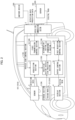
- Fig. 1 is a block diagram illustrating a digital twin system 100.
- Fig. 2 is a block diagram illustrating a functional configuration of a vehicle 101.
- Fig. 3 is a diagram illustrating a trained model used by the digital twin system 100 for prediction.
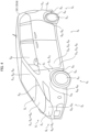
- Fig. 4 is a perspective view illustrating the vehicle 101 and a sensor of the vehicle 101.
- Fig. 5 is a block diagram illustrating a functional configuration of a server 102. Note that reference numerals in parentheses in the drawings indicate reference numerals in Embodiment 2 described later.
- the digital twin system 100 reproduces, in a virtual space, a digital twin indicating a state of the vehicle 101.
- the digital twin system 100 includes a plurality of vehicles 101 and the server 102 as illustrated in Fig. 1 . These are connected to each other via a communication network N.
- the vehicle 101 includes a plurality of types of sensors S, a vehicle side control section 1, a vehicle side communication section 2, a storage section 3, and a display section 4 as illustrated in Fig. 2 .
- the vehicle side communication section 2 transmits and receives, for example, various data and various signals in a wired or wireless manner with another device 200 (e.g., the server 102 described later, a terminal device possessed by or attached to a traffic participant other than the vehicle 101 (a pedestrian or a person on a bicycle), a drone, a road camera C installed on the road, a road sensor S 9 installed on the road, etc.).
- the vehicle side communication section 2 in accordance with the present embodiment is constituted by a communication module.
- the storage section 3 stores a trained model 31.
- the trained model 31 in accordance with the present embodiment is configured to generate prediction data D 2 on the basis of a relatively large number of types of detection data D 1 (as compared with a trained model 31A of Embodiment 2 described later).
- the detection data D 1 includes, as illustrated in a left-hand part of Fig. 3 , prior information D 11 that is set before traveling, event information D 12 that is generated in response to occurrence of an event, and update information D 13 that is periodically updated.
- the prior information D 11 includes, for example, route information of a navigation system.
- the event information D 12 includes, for example, braking information pertaining to braking of the vehicle 101.
- the braking information includes, for example, steering information indicating that a steering wheel has been operated, brake information indicating that a brake has been applied, and blinker information indicating that a blinker has been turned on.
- the update information D 13 includes, for example, a position of the vehicle 101, a speed of the vehicle 101, and acceleration/deceleration of the vehicle 101.
- the update information D 13 may be from the sensors S of the vehicle 101 or may be from the another device 200.
- the prediction data D 2 includes, for example, future traffic information (e.g., the position, etc.) of the vehicle 101.
- the trained model 31 in accordance with the present embodiment is constructed by machine learning (e.g., deep learning) in which training data is a set of (i) the detection data D 1 obtained in the past and (ii) traffic information obtained when the detection data D 1 is obtained or in a situation similar to that when the detection data D 1 is obtained.
- the trained model 31 in accordance with the present embodiment can use such a large number of detection data D 1 to comparatively accurately predict the state of the vehicle 101 in a relatively distant future (as compared with the trained model 31A of Embodiment 2).
- the trained model 31 may be configured to generate other prediction data D 2 different from the prediction data D 2 and serving as a candidate.
- the display section 4 is provided at a position at which a driver of the vehicle 101 can visually recognize the display section 4. Further, the display section 4 displays a screen based on a signal from the vehicle side control section 1.
- the vehicle side control section 1 includes an acquisition section 11, a prediction section 12, a determination section 13, a first transmission control section 14, a first reception control section 15, and an output control section 16 as illustrated in Fig. 2 .
- the acquisition section 11 in accordance with the present embodiment acquires the detection data D 1 from the respective plurality of types of sensors S. Further, the acquisition section 11 in accordance with the present embodiment acquires the detection data D 1 from the respective sensors S via an input IF (not illustrated) to which the sensors S are connected. Furthermore, the acquisition section 11 in accordance with the present embodiment acquires the detection data D 1 from the another device 200. The acquisition section 11 in accordance with the present embodiment acquires the detection data D 1 from the another device 200 via the vehicle side communication section 2. Moreover, the acquisition section 11 in accordance with the present embodiment repeatedly acquires various types of the detection data D 1 every time a certain time period (e.g., 100 msec) has elapsed. The certain time period can be set to any length.
- a certain time period e.g., 100 msec
- the sensors S of the vehicle 101 include, for example, at least one selected from the group consisting of a position (distance/angle) sensor S 1 , a speed sensor S 2 , an acceleration sensor S 3 , a pressure sensor S 4 , a temperature sensor S 5 , a force (torque) sensor S 6 , a flowmeter S 7 , and a gas sensor S 8 as illustrated in Fig. 4 .
- the position (distance/angle) sensor S 1 includes at least one selected from the group consisting of a sensor S 11 that detects a distance from an object present in the front, a sensor S 12 that detects a distance from an object present in the rear, a sensor S 13 that detects a rotation angle of a steering wheel, a sensor S 14 that detects an inclination angle of a throttle valve, a sensor S 15 that detects an inclination angle of an accelerator pedal, and a sensor S 16 that detects an inclination angle of a brake pedal.
- the speed sensor S 2 includes at least one selected from the group consisting of a sensor S 21 that detects a rotation speed of a wheel, a sensor S 22 that detects a speed of a crankshaft, a sensor S 23 that detects a speed of a camshaft, and a sensor S 24 that detects a jet velocity of a jet pump in a diesel engine.
- the acceleration sensor S 3 detects acceleration (impact) acting on a vehicle body.
- the pressure sensor S 4 includes at least one selected from the group consisting of a sensor S 41 that detects a tire pressure, a sensor S 42 that detects a brake pressure, a sensor S 43 that detects a hydraulic reservoir pressure in power steering, a sensor S 44 that detects a suction pressure, a sensor S 45 that detects a charging pressure, a sensor S 46 that detects a fuel pressure, a sensor S 47 that detects a refrigerant pressure in air conditioning, and a sensor S 48 that detects a modulation pressure in an automatic transmission.
- the temperature sensor S 5 includes at least one selected from the group consisting of a sensor S 51 that detects a tire temperature, a sensor S 52 that detects an air supply temperature, a sensor S 53 that detects an ambient temperature, a sensor S 54 that detects an internal temperature, a sensor S 55 that detects an evaporator temperature in air conditioning, a sensor S 56 that detects a coolant temperature, and a sensor S 57 that detects an engine oil temperature.
- the force (torque) sensor S 6 includes at least one selected from the group consisting of a sensor S 61 that detects a pedaling force, a sensor S 62 that detects a body weight of an occupant, a sensor S 63 that detects torque acting on a drive shaft, and a sensor S 64 that detects torque acting on a steering wheel.
- the flowmeter S 7 includes at least one selected from the group consisting of a sensor S 71 that detects a flow rate of fuel and an amount of the fuel supplied to an engine and a sensor S 72 that detects an amount of air sucked by the engine.
- the gas sensor S 8 includes at least one selected from the group consisting of a sensor S 81 that detects a composition of exhaust gas and a sensor S 82 that detects a hazardous substance contained in supplied air.
- the acquisition section 11 may be configured to acquire the detection data D 1 from the respective plurality of vehicles 101.
- the acquisition section 11 may alternatively be configured to acquire, from the vehicle 101 via a storage device (not illustrated), the detection data D 1 (once stored in the storage device).
- the acquisition section 11 may alternatively be configured to acquire the detection data D 1 via a recording medium or the like instead of the vehicle side communication section 2.
- the acquisition section 11 may alternatively be configured to acquire the detection data D 1 from the another device 200 described earlier, for example, the traffic participant other than the vehicle 101, the drone, etc.
- the acquisition section 11 may alternatively be configured to acquire the detection data D 1 via the vehicle side communication section 2 from at least one selected from the group consisting of the road camera C and the road sensor S 9 .
- the acquisition section 11 may alternatively be configured to acquire the detection data D 1 that is route information set in a navigation system of the vehicle 101 or the terminal device.
- the acquisition section 11 may alternatively be configured to acquire the detection data D 1 that is an image(s) captured by an event data recorder and/or a rear view camera of the vehicle 101.
- the acquisition section 11 may alternatively be configured to acquire the detection data D 1 that is information (such as drowsiness of a driver) determined by the vehicle 101 on the basis of the detection data D 1 .
- the prediction section 12 predicts a future state of the vehicle 101 on the basis of the detection data D 1 and outputs a prediction result for the future state as the prediction data D 2 .
- the future refers to, for example, a time after a first certain time period from a time at which the detection data D 1 is acquired.
- the first certain time period can be set to any length (e.g., 500 msec) that exceeds a cycle in which the detection data D 1 is acquired by the acquisition section 11.
- the prediction section 12 uses the trained model 31 stored in the storage section 3 to predict the future.
- the prediction data D 2 includes, for example, a future position of the vehicle 101, etc. As described earlier, the acquisition section 11 repeatedly acquires the detection data D 1 .
- the prediction section 12 in accordance with the present embodiment repeatedly predicts the future state of the vehicle 101 (outputs the prediction data D 2 ). Further, as described earlier, the trained model 31 stored in the storage section 3 in accordance with the present embodiment has a relatively large number (relatively many types) of data to be input. Thus, the prediction section 12 in accordance with the present embodiment outputs the prediction data D 2 indicating a relatively distant future state of the vehicle 101. Note that the prediction section 12 may be configured to output, instead of the prediction data D 2 indicating a state at a certain moment in the future, the prediction data D 2 having a temporal width. The prediction section 12 may alternatively be configured to output, as the prediction data D 2 indicating the state at a certain moment in the future, the prediction data D 2 having a spatiotemporal width.
- the determination section 13 determines whether it is possible to transmit usage information.
- the usage information is information for use by the server 102 described later to carry out a simulation.
- the usage information is information based on either the detection data D 1 or the prediction data D 2 .
- the determination section 13 in accordance with the present embodiment determines, as whether it is possible to transmit information, whether a predicted future (time after the first certain time period) is reached.
- the expression "the future is reached” may indicate that a time immediately before (e.g., several seconds before) the future has been reached, or may indicate that the future has been actually reached.
- the vehicle 101 that includes such a determination section 13 enables quick determination. Further, the determination section 13 in accordance with the present embodiment repeatedly carries out such determination.
- the determination section 13 may be constituted by a timer. Further, in a case where the server 102 described later can use information from a device different from the vehicle 101 to specify the usage information, the determination section 13 may be configured to determine, in response to an instruction from the server 102, whether it is possible to transmit the usage information. Examples of a case where the information from the device different from the vehicle 101 can be used to specify the usage information include a case where the server 102 can directly acquire the detection data D 1 such as position information, a speed, etc. of the vehicle 101 from the road camera C, the road sensor S 9 , etc.
- the first transmission control section 14 controls the vehicle side communication section 2 on the basis of a determination result from the determination section 13. With this, in a case where the determination section 13 determines that the usage information is to be transmitted, the vehicle side communication section 2 wirelessly transmits the usage information to the server 102.
- the vehicle side control section 1 in accordance with the present embodiment includes the prediction section 12 and outputs the prediction data D 2 .
- the vehicle side communication section 2 in accordance with the present embodiment wirelessly transmits, to the server 102, the prediction data D 2 as the usage information. This makes it possible to save time and effort required for prediction of the state of the vehicle 101 by the server 102. As a result, the server 102 can easily generate a digital twin.
- the determination section 13 in accordance with the present embodiment repeatedly carries out determination.
- the vehicle side communication section 2 in accordance with the present embodiment wirelessly transmits subsequent usage information on the basis of a determination result indicating whether it is possible to transmit the subsequent usage information.
- the determination section 13 in accordance with the present embodiment determines, as whether it is possible to transmit information, whether the predicted future is reached.
- the vehicle side communication section 2 in accordance with the present embodiment wirelessly transmits the usage information to the server 102. This makes it unnecessary, during a period until the predicted future is reached, to transmit data to the server 102, so that a volume of communication traffic between the vehicle 101 and the server 102 can be reduced.
- the first transmission control section 14 may control the vehicle side communication section 2 so as to stop transmission of the usage information.
- the first reception control section 15 controls the vehicle side communication section 2 so as to receive a simulation result (digital twin) from the server 102.
- the output control section 16 controls the display section 4 so as to display the simulation result received from the server 102.
- the output control section 16 may control a speaker (not illustrated) so as to output a voice.
- the vehicle 101 may include an operation control section instead of the display section 4 and the output control section 16 or in addition to the display section 4 and the output control section 16.
- the operation control section automatically controls, on the basis of the simulation result received from the server 102, at least some of operations carried out by the vehicle 101. This allows the traffic information to be more quickly provided to the operation control section. Thus, the operation control section can carry out operation with higher safety.
- the server 102 includes a server side control section 5 and a server side communication section 6 as illustrated in Fig. 5 .
- the server side control section 5 includes a second reception control section 51, an execution section 52, and a second transmission control section 53.
- the second reception control section 51 controls the server side communication section 6 so that the server side communication section 6 receives the usage information from the vehicle 101.
- the vehicle side communication section 2 of the vehicle 101 in accordance with the present embodiment wirelessly transmits subsequent usage information in accordance with a determination result that the subsequent usage information is to be transmitted.
- the second reception control section 51 controls the vehicle side communication section 2 so as to receive the subsequent usage information which the vehicle 101 has transmitted in accordance with a determination result that the subsequent usage information is to be transmitted.
- the server side communication section 6 receives the subsequent usage information.
- the execution section 52 carries out a simulation regarding a traffic condition on the basis of the usage information and traffic data of the traffic participant present around the vehicle 101.
- the traffic data is, for example, various data that have been transmitted from the terminal device possessed by or attached to the traffic participant, the drone, the road camera C installed on the road, the road sensor S 9 installed on the road, etc.
- the second reception control section 51 in accordance with the present embodiment receives the prediction data D 2 as the usage information.
- the execution section 52 in accordance with the present embodiment carries out the simulation regarding the traffic condition on the basis of the prediction data D 2 and the traffic data.
- the execution section 52 generates, as a simulation result, a digital twin indicating the future state of the vehicle 101.
- the simulation result may include not only information pertaining to the vehicle 101 but also information pertaining to an environment surrounding the vehicle 101 (for example, information pertaining to another traffic participant, etc.).
- the execution section 52 that can directly acquire detection data D 1 from a device different from the vehicle 101 may be configured to carry out the simulation on the basis of the detection data D 1 instead of the usage information of the vehicle 101.
- the digital twin system 100 may include at least one selected from the group consisting of: a vehicle that has a function to output the usage information but does not have a function to acquire the simulation result; and a vehicle that does not have the function to output the usage information but has the function to acquire the simulation result.
- the vehicle 101 uses the trained model 31 to output the prediction data D 2 indicating the state of the vehicle 101 in a future (T 1t ).
- the certain event include setting of the route information in the navigation system and generation of the detection data D 1 by the various sensors S of the vehicle 101.
- the server 102 that has received the prediction data D 2 carries out a simulation on the basis of the received prediction data D 2 and generates a digital twin indicating the state of the vehicle 101 in the future (at the time Tit).
- the server 102 that has received the prediction data D 2 carries out a simulation on the basis of the received prediction data D 2 and generates a digital twin indicating the state of the vehicle 101 in the future (at the time T 2t ). Thereafter, the vehicle 101 and the server 102 repeat the operation as described earlier every time the future (T31 ...) predicted last time is reached.
- a conventional vehicle is configured to periodically transmit data as illustrated in an upper part of Fig. 7
- the vehicle 101 in accordance with the present embodiment transmits the usage information at longer intervals as compared with the conventional vehicle as illustrated in a lower part of Fig. 7 .
- Fig. 8 is a block diagram illustrating a functional configuration of a server 102A. Note that for convenience, members having functions identical to those of the respective members described in Embodiment 1 are given respective identical reference numerals, and a description of those members is omitted.
- the digital twin system 100 in accordance with Embodiment 1 is configured such that the vehicle 101 predicts the future state of the vehicle, and the server 102 receives the prediction data D 2 from the vehicle 101 and carries out a simulation.
- a digital twin system 100A in accordance with the present embodiment is configured such that both a vehicle 101A and a server 102A predict a future state of the vehicle 101A.
- the digital twin system 100A in accordance with the present embodiment includes a plurality of vehicles 101A and the server 102A as illustrated in Fig. 1 . These are connected to each other via a communication network N.
- the vehicle side storage section 3A stores a trained model 31A.
- the trained model 31A in accordance with the present embodiment is configured to generate prediction data D 2 on the basis of some of detection data D 1 , i.e., a relatively small number of types of the detection data D 1 (as compared with the trained model 31 of Embodiment 1 described above).
- Some of the detection data D 1 include update information D 13 and map information D 14 as illustrated in a right-hand part of Fig. 3 .
- the trained model 31A in accordance with the present embodiment is constructed by machine learning (e.g., deep learning) in which training data is a set of (i) the detection data D 1 obtained in the past and (ii) traffic information obtained when the detection data D 1 is obtained or in a situation similar to that when the detection data D 1 is obtained.
- the trained model 31A in accordance with the present embodiment thus uses, as input, a smaller number of data than in Embodiment 1 to predict a state of the vehicle 101A in a relatively near future (as compared with the trained model 31 of Embodiment 1).
- the relatively near future refers to, for example, a time after a second certain time period from a time at which the detection data D 1 is acquired.
- the second certain time period can be set to any length (e.g., 300 msec) that exceeds a cycle in which the detection data D 1 is generated but does not exceed the first certain time period.
- the state (prediction data D 2 ) of the vehicle 101A in a near future which state is output by the trained model 31A in accordance with the present embodiment serves as a predicted value of the detection data D 1 after the second certain time period, the predicted value corresponding to the input detection data D 1 .
- the trained model 31A may be configured to generate other prediction data D 2 different from the prediction data D 2 and serving as a candidate.
- the vehicle side control section 1A includes not only an acquisition section 11, a first reception control section 15, and an output control section 16 but also a vehicle side prediction section 12A, a determination section 13A, and a first transmission control section 14A as illustrated in Fig. 2 .
- the vehicle side prediction section 12A in accordance with the present embodiment uses the trained model 31A to predict a future state of the vehicle 101A on the basis of some of the detection data D 1 and outputs a prediction result for the future state as the prediction data D 2 .
- the prediction data D 2 includes, for example, a future position of the vehicle 101A, etc.
- the vehicle side prediction section 12A uses the trained model 31A stored in the vehicle side storage section 3A to predict a future.
- the trained model 31A stored in the vehicle side storage section 3A in accordance with the present embodiment uses, as input, a smaller number (fewer types) of the detection data D 1 than the trained model 31 in accordance with Embodiment 1.
- the vehicle side prediction section 12A in accordance with the present embodiment carries out prediction by inputting, into the trained model 31A, the detection data D 1 identical to that to be transmitted to the server 102A.
- the vehicle side prediction section 12A inputs, into the trained model 31A, the prediction data D 2 that the vehicle side prediction section 12A predicted last time. That is, the vehicle side prediction section 12A in accordance with the present embodiment repeats prediction in a certain cycle.
- one of the repeatedly output prediction data D 2 which one is input into the trained model 31A is referred to as predictive detection data D 3 .
- the determination section 13A in accordance with the present embodiment includes a comparison section 131.
- the comparison section 131 compares the future state of the vehicle 101A which future state is based on the prediction data D 2 with a current state of the vehicle 101A which current state is based on the detection data D 1 immediately after acquisition of the detection data D 1 .
- the determination section 13A in accordance with the present embodiment compares the prediction data D 2 with the detection data D 1 .
- the determination section 13A in accordance with the present example embodiment determines, as whether it is possible to transmit usage information, whether an error which is not less than a threshold has occurred between the future state and the current state.
- the vehicle 101A travels approximately 1.3 m during 80 msec.
- the difference in a case where a difference between a predicted future position and an actually reached position is less than 1.3 m, it is determined that the difference is an allowable error.
- the difference in a case where the difference is not less than 1.3 m, it is determined that the difference is an unacceptable error.
- Usage information in accordance with the present embodiment constitutes part of the detection data D 1 .
- the determination section 13A in accordance with the present example embodiment determines, as whether it is possible to transmit information, whether the error which is not less than the threshold has occurred between the future state and the current state.
- the vehicle side communication section 2 in accordance with the present embodiment wirelessly transmits the usage information to the server 102A. This makes it unnecessary, during a period until the predicted future is reached, to transmit data to the server 102A, so that a volume of communication traffic between the vehicle 101A and the server 102A can be reduced.
- the first transmission control section 14A may control the vehicle side communication section 2 so as to stop transmission of the usage information.
- determination section 13A may be configured to determine, as whether it is possible to transmit the usage information, whether the predicted future is reached.
- the first transmission control section 14A controls the vehicle side communication section 2 on the basis of a determination result from the determination section 13A. With this, in a case where the determination section 13A determines that the error which is not less than the threshold has occurred, the vehicle side communication section 2 wirelessly transmits, to the server 102A, some of new detection data D 1 acquired by the acquisition section 11.
- the first transmission control section 14A in accordance with the present embodiment controls the vehicle side communication section 2 so that the vehicle side communication section 2 wirelessly transmits, to the server 102A, some of a plurality of the detection data D 1 as the usage information. This makes it possible to operate another device that operates on the basis of the detection data D 1 (for example, the server 102A that carries out future prediction based on the detection data D 1 ).
- the vehicle side prediction section 12A While the determination section 13A is determining that the error which is not less than the threshold has not occurred, the vehicle side prediction section 12A repeatedly outputs the prediction data D 2 . Note, however, that the first transmission control section 14A does not control the vehicle side communication section 2 so as to transmit the prediction data D 2 to the server 102A.
- the first transmission control section 14A may be configured to control the vehicle side communication section 2 so that, while the determination section 13A is determining that an error which has occurred between the future state and the current state is less than the threshold, the vehicle side communication section 2 does not transmit a prediction result for the future state of the vehicle 101A to the server 102A even in a case where the vehicle side prediction section 12A predicts the future state of the vehicle 101A.
- the server 102A in accordance with the present embodiment includes not only a server side communication section 6 but also a server side control section 5A and a server side storage section 7 as illustrated in Fig. 8 .
- the server side storage section 7 stores a trained model 71.
- the trained model 71 in accordance with the present embodiment is similar to the trained model 31A stored in the vehicle side storage section 3A.
- the server side control section 5A includes not only a second transmission control section 53 but also a second reception control section 51A, an execution section 52A, and a server side prediction section 54.
- the second reception control section 51A in accordance with the present embodiment controls the server side communication section 6 so as to receive, for example, various data and various signals from the vehicle 101A.
- the vehicle 101A in accordance with the present embodiment transmits some of the detection data D 1 as the usage information to the server 102A.
- the server side communication section 6 receives some of the plurality of the detection data D 1 as the usage information.
- the second reception control section 51A in accordance with the present embodiment controls the server side communication section 6 so as to receive the detection data D 1 from another device (the road camera C, the road sensor S 9 , etc.).
- the server side prediction section 54 predicts the state of the vehicle 101A in the relatively near future (after the second certain time period from the time at which the detection data D 1 is acquired) on the basis of some of the detection data D 1 , and outputs a prediction result for the state of the vehicle 101A as the prediction data D 2 . This makes it possible to reduce a burden on the vehicle 101A and make a comparison with the prediction data D 2 on the vehicle 101A side.
- the server side prediction section 54 in accordance with the present embodiment repeats prediction in a cycle identical to the cycle in which the vehicle side prediction section 12A of the vehicle 101A repeats prediction.
- the server side prediction section 54 in accordance with the present embodiment carries out prediction by inputting, into the trained model 71, the detection data D 1 that has been received from the vehicle 101A.
- the server side prediction section 54 carries out prediction by inputting, into the trained model 71, the predictive detection data D 3 that is the prediction data D 2 which the server side prediction section 54 predicted last time. This allows the server side prediction section 54 to input data into the trained model 71 also at a time different from when the detection data D 1 is received from the vehicle 101A, so that the server side prediction section 54 can carry out prediction in synchronization with the vehicle side prediction section 12A.
- the execution section 52A carries out a simulation regarding a traffic condition on the basis of the prediction data D 2 output by the server side prediction section 54 and data on a traffic participant.
- the vehicle side prediction section 12A of the vehicle 101A uses the trained model 31A to output the prediction data D 2 as illustrated in Fig. 9 .
- the vehicle 101A immediately transmits, to the server 102A, the detection data D 1 that has been used to output the prediction data D 2 (T 11 ). Thereafter, the vehicle 101A compares the future state of the vehicle 101A which future state is based on the prediction data D 2 with a current state of the vehicle 101A which current state is based on the detection data D 1 immediately after acquisition of the detection data D 1 (T 12 , T 13 , ).
- the server 102A that has received the detection data D 1 stops prediction which has been carried out so far with use of the predictive detection data D 3 , and outputs the prediction data D 2 which is based on the received detection data D 1 .
- the server 102A carries out a simulation on the basis of the output prediction data D 2 and generates a digital twin indicating the future state of the vehicle 101A.
- the vehicle 101A uses the trained model 31A again to output the prediction data D 2 indicating the future state of the vehicle 101A.
- the vehicle 101A immediately transmits, to the server 102A, the detection data D 1 that has been used to output the prediction data D 2 (T 21 ).
- the vehicle 101A compares the future state of the vehicle 101A with the current state of the vehicle 101A (T 22 , T 23 , ).
- the vehicle 101A transmits no detection data D 1 until it is determined that the error T h , -T h which is not less than the threshold has occurred between the future state and the current state.
- the vehicle 101A outputs the prediction data D 2 in a certain cycle until it is determined that the error Th, -Th which is not less than the threshold has occurred, and uses the prediction data D 2 as the predictive detection data D 3 for subsequent prediction.
- the server 102A that has received the detection data D 1 stops prediction which has been carried out so far with use of the predictive detection data D 3 , and outputs the prediction data D 2 which is based on the received detection data D 1 .
- the server 102A carries out a simulation on the basis of the output prediction data D 2 and generates a digital twin indicating the future state of the vehicle 101A. Thereafter, the vehicle 101A and the server 102A repeat the operation as described above every time the error T h , -T h which is not less than the threshold occurs between the future state and the current state.
- a conventional vehicle is configured to periodically transmit data as illustrated in the upper part of Fig. 7 , whereas the vehicle 101A in accordance with the present embodiment transmits the usage information at longer intervals as compared with the conventional vehicle as illustrated in the lower part of Fig. 7 .
- some of the detection data D 1 is transmitted as the usage information to the server 102A, and the future state of the vehicle 101A is predicted on each of the vehicle 101A side and the server 102A side.
- Some of data has a data volume that is smaller than a total volume of all the detection data D 1 . This allows the server 102A to carry out the simulation with a smaller data volume than a conventional server. Further, since the prediction data D 2 output by the vehicle 101A and the prediction data D 2 output by the server 102A are updated before an error therebetween reaches a value that is not less than a predetermined value, the server 102A can reproduce a digital twin with high accuracy.
- the digital twin system 100A including the vehicle 101A and the server 102A that generates a digital twin of the vehicle 101A, a reduction in volume of communication traffic between the vehicle 101A and the server 102A can be achieved without a decrease in accuracy of the digital twin.
- the vehicle 101A and the server 102A in accordance with the present embodiment reuse, as input, respective outputs (predictive detection data D 3 ) of the prediction sections 12A and 54 during a period until it is determined that the error which is not less than the threshold has occurred between the future state and the current state, and make short-cycle transmission unnecessary by transmitting no detection data D 1 during that period.
- the vehicle 101A and the server 102A in accordance with the present embodiment make it possible both to prevent or reduce a volume of communication traffic and to achieve highly accurate prediction.
- All or part of the functions of the control blocks can be realized by a logic circuit.
- the present invention encompasses, in its scope, an integrated circuit in which a logic circuit that functions as each of the control blocks is formed.
- the functions of the control blocks can be realized by, for example, a quantum computer.
- the functions of the vehicles 101 and 101A and the servers 102 and 102A can be realized by a program for causing a computer to function as the device, etc., the program causing the computer to function as the control blocks (in particular, the sections included in the vehicle side control sections 1 and 1A and the server side control sections 5 and 5A) of the device.
- the device includes, as hardware for executing the program, a computer that includes at least one control device (e.g., a processor) and at least one storage device (e.g., a memory).
- the functions described in the foregoing embodiments are realized by executing the program with use of the control device and the storage device.
- the program may be recorded in one or more non-transitory computer-readable recording media.
- the one or more recording media may or may not be included in the device. In the latter case, the program may be made available to the device via any wired or wireless transmission medium.
- the present invention is not limited to the embodiments, but can be altered by a skilled person in the art within the scope of the claims.
- the present invention also encompasses, in its technical scope, any embodiment derived by combining technical means disclosed in differing embodiments.
Landscapes
- Engineering & Computer Science (AREA)
- Physics & Mathematics (AREA)
- General Physics & Mathematics (AREA)
- Theoretical Computer Science (AREA)
- Software Systems (AREA)
- Evolutionary Computation (AREA)
- Artificial Intelligence (AREA)
- Life Sciences & Earth Sciences (AREA)
- General Engineering & Computer Science (AREA)
- Atmospheric Sciences (AREA)
- Medical Informatics (AREA)
- Mathematical Physics (AREA)
- Analytical Chemistry (AREA)
- Chemical & Material Sciences (AREA)
- Data Mining & Analysis (AREA)
- Computing Systems (AREA)
- Computer Vision & Pattern Recognition (AREA)
- Mechanical Engineering (AREA)
- Transportation (AREA)
- Computer Networks & Wireless Communication (AREA)
- Human Computer Interaction (AREA)
- Signal Processing (AREA)
- Automation & Control Theory (AREA)
- Health & Medical Sciences (AREA)
- Molecular Biology (AREA)
- General Health & Medical Sciences (AREA)
- Computer Hardware Design (AREA)
- Geometry (AREA)
- Computational Linguistics (AREA)
- Biophysics (AREA)
- Biomedical Technology (AREA)
- Traffic Control Systems (AREA)
Abstract
Description
- The present invention relates to a vehicle and a server.
- A technique related to a digital twin system is conventionally known. The digital twin system reproduces a state of a vehicle in a virtual space on the basis of detection data output by various sensors of the vehicle. For example,
Patent Literature 1 discloses a method including the steps of: generating a digital twin of a vehicle; receiving digital data that is recorded by a sensor and that describes a state of the vehicle which is present in a real world and behavior of the vehicle which is traveling in the real world; and updating the digital twin of the vehicle on the basis of the digital data so that the digital twin matches the state and the behavior. - [Patent Literature 1]
Japanese Patent Application Publication Tokukai No. 2020-013557 - In a digital twin system, as a state of a vehicle is to be reproduced with higher accuracy, a server that generates a virtual space requires more real-time information pertaining to the state of the vehicle. However, according to such a conventional technique as described above, an increase in reproduction accuracy results in an increase in volume of communication traffic between the vehicle and the server. This may make it impossible to transmit sufficient data to the server. In contrast, an attempt to prevent or reduce the volume of communication traffic between the vehicle and the server causes the state of the vehicle to be reproduced in the virtual space with lower accuracy.
- In order to solve the problem, a vehicle in accordance with an aspect of the present invention includes:
- a plurality of sensors;
- an acquisition section that acquires detection data from the respective plurality of sensors;
- a prediction section that uses a trained model constructed by machine learning to predict a future state of the vehicle on the basis of the detection data and that outputs a prediction result for the future state as prediction data; and
- a communication section that transmits, to a server, usage information which is based on either the detection data or the prediction data and which is for use in a simulation,
- after transmitting the usage information, the communication section transmitting subsequent usage information on the basis of a determination result indicating whether it is possible to transmit the subsequent usage information.
- In order to solve the problem, a server in accordance with another aspect of the present invention includes:
- a communication section that receives, from a vehicle including a plurality of sensors, an acquisition section which acquires detection data from the respective plurality of sensors, and a prediction section which uses a trained model constructed by machine learning to predict a future state of the vehicle on the basis of the detection data, usage information which is based on either the detection data output by the plurality of sensors or prediction data output by the prediction section and which is necessary for a simulation; and
- an execution section that carries out a simulation regarding a traffic condition on the basis of the usage information and traffic data of a traffic participant present around the vehicle,
- after receiving the usage information, the communication section receiving subsequent usage information which the vehicle has transmitted in accordance with a determination result that the subsequent usage information is to be transmitted.
-
-
Fig. 1 is a block diagram illustrating a digital twin system constituted by a vehicle and a server in accordance withEmbodiments -
Fig. 2 is a block diagram illustrating a functional configuration of the vehicle of the digital twin system. -
Fig. 3 is a diagram illustrating a trained model used by the digital twin system for prediction. -
Fig. 4 is a perspective view illustrating the vehicle and a sensor of the vehicle. -
Fig. 5 is a block diagram illustrating a functional configuration of the server in accordance withEmbodiment 1. -
Fig. 6 is a timing diagram illustrating an operation by a digital twin system in accordance withEmbodiment 1. -
Fig. 7 is a view describing some of effects of the present invention. -
Fig. 8 is a block diagram illustrating a functional configuration of a server in accordance withEmbodiment 2 of an aspect of the present invention. -
Fig. 9 is a timing diagram illustrating an operation by a digital twin system in accordance withEmbodiment 2. - First, the following description will discuss
Embodiment 1 of the present invention in detail.Fig. 1 is a block diagram illustrating adigital twin system 100.Fig. 2 is a block diagram illustrating a functional configuration of avehicle 101.Fig. 3 is a diagram illustrating a trained model used by thedigital twin system 100 for prediction.Fig. 4 is a perspective view illustrating thevehicle 101 and a sensor of thevehicle 101.Fig. 5 is a block diagram illustrating a functional configuration of aserver 102. Note that reference numerals in parentheses in the drawings indicate reference numerals inEmbodiment 2 described later. - The
digital twin system 100 reproduces, in a virtual space, a digital twin indicating a state of thevehicle 101. Thedigital twin system 100 includes a plurality ofvehicles 101 and theserver 102 as illustrated inFig. 1 . These are connected to each other via a communication network N. - The
vehicle 101 includes a plurality of types of sensors S, a vehicleside control section 1, a vehicleside communication section 2, astorage section 3, and adisplay section 4 as illustrated inFig. 2 . - The vehicle
side communication section 2 transmits and receives, for example, various data and various signals in a wired or wireless manner with another device 200 (e.g., theserver 102 described later, a terminal device possessed by or attached to a traffic participant other than the vehicle 101 (a pedestrian or a person on a bicycle), a drone, a road camera C installed on the road, a road sensor S9 installed on the road, etc.). The vehicleside communication section 2 in accordance with the present embodiment is constituted by a communication module. - The
storage section 3 stores a trainedmodel 31. The trainedmodel 31 in accordance with the present embodiment is configured to generate prediction data D2 on the basis of a relatively large number of types of detection data D1 (as compared with a trainedmodel 31A ofEmbodiment 2 described later). The detection data D1 includes, as illustrated in a left-hand part ofFig. 3 , prior information D11 that is set before traveling, event information D12 that is generated in response to occurrence of an event, and update information D13 that is periodically updated. The prior information D11 includes, for example, route information of a navigation system. The event information D12 includes, for example, braking information pertaining to braking of thevehicle 101. The braking information includes, for example, steering information indicating that a steering wheel has been operated, brake information indicating that a brake has been applied, and blinker information indicating that a blinker has been turned on. The update information D13 includes, for example, a position of thevehicle 101, a speed of thevehicle 101, and acceleration/deceleration of thevehicle 101. The update information D13 may be from the sensors S of thevehicle 101 or may be from the anotherdevice 200. The prediction data D2 includes, for example, future traffic information (e.g., the position, etc.) of thevehicle 101. - The trained
model 31 in accordance with the present embodiment is constructed by machine learning (e.g., deep learning) in which training data is a set of (i) the detection data D1 obtained in the past and (ii) traffic information obtained when the detection data D1 is obtained or in a situation similar to that when the detection data D1 is obtained. The trainedmodel 31 in accordance with the present embodiment can use such a large number of detection data D1 to comparatively accurately predict the state of thevehicle 101 in a relatively distant future (as compared with the trainedmodel 31A of Embodiment 2). Note that the trainedmodel 31 may be configured to generate other prediction data D2 different from the prediction data D2 and serving as a candidate. - The
display section 4 is provided at a position at which a driver of thevehicle 101 can visually recognize thedisplay section 4. Further, thedisplay section 4 displays a screen based on a signal from the vehicleside control section 1. - The vehicle
side control section 1 includes anacquisition section 11, aprediction section 12, adetermination section 13, a firsttransmission control section 14, a firstreception control section 15, and anoutput control section 16 as illustrated inFig. 2 . - The
acquisition section 11 in accordance with the present embodiment acquires the detection data D1 from the respective plurality of types of sensors S. Further, theacquisition section 11 in accordance with the present embodiment acquires the detection data D1 from the respective sensors S via an input IF (not illustrated) to which the sensors S are connected. Furthermore, theacquisition section 11 in accordance with the present embodiment acquires the detection data D1 from the anotherdevice 200. Theacquisition section 11 in accordance with the present embodiment acquires the detection data D1 from the anotherdevice 200 via the vehicleside communication section 2. Moreover, theacquisition section 11 in accordance with the present embodiment repeatedly acquires various types of the detection data D1 every time a certain time period (e.g., 100 msec) has elapsed. The certain time period can be set to any length. - The sensors S of the
vehicle 101 include, for example, at least one selected from the group consisting of a position (distance/angle) sensor S1, a speed sensor S2, an acceleration sensor S3, a pressure sensor S4, a temperature sensor S5, a force (torque) sensor S6, a flowmeter S7, and a gas sensor S8 as illustrated inFig. 4 . - The position (distance/angle) sensor S1 includes at least one selected from the group consisting of a sensor S11 that detects a distance from an object present in the front, a sensor S12 that detects a distance from an object present in the rear, a sensor S13 that detects a rotation angle of a steering wheel, a sensor S14 that detects an inclination angle of a throttle valve, a sensor S15 that detects an inclination angle of an accelerator pedal, and a sensor S16 that detects an inclination angle of a brake pedal.
- The speed sensor S2 includes at least one selected from the group consisting of a sensor S21 that detects a rotation speed of a wheel, a sensor S22 that detects a speed of a crankshaft, a sensor S23 that detects a speed of a camshaft, and a sensor S24 that detects a jet velocity of a jet pump in a diesel engine.
- The acceleration sensor S3 detects acceleration (impact) acting on a vehicle body.
- The pressure sensor S4 includes at least one selected from the group consisting of a sensor S41 that detects a tire pressure, a sensor S42 that detects a brake pressure, a sensor S43 that detects a hydraulic reservoir pressure in power steering, a sensor S44 that detects a suction pressure, a sensor S45 that detects a charging pressure, a sensor S46 that detects a fuel pressure, a sensor S47 that detects a refrigerant pressure in air conditioning, and a sensor S48 that detects a modulation pressure in an automatic transmission.
- The temperature sensor S5 includes at least one selected from the group consisting of a sensor S51 that detects a tire temperature, a sensor S52 that detects an air supply temperature, a sensor S53 that detects an ambient temperature, a sensor S54 that detects an internal temperature, a sensor S55 that detects an evaporator temperature in air conditioning, a sensor S56 that detects a coolant temperature, and a sensor S57 that detects an engine oil temperature.
- The force (torque) sensor S6 includes at least one selected from the group consisting of a sensor S61 that detects a pedaling force, a sensor S62 that detects a body weight of an occupant, a sensor S63 that detects torque acting on a drive shaft, and a sensor S64 that detects torque acting on a steering wheel.
- The flowmeter S7 includes at least one selected from the group consisting of a sensor S71 that detects a flow rate of fuel and an amount of the fuel supplied to an engine and a sensor S72 that detects an amount of air sucked by the engine.
- The gas sensor S8 includes at least one selected from the group consisting of a sensor S81 that detects a composition of exhaust gas and a sensor S82 that detects a hazardous substance contained in supplied air.
- Note that the above-listed various sensors S are publicly known as disclosed in, for example, the following Web pages:
- · Vehicle sensors functions and types https://innovationdiscoveries.space/vehicle-sensors-functions-and-types/
- · Automotive sensors: the design engineer's guide https://www.avnet.com/wps/portal/abacus/solutions/m arkets/automotive-and-transportation/automotive/communications-and-connectivity/automotive-sensors/
- Note that the
acquisition section 11 may be configured to acquire the detection data D1 from the respective plurality ofvehicles 101. Theacquisition section 11 may alternatively be configured to acquire, from thevehicle 101 via a storage device (not illustrated), the detection data D1 (once stored in the storage device). Theacquisition section 11 may alternatively be configured to acquire the detection data D1 via a recording medium or the like instead of the vehicleside communication section 2. Theacquisition section 11 may alternatively be configured to acquire the detection data D1 from the anotherdevice 200 described earlier, for example, the traffic participant other than thevehicle 101, the drone, etc. Theacquisition section 11 may alternatively be configured to acquire the detection data D1 via the vehicleside communication section 2 from at least one selected from the group consisting of the road camera C and the road sensor S9. Theacquisition section 11 may alternatively be configured to acquire the detection data D1 that is route information set in a navigation system of thevehicle 101 or the terminal device. Theacquisition section 11 may alternatively be configured to acquire the detection data D1 that is an image(s) captured by an event data recorder and/or a rear view camera of thevehicle 101. Theacquisition section 11 may alternatively be configured to acquire the detection data D1 that is information (such as drowsiness of a driver) determined by thevehicle 101 on the basis of the detection data D1. - The
prediction section 12 predicts a future state of thevehicle 101 on the basis of the detection data D1 and outputs a prediction result for the future state as the prediction data D2. The future refers to, for example, a time after a first certain time period from a time at which the detection data D1 is acquired. The first certain time period can be set to any length (e.g., 500 msec) that exceeds a cycle in which the detection data D1 is acquired by theacquisition section 11. Theprediction section 12 uses the trainedmodel 31 stored in thestorage section 3 to predict the future. The prediction data D2 includes, for example, a future position of thevehicle 101, etc. As described earlier, theacquisition section 11 repeatedly acquires the detection data D1. Thus, theprediction section 12 in accordance with the present embodiment repeatedly predicts the future state of the vehicle 101 (outputs the prediction data D2). Further, as described earlier, the trainedmodel 31 stored in thestorage section 3 in accordance with the present embodiment has a relatively large number (relatively many types) of data to be input. Thus, theprediction section 12 in accordance with the present embodiment outputs the prediction data D2 indicating a relatively distant future state of thevehicle 101. Note that theprediction section 12 may be configured to output, instead of the prediction data D2 indicating a state at a certain moment in the future, the prediction data D2 having a temporal width. Theprediction section 12 may alternatively be configured to output, as the prediction data D2 indicating the state at a certain moment in the future, the prediction data D2 having a spatiotemporal width. - The
determination section 13 determines whether it is possible to transmit usage information. The usage information is information for use by theserver 102 described later to carry out a simulation. The usage information is information based on either the detection data D1 or the prediction data D2. Thedetermination section 13 in accordance with the present embodiment determines, as whether it is possible to transmit information, whether a predicted future (time after the first certain time period) is reached. The expression "the future is reached" may indicate that a time immediately before (e.g., several seconds before) the future has been reached, or may indicate that the future has been actually reached. Thevehicle 101 that includes such adetermination section 13 enables quick determination. Further, thedetermination section 13 in accordance with the present embodiment repeatedly carries out such determination. Note that thedetermination section 13 may be constituted by a timer. Further, in a case where theserver 102 described later can use information from a device different from thevehicle 101 to specify the usage information, thedetermination section 13 may be configured to determine, in response to an instruction from theserver 102, whether it is possible to transmit the usage information. Examples of a case where the information from the device different from thevehicle 101 can be used to specify the usage information include a case where theserver 102 can directly acquire the detection data D1 such as position information, a speed, etc. of thevehicle 101 from the road camera C, the road sensor S9, etc. - The first
transmission control section 14 controls the vehicleside communication section 2 on the basis of a determination result from thedetermination section 13. With this, in a case where thedetermination section 13 determines that the usage information is to be transmitted, the vehicleside communication section 2 wirelessly transmits the usage information to theserver 102. As described earlier, the vehicleside control section 1 in accordance with the present embodiment includes theprediction section 12 and outputs the prediction data D2. Thus, the vehicleside communication section 2 in accordance with the present embodiment wirelessly transmits, to theserver 102, the prediction data D2 as the usage information. This makes it possible to save time and effort required for prediction of the state of thevehicle 101 by theserver 102. As a result, theserver 102 can easily generate a digital twin. - Further, as described earlier, the
determination section 13 in accordance with the present embodiment repeatedly carries out determination. Thus, after transmitting the usage information, the vehicleside communication section 2 in accordance with the present embodiment wirelessly transmits subsequent usage information on the basis of a determination result indicating whether it is possible to transmit the subsequent usage information. - Furthermore, as described earlier, the
determination section 13 in accordance with the present embodiment determines, as whether it is possible to transmit information, whether the predicted future is reached. Thus, in a case where thedetermination section 13 determines that the predicted future is reached, the vehicleside communication section 2 in accordance with the present embodiment wirelessly transmits the usage information to theserver 102. This makes it unnecessary, during a period until the predicted future is reached, to transmit data to theserver 102, so that a volume of communication traffic between thevehicle 101 and theserver 102 can be reduced. Note that, in a case where theserver 102 can directly acquire the detection data D1 from the road camera C, the road sensor S9, etc., the firsttransmission control section 14 may control the vehicleside communication section 2 so as to stop transmission of the usage information. - The first
reception control section 15 controls the vehicleside communication section 2 so as to receive a simulation result (digital twin) from theserver 102. - The
output control section 16 controls thedisplay section 4 so as to display the simulation result received from theserver 102. Theoutput control section 16 may control a speaker (not illustrated) so as to output a voice. - Note that the vehicle
side control section 1 may include a comparison section 131 (seeEmbodiment 2 described later) that compares the future state of thevehicle 101 which future state is based on the prediction data D2 with a current state of thevehicle 101 which current state is based on the detection data D1 immediately after acquisition of the detection data D1. In this case, thedetermination section 13 may be configured to determine, as whether it is possible to transmit the usage information, whether an error which is not less than a threshold set in advance has occurred between the future state and the current state. Further, in this case, the vehicleside communication section 2 may be configured to, in a case where thedetermination section 13 determines that the error which is not less than the threshold has occurred, wirelessly transmit, to theserver 102, new prediction data D2 output by theprediction section 12. - Furthermore, in this case, the first
transmission control section 14 may be configured to control the vehicleside communication section 2 so that, while thedetermination section 13 is determining that an error which has occurred between the future state and the current state is less than the threshold, the vehicleside communication section 2 does not transmit a prediction result for the future state of thevehicle 101 to theserver 102 even in a case where theprediction section 12 predicts the future state of thevehicle 101. Alternatively, theprediction section 12 may be configured such that, while thedetermination section 13 is determining that the error which has occurred between the future state and the current state is less than the threshold, theprediction section 12 does not predict the future state of thevehicle 101. - During a period until the error reaches the threshold or more, the usage information (prediction data D2) is not transmitted to the
server 102. Further, unless thevehicle 101 carries out quite extreme operation, it takes a certain amount of time for the error which occurs between the future state and the current state to reach the threshold or more. Thus, the above-described configuration makes it possible to reduce the volume of communication traffic between thevehicle 101 and theserver 102 as compared with a conventional case where transmission of usage information is periodically repeated. - Further, the
vehicle 101 may include an operation control section instead of thedisplay section 4 and theoutput control section 16 or in addition to thedisplay section 4 and theoutput control section 16. The operation control section automatically controls, on the basis of the simulation result received from theserver 102, at least some of operations carried out by thevehicle 101. This allows the traffic information to be more quickly provided to the operation control section. Thus, the operation control section can carry out operation with higher safety. - The
server 102 includes a serverside control section 5 and a serverside communication section 6 as illustrated inFig. 5 . - The server
side communication section 6 transmits and receives, for example, various data and various signals in a wired or wireless manner with another device (e.g., thevehicle 101, the terminal device possessed by the traffic participant other than thevehicle 101, the drone, the road camera C, the road sensor S9, etc.). The serverside communication section 6 in accordance with the present embodiment is constituted by a communication module. - The server
side control section 5 includes a secondreception control section 51, anexecution section 52, and a secondtransmission control section 53. - The second
reception control section 51 controls the serverside communication section 6 so that the serverside communication section 6 receives the usage information from thevehicle 101. As described earlier, after wirelessly transmitting the usage information, the vehicleside communication section 2 of thevehicle 101 in accordance with the present embodiment wirelessly transmits subsequent usage information in accordance with a determination result that the subsequent usage information is to be transmitted. Thus, after receiving the usage information, the secondreception control section 51 controls the vehicleside communication section 2 so as to receive the subsequent usage information which thevehicle 101 has transmitted in accordance with a determination result that the subsequent usage information is to be transmitted. Thus, after receiving the usage information, the serverside communication section 6 receives the subsequent usage information. - Further, as described earlier, the vehicle
side communication section 2 of thevehicle 101 in accordance with the present embodiment is configured to wirelessly transmit the prediction data D2 as the usage information. Thus, the serverside communication section 6 receives the prediction data D2 as the usage information. - The
execution section 52 carries out a simulation regarding a traffic condition on the basis of the usage information and traffic data of the traffic participant present around thevehicle 101. The traffic data is, for example, various data that have been transmitted from the terminal device possessed by or attached to the traffic participant, the drone, the road camera C installed on the road, the road sensor S9 installed on the road, etc. As described earlier, the secondreception control section 51 in accordance with the present embodiment receives the prediction data D2 as the usage information. Thus, theexecution section 52 in accordance with the present embodiment carries out the simulation regarding the traffic condition on the basis of the prediction data D2 and the traffic data. As a result, theexecution section 52 generates, as a simulation result, a digital twin indicating the future state of thevehicle 101. This makes it possible to carry out the simulation without generation of the prediction data D2 by theserver 102. As a result, it is possible to reduce a burden on theserver 102. Note that the simulation result may include not only information pertaining to thevehicle 101 but also information pertaining to an environment surrounding the vehicle 101 (for example, information pertaining to another traffic participant, etc.). Further, theexecution section 52 that can directly acquire detection data D1 from a device different from thevehicle 101 may be configured to carry out the simulation on the basis of the detection data D1 instead of the usage information of thevehicle 101. - The second
transmission control section 53 controls the serverside communication section 6 in a case where theexecution section 52 carries out the simulation. This allows the serverside communication section 6 to wirelessly transmit, to at least one selected from the group consisting of thevehicle 101 and the terminal device possessed by the traffic participant, a result of the simulation carried out by theexecution section 52. This allows an occupant (traffic participant) of thevehicle 101 to be aware, by seeing the simulation result displayed on the display section 4 (display section of the terminal device), in what situation the occupant may be placed in the future. As a result, the occupant (traffic participant) of thevehicle 101 can drive (move) very safely with attention paid to a situation of which the occupant has been made aware. Further, such a configuration allows urban and human residential areas to be safe. This makes it possible to contribute to achievement ofGoal 11 "Make cities and human settlements inclusive, safe, resilient and sustainable." of Sustainable Development Goals (SDGs). - The
digital twin system 100 may include at least one selected from the group consisting of: a vehicle that has a function to output the usage information but does not have a function to acquire the simulation result; and a vehicle that does not have the function to output the usage information but has the function to acquire the simulation result. - In a case where a certain event occurs in the
vehicle 101 constituting thedigital twin system 100, as illustrated inFig. 6 , thevehicle 101 uses the trainedmodel 31 to output the prediction data D2 indicating the state of thevehicle 101 in a future (T1t). Examples of the certain event include setting of the route information in the navigation system and generation of the detection data D1 by the various sensors S of thevehicle 101. Thevehicle 101 that has generated the detection data D1 uses, as a cycle, a time difference DT (T1h)-DT (T1n-1) (n=1 to t) identical to a cycle in which the detection data D1 has been generated to repeatedly predict a future DT (T1n) of thevehicle 101 at each time T until a time T1t is reached. Thevehicle 101 collectively outputs, as the prediction data D2, the future DT (T1n) of thevehicle 101 at each time from T11 to T1t which future has been obtained by prediction, and immediately transmits the prediction data D2 to the server 102 (T11). The first certain time period described earlier is a sum of time differences DT (T1n)-DT (T1n-1) in the prediction data D2. A conventional vehicle repeats communication with theserver 102 also thereafter (T12, T13, ...), whereas thevehicle 101 does not transmit the prediction data D2 (though carrying out future prediction itself) until it is determined that the predicted future (T1t) is reached. Note that the first certain time period can also be considered to be a cycle in which the prediction data D2 is output, and is longer than both a cycle in which the detection data D1 is generated and a cycle in which the trainedmodel 31 carries out prediction. - The
server 102 that has received the prediction data D2 carries out a simulation on the basis of the received prediction data D2 and generates a digital twin indicating the state of thevehicle 101 in the future (at the time Tit). - In a case where the future (T1t) predicted last time (here, a time (T21) immediately before the future (T1t) predicted last time) is reached, the
vehicle 101 uses the trainedmodel 31 again to output the prediction data D2 indicating the state of thevehicle 101 in a future (T2t). Thevehicle 101 immediately transmits the output prediction data D2 to the server 102 (T21). Thevehicle 101 does not transmit the prediction data D2 until it is determined that the predicted future (T2t) is reached. - The
server 102 that has received the prediction data D2 carries out a simulation on the basis of the received prediction data D2 and generates a digital twin indicating the state of thevehicle 101 in the future (at the time T2t). Thereafter, thevehicle 101 and theserver 102 repeat the operation as described earlier every time the future (T31 ...) predicted last time is reached. As a result, a conventional vehicle is configured to periodically transmit data as illustrated in an upper part ofFig. 7 , whereas thevehicle 101 in accordance with the present embodiment transmits the usage information at longer intervals as compared with the conventional vehicle as illustrated in a lower part ofFig. 7 . - According to the
vehicle 101 in accordance with the present embodiment described above, since the future state of thefuture vehicle 101 is predicted on thevehicle 101 side, it is possible to predict a more distant future with higher accuracy on the basis of a sufficient amount of the detection data D1 without attention paid to a volume of communication traffic. On theserver 102 side, it is possible to carry out a highly accurate simulation merely by receiving the prediction data D2. The prediction data D2 has a data volume that is smaller than a total volume of all the detection data D1 required to generate the prediction data D2. This allows theserver 102 to carry out a simulation with a smaller data volume than a conventional server. Further, since the prediction data D2 received by theserver 102 has high accuracy, theserver 102 can reproduce a digital twin with high accuracy. As a result, in thedigital twin system 100 including thevehicle 101 and theserver 102 that generates a digital twin of thevehicle 101, a reduction in volume of communication traffic between thevehicle 101 and theserver 102 can be achieved without a decrease in accuracy of the digital twin. - Next, the following description will discuss
Embodiment 2 of the present invention.Fig. 8 is a block diagram illustrating a functional configuration of aserver 102A. Note that for convenience, members having functions identical to those of the respective members described inEmbodiment 1 are given respective identical reference numerals, and a description of those members is omitted. - The
digital twin system 100 in accordance withEmbodiment 1 is configured such that thevehicle 101 predicts the future state of the vehicle, and theserver 102 receives the prediction data D2 from thevehicle 101 and carries out a simulation. In contrast, adigital twin system 100A in accordance with the present embodiment is configured such that both avehicle 101A and aserver 102A predict a future state of thevehicle 101A. Thedigital twin system 100A in accordance with the present embodiment includes a plurality ofvehicles 101A and theserver 102A as illustrated inFig. 1 . These are connected to each other via a communication network N. - The
vehicle 101A in accordance with the present embodiment includes not only a plurality of types of sensors S, a vehicleside communication section 2, and adisplay section 4 but also a vehicleside control section 1A and a vehicleside storage section 3A as illustrated inFig. 2 . - The vehicle
side storage section 3A stores a trainedmodel 31A. The trainedmodel 31A in accordance with the present embodiment is configured to generate prediction data D2 on the basis of some of detection data D1, i.e., a relatively small number of types of the detection data D1 (as compared with the trainedmodel 31 ofEmbodiment 1 described above). Some of the detection data D1 include update information D13 and map information D14 as illustrated in a right-hand part ofFig. 3 . - The trained
model 31A in accordance with the present embodiment is constructed by machine learning (e.g., deep learning) in which training data is a set of (i) the detection data D1 obtained in the past and (ii) traffic information obtained when the detection data D1 is obtained or in a situation similar to that when the detection data D1 is obtained. The trainedmodel 31A in accordance with the present embodiment thus uses, as input, a smaller number of data than inEmbodiment 1 to predict a state of thevehicle 101A in a relatively near future (as compared with the trainedmodel 31 of Embodiment 1). The relatively near future refers to, for example, a time after a second certain time period from a time at which the detection data D1 is acquired. The second certain time period can be set to any length (e.g., 300 msec) that exceeds a cycle in which the detection data D1 is generated but does not exceed the first certain time period. Further, the state (prediction data D2) of thevehicle 101A in a near future which state is output by the trainedmodel 31A in accordance with the present embodiment serves as a predicted value of the detection data D1 after the second certain time period, the predicted value corresponding to the input detection data D1. Note that the trainedmodel 31A may be configured to generate other prediction data D2 different from the prediction data D2 and serving as a candidate. - The vehicle
side control section 1A includes not only anacquisition section 11, a firstreception control section 15, and anoutput control section 16 but also a vehicleside prediction section 12A, adetermination section 13A, and a firsttransmission control section 14A as illustrated inFig. 2 . - The vehicle
side prediction section 12A in accordance with the present embodiment uses the trainedmodel 31A to predict a future state of thevehicle 101A on the basis of some of the detection data D1 and outputs a prediction result for the future state as the prediction data D2. The prediction data D2 includes, for example, a future position of thevehicle 101A, etc. The vehicleside prediction section 12A uses the trainedmodel 31A stored in the vehicleside storage section 3A to predict a future. As described earlier, the trainedmodel 31A stored in the vehicleside storage section 3A in accordance with the present embodiment uses, as input, a smaller number (fewer types) of the detection data D1 than the trainedmodel 31 in accordance withEmbodiment 1. This causes the vehicleside prediction section 12A in accordance with the present embodiment to predict the state of thevehicle 101A in the relatively near future (after the second certain time period from the time at which the detection data D1 is acquired). At a timing at which the detection data D1 is transmitted to the server side prediction section 54 (for the first time and in a case where an error which is not less than a threshold has occurred), the vehicleside prediction section 12A in accordance with the present embodiment carries out prediction by inputting, into the trainedmodel 31A, the detection data D1 identical to that to be transmitted to theserver 102A. In contrast, at a timing different from the above timing (in a case where the error which is not less than the threshold has not occurred), the vehicleside prediction section 12A inputs, into the trainedmodel 31A, the prediction data D2 that the vehicleside prediction section 12A predicted last time. That is, the vehicleside prediction section 12A in accordance with the present embodiment repeats prediction in a certain cycle. Hereinafter, one of the repeatedly output prediction data D2 which one is input into the trainedmodel 31A is referred to as predictive detection data D3. - The
determination section 13A in accordance with the present embodiment includes acomparison section 131. Thecomparison section 131 compares the future state of thevehicle 101A which future state is based on the prediction data D2 with a current state of thevehicle 101A which current state is based on the detection data D1 immediately after acquisition of the detection data D1. Thedetermination section 13A in accordance with the present embodiment compares the prediction data D2 with the detection data D1. Thedetermination section 13A in accordance with the present example embodiment determines, as whether it is possible to transmit usage information, whether an error which is not less than a threshold has occurred between the future state and the current state. Specifically, for example, in a case where the prediction data D2 is a position of thevehicle 101A after 80 msec, and thevehicle 101A travels at 60 km/h, thevehicle 101A travels approximately 1.3 m during 80 msec. In such a case, in a case where a difference between a predicted future position and an actually reached position is less than 1.3 m, it is determined that the difference is an allowable error. In contrast, in a case where the difference is not less than 1.3 m, it is determined that the difference is an unacceptable error. Usage information in accordance with the present embodiment constitutes part of the detection data D1. - Further, as described above, the
determination section 13A in accordance with the present example embodiment determines, as whether it is possible to transmit information, whether the error which is not less than the threshold has occurred between the future state and the current state. Thus, in a case where thedetermination section 13A determines that the error which is not less than the threshold has occurred, the vehicleside communication section 2 in accordance with the present embodiment wirelessly transmits the usage information to theserver 102A. This makes it unnecessary, during a period until the predicted future is reached, to transmit data to theserver 102A, so that a volume of communication traffic between thevehicle 101A and theserver 102A can be reduced. Note that, in a case where theserver 102A can directly acquire the detection data D1 from, for example, a road camera C, a road sensor S9, etc., the firsttransmission control section 14A may control the vehicleside communication section 2 so as to stop transmission of the usage information. - Note that the
determination section 13A may be configured to determine, as whether it is possible to transmit the usage information, whether the predicted future is reached. - The first
transmission control section 14A controls the vehicleside communication section 2 on the basis of a determination result from thedetermination section 13A. With this, in a case where thedetermination section 13A determines that the error which is not less than the threshold has occurred, the vehicleside communication section 2 wirelessly transmits, to theserver 102A, some of new detection data D1 acquired by theacquisition section 11. The firsttransmission control section 14A in accordance with the present embodiment controls the vehicleside communication section 2 so that the vehicleside communication section 2 wirelessly transmits, to theserver 102A, some of a plurality of the detection data D1 as the usage information. This makes it possible to operate another device that operates on the basis of the detection data D1 (for example, theserver 102A that carries out future prediction based on the detection data D1). While thedetermination section 13A is determining that the error which is not less than the threshold has not occurred, the vehicleside prediction section 12A repeatedly outputs the prediction data D2. Note, however, that the firsttransmission control section 14A does not control the vehicleside communication section 2 so as to transmit the prediction data D2 to theserver 102A. - In this case, the first
transmission control section 14A may be configured to control the vehicleside communication section 2 so that, while thedetermination section 13A is determining that an error which has occurred between the future state and the current state is less than the threshold, the vehicleside communication section 2 does not transmit a prediction result for the future state of thevehicle 101A to theserver 102A even in a case where the vehicleside prediction section 12A predicts the future state of thevehicle 101A. - The
server 102A in accordance with the present embodiment includes not only a serverside communication section 6 but also a serverside control section 5A and a serverside storage section 7 as illustrated inFig. 8 . - The server
side storage section 7 stores a trainedmodel 71. - The trained
model 71 in accordance with the present embodiment is similar to the trainedmodel 31A stored in the vehicleside storage section 3A. - The server
side control section 5A includes not only a secondtransmission control section 53 but also a secondreception control section 51A, anexecution section 52A, and a serverside prediction section 54. - The second
reception control section 51A in accordance with the present embodiment controls the serverside communication section 6 so as to receive, for example, various data and various signals from thevehicle 101A. As described earlier, thevehicle 101A in accordance with the present embodiment transmits some of the detection data D1 as the usage information to theserver 102A. Thus, the serverside communication section 6 receives some of the plurality of the detection data D1 as the usage information. Further, the secondreception control section 51A in accordance with the present embodiment controls the serverside communication section 6 so as to receive the detection data D1 from another device (the road camera C, the road sensor S9, etc.). - The server
side prediction section 54 predicts the state of thevehicle 101A in the relatively near future (after the second certain time period from the time at which the detection data D1 is acquired) on the basis of some of the detection data D1, and outputs a prediction result for the state of thevehicle 101A as the prediction data D2. This makes it possible to reduce a burden on thevehicle 101A and make a comparison with the prediction data D2 on thevehicle 101A side. The serverside prediction section 54 in accordance with the present embodiment repeats prediction in a cycle identical to the cycle in which the vehicleside prediction section 12A of thevehicle 101A repeats prediction. Further, at a timing at which the detection data D1 is received from the vehicleside prediction section 12A (for the first time and in a case where the error which is not less than the threshold has occurred), the serverside prediction section 54 in accordance with the present embodiment carries out prediction by inputting, into the trainedmodel 71, the detection data D1 that has been received from thevehicle 101A. In contrast, at a timing different from the above timing (in a case where the error which is not less than the threshold has not occurred), the serverside prediction section 54 carries out prediction by inputting, into the trainedmodel 71, the predictive detection data D3 that is the prediction data D2 which the serverside prediction section 54 predicted last time. This allows the serverside prediction section 54 to input data into the trainedmodel 71 also at a time different from when the detection data D1 is received from thevehicle 101A, so that the serverside prediction section 54 can carry out prediction in synchronization with the vehicleside prediction section 12A. - The
execution section 52A carries out a simulation regarding a traffic condition on the basis of the prediction data D2 output by the serverside prediction section 54 and data on a traffic participant. - In a case where a certain event occurs in the
vehicle 101A constituting thedigital twin system 100A, the vehicleside prediction section 12A of thevehicle 101A uses the trainedmodel 31A to output the prediction data D2 as illustrated inFig. 9 . Thevehicle 101A immediately transmits, to theserver 102A, the detection data D1 that has been used to output the prediction data D2 (T11). Thereafter, thevehicle 101A compares the future state of thevehicle 101A which future state is based on the prediction data D2 with a current state of thevehicle 101A which current state is based on the detection data D1 immediately after acquisition of the detection data D1 (T12, T13, ...). A conventional vehicle repeats communication with theserver 102A also during that period (T12, T13, ...), whereas thevehicle 101A transmits no detection data D1 until it is determined that an error Th, -Th which is not less than a threshold has occurred between the future state and the current state. Further, thevehicle 101A outputs the prediction data D2 in a certain cycle until it is determined that the error Th, -Th which is not less than the threshold has occurred, and uses the prediction data D2 as the predictive detection data D3 for subsequent prediction. - The
server 102A that has received the detection data D1 stops prediction which has been carried out so far with use of the predictive detection data D3, and outputs the prediction data D2 which is based on the received detection data D1. Theserver 102A carries out a simulation on the basis of the output prediction data D2 and generates a digital twin indicating the future state of thevehicle 101A. - In a case where the error Th, -Th which is not less than the threshold occurs between the future state and the current state, the
vehicle 101A uses the trainedmodel 31A again to output the prediction data D2 indicating the future state of thevehicle 101A. Thevehicle 101A immediately transmits, to theserver 102A, the detection data D1 that has been used to output the prediction data D2 (T21). Thereafter, thevehicle 101A compares the future state of thevehicle 101A with the current state of thevehicle 101A (T22, T23, ...). Thevehicle 101A transmits no detection data D1 until it is determined that the error Th, -Th which is not less than the threshold has occurred between the future state and the current state. Further, thevehicle 101A outputs the prediction data D2 in a certain cycle until it is determined that the error Th, -Th which is not less than the threshold has occurred, and uses the prediction data D2 as the predictive detection data D3 for subsequent prediction. - The
server 102A that has received the detection data D1 stops prediction which has been carried out so far with use of the predictive detection data D3, and outputs the prediction data D2 which is based on the received detection data D1. Theserver 102A carries out a simulation on the basis of the output prediction data D2 and generates a digital twin indicating the future state of thevehicle 101A. Thereafter, thevehicle 101A and theserver 102A repeat the operation as described above every time the error Th, -Th which is not less than the threshold occurs between the future state and the current state. As a result, a conventional vehicle is configured to periodically transmit data as illustrated in the upper part ofFig. 7 , whereas thevehicle 101A in accordance with the present embodiment transmits the usage information at longer intervals as compared with the conventional vehicle as illustrated in the lower part ofFig. 7 . - According to the
vehicle 101A in accordance with the present embodiment described above, some of the detection data D1 is transmitted as the usage information to theserver 102A, and the future state of thevehicle 101A is predicted on each of thevehicle 101A side and theserver 102A side. Some of data has a data volume that is smaller than a total volume of all the detection data D1. This allows theserver 102A to carry out the simulation with a smaller data volume than a conventional server. Further, since the prediction data D2 output by thevehicle 101A and the prediction data D2 output by theserver 102A are updated before an error therebetween reaches a value that is not less than a predetermined value, theserver 102A can reproduce a digital twin with high accuracy. As a result, in thedigital twin system 100A including thevehicle 101A and theserver 102A that generates a digital twin of thevehicle 101A, a reduction in volume of communication traffic between thevehicle 101A and theserver 102A can be achieved without a decrease in accuracy of the digital twin. - Further, frequent transmission of the detection data D1 as in the prior art results in an increase in volume of communication traffic. However, the
vehicle 101A and theserver 102A in accordance with the present embodiment reuse, as input, respective outputs (predictive detection data D3) of theprediction sections vehicle 101A and theserver 102A in accordance with the present embodiment make it possible both to prevent or reduce a volume of communication traffic and to achieve highly accurate prediction. - All or part of the functions of the control blocks can be realized by a logic circuit. For example, the present invention encompasses, in its scope, an integrated circuit in which a logic circuit that functions as each of the control blocks is formed. Alternatively, the functions of the control blocks can be realized by, for example, a quantum computer.
- The functions of the
vehicles servers side control sections side control sections - The present invention is not limited to the embodiments, but can be altered by a skilled person in the art within the scope of the claims. The present invention also encompasses, in its technical scope, any embodiment derived by combining technical means disclosed in differing embodiments.
-
- 100, 100A
- Digital twin system
- 101, 101A
- Vehicle
- 1, 1A
- Vehicle side control section
- 11
- Acquisition section
- 12
- Prediction section
- 12A
- Vehicle side prediction section
- 13, 13A
- Determination section
- 131
- Comparison section
- 14, 14A
- First transmission control section
- 15
- First reception control section
- 16
- Output control section
- 2
- Vehicle side communication section
- 3
- Storage section
- 31, 31A
- Trained model
- 3A
- Vehicle side storage section
- 4
- Display section
- 102, 102A
- Server
- 5, 5A
- Server side control section
- 51, 51A
- Second reception control section
- 52, 52A
- Execution section
- 53
- Second transmission control section
- 54
- Server side prediction section
- 6
- Server side communication section
- 7
- Server side storage section
- 71
- Trained model
Claims (11)
- A vehicle comprising:a plurality of sensors;an acquisition section that acquires detection data from the respective plurality of sensors;a prediction section that uses a trained model constructed by machine learning to predict a future state of the vehicle on the basis of the detection data and that outputs a prediction result for the future state as prediction data; anda communication section that transmits, to a server, usage information which is based on either the detection data or the prediction data and which is for use in a simulation,after transmitting the usage information, the communication section transmitting subsequent usage information on the basis of a determination result indicating whether it is possible to transmit the subsequent usage information.
- The vehicle as set forth in claim 1, wherein the communication section transmits, to the server, the usage information that is some of the detection data.
- The vehicle as set forth in claim 1 or 2, further comprising a determination section that determines whether it is possible to transmit the usage information.
- The vehicle as set forth in claim 1, wherein the communication section transmits, to the server, the usage information that is a state of the vehicle at a time after a certain time period from a time at which the detection data is acquired.
- The vehicle as set forth in claim 3, whereinthe determination section determines, as whether it is possible to transmit the usage information, whether a time after a certain time period is reached, andthe communication section transmits the usage information to the server in a case where the determination section determines that the time after the certain time period is reached.
- The vehicle as set forth in claim 3, further comprising a comparison section that compares the future state of the vehicle which future state is based on the prediction data with a current state of the vehicle which current state is based on the detection data immediately after acquisition of the detection data,the determination section determining, as whether it is possible to transmit the usage information, whether an error which is not less than a threshold set in advance has occurred between the future state and the current state, andin a case where the determination section determines that the error which is not less than the threshold has occurred, the communication section transmitting, to the server, new prediction data output by the prediction section.
- The vehicle as set forth in claim 6, wherein, while the determination section is determining that an error which has occurred between the future state and the current state is less than the threshold, the communication section transmits no prediction result for the future state of the vehicle to the server even in a case where the prediction section predicts the future state of the vehicle.
- A server comprising:a communication section that receives, from a vehicle which acquires detection data from a respective plurality of sensors and which uses a trained model constructed by machine learning to predict a future state of the vehicle on the basis of the detection data, usage information which is based on either the detection data output by the plurality of sensors or prediction data predicted and which is necessary for a simulation; andan execution section that carries out a simulation regarding a traffic condition on the basis of the usage information and traffic data of a traffic participant present around the vehicle,after receiving the usage information, the communication section receiving subsequent usage information which the vehicle has transmitted in accordance with a determination result that the subsequent usage information is to be transmitted.
- The server as set forth in claim 8, whereinthe communication section receives the prediction data as the usage information, andthe execution section carries out the simulation regarding the traffic condition on the basis of the prediction data and the traffic data.
- The server as set forth in claim 8, whereinthe communication section receives some of the detection data as the usage information,said server further comprising a prediction section that predicts the future state of the vehicle on the basis of some of the detection data and that outputs a prediction result for the future state as prediction data,the execution section carrying out the simulation regarding the traffic condition on the basis of the prediction data and data on the traffic participant.
- The server as set forth in any one of claims 8 to 10, wherein the communication section transmits, to at least one selected from the group consisting of the vehicle and a terminal device possessed by the traffic participant, a result of the simulation carried out by the execution section.
Applications Claiming Priority (2)
| Application Number | Priority Date | Filing Date | Title |
|---|---|---|---|
| JP2022052505A JP7348343B1 (en) | 2022-03-28 | 2022-03-28 | Vehicles and servers |
| PCT/JP2023/005971 WO2023188994A1 (en) | 2022-03-28 | 2023-02-20 | Vehicle and server |
Publications (2)
| Publication Number | Publication Date |
|---|---|
| EP4498347A1 true EP4498347A1 (en) | 2025-01-29 |
| EP4498347A4 EP4498347A4 (en) | 2026-02-18 |
Family
ID=88021686
Family Applications (1)
| Application Number | Title | Priority Date | Filing Date |
|---|---|---|---|
| EP23779024.1A Pending EP4498347A4 (en) | 2022-03-28 | 2023-02-20 | VEHICLE AND SERVER |
Country Status (4)
| Country | Link |
|---|---|
| US (1) | US20250220399A1 (en) |
| EP (1) | EP4498347A4 (en) |
| JP (1) | JP7348343B1 (en) |
| WO (1) | WO2023188994A1 (en) |
Families Citing this family (1)
| Publication number | Priority date | Publication date | Assignee | Title |
|---|---|---|---|---|
| WO2026070324A1 (en) * | 2024-09-30 | 2026-04-02 | 日本電気株式会社 | Data processing system, data processing method, and program |
Family Cites Families (34)
| Publication number | Priority date | Publication date | Assignee | Title |
|---|---|---|---|---|
| US6256577B1 (en) * | 1999-09-17 | 2001-07-03 | Intel Corporation | Using predictive traffic modeling |
| US9818136B1 (en) * | 2003-02-05 | 2017-11-14 | Steven M. Hoffberg | System and method for determining contingent relevance |
| JP3809171B2 (en) * | 2004-04-22 | 2006-08-16 | 松下電器産業株式会社 | Road traffic information communication system and road traffic information communication method |
| US7590589B2 (en) * | 2004-09-10 | 2009-09-15 | Hoffberg Steven M | Game theoretic prioritization scheme for mobile ad hoc networks permitting hierarchal deference |
| US7912627B2 (en) * | 2006-03-03 | 2011-03-22 | Inrix, Inc. | Obtaining road traffic condition data from mobile data sources |
| US7831380B2 (en) * | 2006-03-03 | 2010-11-09 | Inrix, Inc. | Assessing road traffic flow conditions using data obtained from mobile data sources |
| US8014936B2 (en) * | 2006-03-03 | 2011-09-06 | Inrix, Inc. | Filtering road traffic condition data obtained from mobile data sources |
| US7706965B2 (en) * | 2006-08-18 | 2010-04-27 | Inrix, Inc. | Rectifying erroneous road traffic sensor data |
| US20070208493A1 (en) * | 2006-03-03 | 2007-09-06 | Inrix, Inc. | Identifying unrepresentative road traffic condition data obtained from mobile data sources |
| US7912628B2 (en) * | 2006-03-03 | 2011-03-22 | Inrix, Inc. | Determining road traffic conditions using data from multiple data sources |
| CN102460534B (en) * | 2009-04-22 | 2014-10-29 | 因瑞克斯有限公司 | Computer implementation method of predicting expected road traffic conditions based on historical and current data and computing system |
| KR102136402B1 (en) * | 2014-02-26 | 2020-07-21 | 한국전자통신연구원 | Vehicle Information Sharing Apparatus and Method |
| JP6225927B2 (en) * | 2015-02-02 | 2017-11-08 | トヨタ自動車株式会社 | Vehicle state prediction system |
| JP6497094B2 (en) * | 2015-02-03 | 2019-04-10 | 株式会社デンソー | Vehicle communication equipment |
| JP6398758B2 (en) * | 2015-02-03 | 2018-10-03 | 株式会社デンソー | Vehicle communication equipment |
| JP2017011509A (en) * | 2015-06-23 | 2017-01-12 | 大日本印刷株式会社 | Data collection device, data collection system, data management system and program for data collection device |
| JP2017054417A (en) * | 2015-09-11 | 2017-03-16 | ソニー株式会社 | Information processing apparatus, communication apparatus, information processing method, and program |
| US10503168B1 (en) * | 2016-01-22 | 2019-12-10 | State Farm Mutual Automotive Insurance Company | Autonomous vehicle retrieval |
| JP6796798B2 (en) * | 2017-01-23 | 2020-12-09 | パナソニックIpマネジメント株式会社 | Event prediction system, event prediction method, program, and mobile |
| JP6801619B2 (en) * | 2017-09-25 | 2020-12-16 | 株式会社デンソー | Data transfer route calculation device and data transfer terminal |
| JP2019075747A (en) * | 2017-10-18 | 2019-05-16 | トヨタ自動車株式会社 | Mobile terminal |
| US11468215B2 (en) * | 2018-06-13 | 2022-10-11 | Toyota Jidosha Kabushiki Kaisha | Digital twin for vehicle risk evaluation |
| US10843689B2 (en) * | 2018-06-13 | 2020-11-24 | Toyota Jidosha Kabushiki Kaisha | Collision avoidance for a connected vehicle based on a digital behavioral twin |
| US11036370B2 (en) * | 2018-09-25 | 2021-06-15 | Intel Corporation | Computer-assisted or autonomous driving vehicles social network |
| US11667301B2 (en) * | 2018-12-10 | 2023-06-06 | Perceptive Automata, Inc. | Symbolic modeling and simulation of non-stationary traffic objects for testing and development of autonomous vehicle systems |
| CN111415520A (en) * | 2018-12-18 | 2020-07-14 | 北京航迹科技有限公司 | System and method for processing traffic target |
| US10928827B2 (en) * | 2019-01-07 | 2021-02-23 | Toyota Research Institute, Inc. | Systems and methods for generating a path for a vehicle |
| DE112020001663T5 (en) * | 2019-03-29 | 2022-03-24 | Intel Corporation | Autonomous Vehicle System |
| US11567495B2 (en) * | 2019-12-11 | 2023-01-31 | Toyota Motor Engineering & Manufacturing North America, Inc. | Methods and systems for selecting machine learning models to predict distributed computing resources |
| US11132897B2 (en) * | 2020-02-14 | 2021-09-28 | Gm Global Technology Operations, Llc | Methods, systems, and apparatuses for edge based notification through crowdsourced live fleet streamed communications |
| US12565235B2 (en) * | 2020-09-15 | 2026-03-03 | CreateAI, Inc. | Detecting a construction zone by a lead autonomous vehicle (AV) and updating routing plans for following AVs |
| US20240420566A1 (en) * | 2021-10-11 | 2024-12-19 | Telefonaktiebolaget Lm Ericsson (Publ) | Resource allocation using vehicle maneuver prediction |
| US20230202529A1 (en) * | 2021-12-27 | 2023-06-29 | Gm Cruise Holdings Llc | System and method of using a machine learning model to plan autonomous vehicles routes |
| JP7348344B1 (en) * | 2022-03-28 | 2023-09-20 | ソフトバンク株式会社 | Vehicles and servers |
-
2022
- 2022-03-28 JP JP2022052505A patent/JP7348343B1/en active Active
-
2023
- 2023-02-20 EP EP23779024.1A patent/EP4498347A4/en active Pending
- 2023-02-20 WO PCT/JP2023/005971 patent/WO2023188994A1/en not_active Ceased
- 2023-02-20 US US18/849,657 patent/US20250220399A1/en active Pending
Also Published As
| Publication number | Publication date |
|---|---|
| JP7348343B1 (en) | 2023-09-20 |
| WO2023188994A1 (en) | 2023-10-05 |
| JP2023145175A (en) | 2023-10-11 |
| US20250220399A1 (en) | 2025-07-03 |
| EP4498347A4 (en) | 2026-02-18 |
Similar Documents
| Publication | Publication Date | Title |
|---|---|---|
| JP5375805B2 (en) | Driving support system and driving support management center | |
| CN109195850A (en) | For generating the method for being used for the rule-based control data for carrying out driver assistance | |
| EP3610785A1 (en) | Information processing device, information processing method, and program | |
| EP1332910A1 (en) | Method and system for vehicle operator assistance improvement | |
| CN109803866A (en) | The determination of the best start in the decelerating phase in rear end | |
| KR20180077623A (en) | Hybrid vehicle and method of predicting driving pattern | |
| CN103359110A (en) | Electric vehicle driving assistance system | |
| CN102549629A (en) | In-vehicle device, information processing centre, and driving evaluation system | |
| JP7241550B2 (en) | GUIDING DEVICE, GUIDING METHOD, AND PROGRAM | |
| EP4498347A1 (en) | Vehicle and server | |
| EP3703037B1 (en) | Guidance system and guidance method | |
| JP2004291673A (en) | Sensor device | |
| EP4510105A1 (en) | Vehicle and server | |
| JP2010152497A (en) | Driving property acquisition device and traffic simulation system | |
| JP2021092842A (en) | Information processor, method for processing information, and program | |
| CN117916108A (en) | Model-based predictive control of motor vehicles | |
| JP4899429B2 (en) | Driving support device | |
| WO2022137506A1 (en) | Driving assessment system, learning device, assessment result output device, method, and program | |
| WO2023228781A1 (en) | Processing system and information presentation method | |
| KR20110003449A (en) | Car accident record system | |
| US20230316826A1 (en) | Information processing apparatus, computer-readable storage medium, and information processing method | |
| CN112339682A (en) | Proposal Method and Proposal System | |
| JP7787011B2 (en) | Vehicle control system and vehicle data collection method | |
| CN114126943A (en) | Method and apparatus for use in autonomous vehicles | |
| JP2002163747A (en) | Traffic simulation method |
Legal Events
| Date | Code | Title | Description |
|---|---|---|---|
| STAA | Information on the status of an ep patent application or granted ep patent |
Free format text: STATUS: THE INTERNATIONAL PUBLICATION HAS BEEN MADE |
|
| PUAI | Public reference made under article 153(3) epc to a published international application that has entered the european phase |
Free format text: ORIGINAL CODE: 0009012 |
|
| STAA | Information on the status of an ep patent application or granted ep patent |
Free format text: STATUS: REQUEST FOR EXAMINATION WAS MADE |
|
| 17P | Request for examination filed |
Effective date: 20241023 |
|
| AK | Designated contracting states |
Kind code of ref document: A1 Designated state(s): AL AT BE BG CH CY CZ DE DK EE ES FI FR GB GR HR HU IE IS IT LI LT LU LV MC ME MK MT NL NO PL PT RO RS SE SI SK SM TR |
|
| DAV | Request for validation of the european patent (deleted) | ||
| DAX | Request for extension of the european patent (deleted) | ||
| A4 | Supplementary search report drawn up and despatched |
Effective date: 20260120 |
|
| RIC1 | Information provided on ipc code assigned before grant |
Ipc: G08G 1/00 20060101AFI20260114BHEP Ipc: G08G 1/09 20060101ALI20260114BHEP |