EP4498206A1 - Electronic apparatus - Google Patents
Electronic apparatus Download PDFInfo
- Publication number
- EP4498206A1 EP4498206A1 EP24180752.8A EP24180752A EP4498206A1 EP 4498206 A1 EP4498206 A1 EP 4498206A1 EP 24180752 A EP24180752 A EP 24180752A EP 4498206 A1 EP4498206 A1 EP 4498206A1
- Authority
- EP
- European Patent Office
- Prior art keywords
- edge
- chassis member
- engagement
- chassis
- engagement piece
- Prior art date
- Legal status (The legal status is an assumption and is not a legal conclusion. Google has not performed a legal analysis and makes no representation as to the accuracy of the status listed.)
- Pending
Links
Images




Classifications
-
- G—PHYSICS
- G06—COMPUTING OR CALCULATING; COUNTING
- G06F—ELECTRIC DIGITAL DATA PROCESSING
- G06F1/00—Details not covered by groups G06F3/00 - G06F13/00 and G06F21/00
- G06F1/16—Constructional details or arrangements
- G06F1/1613—Constructional details or arrangements for portable computers
- G06F1/1633—Constructional details or arrangements of portable computers not specific to the type of enclosures covered by groups G06F1/1615 - G06F1/1626
- G06F1/1656—Details related to functional adaptations of the enclosure, e.g. to provide protection against EMI, shock, water, or to host detachable peripherals like a mouse or removable expansions units like PCMCIA cards, or to provide access to internal components for maintenance or to removable storage supports like CDs or DVDs, or to mechanically mount accessories
-
- G—PHYSICS
- G06—COMPUTING OR CALCULATING; COUNTING
- G06F—ELECTRIC DIGITAL DATA PROCESSING
- G06F1/00—Details not covered by groups G06F3/00 - G06F13/00 and G06F21/00
- G06F1/16—Constructional details or arrangements
- G06F1/1613—Constructional details or arrangements for portable computers
- G06F1/1633—Constructional details or arrangements of portable computers not specific to the type of enclosures covered by groups G06F1/1615 - G06F1/1626
- G06F1/1635—Details related to the integration of battery packs and other power supplies such as fuel cells or integrated AC adapter
-
- G—PHYSICS
- G06—COMPUTING OR CALCULATING; COUNTING
- G06F—ELECTRIC DIGITAL DATA PROCESSING
- G06F1/00—Details not covered by groups G06F3/00 - G06F13/00 and G06F21/00
- G06F1/16—Constructional details or arrangements
- G06F1/1613—Constructional details or arrangements for portable computers
- G06F1/1633—Constructional details or arrangements of portable computers not specific to the type of enclosures covered by groups G06F1/1615 - G06F1/1626
- G06F1/1656—Details related to functional adaptations of the enclosure, e.g. to provide protection against EMI, shock, water, or to host detachable peripherals like a mouse or removable expansions units like PCMCIA cards, or to provide access to internal components for maintenance or to removable storage supports like CDs or DVDs, or to mechanically mount accessories
- G06F1/1658—Details related to functional adaptations of the enclosure, e.g. to provide protection against EMI, shock, water, or to host detachable peripherals like a mouse or removable expansions units like PCMCIA cards, or to provide access to internal components for maintenance or to removable storage supports like CDs or DVDs, or to mechanically mount accessories related to the mounting of internal components, e.g. disc drive or any other functional module
-
- G—PHYSICS
- G06—COMPUTING OR CALCULATING; COUNTING
- G06F—ELECTRIC DIGITAL DATA PROCESSING
- G06F1/00—Details not covered by groups G06F3/00 - G06F13/00 and G06F21/00
- G06F1/16—Constructional details or arrangements
- G06F1/1613—Constructional details or arrangements for portable computers
- G06F1/1633—Constructional details or arrangements of portable computers not specific to the type of enclosures covered by groups G06F1/1615 - G06F1/1626
- G06F1/1675—Miscellaneous details related to the relative movement between the different enclosures or enclosure parts
-
- H—ELECTRICITY
- H01—ELECTRIC ELEMENTS
- H01M—PROCESSES OR MEANS, e.g. BATTERIES, FOR THE DIRECT CONVERSION OF CHEMICAL ENERGY INTO ELECTRICAL ENERGY
- H01M10/00—Secondary cells; Manufacture thereof
- H01M10/42—Methods or arrangements for servicing or maintenance of secondary cells or secondary half-cells
-
- H—ELECTRICITY
- H01—ELECTRIC ELEMENTS
- H01M—PROCESSES OR MEANS, e.g. BATTERIES, FOR THE DIRECT CONVERSION OF CHEMICAL ENERGY INTO ELECTRICAL ENERGY
- H01M50/00—Constructional details or processes of manufacture of the non-active parts of electrochemical cells other than fuel cells, e.g. hybrid cells
- H01M50/20—Mountings; Secondary casings or frames; Racks, modules or packs; Suspension devices; Shock absorbers; Transport or carrying devices; Holders
- H01M50/247—Mountings; Secondary casings or frames; Racks, modules or packs; Suspension devices; Shock absorbers; Transport or carrying devices; Holders specially adapted for portable devices, e.g. mobile phones, computers, hand tools or pacemakers
-
- H—ELECTRICITY
- H04—ELECTRIC COMMUNICATION TECHNIQUE
- H04M—TELEPHONIC COMMUNICATION
- H04M1/00—Substation equipment, e.g. for use by subscribers
- H04M1/02—Constructional features of telephone sets
- H04M1/0202—Portable telephone sets, e.g. cordless phones, mobile phones or bar type handsets
- H04M1/026—Details of the structure or mounting of specific components
- H04M1/0262—Details of the structure or mounting of specific components for a battery compartment
-
- G—PHYSICS
- G06—COMPUTING OR CALCULATING; COUNTING
- G06F—ELECTRIC DIGITAL DATA PROCESSING
- G06F1/00—Details not covered by groups G06F3/00 - G06F13/00 and G06F21/00
- G06F1/16—Constructional details or arrangements
- G06F1/1613—Constructional details or arrangements for portable computers
- G06F1/1615—Constructional details or arrangements for portable computers with several enclosures having relative motions, each enclosure supporting at least one I/O or computing function
- G06F1/1616—Constructional details or arrangements for portable computers with several enclosures having relative motions, each enclosure supporting at least one I/O or computing function with folding flat displays, e.g. laptop computers or notebooks having a clamshell configuration, with body parts pivoting to an open position around an axis parallel to the plane they define in closed position
-
- G—PHYSICS
- G06—COMPUTING OR CALCULATING; COUNTING
- G06F—ELECTRIC DIGITAL DATA PROCESSING
- G06F1/00—Details not covered by groups G06F3/00 - G06F13/00 and G06F21/00
- G06F1/16—Constructional details or arrangements
- G06F1/1613—Constructional details or arrangements for portable computers
- G06F1/1633—Constructional details or arrangements of portable computers not specific to the type of enclosures covered by groups G06F1/1615 - G06F1/1626
- G06F1/1675—Miscellaneous details related to the relative movement between the different enclosures or enclosure parts
- G06F1/1681—Details related solely to hinges
-
- Y—GENERAL TAGGING OF NEW TECHNOLOGICAL DEVELOPMENTS; GENERAL TAGGING OF CROSS-SECTIONAL TECHNOLOGIES SPANNING OVER SEVERAL SECTIONS OF THE IPC; TECHNICAL SUBJECTS COVERED BY FORMER USPC CROSS-REFERENCE ART COLLECTIONS [XRACs] AND DIGESTS
- Y02—TECHNOLOGIES OR APPLICATIONS FOR MITIGATION OR ADAPTATION AGAINST CLIMATE CHANGE
- Y02E—REDUCTION OF GREENHOUSE GAS [GHG] EMISSIONS, RELATED TO ENERGY GENERATION, TRANSMISSION OR DISTRIBUTION
- Y02E60/00—Enabling technologies; Technologies with a potential or indirect contribution to GHG emissions mitigation
- Y02E60/10—Energy storage using batteries
Definitions
- the present invention relates to an electronic apparatus having a battery housed in a chassis.
- An electronic apparatus such as a laptop PC, a tablet PC, or the like usually includes a chassis configured to have a flat box shape by overlapping and connecting two chassis members, and a battery housed in the chassis (refer to, for example, Japanese Patent No. 6212322 ) .
- a lithium-ion battery which permits both reduced thinness and larger capacity
- a lithium polymer battery which permits further reduced thickness by wrapping a cell in a thin film package, or the like is used as the above-mentioned battery.
- these batteries may expand in volume by 400% to 500% or more during use due to manufacturing defects or the like.
- a battery that has incurred such a failure has to be replaced, but there is a concern that the battery may plastically deform or cause damage such as a crack to a chassis member when expanding. This would make it necessary not only to replace the battery but also to replace the chassis, resulting in an increase in maintenance cost and effort.
- the present invention has been made in view of the problem with the prior art described above, and an object of the present invention is to provide an electronic apparatus that can suppress damage to a chassis member even if a battery failure occurs.
- An electronic apparatus includes: a chassis having a first chassis member which has a first edge and a second edge that are substantially parallel to each other and which is formed in a substantially rectangular plate shape, and a second chassis member to which the first chassis member is detachably connected; a battery housed in the chassis; a plurality of screws which are provided along the first edge of the first chassis member and which fasten the first edge to the second chassis member; a first engagement piece which is provided on one end portion in a longitudinal direction of the second edge of the first chassis member and which protrudes outward relative to the second edge; a second engagement piece which is provided on the other end portion in the longitudinal direction of the second edge of the first chassis member and which protrudes facing outward relative to the second edge; and a first receiving part which is provided on the second chassis member and with/from which the first engagement piece engages/disengages, and a second receiving part which is provided on the second chassis member and with/from which the second engagement piece engages/disengages, wherein the
- FIG. 1 is a plan view of an electronic apparatus 10 according to an embodiment.
- the electronic apparatus 10 which is a laptop PC
- the electronic apparatus to which the present invention can be applied may be other than a laptop PC, such as a tablet PC, a smartphone, or a portable game machine.
- the electronic apparatus 10 has a configuration in which a chassis 12 and a cover body 14 are connected to each other by hinges 16 so as to be relatively rotatable.
- FIG. 1 illustrates a state in which the cover body 14 is opened from the chassis 12 (ready mode).
- the cover body 14 is formed like a flat box.
- a display 18 is mounted on the front of the cover body 14.
- the display 18 is, for example, an organic EL display or a liquid crystal display.
- the cover body 14 is connected to the rear edge of the chassis 12 by the hinges 16.
- FIG. 1 illustrates a configuration in which the cover body 14 is connected to the chassis 12 by a pair of left and right hinges 16.
- the hinges 16 may have a lengthy configuration extending in an X direction, such as a so-called one-bar hinge.
- the chassis 12 will be described by referring the left and right width directions as X1 and X2 directions, the front and rear depth directions as Y1 and Y2 directions, and the up and down thickness directions as Z1 and Z2 directions as seen from a user who operates a keyboard 20 while looking at the display 18 in the ready mode illustrated in FIG. 1 .
- the X1 and X2 directions may be collectively referred to as the X direction, and the Y1 and Y2 directions and the Z1 and Z2 directions may also be similarly referred to as the Y direction and Z direction, respectively.
- the chassis 12 has a structure in which a first chassis member 22 and a second chassis member 23 are connected.
- the chassis 12 is shaped like a flat box.
- the keyboard 20 is fixed to the second chassis member 23, facing a front surface 12a of the chassis 12.
- a touch pad 24 is provided in front of the keyboard 20.
- Housed inside the chassis 12 are electronic components such as a motherboard 26 having a CPU, memories, and the like mounted thereon, and a cooling module 27 for cooling the CPU and the like.
- a battery 28 serving as a power source of the electronic apparatus 10 is also housed inside the chassis 12.
- the battery 28 is, for example, a lithium-ion battery or a lithium polymer battery. In the present embodiment, a lithium polymer battery is used.
- the battery 28 has, for example, a substantially rectangular plate shape, as a whole, that is long in the X direction and short in the Y direction. Inside the chassis 12, the battery 28 is placed at a position closer to the Y1 side from the center in the Y direction. Therefore, the battery 28 extends in the X direction at a position close to an edge 22d and a vertical wall 23d of the chassis 12.
- the motherboard 26 is placed alongside the battery 28 on the Y2 side and extends in the X direction.
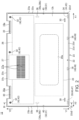
- FIG. 2 is a bottom view of the chassis 12.
- FIG. 3A is a schematic sectional view taken along line III-III in FIG. 2 .
- FIG. 3B is a sectional view illustrating a state in which the battery 28 illustrated in FIG. 3A has expanded.
- the first chassis member 22 is formed like a substantially rectangular plate.
- the second chassis member 23 is shaped like a substantially rectangular bathtub.
- the chassis members 22 and 23 can be formed of a metal material such as magnesium or aluminum, a resin material such as ABS resin or glass fiber reinforced plastic, or a carbon material such as carbon fiber reinforced plastic.
- the first chassis member 22 forms a bottom face 12b of the chassis 12.
- the first chassis member 22 has a pair of edges 22a and 22b, which extend along the Y direction and are substantially parallel to each other, and a pair of edges 22c and 22d, which extend along the X direction and are substantially parallel to each other.
- the second chassis member 23 has, on four peripheral edges thereof, vertical walls 23a to 23d that form four peripheral side faces of the chassis 12, and is open at the bottom face 12b.
- the vertical walls 23a to 23d are in close contact with the edges 22a to 22d, respectively.
- the first chassis member 22 serves as a cover member that closes the opening at the bottom face 12b of the second chassis member 23.
- the vertical wall 23c forming the side surface of the chassis 12 on the Y2 side has recessed portions 16a in the vicinity of left and right ends. The recessed portions 16a are the spaces where the hinges 16 are installed.
- a concept of the edges 22a, 22b and the edges 22c, 22d being roughly parallel to each other includes not only the case where the edges 22a to 22d are formed by perfectly straight lines and are perfectly parallel to each other, but also the case where the edges 22a to 22d have some curves or irregularities and are not perfectly parallel to each other. Therefore, the outer shape of the first chassis member 22 having the four peripheral sides formed by such edges 22a to 22d is also referred to as a substantially rectangular shape on the basis of the concept that includes a perfect square and a slightly distorted square.
- Symbol 30 in FIG. 2 denotes rubber legs fixed at appropriate positions on the bottom face 12b.
- Symbol 27a in FIG. 2 denotes intake ports for a cooling module 27, the intake ports 27a being formed of, for example, a plurality of slits opened in the bottom face 12b.
- the first chassis member 22 is detachably connected to the second chassis member 23 by using fastening parts 32, a first engagement part 34, a second engagement part 35, third engagement parts 36, attraction parts 38, and auxiliary engagement parts 40.
- each of the fastening parts 32 is composed of a screw 42 and a screw hole 43 into which the screw 42 is screwed.
- the fastening parts 32 are provided at, for example, three locations along the longitudinal direction (the X direction) of the edge 22c of the first chassis member 22.
- the fastening parts 32 fasten one end portion (on the X1 side) in the longitudinal direction of the edge 22c, the other end portion (on the X2 side) thereof, and a middle portion between these both end portions to the second chassis member 23.
- the placement and the number of the fastening parts 32 to be installed can be changed as appropriate.
- Each of the screws 42 is, for example, inserted in a Z1 direction into a boss 42a, which protrudes in the Z1 direction from an inner surface 22e of the first chassis member 22.
- Each of the screw holes 43 is formed, for example, in the inner circumferential surface of a boss 43a protruding in a Z2 direction from an inner surface 23e of the second chassis member 23. This enables the fastening parts 32 to firmly fix the edge 22c of the first chassis member 22 to the second chassis member 23.
- the first engagement part 34 is composed of an engagement piece (a first engagement piece) 44 and a receiving part (a first receiving part) 45.
- the first engagement part 34 is a hook-shaped latch engagement part that connects the edge 22d of the first chassis member 22 to the second chassis member 23.
- the first engagement part 34 is provided on the inner surface 22e of an end portion 22d1 at one end (on the X1 side) in the longitudinal direction of the edge 22d. In other words, the first engagement part 34 is positioned in the vicinity of the corner between the end portion on the X1 side and the end portion on the Y1 side of the first chassis member 22.
- FIG. 4 is an enlarged perspective view of the engagement piece 44 and a peripheral area thereof.
- FIG. 5 is an enlarged perspective view of the receiving part 45 and a peripheral area thereof.
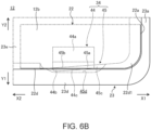
- FIG. 6A is a bottom view schematically illustrating a state immediately before the engagement piece 44 is engaged with the receiving part 45.
- FIG. 6B is a bottom view illustrating a state in which the engagement piece 44 illustrated in FIG. 6A has been engaged with the receiving part 45.
- FIG. 7 is an explanatory diagram schematically illustrating the first to the third engagement parts 34 to 36 that have been engaged.
- FIG. 7 is a schematic diagram of the chassis 12 observed from the bottom face 12b, with the first chassis member 22 other than the engagement pieces 44, 46, and 48 not being illustrated.
- the engagement piece 44 is a hook-shaped part which is provided on the inner surface 22e of the end portion 22d1 at the one end (on the X1 side) of the edge 22d and protrudes facing outward (on the Y1 side) relative to the edge 22d.
- the engagement piece 44 has a protruding piece 44a, a hook portion 44b, and a slope surface 44c.
- the protruding piece 44a is a plate piece protruding in the Z1 direction from the inner surface 22e of the first chassis member 22.
- the hook portion 44b bends from the tip of the protruding piece 44a and protrudes in the Y1 direction.
- the slope surface 44c has a configuration in which the tip surface (the end surface on the Y1 side) of the hook portion 44b is partly cut.
- the slope surface 44c is a vertical surface along the Z direction, and also gradually inclines in the X2 direction from the Y2 side to the Y1 side. This means that, in a plan view of the chassis 12, the slope surface 44c gradually inclines from the edge 22c side toward the edge 22d in the X2 direction (the first direction) extending from the end portion 22d1 at the one end of the edge 22d to an end portion 22d2 at the other end thereof.
- the hook portion 44b has such a slope surface 44c at the tip thereof. This makes it easy for the engagement piece 44 to be released from the engagement with the receiving part 45 when horizontally moving in the diagonal direction (X2/Y2 direction) between the X2 direction and the Y2 direction.
- the receiving part 45 is a part which is formed on the inner wall surface of the vertical wall 23d of the second chassis member 23 corresponding to the edge 22d, and with/from which the hook-shaped engagement piece 44 engages/disengages.
- the receiving part 45 has a receiving surface 45a and a slope surface 45b.
- the vertical wall 23d has a plate piece 45c formed to protrude in the Y2 direction from the inner wall surface.
- the receiving surface 45a is the front surface of the plate piece 45c on the Z1 side.
- the receiving surface 45a functions as a locking surface that locks, in the Z direction, the surface of the hook portion 44b of the engagement piece 44 on the Z2 side.
- the receiving part 45 in the present embodiment has a recessed portion 45d formed in the inner wall surface of the vertical wall 23d so as to be recessed on the Y1 side, thereby causing the plate piece 45c and the receiving surface 45a to protrude from the inner wall surface.
- the receiving part 45 may alternatively be formed to have the plate piece 45c protrude from the inner wall surface of the vertical wall 23d without providing the recessed portion 45d.
- the slope surface 45b has a configuration in which the tip surface (the end surface on the Y2 side) of the receiving part 45 (the plate piece 45c) is partly cut.
- the slope surface 45b is a vertical surface along the Z direction, and also gradually inclines in the X2 direction from the Y2 side to the Y1 side. This means that, when the direction of each part of the first chassis member 22 is used as the reference in the plan view of the chassis 12, the slope surface 45b gradually inclines from the edge 22c to the edge 22d in the X2 direction (the first direction) extending from the end portion 22d1 at the one end of the edge 22d to the end portion 22d2 at the other end thereof.
- the receiving part 45 has such a slope surface 45b at the tip thereof. This makes it easy for the receiving surface 45a to be easily released from the engagement with the hook portion 44b when the engagement piece 44 horizontally moves in the X2/Y2 direction.
- the second engagement part 35 is composed of the engagement piece (the second engagement piece) 46 and a receiving part (a second receiving part) 47.
- the second engagement part 35 is a hook-shaped latch engagement part that connects the edge 22d of the first chassis member 22 to the second chassis member 23.
- the second engagement part 35 is provided on the inner surface 22e of the end portion 22d2 at the other end (on the X2 side) in the longitudinal direction of the edge 22d. In other words, the second engagement part 35 is positioned in the vicinity of the corner between the end portion on the X2 side and the end portion on the Y1 side of the first chassis member 22.
- the second engagement part 35 of the present embodiment has a symmetrical shape with respect to a surface (YZ plane) orthogonal to the longitudinal direction of the edge 22d (refer to FIG. 2 and FIG. 7 ). Therefore, for each component of the engagement piece 46 and the receiving part 47, the same symbols as those of the components of the engagement piece 44 and the receiving part 45 that constitute the first engagement part 34 described above will be used, and the detailed descriptions thereof will be omitted.
- the engagement piece 46 also has the protruding piece 44a, the hook portion 44b, and the slope surface 44c.
- the slope surface 44c of the engagement piece 46 is a vertical surface along the Z direction, and gradually inclines from the Y2 side to the Y1 side in the X1 direction.
- the slope surface 44c of the engagement piece 46 gradually inclines from the edge 22d side to the edge 22c side in the X2 direction (the first direction) extending from the end portion 22d1 at the one end of the edge 22d to the end portion 22d2 at the other end thereof.
- the receiving part 47 has the receiving surface 45a and the slope surface 45b.
- the slope surface 45b of the receiving part 47 is a vertical surface along the Z direction, and gradually inclines from the Y2 side to the Y1 side in the X1 direction. More specifically, when the direction of each part of the first chassis member 22 is used as the reference in the plan view of the chassis 12, the slope surface 45b of the receiving part 47 gradually inclines from the edge 22d side to the edge 22c side in the X2 direction (the first direction) extending from the end portion 22d1 at the one end of the edge 22d to the end portion 22d2 at the other end thereof.
- the second engagement part 35 also has the slope surfaces 44c and 45b at the tips of the engagement piece 46 and the receiving part 47. This makes it easy for the second engagement part 35 to be easily released from the engagement with the receiving part 47 when the engagement piece 46 horizontally moves in the diagonal direction (X1/Y2 direction) between the X1 direction and the Y2 direction in a plan view.
- the third engagement part 36 is composed of the engagement piece (the third engagement piece) 48 and a receiving part (a third receiving part) 49.
- the third engagement part 36 is a hook-shaped latch engagement part that connects the edge 22d of the first chassis member 22 to the second chassis member 23.
- the third engagement part 36 is provided on the inner surface 22e between the end portions 22d1 and 22d2 in the longitudinal direction of the edge 22d.
- the third engagement part 36 in the present embodiment is provided in a pair side by side along the edge 22d.
- One or three or more third engagement parts 36 may be provided.
- the engagement piece 48 has a configuration in which the engagement piece 44 illustrated in FIG. 4 is not provided with the slope surface 44c. More specifically, the engagement piece 48 has a protruding piece 44a and a hook portion 44b similar to those of the engagement piece 44. However, the hook portion 44b of the engagement piece 48 does not have the tip surface thereof cut. Therefore, the end surface of the engagement piece 48 on the Y1 side is provided with a plane 48a which is a vertical surface along the Z direction and which extends along the longitudinal direction (the X direction) of the edge 22d (refer to FIG. 7 ).
- the receiving part 49 has a configuration in which the receiving part 45 illustrated in FIG. 5 is not provided with the slope surface 45b. More specifically, the receiving part 49 has the receiving surface 45a and the plate piece 45c similar to those of the receiving part 45. However, the plate piece 45c of the receiving part 49 does not have the tip surface thereof cut. Therefore, the end surface of the receiving part 49 on the Y2 side is provided with a plane 49a which is a vertical surface along the Z direction and which extends along the longitudinal direction (the X direction) of the edge 22d and the vertical wall 23d (refer to FIG. 7 ).
- each of the attraction parts 38 is composed of a first attraction piece 38a and a second attraction piece 38b, which can attract each other.
- the attraction parts 38 fix the left and right edges 22a and 22b of the first chassis member 22 to the second chassis member 23 by magnetic force.
- One of the attraction pieces 38a and 38b can be composed of a magnet, and the other can be composed of a magnet or a magnetic material, such as steel, capable of being attracted by the magnet.
- the attraction pieces 38a and 38b of the present embodiment are both magnets.
- the first attraction pieces 38a are fixed to the inner surface 22e at the middle in the longitudinal direction (the Y direction) of the left and right edges 22a and 22b of the first chassis member 22.
- the second attraction pieces 38b are fixed to the inner surface 23e of the second chassis member 23 at positions overlapping the first attraction pieces 38a in the Z direction.
- the attraction parts 38 are thus provided at the middles of the edges 22a and 22b, where the fastening parts 32 and the engagement parts 34 to 36 are not provided, i.e., in the vicinity of the centers in the Y direction, to suppress the occurrence of rattling and a gap between the chassis members 22 and 23. If, for example, the first chassis member 22 has sufficient rigidity, the attraction parts 38 may be omitted.
- each of the auxiliary engagement parts 40 is composed of an elastic engagement piece 50 and a receiving part 51.
- the auxiliary engagement parts 40 are hook-shaped latch engagement parts that connect the left and right edges 22a and 22b of the first chassis member 22 to the second chassis member 23.
- the auxiliary engagement parts 40 are provided on the inner surface 22e at the middles in the longitudinal direction (the Y direction) of the edges 22a and 22b, and are located adjacently to the attraction parts 38.
- the elastic engagement pieces 50 have hook portions that protrude facing outward relative to the edges 22a and 22b from the tips of the protruding pieces projecting in the Z1 direction from the inner surface 22e.
- the elastic engagement piece 50 of the edge 22a has the hook portion protruding in the X1 direction.
- the elastic engagement piece 50 of the edge 22b has the hook portion protruding in the X2 direction.
- the receiving parts 51 are parts which are formed on the inner wall surfaces of the vertical walls 23a and 23b of the second chassis member 23 corresponding to the edges 22a and 22b, and with/from which the hook portions of the elastic engagement pieces 50 engage/disengage.
- the elastic engagement pieces 50 are hook-shaped parts that are considerably smaller than the engagement pieces 44, 46, and 48 described above.
- the protruding pieces of the elastic engagement pieces 50 can be elastically deformed in the X direction. This enables the elastic engagement pieces 50 to be easily engaged with or disengaged from the receiving parts 51 along the Z direction.
- the auxiliary engagement parts 40 are provided at the middles of the edges 22a and 22b to suppress the occurrence of rattling and a gap between the chassis members 22 and 23. If, for example, the first chassis member 22 has sufficient rigidity, the auxiliary engagement parts 40 may be omitted.
- the battery 28 composed of, for example, a lithium polymer battery, may, although rare, develop a so-called swell phenomenon in which the volume thereof expands by 400% to 500% or more during use due to manufacturing defects or the like (refer to FIG. 3B ).
- FIG. 2 and FIG. 7 schematically illustrate an expansion part 28a of the battery 28 by surrounding with the chain line.
- the battery 28 having incurred such failure has to be replaced.
- the battery 28, when expanding presses the first chassis member 22 from the inside, leading to a problem of damage to the first chassis member 22. Therefore, the electronic apparatus 10 is provided with the above-described engagement parts 34 and 35, in particular, thus making it possible to suppress damage to the first chassis member 22 when the battery 28 expands, and to smoothly remove the battery 28 from the second chassis member 23 to replace the battery 28.
- the expansion part 28a pushes the inner surface 22e of the first chassis member 22 upward in the Z2 direction, as illustrated in FIG. 3B (refer to arrow A in FIG. 3B ).
- the battery 28 is positioned closer to the Y1 side in the chassis 12 (refer also to FIG. 2 ). Therefore, the expansion part 28a pushes the inner surface 22e at a position in the vicinity of the center of the first chassis member 22 in the X direction and closer to the edge 22d on the Y1 side rather than the edge 22c on the Y2 side.
- first chassis member 22 This causes the first chassis member 22 to be elastically deformed to expand into a dome shape or a tent shape, with a portion thereof overlapping the expansion part 28a in the Z direction so as to become a roof top, as indicated by the four arrows in FIG. 7 .
- the edge 22c moves in the Y2 direction
- the end portion 22d1 and the surroundings thereof move in the X2 direction
- the end portion 22d2 and the surroundings thereof also move to the X1 side.
- the engagement piece 44 moves in the diagonal direction (X2/Y2 direction).
- the engagement piece 46 moves in the diagonal direction (the X1/Y2 direction).
- the engagement pieces 48 move substantially in the linear direction (the Y2 direction).
- the expansion rate of the battery 28 exceeds a set value, e.g., 100% to 150%
- the engagement state at each of the engagement parts 34 to 36 is released as illustrated by the engagement pieces 44, 46, and 48 drawn in FIG. 3B and FIG. 7 .
- the engagement between the engagement pieces 44, 46, and 48 and the receiving parts 45, 47, and 49 is released, thus releasing the edge 22d (refer to arrow B in FIG. 3B ).
- the edge 22d is separated from the second chassis member 23 and lifted to the Z2 side (refer to arrow C in FIG. 3B ).
- the fixation of the attraction pieces 38a and 38b which have been fixed merely by magnetic force, is also released. Further, in the auxiliary engagement part 40, the elastic engagement piece 50 is drawn by the expansion part 28a toward the center of the first chassis member 22 in the X direction thereby to be released from the engagement with the receiving part 51.
- the fastening parts 32 are fixed by the screws 42, so that the edge 22c still remains connected to the second chassis member 23.
- the first chassis member 22 is in an open state in which the edge 22d in the vicinity of the battery 28 and a part of the left and right edges 22a, 22b on the Y1 side is detached from the second chassis member 23 and lifted to the Z2 side.
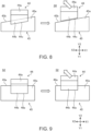
- FIG. 8 presents explanatory diagrams illustrating a change in the state of engagement with the receiving part 45 when the engagement piece 44 of the first engagement part 34 moves in a diagonal direction (X2/Y2 direction).
- FIG. 9 presents explanatory diagrams illustrating a change in the state of engagement with the receiving part 45 when an engagement piece 44 of an engagement part 52 according to the comparative example of the first engagement part 34 illustrated in FIG. 8 moves in the diagonal direction (the X2/Y2 direction).
- the engagement part 52 illustrated in FIG. 9 has a configuration in which the slope surfaces 44c and 45b of the first engagement part 34 of the example illustrated in FIG. 8 have been replaced by planes 48a and 49a similar to those of the third engagement part 36.
- the engagement piece 44 moves in the diagonal direction (the X2/Y2 direction) as the battery 28 expands, the engagement between the hook portion 44b and the receiving surface 45a is easily released. This is because the amount of engagement (the locking distance) between the hook portion 44b and the receiving surface 45a in a direction along the direction of the relative movement (the X2/Y2 direction) of the engagement piece 44 and the receiving part 45 is small due to the presence of the slope surfaces 44c and 45b.
- the hook portion 44b easily disengages from the receiving surface 45a at a shortest distance in design.
- the engagement piece 46 smoothly detaches from the receiving part 47 due to the same effect when the battery 28 expands (refer also to FIG. 7 ).
- the hook portion 44b of the engagement piece 44 that has a smaller movement distance in the Y2 direction than that of the third engagement part 36 located in the vicinity of the center of the edge 22d cannot easily detach from the receiving surface 45a.
- the first engagement part 34 of the example illustrated in FIG. 8 can detach from the receiving part 45 more smoothly when the battery 28 expands, causing the engagement piece 44 to be pulled in the diagonal direction.
- the battery 28 is placed at the position closer to the edge 22d than to the edge 22c in the chassis 12.
- the end surfaces of the engagement piece 44 provided on the end portion 22d1 at the one end of the edge (the second edge) 22d of the first chassis member 22, and the receiving part 45, which engages with and disengages from the engagement piece 44, are provided with the slope surfaces (the first slope surfaces) 44c and 45b, which gradually incline from the edge 22c side to the edge 22d side toward the end portion 22d2 at the other end.
- the end surfaces of the engagement piece 46 provided at the end portion 22d2 at the other end of the edge 22d of the first chassis member 22, and the receiving part 47, which engages with and disengages from the engagement piece 46, are provided with the slope surfaces (the second slope surfaces) 44c and 45b, which gradually incline from the edge 22d side to the edge 22c side to the end portion 22d2 side from the end portion 22d1 side.
- the edge 22c is fixed by the screws 42 of the fastening parts 32.
- the fastening parts 32 continue to support the first chassis member 22 after the chassis 12 opens at the edge 22d as described above, making it possible to prevent accidental falling or the like of the first chassis member 22 with resultant improved handleability.
- the engagement piece 44 is placed at the position beyond the end portion (side surface) of the battery 28 on the X1 side with respect to the longitudinal direction of the edge 22d, and is positioned not overlapping with the battery 28 in the Y direction (refer to FIG. 2 and FIG. 7 ).
- the engagement piece 46 is placed at the position beyond the end portion (side surface) of the battery 28 on the X2 side with respect to the longitudinal direction of the edge 22d, and is positioned not overlapping with the battery 28 in the Y direction. Consequently, when drawn by the first chassis member 22 lifted when the battery 28 expands, the engagement pieces 44 and 46 tend to have a larger movement amount in the X direction than a movement amount in the Y2 direction.
- the slope surfaces 44c and 45b provided in the engagement parts 34 and 35 of the present embodiment ensure smooth release of the engagement even when such a movement amount in the X direction is larger.
- each of the engagement parts 34 and 35 have the slope surfaces 44c and 45b, so that the engagement with each other is easily released when moving in the diagonal direction described above, whereas there is a sufficient amount of engagement (locking distance) in the Y direction when the chassis members 22 and 23 are in a normal connected state. Therefore, the engagement parts 34 and 35 are suppressed from accidental disengagement when, for example, the chassis 12 is subjected to an impact from falling or the like.
- the third engagement parts 36 located between the end portions 22d1 and 22d2 of the edge 22d are placed at the positions not beyond the end portions (the side surfaces) of the battery 28 on the X1 and X2 sides with respect to the longitudinal direction of the edge 22d, and are positioned overlapping the battery 28 in the Y direction (refer to FIG. 2 and FIG. 7 ). Therefore, when drawn by the first chassis member 22 lifted when the battery 28 expands, the engagement pieces 48 of the third engagement parts 36 hardly move in the X direction, but move exclusively in the Y2 direction.
- the third engagement parts 36 are configured to have the planes 48a and 49a along an XZ direction in place of the slope surfaces 44c and 45b so as to ensure smooth disengagement when the battery 28 expands.
- the third engagement parts 36 of course also have sufficient engagement amounts (locking distances) in the Y direction, thus suppressing accidental disengagement when the chassis 12 is subjected to an impact from falling or the like.
Landscapes
- Engineering & Computer Science (AREA)
- Computer Hardware Design (AREA)
- Theoretical Computer Science (AREA)
- General Engineering & Computer Science (AREA)
- Human Computer Interaction (AREA)
- General Physics & Mathematics (AREA)
- Physics & Mathematics (AREA)
- Power Engineering (AREA)
- General Chemical & Material Sciences (AREA)
- Electrochemistry (AREA)
- Chemical Kinetics & Catalysis (AREA)
- Chemical & Material Sciences (AREA)
- Manufacturing & Machinery (AREA)
- Life Sciences & Earth Sciences (AREA)
- Biophysics (AREA)
- Signal Processing (AREA)
- Casings For Electric Apparatus (AREA)
- Battery Mounting, Suspending (AREA)
Abstract
Description
- The present invention relates to an electronic apparatus having a battery housed in a chassis.
- An electronic apparatus such as a laptop PC, a tablet PC, or the like usually includes a chassis configured to have a flat box shape by overlapping and connecting two chassis members, and a battery housed in the chassis (refer to, for example,
Japanese Patent No. 6212322 - Currently, a lithium-ion battery, which permits both reduced thinness and larger capacity, a lithium polymer battery, which permits further reduced thickness by wrapping a cell in a thin film package, or the like is used as the above-mentioned battery. Although rare, these batteries may expand in volume by 400% to 500% or more during use due to manufacturing defects or the like. A battery that has incurred such a failure has to be replaced, but there is a concern that the battery may plastically deform or cause damage such as a crack to a chassis member when expanding. This would make it necessary not only to replace the battery but also to replace the chassis, resulting in an increase in maintenance cost and effort.
- The present invention has been made in view of the problem with the prior art described above, and an object of the present invention is to provide an electronic apparatus that can suppress damage to a chassis member even if a battery failure occurs.
- An electronic apparatus according to an aspect of the present invention includes: a chassis having a first chassis member which has a first edge and a second edge that are substantially parallel to each other and which is formed in a substantially rectangular plate shape, and a second chassis member to which the first chassis member is detachably connected; a battery housed in the chassis; a plurality of screws which are provided along the first edge of the first chassis member and which fasten the first edge to the second chassis member; a first engagement piece which is provided on one end portion in a longitudinal direction of the second edge of the first chassis member and which protrudes outward relative to the second edge; a second engagement piece which is provided on the other end portion in the longitudinal direction of the second edge of the first chassis member and which protrudes facing outward relative to the second edge; and a first receiving part which is provided on the second chassis member and with/from which the first engagement piece engages/disengages, and a second receiving part which is provided on the second chassis member and with/from which the second engagement piece engages/disengages, wherein the battery is placed at a position closer to the second edge than to the first edge in the chassis, an end surface of the first engagement piece and an end surface of the first receiving part each has a first slope surface that gradually inclines from the first edge side toward the second edge side in a first direction extending from the one end portion to the other end portion, and an end surface of the second engagement piece and an end surface of the second receiving part each has a second slope surface that gradually inclines from the second edge side toward the first edge side in the first direction.
- According to the above-described aspect of the present invention, damage to a chassis member can be suppressed even if a battery failure occurs.
-
-
FIG. 1 is a plan view of an electronic apparatus according to an embodiment. -
FIG. 2 is a bottom view of a chassis. -
FIG. 3A is a schematic sectional view taken along line III-III inFIG. 2 . -
FIG. 3B is a sectional view illustrating a state in which a battery illustrated inFIG. 3A has expanded. -
FIG. 4 is an enlarged perspective view of an engagement piece and a peripheral area thereof. -
FIG. 5 is an enlarged perspective view of a receiving part and a peripheral area thereof. -
FIG. 6A is a bottom view schematically illustrating a state immediately before an engagement piece is engaged with a receiving part. -
FIG. 6B is a bottom view illustrating a state in which the engagement piece illustrated inFIG. 6A has been engaged with the receiving part. -
FIG. 7 is an explanatory diagram schematically illustrating a first to a third engagement parts that have been engaged. -
FIG. 8 presents explanatory diagrams illustrating a change in the state of engagement with a receiving part when the engagement piece of the first engagement part moves in a diagonal direction. -
FIG. 9 presents explanatory diagrams illustrating a change in the state of engagement with a receiving part when an engagement piece of an engagement part according to a comparative example of the first engagement part illustrated inFIG. 8 moves in a diagonal direction. - The following will describe in detail a preferred embodiment of an electronic apparatus according to the present invention with reference to the accompanying drawings.
-
FIG. 1 is a plan view of anelectronic apparatus 10 according to an embodiment. Although theelectronic apparatus 10, which is a laptop PC, is illustrated in the present embodiment, the electronic apparatus to which the present invention can be applied may be other than a laptop PC, such as a tablet PC, a smartphone, or a portable game machine. As illustrated inFIG. 1 , theelectronic apparatus 10 has a configuration in which achassis 12 and acover body 14 are connected to each other byhinges 16 so as to be relatively rotatable.FIG. 1 illustrates a state in which thecover body 14 is opened from the chassis 12 (ready mode). - The
cover body 14 is formed like a flat box. Adisplay 18 is mounted on the front of thecover body 14. Thedisplay 18 is, for example, an organic EL display or a liquid crystal display. Thecover body 14 is connected to the rear edge of thechassis 12 by thehinges 16.FIG. 1 illustrates a configuration in which thecover body 14 is connected to thechassis 12 by a pair of left andright hinges 16. Thehinges 16 may have a lengthy configuration extending in an X direction, such as a so-called one-bar hinge. - Hereinafter, the
chassis 12 will be described by referring the left and right width directions as X1 and X2 directions, the front and rear depth directions as Y1 and Y2 directions, and the up and down thickness directions as Z1 and Z2 directions as seen from a user who operates akeyboard 20 while looking at thedisplay 18 in the ready mode illustrated inFIG. 1 . The X1 and X2 directions may be collectively referred to as the X direction, and the Y1 and Y2 directions and the Z1 and Z2 directions may also be similarly referred to as the Y direction and Z direction, respectively. - The
chassis 12 has a structure in which afirst chassis member 22 and asecond chassis member 23 are connected. Thechassis 12 is shaped like a flat box. Thekeyboard 20 is fixed to thesecond chassis member 23, facing afront surface 12a of thechassis 12. On thefront surface 12a of thechassis 12, atouch pad 24 is provided in front of thekeyboard 20. Housed inside thechassis 12 are electronic components such as amotherboard 26 having a CPU, memories, and the like mounted thereon, and acooling module 27 for cooling the CPU and the like. - Further, a
battery 28 serving as a power source of theelectronic apparatus 10 is also housed inside thechassis 12. Thebattery 28 is, for example, a lithium-ion battery or a lithium polymer battery. In the present embodiment, a lithium polymer battery is used. Thebattery 28 has, for example, a substantially rectangular plate shape, as a whole, that is long in the X direction and short in the Y direction. Inside thechassis 12, thebattery 28 is placed at a position closer to the Y1 side from the center in the Y direction. Therefore, thebattery 28 extends in the X direction at a position close to anedge 22d and avertical wall 23d of thechassis 12. Themotherboard 26 is placed alongside thebattery 28 on the Y2 side and extends in the X direction. - A description will now be given of a specific configuration example of the
chassis 12. -
FIG. 2 is a bottom view of thechassis 12.FIG. 3A is a schematic sectional view taken along line III-III inFIG. 2 .FIG. 3B is a sectional view illustrating a state in which thebattery 28 illustrated inFIG. 3A has expanded. As illustrated inFIG. 1 to FIG. 3A , thefirst chassis member 22 is formed like a substantially rectangular plate. Thesecond chassis member 23 is shaped like a substantially rectangular bathtub. Thechassis members - The
first chassis member 22 forms abottom face 12b of thechassis 12. Thefirst chassis member 22 has a pair ofedges edges second chassis member 23 has, on four peripheral edges thereof,vertical walls 23a to 23d that form four peripheral side faces of thechassis 12, and is open at thebottom face 12b. Thevertical walls 23a to 23d are in close contact with theedges 22a to 22d, respectively. Thefirst chassis member 22 serves as a cover member that closes the opening at thebottom face 12b of thesecond chassis member 23. Thevertical wall 23c forming the side surface of thechassis 12 on the Y2 side has recessedportions 16a in the vicinity of left and right ends. The recessedportions 16a are the spaces where thehinges 16 are installed. - A concept of the
edges edges edges 22a to 22d are formed by perfectly straight lines and are perfectly parallel to each other, but also the case where theedges 22a to 22d have some curves or irregularities and are not perfectly parallel to each other. Therefore, the outer shape of thefirst chassis member 22 having the four peripheral sides formed bysuch edges 22a to 22d is also referred to as a substantially rectangular shape on the basis of the concept that includes a perfect square and a slightly distorted square. -
Symbol 30 inFIG. 2 denotes rubber legs fixed at appropriate positions on thebottom face 12b.Symbol 27a inFIG. 2 denotes intake ports for acooling module 27, theintake ports 27a being formed of, for example, a plurality of slits opened in thebottom face 12b. - As illustrated in
FIG. 2 , thefirst chassis member 22 is detachably connected to thesecond chassis member 23 by usingfastening parts 32, afirst engagement part 34, asecond engagement part 35,third engagement parts 36,attraction parts 38, andauxiliary engagement parts 40. - As illustrated in
FIG. 2 andFIG. 3A , each of thefastening parts 32 is composed of ascrew 42 and ascrew hole 43 into which thescrew 42 is screwed. Thefastening parts 32 are provided at, for example, three locations along the longitudinal direction (the X direction) of theedge 22c of thefirst chassis member 22. Thefastening parts 32 fasten one end portion (on the X1 side) in the longitudinal direction of theedge 22c, the other end portion (on the X2 side) thereof, and a middle portion between these both end portions to thesecond chassis member 23. The placement and the number of thefastening parts 32 to be installed can be changed as appropriate. - Each of the
screws 42 is, for example, inserted in a Z1 direction into aboss 42a, which protrudes in the Z1 direction from aninner surface 22e of thefirst chassis member 22. Each of the screw holes 43 is formed, for example, in the inner circumferential surface of aboss 43a protruding in a Z2 direction from aninner surface 23e of thesecond chassis member 23. This enables thefastening parts 32 to firmly fix theedge 22c of thefirst chassis member 22 to thesecond chassis member 23. - As illustrated in
FIG. 2 andFIG. 3A , thefirst engagement part 34 is composed of an engagement piece (a first engagement piece) 44 and a receiving part (a first receiving part) 45. Thefirst engagement part 34 is a hook-shaped latch engagement part that connects theedge 22d of thefirst chassis member 22 to thesecond chassis member 23. Thefirst engagement part 34 is provided on theinner surface 22e of an end portion 22d1 at one end (on the X1 side) in the longitudinal direction of theedge 22d. In other words, thefirst engagement part 34 is positioned in the vicinity of the corner between the end portion on the X1 side and the end portion on the Y1 side of thefirst chassis member 22. -
FIG. 4 is an enlarged perspective view of theengagement piece 44 and a peripheral area thereof.FIG. 5 is an enlarged perspective view of the receivingpart 45 and a peripheral area thereof.FIG. 6A is a bottom view schematically illustrating a state immediately before theengagement piece 44 is engaged with the receivingpart 45.FIG. 6B is a bottom view illustrating a state in which theengagement piece 44 illustrated inFIG. 6A has been engaged with the receivingpart 45.FIG. 7 is an explanatory diagram schematically illustrating the first to thethird engagement parts 34 to 36 that have been engaged.FIG. 7 is a schematic diagram of thechassis 12 observed from thebottom face 12b, with thefirst chassis member 22 other than theengagement pieces - As illustrated in
FIG. 4 ,FIG. 6A , andFIG. 7 , theengagement piece 44 is a hook-shaped part which is provided on theinner surface 22e of the end portion 22d1 at the one end (on the X1 side) of theedge 22d and protrudes facing outward (on the Y1 side) relative to theedge 22d. Theengagement piece 44 has aprotruding piece 44a, ahook portion 44b, and aslope surface 44c. - The protruding
piece 44a is a plate piece protruding in the Z1 direction from theinner surface 22e of thefirst chassis member 22. Thehook portion 44b bends from the tip of the protrudingpiece 44a and protrudes in the Y1 direction. - As clearly illustrated by the dot pattern in
FIG. 4 , theslope surface 44c has a configuration in which the tip surface (the end surface on the Y1 side) of thehook portion 44b is partly cut. Theslope surface 44c is a vertical surface along the Z direction, and also gradually inclines in the X2 direction from the Y2 side to the Y1 side. This means that, in a plan view of thechassis 12, theslope surface 44c gradually inclines from theedge 22c side toward theedge 22d in the X2 direction (the first direction) extending from the end portion 22d1 at the one end of theedge 22d to an end portion 22d2 at the other end thereof. Thehook portion 44b has such aslope surface 44c at the tip thereof. This makes it easy for theengagement piece 44 to be released from the engagement with the receivingpart 45 when horizontally moving in the diagonal direction (X2/Y2 direction) between the X2 direction and the Y2 direction. - As illustrated in
FIG. 5 ,FIG. 6A , andFIG. 7 , the receivingpart 45 is a part which is formed on the inner wall surface of thevertical wall 23d of thesecond chassis member 23 corresponding to theedge 22d, and with/from which the hook-shapedengagement piece 44 engages/disengages. The receivingpart 45 has a receivingsurface 45a and aslope surface 45b. - The
vertical wall 23d has aplate piece 45c formed to protrude in the Y2 direction from the inner wall surface. The receivingsurface 45a is the front surface of theplate piece 45c on the Z1 side. The receivingsurface 45a functions as a locking surface that locks, in the Z direction, the surface of thehook portion 44b of theengagement piece 44 on the Z2 side. The receivingpart 45 in the present embodiment has a recessedportion 45d formed in the inner wall surface of thevertical wall 23d so as to be recessed on the Y1 side, thereby causing theplate piece 45c and the receivingsurface 45a to protrude from the inner wall surface. The receivingpart 45 may alternatively be formed to have theplate piece 45c protrude from the inner wall surface of thevertical wall 23d without providing the recessedportion 45d. - As clearly illustrated by the dot pattern in
FIG. 5 , theslope surface 45b has a configuration in which the tip surface (the end surface on the Y2 side) of the receiving part 45 (theplate piece 45c) is partly cut. Theslope surface 45b is a vertical surface along the Z direction, and also gradually inclines in the X2 direction from the Y2 side to the Y1 side. This means that, when the direction of each part of thefirst chassis member 22 is used as the reference in the plan view of thechassis 12, theslope surface 45b gradually inclines from theedge 22c to theedge 22d in the X2 direction (the first direction) extending from the end portion 22d1 at the one end of theedge 22d to the end portion 22d2 at the other end thereof. The receivingpart 45 has such aslope surface 45b at the tip thereof. This makes it easy for the receivingsurface 45a to be easily released from the engagement with thehook portion 44b when theengagement piece 44 horizontally moves in the X2/Y2 direction. - As illustrated in
FIG. 2 andFIG. 3A , thesecond engagement part 35 is composed of the engagement piece (the second engagement piece) 46 and a receiving part (a second receiving part) 47. Thesecond engagement part 35 is a hook-shaped latch engagement part that connects theedge 22d of thefirst chassis member 22 to thesecond chassis member 23. Thesecond engagement part 35 is provided on theinner surface 22e of the end portion 22d2 at the other end (on the X2 side) in the longitudinal direction of theedge 22d. In other words, thesecond engagement part 35 is positioned in the vicinity of the corner between the end portion on the X2 side and the end portion on the Y1 side of thefirst chassis member 22. - The
second engagement part 35 of the present embodiment has a symmetrical shape with respect to a surface (YZ plane) orthogonal to the longitudinal direction of theedge 22d (refer toFIG. 2 andFIG. 7 ). Therefore, for each component of theengagement piece 46 and the receivingpart 47, the same symbols as those of the components of theengagement piece 44 and the receivingpart 45 that constitute thefirst engagement part 34 described above will be used, and the detailed descriptions thereof will be omitted. - The
engagement piece 46 also has the protrudingpiece 44a, thehook portion 44b, and theslope surface 44c. Theslope surface 44c of theengagement piece 46 is a vertical surface along the Z direction, and gradually inclines from the Y2 side to the Y1 side in the X1 direction. In other words, in the plan view of thechassis 12, theslope surface 44c of theengagement piece 46 gradually inclines from theedge 22d side to theedge 22c side in the X2 direction (the first direction) extending from the end portion 22d1 at the one end of theedge 22d to the end portion 22d2 at the other end thereof. Similarly, the receivingpart 47 has the receivingsurface 45a and theslope surface 45b. Theslope surface 45b of the receivingpart 47 is a vertical surface along the Z direction, and gradually inclines from the Y2 side to the Y1 side in the X1 direction. More specifically, when the direction of each part of thefirst chassis member 22 is used as the reference in the plan view of thechassis 12, theslope surface 45b of the receivingpart 47 gradually inclines from theedge 22d side to theedge 22c side in the X2 direction (the first direction) extending from the end portion 22d1 at the one end of theedge 22d to the end portion 22d2 at the other end thereof. - Thus, the
second engagement part 35 also has the slope surfaces 44c and 45b at the tips of theengagement piece 46 and the receivingpart 47. This makes it easy for thesecond engagement part 35 to be easily released from the engagement with the receivingpart 47 when theengagement piece 46 horizontally moves in the diagonal direction (X1/Y2 direction) between the X1 direction and the Y2 direction in a plan view. - As illustrated in
FIG. 2 andFIG. 3A , thethird engagement part 36 is composed of the engagement piece (the third engagement piece) 48 and a receiving part (a third receiving part) 49. Thethird engagement part 36 is a hook-shaped latch engagement part that connects theedge 22d of thefirst chassis member 22 to thesecond chassis member 23. Thethird engagement part 36 is provided on theinner surface 22e between the end portions 22d1 and 22d2 in the longitudinal direction of theedge 22d. Thethird engagement part 36 in the present embodiment is provided in a pair side by side along theedge 22d. One or three or morethird engagement parts 36 may be provided. - The
engagement piece 48 has a configuration in which theengagement piece 44 illustrated inFIG. 4 is not provided with theslope surface 44c. More specifically, theengagement piece 48 has aprotruding piece 44a and ahook portion 44b similar to those of theengagement piece 44. However, thehook portion 44b of theengagement piece 48 does not have the tip surface thereof cut. Therefore, the end surface of theengagement piece 48 on the Y1 side is provided with aplane 48a which is a vertical surface along the Z direction and which extends along the longitudinal direction (the X direction) of theedge 22d (refer toFIG. 7 ). - The receiving
part 49 has a configuration in which the receivingpart 45 illustrated inFIG. 5 is not provided with theslope surface 45b. More specifically, the receivingpart 49 has the receivingsurface 45a and theplate piece 45c similar to those of the receivingpart 45. However, theplate piece 45c of the receivingpart 49 does not have the tip surface thereof cut. Therefore, the end surface of the receivingpart 49 on the Y2 side is provided with aplane 49a which is a vertical surface along the Z direction and which extends along the longitudinal direction (the X direction) of theedge 22d and thevertical wall 23d (refer toFIG. 7 ). - As illustrated in
FIG. 2 andFIG. 3A , each of theattraction parts 38 is composed of afirst attraction piece 38a and asecond attraction piece 38b, which can attract each other. Theattraction parts 38 fix the left andright edges first chassis member 22 to thesecond chassis member 23 by magnetic force. One of theattraction pieces attraction pieces - The
first attraction pieces 38a are fixed to theinner surface 22e at the middle in the longitudinal direction (the Y direction) of the left andright edges first chassis member 22. Thesecond attraction pieces 38b are fixed to theinner surface 23e of thesecond chassis member 23 at positions overlapping thefirst attraction pieces 38a in the Z direction. Theattraction parts 38 are thus provided at the middles of theedges fastening parts 32 and theengagement parts 34 to 36 are not provided, i.e., in the vicinity of the centers in the Y direction, to suppress the occurrence of rattling and a gap between thechassis members first chassis member 22 has sufficient rigidity, theattraction parts 38 may be omitted. - As illustrated in
FIG. 2 andFIG. 3A , each of theauxiliary engagement parts 40 is composed of anelastic engagement piece 50 and a receivingpart 51. Theauxiliary engagement parts 40 are hook-shaped latch engagement parts that connect the left andright edges first chassis member 22 to thesecond chassis member 23. Theauxiliary engagement parts 40 are provided on theinner surface 22e at the middles in the longitudinal direction (the Y direction) of theedges attraction parts 38. - The
elastic engagement pieces 50 have hook portions that protrude facing outward relative to theedges inner surface 22e. Theelastic engagement piece 50 of theedge 22a has the hook portion protruding in the X1 direction. Theelastic engagement piece 50 of theedge 22b has the hook portion protruding in the X2 direction. The receivingparts 51 are parts which are formed on the inner wall surfaces of thevertical walls second chassis member 23 corresponding to theedges elastic engagement pieces 50 engage/disengage. Theelastic engagement pieces 50 are hook-shaped parts that are considerably smaller than theengagement pieces elastic engagement pieces 50 can be elastically deformed in the X direction. This enables theelastic engagement pieces 50 to be easily engaged with or disengaged from the receivingparts 51 along the Z direction. - As with the
attraction parts 38, theauxiliary engagement parts 40 are provided at the middles of theedges chassis members first chassis member 22 has sufficient rigidity, theauxiliary engagement parts 40 may be omitted. - Meanwhile, in the
electronic apparatus 10 of the present embodiment, thebattery 28 composed of, for example, a lithium polymer battery, may, although rare, develop a so-called swell phenomenon in which the volume thereof expands by 400% to 500% or more during use due to manufacturing defects or the like (refer toFIG. 3B ).FIG. 2 andFIG. 7 schematically illustrate anexpansion part 28a of thebattery 28 by surrounding with the chain line. Thebattery 28 having incurred such failure has to be replaced. However, thebattery 28, when expanding, presses thefirst chassis member 22 from the inside, leading to a problem of damage to thefirst chassis member 22. Therefore, theelectronic apparatus 10 is provided with the above-describedengagement parts first chassis member 22 when thebattery 28 expands, and to smoothly remove thebattery 28 from thesecond chassis member 23 to replace thebattery 28. - A description will now be given of the operation and working effect of the
chassis 12 when thebattery 28 expands. - As illustrated in
FIG. 2 andFIG. 3A , in thechassis 12, when thechassis members screws 42 are tightened into the screw holes 43 in thefastening parts 32, theattraction pieces attraction parts 38, and theelastic engagement pieces 50 engage the receivingparts 51 in theauxiliary engagement parts 40. Further, as illustrated by theengagement pieces FIG. 2 ,FIG. 3A ,FIG. 6B , andFIG. 7 , theengagement pieces engagement parts 34 to 36 engage the receivingparts first chassis member 22 is firmly connected to thesecond chassis member 23 without rattling. - In this state, if the
battery 28 expands due to a failure or the like, theexpansion part 28a pushes theinner surface 22e of thefirst chassis member 22 upward in the Z2 direction, as illustrated inFIG. 3B (refer to arrow A inFIG. 3B ). Thebattery 28 is positioned closer to the Y1 side in the chassis 12 (refer also toFIG. 2 ). Therefore, theexpansion part 28a pushes theinner surface 22e at a position in the vicinity of the center of thefirst chassis member 22 in the X direction and closer to theedge 22d on the Y1 side rather than theedge 22c on the Y2 side. This causes thefirst chassis member 22 to be elastically deformed to expand into a dome shape or a tent shape, with a portion thereof overlapping theexpansion part 28a in the Z direction so as to become a roof top, as indicated by the four arrows inFIG. 7 . As a result, in thefirst chassis member 22, theedge 22c moves in the Y2 direction, the end portion 22d1 and the surroundings thereof move in the X2 direction, and the end portion 22d2 and the surroundings thereof also move to the X1 side. - Consequently, in the
first engagement part 34 in the vicinity of the end portion 22d1, theengagement piece 44 moves in the diagonal direction (X2/Y2 direction). In thesecond engagement part 35 in the vicinity of the end portion 22d2, theengagement piece 46 moves in the diagonal direction (the X1/Y2 direction). On the other hand, in thethird engagement parts 36 located between the end portions 22d1 and 22d2, theengagement pieces 48 move substantially in the linear direction (the Y2 direction). - Further, when, for example, the expansion rate of the
battery 28 exceeds a set value, e.g., 100% to 150%, the engagement state at each of theengagement parts 34 to 36 is released as illustrated by theengagement pieces FIG. 3B andFIG. 7 . In other words, the engagement between theengagement pieces parts edge 22d (refer to arrow B inFIG. 3B ). As a result, in thefirst chassis member 22, theedge 22d is separated from thesecond chassis member 23 and lifted to the Z2 side (refer to arrow C inFIG. 3B ). At that time, the fixation of theattraction pieces auxiliary engagement part 40, theelastic engagement piece 50 is drawn by theexpansion part 28a toward the center of thefirst chassis member 22 in the X direction thereby to be released from the engagement with the receivingpart 51. - Meanwhile, the
fastening parts 32 are fixed by thescrews 42, so that theedge 22c still remains connected to thesecond chassis member 23. As a result, thefirst chassis member 22 is in an open state in which theedge 22d in the vicinity of thebattery 28 and a part of the left andright edges second chassis member 23 and lifted to the Z2 side. - Thus, a user can quickly recognize that the
first chassis member 22 has come off due to the expansion of thebattery 28. Therefore, a maintenance worker can completely remove thefirst chassis member 22 from thesecond chassis member 23 simply by removing thescrews 42 of thefastening parts 32, and can easily replace thebattery 28. As described above, in theelectronic apparatus 10, if thebattery 28 expands, theedge 22d and the surroundings of thefirst chassis member 22 smoothly come off from thesecond chassis member 23, thus making it possible to suppress plastic deformation of or damage to thefirst chassis member 22 due to being subjected to an excessive force from theexpansion part 28a. - Referring now to
FIG. 8 and FIG. 9 , the operation and the working effect of thefirst engagement part 34 having the slope surfaces 44c and 45b (example) will be described more specifically in comparison with aconventional engagement part 52 having a typical configuration (comparative example). The operation and the working effect of thesecond engagement part 35 are substantially the same as those of thefirst engagement part 34. -
FIG. 8 presents explanatory diagrams illustrating a change in the state of engagement with the receivingpart 45 when theengagement piece 44 of thefirst engagement part 34 moves in a diagonal direction (X2/Y2 direction).FIG. 9 presents explanatory diagrams illustrating a change in the state of engagement with the receivingpart 45 when anengagement piece 44 of anengagement part 52 according to the comparative example of thefirst engagement part 34 illustrated inFIG. 8 moves in the diagonal direction (the X2/Y2 direction). - The
engagement part 52 illustrated inFIG. 9 has a configuration in which the slope surfaces 44c and 45b of thefirst engagement part 34 of the example illustrated inFIG. 8 have been replaced byplanes third engagement part 36. - In the
first engagement part 34 illustrated inFIG. 8 , when theengagement piece 44 moves in the diagonal direction (the X2/Y2 direction) as thebattery 28 expands, the engagement between thehook portion 44b and the receivingsurface 45a is easily released. This is because the amount of engagement (the locking distance) between thehook portion 44b and the receivingsurface 45a in a direction along the direction of the relative movement (the X2/Y2 direction) of theengagement piece 44 and the receivingpart 45 is small due to the presence of the slope surfaces 44c and 45b. Consequently, in thefirst engagement part 34, although the movement distance of theengagement piece 44 in the Y2 direction is smaller than thethird engagement part 36 located in the vicinity of the center of theedge 22d, thehook portion 44b easily disengages from the receivingsurface 45a at a shortest distance in design. In thesecond engagement part 35 also, theengagement piece 46 smoothly detaches from the receivingpart 47 due to the same effect when thebattery 28 expands (refer also toFIG. 7 ). - On the other hand, in the
engagement part 52 of the comparative example illustrated inFIG. 9 , even if theengagement piece 44 moves in the diagonal direction by the same distance as the case illustrated inFIG. 8 , thehook portion 44b cannot easily detach from the receivingsurface 45a. This is because thehook portion 44b and the receivingsurface 45a having theplanes engagement piece 44 and the receivingpart 45. Consequently, in theengagement part 52, thehook portion 44b of theengagement piece 44 that has a smaller movement distance in the Y2 direction than that of thethird engagement part 36 located in the vicinity of the center of theedge 22d cannot easily detach from the receivingsurface 45a. Thus, as compared with theengagement part 52 of the comparative example illustrated inFIG. 9 , thefirst engagement part 34 of the example illustrated inFIG. 8 can detach from the receivingpart 45 more smoothly when thebattery 28 expands, causing theengagement piece 44 to be pulled in the diagonal direction. - As described above, in the
electronic apparatus 10 of the present embodiment, thebattery 28 is placed at the position closer to theedge 22d than to theedge 22c in thechassis 12. The end surfaces of theengagement piece 44 provided on the end portion 22d1 at the one end of the edge (the second edge) 22d of thefirst chassis member 22, and the receivingpart 45, which engages with and disengages from theengagement piece 44, are provided with the slope surfaces (the first slope surfaces) 44c and 45b, which gradually incline from theedge 22c side to theedge 22d side toward the end portion 22d2 at the other end. Similarly, the end surfaces of theengagement piece 46 provided at the end portion 22d2 at the other end of theedge 22d of thefirst chassis member 22, and the receivingpart 47, which engages with and disengages from theengagement piece 46, are provided with the slope surfaces (the second slope surfaces) 44c and 45b, which gradually incline from theedge 22d side to theedge 22c side to the end portion 22d2 side from the end portion 22d1 side. - Therefore, according to the
electronic apparatus 10, even if thebattery 28 expands due to a failure, pressing thefirst chassis member 22, the engagement between theengagement pieces parts edge 22d positioned in the vicinity of thebattery 28 to thesecond chassis member 23, will be smoothly released. In other words, as soon as thebattery 28 expands to a predetermined expansion level or more, the connection between thechassis members chassis 12 will open at theedge 22d. As a result, it is possible to suppress the occurrence of damage, such as cracks, to thefirst chassis member 22 due to being subjected to an excessive force from thebattery 28, which has expanded, so that maintenance cost and labor can be suppressed. Theedge 22c is fixed by thescrews 42 of thefastening parts 32. Thus, thefastening parts 32 continue to support thefirst chassis member 22 after thechassis 12 opens at theedge 22d as described above, making it possible to prevent accidental falling or the like of thefirst chassis member 22 with resultant improved handleability. - In the case of the present embodiment, the
engagement piece 44 is placed at the position beyond the end portion (side surface) of thebattery 28 on the X1 side with respect to the longitudinal direction of theedge 22d, and is positioned not overlapping with thebattery 28 in the Y direction (refer toFIG. 2 andFIG. 7 ). Similarly, theengagement piece 46 is placed at the position beyond the end portion (side surface) of thebattery 28 on the X2 side with respect to the longitudinal direction of theedge 22d, and is positioned not overlapping with thebattery 28 in the Y direction. Consequently, when drawn by thefirst chassis member 22 lifted when thebattery 28 expands, theengagement pieces engagement part 52 illustrated inFIG. 9 , if the movement amount thereof in the X direction is larger as described above, then release of the engagement becomes further difficult. In this respect, the slope surfaces 44c and 45b provided in theengagement parts - The
hook portion 44b and the receivingsurface 45a of each of theengagement parts chassis members engagement parts chassis 12 is subjected to an impact from falling or the like. - On the other hand, the
third engagement parts 36 located between the end portions 22d1 and 22d2 of theedge 22d are placed at the positions not beyond the end portions (the side surfaces) of thebattery 28 on the X1 and X2 sides with respect to the longitudinal direction of theedge 22d, and are positioned overlapping thebattery 28 in the Y direction (refer toFIG. 2 andFIG. 7 ). Therefore, when drawn by thefirst chassis member 22 lifted when thebattery 28 expands, theengagement pieces 48 of thethird engagement parts 36 hardly move in the X direction, but move exclusively in the Y2 direction. Hence, thethird engagement parts 36 are configured to have theplanes battery 28 expands. Thethird engagement parts 36 of course also have sufficient engagement amounts (locking distances) in the Y direction, thus suppressing accidental disengagement when thechassis 12 is subjected to an impact from falling or the like. - The present invention is not limited to the embodiment described above, and obviously, changes can be freely added within a scope not departing from the gist of the present invention.
-
- 10
- electronic apparatus
- 12
- chassis
- 22
- first chassis member
- 23
- second chassis member
- 28
- battery
- 32
- fastening part
- 34
- first engagement part
- 35
- second engagement part
- 36
- third engagement part
- 38
- attraction part
- 38a
- first attraction piece
- 38b
- second attraction piece
- 40
- auxiliary engagement part
- 44, 46, 48
- engagement piece
- 44c, 45b
- slope surface
- 45, 47, 49, 51
- receiving part
- 48a, 49a
- plane
Claims (5)
- An electronic apparatus comprising:a chassis having a first chassis member which has a first edge and a second edge that are substantially parallel to each other and which is formed in a substantially rectangular plate shape, and a second chassis member to which the first chassis member is detachably connected;a battery housed in the chassis;a plurality of screws which are provided along the first edge of the first chassis member and which fasten the first edge to the second chassis member;a first engagement piece which is provided on one end portion in a longitudinal direction of the second edge of the first chassis member and which protrudes facing outward relative to the second edge;a second engagement piece which is provided on the other end portion in the longitudinal direction of the second edge of the first chassis member and which protrudes facing outward relative to the second edge; anda first receiving part which is provided on the second chassis member and with/from which the first engagement piece engages/disengages, and a second receiving part which is provided on the second chassis member and with/from which the second engagement piece engages/disengages,wherein the battery is located at a position closer to the second edge than to the first edge in the chassis,an end surface of the first engagement piece and an end surface of the first receiving part each has a first slope surface that gradually inclines from the first edge side to the second edge side in a first direction extending from the one end portion to the other end portion, andan end surface of the second engagement piece and an end surface of the second receiving part each has a second slope surface that gradually inclines from the second edge side to the first edge side in the first direction.
- The electronic apparatus according to claim 1,
wherein the first slope surface and the second slope surface have a symmetrical shape with respect to a plane orthogonal to a longitudinal direction of the second edge. - The electronic apparatus according to claim 1 or 2,
wherein the first engagement piece and the second engagement piece are located at positions beyond an end of the battery with respect to the longitudinal direction of the second edge, thereby not overlapping with the battery in a direction orthogonal to the longitudinal direction. - The electronic apparatus according to claim 3, further including:a third engagement piece which is provided at a position between the one end portion and the other end portion in the longitudinal direction of the second edge of the first chassis member and which protrudes facing outward relative to the second edge; anda third receiving part which is provided on the second chassis member and with/from which the third engagement piece engages/disengages,wherein the third engagement piece is located at a position not beyond an end of the battery with respect to the longitudinal direction of the second edge, thereby overlapping the battery in a direction orthogonal to the longitudinal direction, andan end surface of the third engagement piece and an end surface of the third receiving part are planes along the longitudinal direction of the second edge.
- The electronic apparatus according to claim 1,the first chassis member further having a third edge and a fourth edge, which are substantially orthogonal to the first edge and the second edge and are substantially parallel to each other,further including:a first attraction piece provided at a middle in a longitudinal direction of each of the third edge and the fourth edge of the first chassis member; anda second attraction piece which is provided on the second chassis member and which can be attracted to the first attraction piece,wherein one of the first attraction piece and the second attraction piece is a magnet and the other is a magnet or a magnetic material.
Applications Claiming Priority (1)
| Application Number | Priority Date | Filing Date | Title |
|---|---|---|---|
| JP2023123536A JP7529860B1 (en) | 2023-07-28 | 2023-07-28 | Electronics |
Publications (1)
| Publication Number | Publication Date |
|---|---|
| EP4498206A1 true EP4498206A1 (en) | 2025-01-29 |
Family
ID=91465181
Family Applications (1)
| Application Number | Title | Priority Date | Filing Date |
|---|---|---|---|
| EP24180752.8A Pending EP4498206A1 (en) | 2023-07-28 | 2024-06-07 | Electronic apparatus |
Country Status (4)
| Country | Link |
|---|---|
| US (1) | US12578760B2 (en) |
| EP (1) | EP4498206A1 (en) |
| JP (1) | JP7529860B1 (en) |
| CN (1) | CN119440175A (en) |
Citations (4)
| Publication number | Priority date | Publication date | Assignee | Title |
|---|---|---|---|---|
| US20100026609A1 (en) * | 2007-03-08 | 2010-02-04 | Nikon Corporation | Battery accommodating device, portable device, output device, and head mount display |
| US20140160655A1 (en) * | 2012-12-10 | 2014-06-12 | Lenovo (Singapore) Pte. Ltd. | Battery cover release |
| JP6212322B2 (en) | 2013-08-02 | 2017-10-11 | ホシザキ株式会社 | Thermal insulation panel |
| US20200387199A1 (en) * | 2019-06-07 | 2020-12-10 | Lenovo (Singapore) Pte. Ltd. | Electronic apparatus |
Family Cites Families (8)
| Publication number | Priority date | Publication date | Assignee | Title |
|---|---|---|---|---|
| JP4023989B2 (en) * | 2000-08-09 | 2007-12-19 | 三菱電機株式会社 | Battery pack |
| CN101728501B (en) * | 2008-10-31 | 2012-05-23 | 鸿富锦精密工业(深圳)有限公司 | Battery case |
| TWI433525B (en) * | 2009-08-12 | 2014-04-01 | Sure Best Ltd | Dect wireless hand free communication apparatus |
| JP2015185787A (en) * | 2014-03-26 | 2015-10-22 | 京セラ株式会社 | Electronics |
| WO2016053247A1 (en) * | 2014-09-29 | 2016-04-07 | Apple Inc. | Screwless joining of an enclosure with pressure sensitive adhesive and removal via pneumatic release mechanisms |
| GB2536881A (en) * | 2015-03-25 | 2016-10-05 | Tech 21 Licensing Ltd | A case for a mobile electronic device |
| US11036264B2 (en) * | 2017-12-15 | 2021-06-15 | Hewlett-Packard Development Company, L.P. | Adjustable clearance for computing devices |
| KR102408104B1 (en) * | 2018-01-16 | 2022-06-13 | 삼성전자주식회사 | Electronic device with waterproofing structure |
-
2023
- 2023-07-28 JP JP2023123536A patent/JP7529860B1/en active Active
-
2024
- 2024-06-07 EP EP24180752.8A patent/EP4498206A1/en active Pending
- 2024-06-17 US US18/744,882 patent/US12578760B2/en active Active
- 2024-07-26 CN CN202411012074.7A patent/CN119440175A/en active Pending
Patent Citations (4)
| Publication number | Priority date | Publication date | Assignee | Title |
|---|---|---|---|---|
| US20100026609A1 (en) * | 2007-03-08 | 2010-02-04 | Nikon Corporation | Battery accommodating device, portable device, output device, and head mount display |
| US20140160655A1 (en) * | 2012-12-10 | 2014-06-12 | Lenovo (Singapore) Pte. Ltd. | Battery cover release |
| JP6212322B2 (en) | 2013-08-02 | 2017-10-11 | ホシザキ株式会社 | Thermal insulation panel |
| US20200387199A1 (en) * | 2019-06-07 | 2020-12-10 | Lenovo (Singapore) Pte. Ltd. | Electronic apparatus |
Also Published As
| Publication number | Publication date |
|---|---|
| US20250036162A1 (en) | 2025-01-30 |
| US12578760B2 (en) | 2026-03-17 |
| JP7529860B1 (en) | 2024-08-06 |
| JP2025019746A (en) | 2025-02-07 |
| CN119440175A (en) | 2025-02-14 |
Similar Documents
| Publication | Publication Date | Title |
|---|---|---|
| US8289707B2 (en) | Removable assembly and communication device employing same | |
| CN109407765B (en) | holding device | |
| US10104796B1 (en) | Data storage securing device | |
| CN201064000Y (en) | Locking structure for electronic device casing | |
| CN101470476A (en) | Buckle fixing mechanism and case of notebook computer base applying same | |
| US8345446B2 (en) | Fastening structure for portable electronic device | |
| EP4498206A1 (en) | Electronic apparatus | |
| US8520398B2 (en) | Electronic device with conductive resilient sheet | |
| US20090284915A1 (en) | Computer enclosure with detachable top cover | |
| US7934780B2 (en) | Magnetic release latch mechanism for a device | |
| US20130000969A1 (en) | Shielding plate and shielding assembly with same | |
| JP7320650B1 (en) | Tape members and electronic equipment | |
| JP5461254B2 (en) | Battery pack | |
| US20100124699A1 (en) | Battery cover latching mechanism | |
| JP2000332448A (en) | Box body of electronic equipment | |
| JP6089482B2 (en) | Case and electronic device provided with case | |
| JP7571165B2 (en) | Electronic device housing and electronic device | |
| US20130088817A1 (en) | Fixing mechanism and electronic device using the same | |
| US12306673B2 (en) | Electronic apparatus, removal screw, and cover removing method | |
| JP7277854B1 (en) | Arrangement structure of the display device in the housing | |
| US20090025434A1 (en) | Buckling assembly and casing structure using the same | |
| US20080036218A1 (en) | Liftable cover for a computer casing | |
| CN1929722B (en) | Information processing unit with detachable front and rear covers | |
| WO2012090380A1 (en) | Battery pack, secondary battery housing case, and battery pack assembling method | |
| CN201064001Y (en) | Self-locking structure for electronic device casing |
Legal Events
| Date | Code | Title | Description |
|---|---|---|---|
| PUAI | Public reference made under article 153(3) epc to a published international application that has entered the european phase |
Free format text: ORIGINAL CODE: 0009012 |
|
| STAA | Information on the status of an ep patent application or granted ep patent |
Free format text: STATUS: THE APPLICATION HAS BEEN PUBLISHED |
|
| AK | Designated contracting states |
Kind code of ref document: A1 Designated state(s): AL AT BE BG CH CY CZ DE DK EE ES FI FR GB GR HR HU IE IS IT LI LT LU LV MC ME MK MT NL NO PL PT RO RS SE SI SK SM TR |
|
| STAA | Information on the status of an ep patent application or granted ep patent |
Free format text: STATUS: REQUEST FOR EXAMINATION WAS MADE |
|
| 17P | Request for examination filed |
Effective date: 20250519 |
|
| GRAP | Despatch of communication of intention to grant a patent |
Free format text: ORIGINAL CODE: EPIDOSNIGR1 |
|
| STAA | Information on the status of an ep patent application or granted ep patent |
Free format text: STATUS: GRANT OF PATENT IS INTENDED |
|
| RIC1 | Information provided on ipc code assigned before grant |
Ipc: G06F 1/16 20060101AFI20251210BHEP Ipc: H01M 50/247 20210101ALI20251210BHEP Ipc: H04M 1/02 20060101ALI20251210BHEP |
|
| INTG | Intention to grant announced |
Effective date: 20260102 |
|
| GRAS | Grant fee paid |
Free format text: ORIGINAL CODE: EPIDOSNIGR3 |
|
| GRAA | (expected) grant |
Free format text: ORIGINAL CODE: 0009210 |
|
| STAA | Information on the status of an ep patent application or granted ep patent |
Free format text: STATUS: THE PATENT HAS BEEN GRANTED |