EP4498171A1 - Image forming apparatus - Google Patents
Image forming apparatus Download PDFInfo
- Publication number
- EP4498171A1 EP4498171A1 EP24158419.2A EP24158419A EP4498171A1 EP 4498171 A1 EP4498171 A1 EP 4498171A1 EP 24158419 A EP24158419 A EP 24158419A EP 4498171 A1 EP4498171 A1 EP 4498171A1
- Authority
- EP
- European Patent Office
- Prior art keywords
- driving unit
- image forming
- front side
- forming apparatus
- harnesses
- Prior art date
- Legal status (The legal status is an assumption and is not a legal conclusion. Google has not performed a legal analysis and makes no representation as to the accuracy of the status listed.)
- Granted
Links
Images





Classifications
-
- G—PHYSICS
- G03—PHOTOGRAPHY; CINEMATOGRAPHY; ANALOGOUS TECHNIQUES USING WAVES OTHER THAN OPTICAL WAVES; ELECTROGRAPHY; HOLOGRAPHY
- G03G—ELECTROGRAPHY; ELECTROPHOTOGRAPHY; MAGNETOGRAPHY
- G03G21/00—Arrangements not provided for by groups G03G13/00 - G03G19/00, e.g. cleaning, elimination of residual charge
- G03G21/16—Mechanical means for facilitating the maintenance of the apparatus, e.g. modular arrangements
- G03G21/1661—Mechanical means for facilitating the maintenance of the apparatus, e.g. modular arrangements means for handling parts of the apparatus in the apparatus
-
- G—PHYSICS
- G03—PHOTOGRAPHY; CINEMATOGRAPHY; ANALOGOUS TECHNIQUES USING WAVES OTHER THAN OPTICAL WAVES; ELECTROGRAPHY; HOLOGRAPHY
- G03G—ELECTROGRAPHY; ELECTROPHOTOGRAPHY; MAGNETOGRAPHY
- G03G21/00—Arrangements not provided for by groups G03G13/00 - G03G19/00, e.g. cleaning, elimination of residual charge
- G03G21/16—Mechanical means for facilitating the maintenance of the apparatus, e.g. modular arrangements
- G03G21/18—Mechanical means for facilitating the maintenance of the apparatus, e.g. modular arrangements using a processing cartridge, whereby the process cartridge comprises at least two image processing means in a single unit
- G03G21/1839—Means for handling the process cartridge in the apparatus body
- G03G21/1857—Means for handling the process cartridge in the apparatus body for transmitting mechanical drive power to the process cartridge, drive mechanisms, gears, couplings, braking mechanisms
-
- G—PHYSICS
- G03—PHOTOGRAPHY; CINEMATOGRAPHY; ANALOGOUS TECHNIQUES USING WAVES OTHER THAN OPTICAL WAVES; ELECTROGRAPHY; HOLOGRAPHY
- G03G—ELECTROGRAPHY; ELECTROPHOTOGRAPHY; MAGNETOGRAPHY
- G03G21/00—Arrangements not provided for by groups G03G13/00 - G03G19/00, e.g. cleaning, elimination of residual charge
- G03G21/16—Mechanical means for facilitating the maintenance of the apparatus, e.g. modular arrangements
- G03G21/1604—Arrangement or disposition of the entire apparatus
- G03G21/1619—Frame structures
-
- G—PHYSICS
- G03—PHOTOGRAPHY; CINEMATOGRAPHY; ANALOGOUS TECHNIQUES USING WAVES OTHER THAN OPTICAL WAVES; ELECTROGRAPHY; HOLOGRAPHY
- G03G—ELECTROGRAPHY; ELECTROPHOTOGRAPHY; MAGNETOGRAPHY
- G03G21/00—Arrangements not provided for by groups G03G13/00 - G03G19/00, e.g. cleaning, elimination of residual charge
- G03G21/16—Mechanical means for facilitating the maintenance of the apparatus, e.g. modular arrangements
- G03G21/1642—Mechanical means for facilitating the maintenance of the apparatus, e.g. modular arrangements for connecting the different parts of the apparatus
- G03G21/1647—Mechanical connection means
-
- G—PHYSICS
- G03—PHOTOGRAPHY; CINEMATOGRAPHY; ANALOGOUS TECHNIQUES USING WAVES OTHER THAN OPTICAL WAVES; ELECTROGRAPHY; HOLOGRAPHY
- G03G—ELECTROGRAPHY; ELECTROPHOTOGRAPHY; MAGNETOGRAPHY
- G03G21/00—Arrangements not provided for by groups G03G13/00 - G03G19/00, e.g. cleaning, elimination of residual charge
- G03G21/16—Mechanical means for facilitating the maintenance of the apparatus, e.g. modular arrangements
- G03G21/1642—Mechanical means for facilitating the maintenance of the apparatus, e.g. modular arrangements for connecting the different parts of the apparatus
- G03G21/1652—Electrical connection means
Definitions
- the present disclosure relates to an image forming apparatus.
- Japanese Unexamined Patent Application Publication No. 2019-211533 describes a technology with which a temporary holder assembled to a toner supply unit temporarily holds a harness connector disconnected from a control-substrate-attached connector in an attachment/removal operation of a driving unit to or from an apparatus body for maintenance or in other operations.
- This technology is designed to improve the workability of attaching or removing a control unit to or from the apparatus body.
- an image forming apparatus including a rear frame disposed on a rear side in a housing, the housing allowing access to a component on a front side in the housing; a driving unit that is attached to a front side of the rear frame to drive a toner cartridge; and a substrate assembly that is disposed on a rear side of the rear frame, and connected to the driving unit with a harness.
- a harness connected to the driving unit extends in a vertical direction at a position visually identifiable from a front side in a state where a component on a front side of the driving unit is removed.
- the harness connected to the driving unit is connected to the substrate assembly while passing over an upper end of the rear frame.
- the harness connected to the driving unit is supported by an attachable and removable clip at a position visually identifiable from the front side.
- the driving unit is attached to the rear frame with a fastening member attachable and removable from a front side.
- a direction in which the fastening member is removed is a frontward direction.
- the image forming apparatus reduces an operation of removing the substrate assembly to which the harnesses are connected to facilitate attachment or removal of the driving units compared to a structure where the driving units are accessed from the rear side for attachment or removal.
- the image forming apparatus enhances visual identification of the positions of the harnesses compared to a structure where the harnesses connected to the driving units extend in the width direction.
- the image forming apparatus enhances visual identification of the positions of the harnesses compared to a structure where the harnesses connected to the driving units extend through the rear frame.
- the image forming apparatus allows access to the clips supporting the harnesses from the front side for attachment or removal.
- the image forming apparatus allows access to fastening members that attach the driving unit to the rear frame from the front side for attachment or removal.
- the image forming apparatus facilitates attachment or removal of the fastening members compared to a structure where the fastening members are attached or removed in the vertical direction or the width direction.
- an image forming apparatus forms images with toner of yellow (Y), cyan (C), magenta (M), and black (B).
- Arrow FR indicated as appropriate in the drawings indicates the front side of the image forming apparatus
- arrow UP indicates the upper side of the image forming apparatus
- arrow RH indicates the right side of the image forming apparatus.
- an image forming apparatus 10 includes a housing 12.
- the housing 12 accommodates an image forming portion 18, a rear frame 16, a driving unit 20, a substrate assembly 30, and harnesses 40.
- the housing 12 has a rectangular box shape, and has an openable covering 12A on the front side. Opening the covering 12A allows a user to access components installed in the housing 12 from the front side of the image forming apparatus 10.
- An operation panel 14 through which the user operates the image forming apparatus 10 is located at an upper portion of the housing 12 on the front side.
- the image forming apparatus 10 outputs a recording medium on which an image is formed.
- the image forming apparatus 10 may make copies of an original document, or perform authenticating print in response to an operation of the user on the operation panel 14.
- the image forming portion 18 includes, for example, a toner cartridge (not illustrated).
- the image forming portion 18 is removable by being accessed from the front side of the image forming apparatus 10.
- the image forming portion 18 may include an image forming unit (not illustrated) including a photoconductor drum (not illustrated) and a developing device (not illustrated).
- the rear frame 16 is located on a rear side of the image forming apparatus 10.
- the rear frame 16 includes a longitudinal board 16A and a top board 16B, and has an L-shaped cross section.
- the longitudinal board 16A has a shape of a rectangular board with a board thickness in the apparatus front-rear direction. As illustrated in Fig. 1 and Fig. 4 , the longitudinal board 16A has an opening 16C that is open in the board thickness direction.
- the top board 16B has a shape of a rectangular board having a board thickness in the apparatus top-bottom direction.
- the longitudinal board 16A and the top board 16B each have multiple through-holes (not illustrated) to which clips C that support the harness 40 are fastened.
- the driving unit 20 is coupled to the image forming portion 18 on the front side of the driving unit 20 to drive the image forming portion 18.
- the driving unit 20 serves as a dispense unit that transports toner accommodated in the toner cartridge (not illustrated) to a developing device (not illustrated) of the corresponding color.
- the driving unit 20 is attached to the longitudinal board 16A of the rear frame 16 with screws S serving as example fastening members with attachment mounts 22.
- the attachment mounts 22 protrude outward from the outer edge of the driving unit 20.
- Two attachment mounts 22 protrude upward from an upper portion of the driving unit 20, and two attachment mounts 22 protrude downward from a lower portion of the driving unit 20.
- each attachment mount 22 has a rectangular box shape with the front side open.
- Each attachment mount 22 has a through-hole 22A in a surface having a board thickness in the apparatus front-rear direction.
- the through-hole 22A receives a screw S, and the driving unit 20 is thus attached to the rear frame 16.
- the direction in which the screw S is attached is a rear side direction, and a direction in which the screw S is removed is a frontward direction.
- the driving unit 20 is attached to the rear frame 16 with the screws S attachable and removable from the front side.
- Each attachment mount 22 has a rectangular box shape with the front side open, and thus receives the screw S when it falls off.
- each attachment mount 22 located at an upper portion of the driving unit 20 and having a board thickness in the apparatus front-rear direction, a boss 22B extends rearward.
- the driving unit 20 has its position fixed relative to the rear frame 16.
- the driving unit 20 includes driving portions 21 that drive the toner cartridges, and motor portions 25 connected to the driving portions 21.
- the driving portions 21 include a first driving portion 21A for driving a toner cartridge of black (B), a second driving portion 21B for driving a toner cartridge of magenta (M), a third driving portion 21C for driving a toner cartridge of cyan (C), and a fourth driving portion 21D for driving a toner cartridge of yellow (Y), which are located on the front side of the driving unit 20.
- the first driving portion 21A detects the remaining amount of toner in the toner cartridge for black (B).
- the second driving portion 21B detects the remaining amount of toner in the toner cartridge for magenta (M).
- the third driving portion 21C detects the remaining amount of toner in the toner cartridge for cyan (C).
- the fourth driving portion 21D detects the remaining amount of toner in the toner cartridge for yellow (Y).
- the motor portions 25 are located on the rear side of the driving unit 20, and includes a first motor portion 25A and a second motor portion 25B.
- the substrate assembly 30 is attached to the rear side of the rear frame 16 with the screws S.
- the substrate assembly 30 is connected to the driving unit 20 with the harnesses 40.
- the substrate assembly 30 includes a first substrate 31 and a second substrate 32 disposed above the first substrate 31.
- the first substrate 31 includes a receptacle 31A serving as a coupler to which plugs of the harnesses 40 are coupled.
- the second substrate 32 also includes a receptacle serving as a coupler to which plugs of the harnesses 40 are coupled.
- the harnesses 40 include communication harnesses 41 and power supply harnesses 42.
- the communication harnesses 41 are used for communication of information on the remaining amount of toner in each toner cartridge detected by the corresponding driving portion 21.
- the communication harnesses 41 include a first communication harness 41A, a second communication harness 41B, a third communication harness 41C, and a fourth communication harness 41D.
- the first communication harness 41A is, for example, a wire cable, and connects the first driving portion 21A and the first substrate 31 to each other.
- a plug (not illustrated) of the first communication harness 41A at a first end is connected to a receptacle 21AA in the first driving portion 21A on the apparatus right side.
- the first communication harness 41A extends to the apparatus right side along the front side surface of the driving unit 20, then to the apparatus upper side, then to the apparatus right side along the upper surface of the top board 16B, and is then drawn out to the rear side of the rear frame 16.
- the first communication harness 41A is supported by multiple clips C. The clips C are disposed at positions where the first communication harness 41A changes its direction.
- the second communication harness 41B is, for example, a wire cable, and connects the second driving portion 21B and the first substrate 31 to each other.
- a plug (not illustrated) of the second communication harness 41B at a first end is connected to a receptacle 21BA in the second driving portion 21B on the apparatus right side.
- the second communication harness 41B extends to the apparatus right side along the front side surface of the driving unit 20, then to the apparatus upper side, then to the apparatus right side along the upper surface of the top board 16B, and is then drawn out to the rear side of the rear frame 16.
- the second communication harness 41B is supported by multiple clips C. The clips C are disposed at positions where the second communication harness 41B changes its direction.
- the third communication harness 41C is, for example, a wire cable, and connects the third driving portion 21C and the first substrate 31 to each other.
- a plug (not illustrated) of the third communication harness 41C at a first end is connected to a receptacle 21CA in the third driving portion 21C on the apparatus right side.
- the third communication harness 41C extends to the apparatus right side along the front side surface of the driving unit 20, and then to the apparatus upper side, and is then drawn out to the rear side of the rear frame 16 along the upper surface of the top board 16B.
- the third communication harness 41C is supported by multiple clips C. The clips C are disposed at positions where the third communication harness 41C changes its direction.
- the fourth communication harness 41D is, for example, a wire cable, and connects the fourth driving portion 21D and the first substrate 31 to each other.
- a plug (not illustrated) of the fourth communication harness 41D at a first end is connected to a receptacle 21DA in the fourth driving portion 21D on the apparatus right side.
- the fourth communication harness 41D extends to the apparatus right side along the front side surface of the driving unit 20, and then to the apparatus upper side, and is then drawn out to the rear side of the rear frame 16 along the upper surface of the top board 16B.
- the fourth communication harness 41D is supported by multiple clips C. The clips C are disposed at positions where the fourth communication harness 41D changes its direction.
- the power supply harnesses 42 are used to supply power to the motor portion 25.
- the power supply harnesses 42 include a first power supply harness 42A and a second power supply harness 42B.
- the first power supply harness 42A is, for example, a wire cable, and connects the first motor portion 25A and the first substrate 31 to each other.
- a plug (not illustrated) of the first power supply harness 42A at a first end is connected to a receptacle 25AA in the first motor portion 25A on the apparatus left side.
- the first power supply harness 42A extends to below the first motor portion 25A along the rear side surface of the driving unit 20, and then to the apparatus upper side, and is then drawn to the front side of the longitudinal board 16A through an opening 20A in the driving unit 20.
- the first power supply harness 42A then extends to the apparatus upper side along the front side surface of the longitudinal board 16A, and then to the apparatus right side along the upper surface of the top board 16B, and is then drawn out to the rear side of the rear frame 16.
- the first power supply harness 42A is supported by multiple clips C.
- the second power supply harness 42B is, for example, a wire cable, and connects the second motor portion 25B and the first substrate 31 to each other.
- a plug (not illustrated) of the second power supply harness 42B at a first end is connected to a receptacle 25BA in the second motor portion 25B on the apparatus left side.
- the second power supply harness 42B is bent to an apparatus lower side along the rear side surface of the driving unit 20, then extends to the apparatus upper side, and is then drawn to the front side of the longitudinal board 16A through the opening 20A in the driving unit 20.
- the second power supply harness 42B then extends to the apparatus upper side along the front side surface of the longitudinal board 16A, and then to the apparatus right side along the upper surface of the top board 16B, and is then drawn out to the rear side of the rear frame 16.
- the second power supply harness 42B is supported by multiple clips C.
- the first communication harness 41A, the second communication harness 41B, the third communication harness 41C, the fourth communication harness 41D, the first power supply harness 42A, and the second power supply harness 42B are bundled at a middle portion of the upper surface of the top board 16B in an apparatus width direction, and are drawn to the rear side of the rear frame 16.
- the communication harnesses 41 and the power supply harnesses 42 are connected to the substrate assembly 30 while passing over the upper end of the rear frame 16.
- the communication harnesses 41 and the power supply harnesses 42 extend in the vertical direction at positions visually identifiable from the front side.
- the communication harnesses 41 are supported by the attachable and removable clips C at positions visually identifiable from the front side.
- a preferable example of the position visually identifiable from the front side may be the apparatus upper side of the rear frame 16.
- the communication harnesses 41 are connected to the driving portions 21 in the same direction.
- the power supply harnesses 42 are connected to the driving portions 21 in the same direction.
- the direction in which the communication harnesses 41 are connected to the driving portions 21 is opposite to the direction in which the power supply harnesses 42 are connected to the driving portions 21.
- the user opens the covering 12A of the housing 12.
- the user then accesses the inside of the housing 12 from the front side to draw the image forming portion 18 to the front side to remove.
- the user then accesses the inside of the housing 12 from the front side to unfasten the screws S attached to the driving unit 20.
- the user then draws the driving unit 20 to the front side. At this time, the user may remove the clips C attached to the harness 40. The user then removes the communication harnesses 41 and the power supply harnesses 42 connected to the driving unit 20 from the driving unit 20.
- the user then draws the driving unit 20 to the front side to remove the driving unit 20 from the image forming apparatus 10.
- the communication harnesses 41 and the power supply harnesses 42 are in the state of hanging from the upper end of the rear frame 16. In this state, when the user accesses the inside of the housing 12 from the front side, a plug 411 at the end of each communication harness 41 and a plug 421 at the end of each power supply harness 42 are visually identifiable from the front side.
- the substrate assembly 30 is to be removed.
- the harnesses 40 connected to the substrate assembly 30 are also to be removed, and the operation may be complex.
- the image forming apparatus 10 includes the rear frame 16 disposed on the rear side in the housing 12 that allows access to components on the front side, the driving unit 20 that is attached to a front side of the rear frame 16 to drive the toner cartridges, and the substrate assembly 30 that is disposed on a rear side of the rear frame 16 and connected to the driving unit 20 with the harnesses 40 (refer to Fig. 1 ).
- the driving unit 20 that drives the toner cartridges is attached to the front side of the rear frame 16, and thus, accessed from the front side for attachment or removal. Compared to the structure where the driving unit 20 is accessed from the rear side for attachment or removal, this structure reduces an operation of removing the substrate assembly 30 to which the harnesses 40 are connected, and thus facilitates attachment or removal of the driving unit 20.
- the harnesses 40 connected to the driving unit 20 extend in the vertical direction at the positions visually identifiable from the front side in the state where the components on the front side of the driving unit 20 are removed (refer to Fig. 2 ).
- the harnesses 40 connected to the driving unit 20 extend in the vertical direction at the positions visually identifiable from the front side in the state where the components on the front side of the driving unit 20 are removed, and thus the positions of the harnesses 40 are more easily visually identifiable than in a structure where the harnesses 40 connected to the driving unit 20 extend in the width direction.
- the harnesses 40 connected to the driving unit 20 are connected to the substrate assembly 30 while passing over the upper end of the rear frame 16 (refer to Fig. 6 ).
- the harnesses 40 connected to the driving unit 20 are connected to the substrate assembly 30 while passing over the upper end of the rear frame 16, and thus the positions of the harnesses 40 are visually identified from the front side when an operator accesses the driving unit 20 from the front side to remove.
- the positions of the harnesses 40 are more easily visually identifiable than in a structure where the harnesses 40 connected to the driving unit 20 extend through the rear frame 16.
- the harnesses 40 are hanging down from the upper end of the rear frame 16.
- the positions of the harnesses 40 are more easily visually identifiable than in the case where the harnesses 40 are hanging down from a middle portion of the rear frame 16.
- the harnesses 40 connected to the driving unit 20 are supported by the attachable and removable clips C at positions visually identifiable from the front side in the state where the components on the front side of the driving unit 20 are removed (refer to Fig. 2 ).
- the harnesses 40 connected to the driving unit 20 are supported by the attachable and removable clips C at positions visually identifiable from the front side in the state where the components on the front side of the driving unit 20 are removed, and thus the clips C supporting the harnesses 40 are accessible from the front side for attachment or removal.
- the driving unit 20 is attached to the rear frame 16 with the attachable and removable screws S from the front side (refer to Fig. 8 ).
- the driving unit 20 is attached to the rear frame 16 with the attachable and removable screws S from the front side, and thus the screws S that attach the driving unit 20 to the rear frame 16 are accessible from the front side for attachment or removal.
- the direction in which the screws S are removed is a frontward direction (refer to Fig. 8 ).
- the direction in which the screws S are removed is a frontward direction, and thus a workspace for a tool to attach or remove the screws S is provided on the front side of the driving unit 20.
- the screws S are more easily attached and removed than in a structure where the screws S are attached or removed in the vertical direction or the width direction.
- the present disclosure is not limited to the above exemplary embodiment, and may be modified, changed, or improved in various manners within the scope of the technical idea of the present disclosure.
- the harnesses 40 include wire harnesses serving as the communication harnesses 41 and wire harnesses serving as the power supply harnesses 42.
- the harnesses are not limited to this aspect, and may be, for example, flat cables.
- the driving unit 20 is attached to the rear frame 16 with the screws S.
- the driving unit may be attached to the rear frame with other fastening members such as bolts.
- the covering 12A in the housing 12 is opened to allow the user to access the components installed in the housing 12 from the front side of the image forming apparatus 10.
- the housing may be removed to allow the user to access the components installed in the housing from the front side of the image forming apparatus 10.
- the image forming apparatus 10 outputs recording media on which images are formed.
- the image forming apparatus may include a printer, a copying machine, a fax machine, a printing device, or a multifunction device including a combination of two or more of these.
- the image forming apparatus may have an authenticating print function of allowing print through authentication.
- the image forming apparatus reduces an operation of removing the substrate assembly to which the harnesses are connected to facilitate attachment or removal of the driving units compared to a structure where the driving units are accessed from the rear side for attachment or removal.
- the image forming apparatus enhances visual identification of the positions of the harnesses compared to a structure where the harnesses connected to the driving units extend in the width direction.
- the image forming apparatus enhances visual identification of the positions of the harnesses compared to a structure where the harnesses connected to the driving units extend through the rear frame.
- the image forming apparatus according to ((4))) allows access to the clips supporting the harnesses from the front side for attachment or removal.
- the image forming apparatus according to ((5))) allows access to fastening members that attach the driving unit to the rear frame from the front side for attachment or removal.
- the image forming apparatus according to ((6))) facilitates attachment or removal of the fastening members compared to a structure where the fastening members are attached or removed in the vertical direction or the width direction.
Landscapes
- Physics & Mathematics (AREA)
- General Physics & Mathematics (AREA)
- Engineering & Computer Science (AREA)
- Computer Vision & Pattern Recognition (AREA)
- Electrophotography Configuration And Component (AREA)
- Insertion, Bundling And Securing Of Wires For Electric Apparatuses (AREA)
Abstract
Description
- The present disclosure relates to an image forming apparatus.
-
Japanese Unexamined Patent Application Publication No. 2019-211533 - Accordingly, it is an object of the present disclosure to provide facilitation of attachment or removal of a driving unit compared to a structure where a driving unit is fixed to a rear portion of a rear frame.
- According to a first aspect of the present disclosure, there is provided an image forming apparatus including a rear frame disposed on a rear side in a housing, the housing allowing access to a component on a front side in the housing; a driving unit that is attached to a front side of the rear frame to drive a toner cartridge; and a substrate assembly that is disposed on a rear side of the rear frame, and connected to the driving unit with a harness.
- In an image forming apparatus according to a second aspect dependent on the image forming apparatus according to the first aspect, a harness connected to the driving unit extends in a vertical direction at a position visually identifiable from a front side in a state where a component on a front side of the driving unit is removed.
- In an image forming apparatus according to a third aspect dependent on the image forming apparatus according to the first or second aspect, the harness connected to the driving unit is connected to the substrate assembly while passing over an upper end of the rear frame.
- In an image forming apparatus according to a fourth aspect dependent on the image forming apparatus according to the second aspect, the harness connected to the driving unit is supported by an attachable and removable clip at a position visually identifiable from the front side.
- In an image forming apparatus according to a fifth aspect dependent on the image forming apparatus according to any one of the first to fourth aspect, the driving unit is attached to the rear frame with a fastening member attachable and removable from a front side.
- In an image forming apparatus according to a sixth aspect dependent on the image forming apparatus according to the fifth aspect, a direction in which the fastening member is removed is a frontward direction.
- The image forming apparatus according to the first aspect reduces an operation of removing the substrate assembly to which the harnesses are connected to facilitate attachment or removal of the driving units compared to a structure where the driving units are accessed from the rear side for attachment or removal.
- The image forming apparatus according to the second aspect enhances visual identification of the positions of the harnesses compared to a structure where the harnesses connected to the driving units extend in the width direction.
- The image forming apparatus according to the third aspect enhances visual identification of the positions of the harnesses compared to a structure where the harnesses connected to the driving units extend through the rear frame.
- The image forming apparatus according to the fourth aspect allows access to the clips supporting the harnesses from the front side for attachment or removal.
- The image forming apparatus according to the fifth aspect allows access to fastening members that attach the driving unit to the rear frame from the front side for attachment or removal.
- The image forming apparatus according to the sixth aspect facilitates attachment or removal of the fastening members compared to a structure where the fastening members are attached or removed in the vertical direction or the width direction.
- Exemplary embodiments of the present disclosure will be described in detail based on the following figures, wherein:
-
Fig. 1 is a schematic cross-sectional view of a structure of an image forming apparatus according to an exemplary embodiment; -
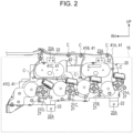
Fig. 2 is a front view of a driving unit according to an exemplary embodiment; -
Fig. 3 is a perspective view of a driving unit according to an exemplary embodiment to which harnesses are attached, viewed from the front; -
Fig. 4 is a rear view of a driving unit according to an exemplary embodiment; -
Fig. 5 is a perspective view of a driving unit according to an exemplary embodiment to which harnesses are attached, viewed from the rear; -
Fig. 6 is a perspective view of harnesses according to an exemplary embodiment in the state where the harnesses are passing over a rear frame; -
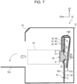
Fig. 7 is a diagram illustrating a procedure of removing a driving unit according to an exemplary embodiment; -
Fig. 8 is a diagram illustrating a procedure of removing a driving unit according to an exemplary embodiment; -
Fig. 9 is a diagram illustrating a procedure of removing a driving unit according to an exemplary embodiment; and -
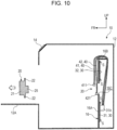
Fig. 10 is a diagram illustrating a procedure of removing a driving unit according to an exemplary embodiment. - An image forming apparatus according to an exemplary embodiment is described below with reference to the drawings. In an exemplary embodiment, for example, an image forming apparatus forms images with toner of yellow (Y), cyan (C), magenta (M), and black (B). Arrow FR indicated as appropriate in the drawings indicates the front side of the image forming apparatus, arrow UP indicates the upper side of the image forming apparatus, and arrow RH indicates the right side of the image forming apparatus.
- As illustrated in
Fig. 1 , animage forming apparatus 10 includes ahousing 12. Thehousing 12 accommodates animage forming portion 18, arear frame 16, adriving unit 20, a substrate assembly 30, and harnesses 40. - The
housing 12 has a rectangular box shape, and has anopenable covering 12A on the front side. Opening the covering 12A allows a user to access components installed in thehousing 12 from the front side of theimage forming apparatus 10. - An
operation panel 14 through which the user operates theimage forming apparatus 10 is located at an upper portion of thehousing 12 on the front side. When the user operates theoperation panel 14, theimage forming apparatus 10 outputs a recording medium on which an image is formed. Instead, theimage forming apparatus 10 may make copies of an original document, or perform authenticating print in response to an operation of the user on theoperation panel 14. - The
image forming portion 18 includes, for example, a toner cartridge (not illustrated). Theimage forming portion 18 is removable by being accessed from the front side of theimage forming apparatus 10. Theimage forming portion 18 may include an image forming unit (not illustrated) including a photoconductor drum (not illustrated) and a developing device (not illustrated). - As illustrated in
Fig. 1 , therear frame 16 is located on a rear side of theimage forming apparatus 10. Therear frame 16 includes alongitudinal board 16A and atop board 16B, and has an L-shaped cross section. - The
longitudinal board 16A has a shape of a rectangular board with a board thickness in the apparatus front-rear direction. As illustrated inFig. 1 andFig. 4 , thelongitudinal board 16A has an opening 16C that is open in the board thickness direction. - As illustrated in
Fig. 1 andFig. 3 , thetop board 16B has a shape of a rectangular board having a board thickness in the apparatus top-bottom direction. Thelongitudinal board 16A and thetop board 16B each have multiple through-holes (not illustrated) to which clips C that support the harness 40 are fastened. - As illustrated in
Fig. 1 , thedriving unit 20 is coupled to theimage forming portion 18 on the front side of thedriving unit 20 to drive theimage forming portion 18. When driving, for example, a toner cartridge, thedriving unit 20 serves as a dispense unit that transports toner accommodated in the toner cartridge (not illustrated) to a developing device (not illustrated) of the corresponding color. - As illustrated in
Fig. 1 andFig. 2 , thedriving unit 20 is attached to thelongitudinal board 16A of therear frame 16 with screws S serving as example fastening members withattachment mounts 22. - The attachment mounts 22 protrude outward from the outer edge of the
driving unit 20. Twoattachment mounts 22 protrude upward from an upper portion of thedriving unit 20, and twoattachment mounts 22 protrude downward from a lower portion of thedriving unit 20. - As illustrated in
Fig. 3 , eachattachment mount 22 has a rectangular box shape with the front side open. Eachattachment mount 22 has a through-hole 22A in a surface having a board thickness in the apparatus front-rear direction. The through-hole 22A receives a screw S, and thedriving unit 20 is thus attached to therear frame 16. The direction in which the screw S is attached is a rear side direction, and a direction in which the screw S is removed is a frontward direction. The drivingunit 20 is attached to therear frame 16 with the screws S attachable and removable from the front side. Each attachment mount 22 has a rectangular box shape with the front side open, and thus receives the screw S when it falls off. - On the surface of each attachment mount 22 located at an upper portion of the driving
unit 20 and having a board thickness in the apparatus front-rear direction, aboss 22B extends rearward. When theboss 22B is received in a through-hole in therear frame 16, the drivingunit 20 has its position fixed relative to therear frame 16. - As illustrated in
Fig. 1 , the drivingunit 20 includes drivingportions 21 that drive the toner cartridges, andmotor portions 25 connected to the drivingportions 21. - As illustrated in
Fig. 2 , the drivingportions 21 include afirst driving portion 21A for driving a toner cartridge of black (B), asecond driving portion 21B for driving a toner cartridge of magenta (M), athird driving portion 21C for driving a toner cartridge of cyan (C), and afourth driving portion 21D for driving a toner cartridge of yellow (Y), which are located on the front side of the drivingunit 20. - The
first driving portion 21A detects the remaining amount of toner in the toner cartridge for black (B). Thesecond driving portion 21B detects the remaining amount of toner in the toner cartridge for magenta (M). Thethird driving portion 21C detects the remaining amount of toner in the toner cartridge for cyan (C). Thefourth driving portion 21D detects the remaining amount of toner in the toner cartridge for yellow (Y). - As illustrated in
Fig. 4 andFig. 5 , themotor portions 25 are located on the rear side of the drivingunit 20, and includes afirst motor portion 25A and asecond motor portion 25B. - In the state where the driving
unit 20 is attached to therear frame 16, themotor portions 25 protrude rearward from theopening 16C in therear frame 16. - As illustrated in
Fig. 1 , the substrate assembly 30 is attached to the rear side of therear frame 16 with the screws S. The substrate assembly 30 is connected to the drivingunit 20 with the harnesses 40. The substrate assembly 30 includes a first substrate 31 and a second substrate 32 disposed above the first substrate 31. - The first substrate 31 includes a
receptacle 31A serving as a coupler to which plugs of the harnesses 40 are coupled. Although not illustrated, the second substrate 32 also includes a receptacle serving as a coupler to which plugs of the harnesses 40 are coupled. - As illustrated in
Fig. 1 , the harnesses 40 include communication harnesses 41 and power supply harnesses 42. - The communication harnesses 41 are used for communication of information on the remaining amount of toner in each toner cartridge detected by the corresponding driving
portion 21. - As illustrated in
Fig. 2 , the communication harnesses 41 include afirst communication harness 41A, asecond communication harness 41B, athird communication harness 41C, and afourth communication harness 41D. - As illustrated in
Fig. 3 andFig. 6 , thefirst communication harness 41A is, for example, a wire cable, and connects thefirst driving portion 21A and the first substrate 31 to each other. A plug (not illustrated) of thefirst communication harness 41A at a first end is connected to a receptacle 21AA in thefirst driving portion 21A on the apparatus right side. Thefirst communication harness 41A extends to the apparatus right side along the front side surface of the drivingunit 20, then to the apparatus upper side, then to the apparatus right side along the upper surface of thetop board 16B, and is then drawn out to the rear side of therear frame 16. Thefirst communication harness 41A is supported by multiple clips C. The clips C are disposed at positions where thefirst communication harness 41A changes its direction. - The
second communication harness 41B is, for example, a wire cable, and connects thesecond driving portion 21B and the first substrate 31 to each other. A plug (not illustrated) of thesecond communication harness 41B at a first end is connected to a receptacle 21BA in thesecond driving portion 21B on the apparatus right side. Thesecond communication harness 41B extends to the apparatus right side along the front side surface of the drivingunit 20, then to the apparatus upper side, then to the apparatus right side along the upper surface of thetop board 16B, and is then drawn out to the rear side of therear frame 16. Thesecond communication harness 41B is supported by multiple clips C. The clips C are disposed at positions where thesecond communication harness 41B changes its direction. - The
third communication harness 41C is, for example, a wire cable, and connects thethird driving portion 21C and the first substrate 31 to each other. A plug (not illustrated) of thethird communication harness 41C at a first end is connected to a receptacle 21CA in thethird driving portion 21C on the apparatus right side. Thethird communication harness 41C extends to the apparatus right side along the front side surface of the drivingunit 20, and then to the apparatus upper side, and is then drawn out to the rear side of therear frame 16 along the upper surface of thetop board 16B. Thethird communication harness 41C is supported by multiple clips C. The clips C are disposed at positions where thethird communication harness 41C changes its direction. - The
fourth communication harness 41D is, for example, a wire cable, and connects thefourth driving portion 21D and the first substrate 31 to each other. A plug (not illustrated) of thefourth communication harness 41D at a first end is connected to a receptacle 21DA in thefourth driving portion 21D on the apparatus right side. Thefourth communication harness 41D extends to the apparatus right side along the front side surface of the drivingunit 20, and then to the apparatus upper side, and is then drawn out to the rear side of therear frame 16 along the upper surface of thetop board 16B. Thefourth communication harness 41D is supported by multiple clips C. The clips C are disposed at positions where thefourth communication harness 41D changes its direction. - The power supply harnesses 42 are used to supply power to the
motor portion 25. - As illustrated in
Fig. 4 , the power supply harnesses 42 include a firstpower supply harness 42A and a secondpower supply harness 42B. - As illustrated in
Fig. 5 , the firstpower supply harness 42A is, for example, a wire cable, and connects thefirst motor portion 25A and the first substrate 31 to each other. A plug (not illustrated) of the firstpower supply harness 42A at a first end is connected to a receptacle 25AA in thefirst motor portion 25A on the apparatus left side. The firstpower supply harness 42A extends to below thefirst motor portion 25A along the rear side surface of the drivingunit 20, and then to the apparatus upper side, and is then drawn to the front side of thelongitudinal board 16A through an opening 20A in the drivingunit 20. The firstpower supply harness 42A then extends to the apparatus upper side along the front side surface of thelongitudinal board 16A, and then to the apparatus right side along the upper surface of thetop board 16B, and is then drawn out to the rear side of therear frame 16. The firstpower supply harness 42A is supported by multiple clips C. - The second
power supply harness 42B is, for example, a wire cable, and connects thesecond motor portion 25B and the first substrate 31 to each other. A plug (not illustrated) of the secondpower supply harness 42B at a first end is connected to a receptacle 25BA in thesecond motor portion 25B on the apparatus left side. The secondpower supply harness 42B is bent to an apparatus lower side along the rear side surface of the drivingunit 20, then extends to the apparatus upper side, and is then drawn to the front side of thelongitudinal board 16A through the opening 20A in the drivingunit 20. The secondpower supply harness 42B then extends to the apparatus upper side along the front side surface of thelongitudinal board 16A, and then to the apparatus right side along the upper surface of thetop board 16B, and is then drawn out to the rear side of therear frame 16. The secondpower supply harness 42B is supported by multiple clips C. - The
first communication harness 41A, thesecond communication harness 41B, thethird communication harness 41C, thefourth communication harness 41D, the firstpower supply harness 42A, and the secondpower supply harness 42B are bundled at a middle portion of the upper surface of thetop board 16B in an apparatus width direction, and are drawn to the rear side of therear frame 16. The communication harnesses 41 and the power supply harnesses 42 are connected to the substrate assembly 30 while passing over the upper end of therear frame 16. - In the state where the
image forming portion 18 is removed, the communication harnesses 41 and the power supply harnesses 42 extend in the vertical direction at positions visually identifiable from the front side. In the state where theimage forming portion 18 is removed, the communication harnesses 41 are supported by the attachable and removable clips C at positions visually identifiable from the front side. In the state where theimage forming portion 18 is removed, a preferable example of the position visually identifiable from the front side may be the apparatus upper side of therear frame 16. - The communication harnesses 41 are connected to the driving
portions 21 in the same direction. The power supply harnesses 42 are connected to the drivingportions 21 in the same direction. The direction in which the communication harnesses 41 are connected to the drivingportions 21 is opposite to the direction in which the power supply harnesses 42 are connected to the drivingportions 21. - As illustrated in
Fig. 7 , the user opens thecovering 12A of thehousing 12. The user then accesses the inside of thehousing 12 from the front side to draw theimage forming portion 18 to the front side to remove. - As illustrated in
Fig. 8 , the user then accesses the inside of thehousing 12 from the front side to unfasten the screws S attached to the drivingunit 20. - As illustrated in
Fig. 9 , the user then draws the drivingunit 20 to the front side. At this time, the user may remove the clips C attached to the harness 40. The user then removes the communication harnesses 41 and the power supply harnesses 42 connected to the drivingunit 20 from the drivingunit 20. - As illustrated in
Fig. 10 , the user then draws the drivingunit 20 to the front side to remove the drivingunit 20 from theimage forming apparatus 10. The communication harnesses 41 and the power supply harnesses 42 are in the state of hanging from the upper end of therear frame 16. In this state, when the user accesses the inside of thehousing 12 from the front side, aplug 411 at the end of eachcommunication harness 41 and aplug 421 at the end of eachpower supply harness 42 are visually identifiable from the front side. - To access the driving
unit 20 from the rear side for attachment or removal, the substrate assembly 30 is to be removed. In this case, the harnesses 40 connected to the substrate assembly 30 are also to be removed, and the operation may be complex. - The
image forming apparatus 10 according to an exemplary embodiment includes therear frame 16 disposed on the rear side in thehousing 12 that allows access to components on the front side, the drivingunit 20 that is attached to a front side of therear frame 16 to drive the toner cartridges, and the substrate assembly 30 that is disposed on a rear side of therear frame 16 and connected to the drivingunit 20 with the harnesses 40 (refer toFig. 1 ). - The driving
unit 20 that drives the toner cartridges is attached to the front side of therear frame 16, and thus, accessed from the front side for attachment or removal. Compared to the structure where the drivingunit 20 is accessed from the rear side for attachment or removal, this structure reduces an operation of removing the substrate assembly 30 to which the harnesses 40 are connected, and thus facilitates attachment or removal of the drivingunit 20. - In the
image forming apparatus 10 according to an exemplary embodiment, the harnesses 40 connected to the drivingunit 20 extend in the vertical direction at the positions visually identifiable from the front side in the state where the components on the front side of the drivingunit 20 are removed (refer toFig. 2 ). - The harnesses 40 connected to the driving
unit 20 extend in the vertical direction at the positions visually identifiable from the front side in the state where the components on the front side of the drivingunit 20 are removed, and thus the positions of the harnesses 40 are more easily visually identifiable than in a structure where the harnesses 40 connected to the drivingunit 20 extend in the width direction. - In the
image forming apparatus 10 according to an exemplary embodiment, the harnesses 40 connected to the drivingunit 20 are connected to the substrate assembly 30 while passing over the upper end of the rear frame 16 (refer toFig. 6 ). - The harnesses 40 connected to the driving
unit 20 are connected to the substrate assembly 30 while passing over the upper end of therear frame 16, and thus the positions of the harnesses 40 are visually identified from the front side when an operator accesses the drivingunit 20 from the front side to remove. Thus, the positions of the harnesses 40 are more easily visually identifiable than in a structure where the harnesses 40 connected to the drivingunit 20 extend through therear frame 16. - When the driving
unit 20 is to be attached, the harnesses 40 are hanging down from the upper end of therear frame 16. Thus, the positions of the harnesses 40 are more easily visually identifiable than in the case where the harnesses 40 are hanging down from a middle portion of therear frame 16. - In the
image forming apparatus 10 according to an exemplary embodiment, the harnesses 40 connected to the drivingunit 20 are supported by the attachable and removable clips C at positions visually identifiable from the front side in the state where the components on the front side of the drivingunit 20 are removed (refer toFig. 2 ). - The harnesses 40 connected to the driving
unit 20 are supported by the attachable and removable clips C at positions visually identifiable from the front side in the state where the components on the front side of the drivingunit 20 are removed, and thus the clips C supporting the harnesses 40 are accessible from the front side for attachment or removal. - In the
image forming apparatus 10 according to an exemplary embodiment, the drivingunit 20 is attached to therear frame 16 with the attachable and removable screws S from the front side (refer toFig. 8 ). - The driving
unit 20 is attached to therear frame 16 with the attachable and removable screws S from the front side, and thus the screws S that attach the drivingunit 20 to therear frame 16 are accessible from the front side for attachment or removal. - In the
image forming apparatus 10 according to an exemplary embodiment, the direction in which the screws S are removed is a frontward direction (refer toFig. 8 ). - The direction in which the screws S are removed is a frontward direction, and thus a workspace for a tool to attach or remove the screws S is provided on the front side of the driving
unit 20. Thus, the screws S are more easily attached and removed than in a structure where the screws S are attached or removed in the vertical direction or the width direction. - As described above, a specific exemplary embodiment of the present disclosure is described above, the present disclosure is not limited to the above exemplary embodiment, and may be modified, changed, or improved in various manners within the scope of the technical idea of the present disclosure.
- In the exemplary embodiment, for example, the harnesses 40 include wire harnesses serving as the communication harnesses 41 and wire harnesses serving as the power supply harnesses 42. However, the harnesses are not limited to this aspect, and may be, for example, flat cables.
- In the exemplary embodiment, for example, the driving
unit 20 is attached to therear frame 16 with the screws S. However, the driving unit may be attached to the rear frame with other fastening members such as bolts. - In the exemplary embodiment, for example, the
covering 12A in thehousing 12 is opened to allow the user to access the components installed in thehousing 12 from the front side of theimage forming apparatus 10. Instead, the housing may be removed to allow the user to access the components installed in the housing from the front side of theimage forming apparatus 10. - In the exemplary embodiment, for example, the
image forming apparatus 10 outputs recording media on which images are formed. Instead, the image forming apparatus may include a printer, a copying machine, a fax machine, a printing device, or a multifunction device including a combination of two or more of these. The image forming apparatus may have an authenticating print function of allowing print through authentication. - The foregoing description of the exemplary embodiments of the present disclosure has been provided for the purposes of illustration and description. It is not intended to be exhaustive or to limit the disclosure to the precise forms disclosed. Obviously, many modifications and variations will be apparent to practitioners skilled in the art. The embodiments were chosen and described in order to best explain the principles of the disclosure and its practical applications, thereby enabling others skilled in the art to understand the disclosure for various embodiments and with the various modifications as are suited to the particular use contemplated. It is intended that the scope of the disclosure be defined by the following claims and their equivalents.
-
- (((1))) An image forming apparatus comprising:
- a rear frame disposed on a rear side in a housing, the housing allowing access to a component on a front side in the housing;
- a driving unit that is attached to a front side of the rear frame to drive a toner cartridge; and
- a substrate assembly that is disposed on a rear side of the rear frame, and connected to the driving unit with a harness.
- (((2))) The image forming apparatus according to (((1))),
wherein a harness connected to the driving unit extends in a vertical direction at a position visually identifiable from a front side in a state where a component on a front side of the driving unit is removed. - (((3))) The image forming apparatus according to (((1))) or (((2))),
wherein the harness connected to the driving unit is connected to the substrate assembly while passing over an upper end of the rear frame. - (((4))) The image forming apparatus according to (((2))),
wherein the harness connected to the driving unit is supported by an attachable and removable clip at a position visually identifiable from the front side. - (((5))) The image forming apparatus according to any one of (((1))) to (((4))),
wherein the driving unit is attached to the rear frame with a fastening member attachable and removable from a front side. - (((6))) The image forming apparatus according to (((5))),
wherein a direction in which the fastening member is removed is a frontward direction. - The image forming apparatus according to ((1))) reduces an operation of removing the substrate assembly to which the harnesses are connected to facilitate attachment or removal of the driving units compared to a structure where the driving units are accessed from the rear side for attachment or removal.
- The image forming apparatus according to ((2))) enhances visual identification of the positions of the harnesses compared to a structure where the harnesses connected to the driving units extend in the width direction.
- The image forming apparatus according to ((3))) enhances visual identification of the positions of the harnesses compared to a structure where the harnesses connected to the driving units extend through the rear frame.
- The image forming apparatus according to ((4))) allows access to the clips supporting the harnesses from the front side for attachment or removal.
- The image forming apparatus according to ((5))) allows access to fastening members that attach the driving unit to the rear frame from the front side for attachment or removal.
- The image forming apparatus according to ((6))) facilitates attachment or removal of the fastening members compared to a structure where the fastening members are attached or removed in the vertical direction or the width direction.
Claims (6)
- An image forming apparatus comprising:a rear frame disposed on a rear side in a housing, the housing allowing access to a component on a front side in the housing;a driving unit that is attached to a front side of the rear frame to drive a toner cartridge; anda substrate assembly that is disposed on a rear side of the rear frame, and connected to the driving unit with a harness.
- The image forming apparatus according to claim 1,
wherein a harness connected to the driving unit extends in a vertical direction at a position visually identifiable from a front side in a state where a component on a front side of the driving unit is removed. - The image forming apparatus according to claim 1 or 2,
wherein the harness connected to the driving unit is connected to the substrate assembly while passing over an upper end of the rear frame. - The image forming apparatus according to claim 2,
wherein the harness connected to the driving unit is supported by an attachable and removable clip at a position visually identifiable from the front side. - The image forming apparatus according to any one of claims 1 to 4,
wherein the driving unit is attached to the rear frame with a fastening member attachable and removable from a front side. - The image forming apparatus according to claim 5,
wherein a direction in which the fastening member is removed is a frontward direction.
Applications Claiming Priority (1)
| Application Number | Priority Date | Filing Date | Title |
|---|---|---|---|
| JP2023122889A JP2025018837A (en) | 2023-07-27 | 2023-07-27 | Image forming apparatus |
Publications (2)
| Publication Number | Publication Date |
|---|---|
| EP4498171A1 true EP4498171A1 (en) | 2025-01-29 |
| EP4498171B1 EP4498171B1 (en) | 2025-09-10 |
Family
ID=89984869
Family Applications (1)
| Application Number | Title | Priority Date | Filing Date |
|---|---|---|---|
| EP24158419.2A Active EP4498171B1 (en) | 2023-07-27 | 2024-02-19 | Image forming apparatus |
Country Status (4)
| Country | Link |
|---|---|
| US (1) | US12298702B2 (en) |
| EP (1) | EP4498171B1 (en) |
| JP (1) | JP2025018837A (en) |
| CN (1) | CN119376217A (en) |
Citations (4)
| Publication number | Priority date | Publication date | Assignee | Title |
|---|---|---|---|---|
| US20070230988A1 (en) * | 2006-03-29 | 2007-10-04 | Brother Kogyo Kabushiki Kaisha | Image Forming Apparatus |
| JP2018189811A (en) * | 2017-05-08 | 2018-11-29 | 株式会社リコー | Image forming apparatus and storge device |
| JP2019211533A (en) | 2018-05-31 | 2019-12-12 | 京セラドキュメントソリューションズ株式会社 | Electrical equipment |
| US20220015219A1 (en) * | 2020-07-09 | 2022-01-13 | Canon Kabushiki Kaisha | Apparatus |
Family Cites Families (1)
| Publication number | Priority date | Publication date | Assignee | Title |
|---|---|---|---|---|
| JP7703399B2 (en) * | 2021-08-27 | 2025-07-07 | キヤノン株式会社 | Developing unit |
-
2023
- 2023-07-27 JP JP2023122889A patent/JP2025018837A/en active Pending
-
2024
- 2024-02-16 US US18/443,425 patent/US12298702B2/en active Active
- 2024-02-19 CN CN202410183864.5A patent/CN119376217A/en active Pending
- 2024-02-19 EP EP24158419.2A patent/EP4498171B1/en active Active
Patent Citations (4)
| Publication number | Priority date | Publication date | Assignee | Title |
|---|---|---|---|---|
| US20070230988A1 (en) * | 2006-03-29 | 2007-10-04 | Brother Kogyo Kabushiki Kaisha | Image Forming Apparatus |
| JP2018189811A (en) * | 2017-05-08 | 2018-11-29 | 株式会社リコー | Image forming apparatus and storge device |
| JP2019211533A (en) | 2018-05-31 | 2019-12-12 | 京セラドキュメントソリューションズ株式会社 | Electrical equipment |
| US20220015219A1 (en) * | 2020-07-09 | 2022-01-13 | Canon Kabushiki Kaisha | Apparatus |
Also Published As
| Publication number | Publication date |
|---|---|
| JP2025018837A (en) | 2025-02-06 |
| US12298702B2 (en) | 2025-05-13 |
| CN119376217A (en) | 2025-01-28 |
| EP4498171B1 (en) | 2025-09-10 |
| US20250036072A1 (en) | 2025-01-30 |
Similar Documents
| Publication | Publication Date | Title |
|---|---|---|
| CN105527809B (en) | Image processing system | |
| US8112011B2 (en) | Image forming apparatus | |
| US9880512B2 (en) | Image forming apparatus including an outer cover and a subsidiary cover | |
| KR20090013854A (en) | Image Forming Device | |
| EP4498171B1 (en) | Image forming apparatus | |
| US9037031B2 (en) | Image forming apparatus including control substrate connected to electrical component through cable | |
| JP4537466B2 (en) | Image forming apparatus | |
| US10852685B2 (en) | Drum cartridge and image forming apparatus | |
| CN109212925B (en) | Image forming apparatus with a plurality of image forming units | |
| JP5156600B2 (en) | Electric wire protection structure and image forming apparatus provided with the same | |
| JP2002023437A (en) | Image forming device | |
| CN209765270U (en) | Carbon powder box | |
| US12032320B2 (en) | Image forming apparatus with particularity arranged electric boards | |
| EP3702883A1 (en) | Hard disk fixing structure | |
| US11689007B2 (en) | Image forming apparatus | |
| JP2009071823A (en) | Image forming apparatus | |
| JP5182569B2 (en) | Image forming apparatus | |
| JP2004085889A (en) | Electrical unit and image forming apparatus | |
| JP2002031924A (en) | Electrical part lock mechanism | |
| JP2009169121A (en) | Image forming apparatus | |
| JP2001334725A (en) | Image forming device | |
| JP7739913B2 (en) | printer | |
| US20090040545A1 (en) | Image forming apparatus equipped with scanner portion for reading an original and printer portion for forming an image on a sheet | |
| JPH08274478A (en) | Electric / electronic equipment | |
| JP2005214998A (en) | Image forming apparatus |
Legal Events
| Date | Code | Title | Description |
|---|---|---|---|
| PUAI | Public reference made under article 153(3) epc to a published international application that has entered the european phase |
Free format text: ORIGINAL CODE: 0009012 |
|
| STAA | Information on the status of an ep patent application or granted ep patent |
Free format text: STATUS: THE APPLICATION HAS BEEN PUBLISHED |
|
| AK | Designated contracting states |
Kind code of ref document: A1 Designated state(s): AL AT BE BG CH CY CZ DE DK EE ES FI FR GB GR HR HU IE IS IT LI LT LU LV MC ME MK MT NL NO PL PT RO RS SE SI SK SM TR |
|
| STAA | Information on the status of an ep patent application or granted ep patent |
Free format text: STATUS: REQUEST FOR EXAMINATION WAS MADE |
|
| 17P | Request for examination filed |
Effective date: 20250328 |
|
| GRAP | Despatch of communication of intention to grant a patent |
Free format text: ORIGINAL CODE: EPIDOSNIGR1 |
|
| STAA | Information on the status of an ep patent application or granted ep patent |
Free format text: STATUS: GRANT OF PATENT IS INTENDED |
|
| RIC1 | Information provided on ipc code assigned before grant |
Ipc: G03G 21/18 20060101ALI20250423BHEP Ipc: G03G 21/16 20060101AFI20250423BHEP |
|
| INTG | Intention to grant announced |
Effective date: 20250507 |
|
| GRAS | Grant fee paid |
Free format text: ORIGINAL CODE: EPIDOSNIGR3 |
|
| GRAA | (expected) grant |
Free format text: ORIGINAL CODE: 0009210 |
|
| STAA | Information on the status of an ep patent application or granted ep patent |
Free format text: STATUS: THE PATENT HAS BEEN GRANTED |
|
| AK | Designated contracting states |
Kind code of ref document: B1 Designated state(s): AL AT BE BG CH CY CZ DE DK EE ES FI FR GB GR HR HU IE IS IT LI LT LU LV MC ME MK MT NL NO PL PT RO RS SE SI SK SM TR |
|
| REG | Reference to a national code |
Ref country code: GB Ref legal event code: FG4D |
|
| REG | Reference to a national code |
Ref country code: CH Ref legal event code: EP |
|
| REG | Reference to a national code |
Ref country code: DE Ref legal event code: R096 Ref document number: 602024000612 Country of ref document: DE |
|
| REG | Reference to a national code |
Ref country code: IE Ref legal event code: FG4D |
|
| PG25 | Lapsed in a contracting state [announced via postgrant information from national office to epo] |
Ref country code: NO Free format text: LAPSE BECAUSE OF FAILURE TO SUBMIT A TRANSLATION OF THE DESCRIPTION OR TO PAY THE FEE WITHIN THE PRESCRIBED TIME-LIMIT Effective date: 20251210 |
|
| REG | Reference to a national code |
Ref country code: LT Ref legal event code: MG9D |
|
| PG25 | Lapsed in a contracting state [announced via postgrant information from national office to epo] |
Ref country code: FI Free format text: LAPSE BECAUSE OF FAILURE TO SUBMIT A TRANSLATION OF THE DESCRIPTION OR TO PAY THE FEE WITHIN THE PRESCRIBED TIME-LIMIT Effective date: 20250910 |
|
| REG | Reference to a national code |
Ref country code: NL Ref legal event code: MP Effective date: 20250910 |
|
| PG25 | Lapsed in a contracting state [announced via postgrant information from national office to epo] |
Ref country code: HR Free format text: LAPSE BECAUSE OF FAILURE TO SUBMIT A TRANSLATION OF THE DESCRIPTION OR TO PAY THE FEE WITHIN THE PRESCRIBED TIME-LIMIT Effective date: 20250910 |
|
| PGFP | Annual fee paid to national office [announced via postgrant information from national office to epo] |
Ref country code: FR Payment date: 20251231 Year of fee payment: 3 |
|
| PG25 | Lapsed in a contracting state [announced via postgrant information from national office to epo] |
Ref country code: GR Free format text: LAPSE BECAUSE OF FAILURE TO SUBMIT A TRANSLATION OF THE DESCRIPTION OR TO PAY THE FEE WITHIN THE PRESCRIBED TIME-LIMIT Effective date: 20251211 |
|
| PG25 | Lapsed in a contracting state [announced via postgrant information from national office to epo] |
Ref country code: SE Free format text: LAPSE BECAUSE OF FAILURE TO SUBMIT A TRANSLATION OF THE DESCRIPTION OR TO PAY THE FEE WITHIN THE PRESCRIBED TIME-LIMIT Effective date: 20250910 |
|
| PG25 | Lapsed in a contracting state [announced via postgrant information from national office to epo] |
Ref country code: LV Free format text: LAPSE BECAUSE OF FAILURE TO SUBMIT A TRANSLATION OF THE DESCRIPTION OR TO PAY THE FEE WITHIN THE PRESCRIBED TIME-LIMIT Effective date: 20250910 |
|
| PG25 | Lapsed in a contracting state [announced via postgrant information from national office to epo] |
Ref country code: PL Free format text: LAPSE BECAUSE OF FAILURE TO SUBMIT A TRANSLATION OF THE DESCRIPTION OR TO PAY THE FEE WITHIN THE PRESCRIBED TIME-LIMIT Effective date: 20250910 Ref country code: BG Free format text: LAPSE BECAUSE OF FAILURE TO SUBMIT A TRANSLATION OF THE DESCRIPTION OR TO PAY THE FEE WITHIN THE PRESCRIBED TIME-LIMIT Effective date: 20250910 |
|
| PG25 | Lapsed in a contracting state [announced via postgrant information from national office to epo] |
Ref country code: RS Free format text: LAPSE BECAUSE OF FAILURE TO SUBMIT A TRANSLATION OF THE DESCRIPTION OR TO PAY THE FEE WITHIN THE PRESCRIBED TIME-LIMIT Effective date: 20251210 |
|
| PG25 | Lapsed in a contracting state [announced via postgrant information from national office to epo] |
Ref country code: ES Free format text: LAPSE BECAUSE OF FAILURE TO SUBMIT A TRANSLATION OF THE DESCRIPTION OR TO PAY THE FEE WITHIN THE PRESCRIBED TIME-LIMIT Effective date: 20250910 |
|
| REG | Reference to a national code |
Ref country code: AT Ref legal event code: MK05 Ref document number: 1836507 Country of ref document: AT Kind code of ref document: T Effective date: 20250910 |
|
| PG25 | Lapsed in a contracting state [announced via postgrant information from national office to epo] |
Ref country code: NL Free format text: LAPSE BECAUSE OF FAILURE TO SUBMIT A TRANSLATION OF THE DESCRIPTION OR TO PAY THE FEE WITHIN THE PRESCRIBED TIME-LIMIT Effective date: 20250910 |
|
| P01 | Opt-out of the competence of the unified patent court (upc) registered |
Free format text: CASE NUMBER: UPC_APP_0000820_4498171/2026 Effective date: 20260109 |
|
| PG25 | Lapsed in a contracting state [announced via postgrant information from national office to epo] |
Ref country code: SM Free format text: LAPSE BECAUSE OF FAILURE TO SUBMIT A TRANSLATION OF THE DESCRIPTION OR TO PAY THE FEE WITHIN THE PRESCRIBED TIME-LIMIT Effective date: 20250910 |
|
| PGFP | Annual fee paid to national office [announced via postgrant information from national office to epo] |
Ref country code: DE Payment date: 20251230 Year of fee payment: 3 |
|
| PG25 | Lapsed in a contracting state [announced via postgrant information from national office to epo] |
Ref country code: AT Free format text: LAPSE BECAUSE OF FAILURE TO SUBMIT A TRANSLATION OF THE DESCRIPTION OR TO PAY THE FEE WITHIN THE PRESCRIBED TIME-LIMIT Effective date: 20250910 |
|
| PG25 | Lapsed in a contracting state [announced via postgrant information from national office to epo] |
Ref country code: IT Free format text: LAPSE BECAUSE OF FAILURE TO SUBMIT A TRANSLATION OF THE DESCRIPTION OR TO PAY THE FEE WITHIN THE PRESCRIBED TIME-LIMIT Effective date: 20250910 |
|
| PG25 | Lapsed in a contracting state [announced via postgrant information from national office to epo] |
Ref country code: IS Free format text: LAPSE BECAUSE OF FAILURE TO SUBMIT A TRANSLATION OF THE DESCRIPTION OR TO PAY THE FEE WITHIN THE PRESCRIBED TIME-LIMIT Effective date: 20260110 |
|
| PG25 | Lapsed in a contracting state [announced via postgrant information from national office to epo] |
Ref country code: CZ Free format text: LAPSE BECAUSE OF FAILURE TO SUBMIT A TRANSLATION OF THE DESCRIPTION OR TO PAY THE FEE WITHIN THE PRESCRIBED TIME-LIMIT Effective date: 20250910 Ref country code: PT Free format text: LAPSE BECAUSE OF FAILURE TO SUBMIT A TRANSLATION OF THE DESCRIPTION OR TO PAY THE FEE WITHIN THE PRESCRIBED TIME-LIMIT Effective date: 20260112 |
|
| PG25 | Lapsed in a contracting state [announced via postgrant information from national office to epo] |
Ref country code: EE Free format text: LAPSE BECAUSE OF FAILURE TO SUBMIT A TRANSLATION OF THE DESCRIPTION OR TO PAY THE FEE WITHIN THE PRESCRIBED TIME-LIMIT Effective date: 20250910 Ref country code: SK Free format text: LAPSE BECAUSE OF FAILURE TO SUBMIT A TRANSLATION OF THE DESCRIPTION OR TO PAY THE FEE WITHIN THE PRESCRIBED TIME-LIMIT Effective date: 20250910 |