EP4498156A1 - Electrochromic element and manufacturing method therefor - Google Patents
Electrochromic element and manufacturing method therefor Download PDFInfo
- Publication number
- EP4498156A1 EP4498156A1 EP23792080.6A EP23792080A EP4498156A1 EP 4498156 A1 EP4498156 A1 EP 4498156A1 EP 23792080 A EP23792080 A EP 23792080A EP 4498156 A1 EP4498156 A1 EP 4498156A1
- Authority
- EP
- European Patent Office
- Prior art keywords
- substrate
- transparent electrode
- color
- layer
- seal part
- Prior art date
- Legal status (The legal status is an assumption and is not a legal conclusion. Google has not performed a legal analysis and makes no representation as to the accuracy of the status listed.)
- Pending
Links
Images


Classifications
-
- G—PHYSICS
- G02—OPTICS
- G02F—OPTICAL DEVICES OR ARRANGEMENTS FOR THE CONTROL OF LIGHT BY MODIFICATION OF THE OPTICAL PROPERTIES OF THE MEDIA OF THE ELEMENTS INVOLVED THEREIN; NON-LINEAR OPTICS; FREQUENCY-CHANGING OF LIGHT; OPTICAL LOGIC ELEMENTS; OPTICAL ANALOGUE/DIGITAL CONVERTERS
- G02F1/00—Devices or arrangements for the control of the intensity, colour, phase, polarisation or direction of light arriving from an independent light source, e.g. switching, gating or modulating; Non-linear optics
- G02F1/01—Devices or arrangements for the control of the intensity, colour, phase, polarisation or direction of light arriving from an independent light source, e.g. switching, gating or modulating; Non-linear optics for the control of the intensity, phase, polarisation or colour
- G02F1/15—Devices or arrangements for the control of the intensity, colour, phase, polarisation or direction of light arriving from an independent light source, e.g. switching, gating or modulating; Non-linear optics for the control of the intensity, phase, polarisation or colour based on an electrochromic effect
- G02F1/153—Constructional details
- G02F1/155—Electrodes
-
- G—PHYSICS
- G02—OPTICS
- G02F—OPTICAL DEVICES OR ARRANGEMENTS FOR THE CONTROL OF LIGHT BY MODIFICATION OF THE OPTICAL PROPERTIES OF THE MEDIA OF THE ELEMENTS INVOLVED THEREIN; NON-LINEAR OPTICS; FREQUENCY-CHANGING OF LIGHT; OPTICAL LOGIC ELEMENTS; OPTICAL ANALOGUE/DIGITAL CONVERTERS
- G02F1/00—Devices or arrangements for the control of the intensity, colour, phase, polarisation or direction of light arriving from an independent light source, e.g. switching, gating or modulating; Non-linear optics
- G02F1/01—Devices or arrangements for the control of the intensity, colour, phase, polarisation or direction of light arriving from an independent light source, e.g. switching, gating or modulating; Non-linear optics for the control of the intensity, phase, polarisation or colour
- G02F1/13—Devices or arrangements for the control of the intensity, colour, phase, polarisation or direction of light arriving from an independent light source, e.g. switching, gating or modulating; Non-linear optics for the control of the intensity, phase, polarisation or colour based on liquid crystals, e.g. single liquid crystal display cells
- G02F1/133—Constructional arrangements; Operation of liquid crystal cells; Circuit arrangements
- G02F1/1333—Constructional arrangements; Manufacturing methods
- G02F1/1343—Electrodes
- G02F1/13439—Electrodes characterised by their electrical, optical, physical properties; materials therefor; method of making
-
- G—PHYSICS
- G02—OPTICS
- G02F—OPTICAL DEVICES OR ARRANGEMENTS FOR THE CONTROL OF LIGHT BY MODIFICATION OF THE OPTICAL PROPERTIES OF THE MEDIA OF THE ELEMENTS INVOLVED THEREIN; NON-LINEAR OPTICS; FREQUENCY-CHANGING OF LIGHT; OPTICAL LOGIC ELEMENTS; OPTICAL ANALOGUE/DIGITAL CONVERTERS
- G02F1/00—Devices or arrangements for the control of the intensity, colour, phase, polarisation or direction of light arriving from an independent light source, e.g. switching, gating or modulating; Non-linear optics
- G02F1/01—Devices or arrangements for the control of the intensity, colour, phase, polarisation or direction of light arriving from an independent light source, e.g. switching, gating or modulating; Non-linear optics for the control of the intensity, phase, polarisation or colour
- G02F1/15—Devices or arrangements for the control of the intensity, colour, phase, polarisation or direction of light arriving from an independent light source, e.g. switching, gating or modulating; Non-linear optics for the control of the intensity, phase, polarisation or colour based on an electrochromic effect
-
- G—PHYSICS
- G02—OPTICS
- G02F—OPTICAL DEVICES OR ARRANGEMENTS FOR THE CONTROL OF LIGHT BY MODIFICATION OF THE OPTICAL PROPERTIES OF THE MEDIA OF THE ELEMENTS INVOLVED THEREIN; NON-LINEAR OPTICS; FREQUENCY-CHANGING OF LIGHT; OPTICAL LOGIC ELEMENTS; OPTICAL ANALOGUE/DIGITAL CONVERTERS
- G02F1/00—Devices or arrangements for the control of the intensity, colour, phase, polarisation or direction of light arriving from an independent light source, e.g. switching, gating or modulating; Non-linear optics
- G02F1/01—Devices or arrangements for the control of the intensity, colour, phase, polarisation or direction of light arriving from an independent light source, e.g. switching, gating or modulating; Non-linear optics for the control of the intensity, phase, polarisation or colour
- G02F1/15—Devices or arrangements for the control of the intensity, colour, phase, polarisation or direction of light arriving from an independent light source, e.g. switching, gating or modulating; Non-linear optics for the control of the intensity, phase, polarisation or colour based on an electrochromic effect
- G02F1/153—Constructional details
- G02F1/161—Gaskets; Spacers; Sealing of cells; Filling or closing of cells
-
- G—PHYSICS
- G02—OPTICS
- G02F—OPTICAL DEVICES OR ARRANGEMENTS FOR THE CONTROL OF LIGHT BY MODIFICATION OF THE OPTICAL PROPERTIES OF THE MEDIA OF THE ELEMENTS INVOLVED THEREIN; NON-LINEAR OPTICS; FREQUENCY-CHANGING OF LIGHT; OPTICAL LOGIC ELEMENTS; OPTICAL ANALOGUE/DIGITAL CONVERTERS
- G02F1/00—Devices or arrangements for the control of the intensity, colour, phase, polarisation or direction of light arriving from an independent light source, e.g. switching, gating or modulating; Non-linear optics
- G02F1/01—Devices or arrangements for the control of the intensity, colour, phase, polarisation or direction of light arriving from an independent light source, e.g. switching, gating or modulating; Non-linear optics for the control of the intensity, phase, polarisation or colour
- G02F1/15—Devices or arrangements for the control of the intensity, colour, phase, polarisation or direction of light arriving from an independent light source, e.g. switching, gating or modulating; Non-linear optics for the control of the intensity, phase, polarisation or colour based on an electrochromic effect
- G02F2001/1502—Devices or arrangements for the control of the intensity, colour, phase, polarisation or direction of light arriving from an independent light source, e.g. switching, gating or modulating; Non-linear optics for the control of the intensity, phase, polarisation or colour based on an electrochromic effect complementary cell
-
- G—PHYSICS
- G02—OPTICS
- G02F—OPTICAL DEVICES OR ARRANGEMENTS FOR THE CONTROL OF LIGHT BY MODIFICATION OF THE OPTICAL PROPERTIES OF THE MEDIA OF THE ELEMENTS INVOLVED THEREIN; NON-LINEAR OPTICS; FREQUENCY-CHANGING OF LIGHT; OPTICAL LOGIC ELEMENTS; OPTICAL ANALOGUE/DIGITAL CONVERTERS
- G02F2201/00—Constructional arrangements not provided for in groups G02F1/00 - G02F7/00
- G02F2201/44—Arrangements combining different electro-active layers, e.g. electrochromic, liquid crystal or electroluminescent layers
Definitions
- Embodiments relate to an electrochromic element and a method of fabricating the same.
- Electrochromic films whose colors change due to coloring and discoloring through oxidation-reduction reactions at each oxidation electrode and reduction electrode depending on an applied potential, can be artificially controlled by a user to emit visible light and infrared rays, and various types of inorganic oxides are used as electrode materials.
- Electrochromic films as described above have been developed in various ways and patent-applied.
- Korea Patent Application Publication No. 10-2001-0087586 discloses a film that changes from transparent to blue by depositing MoO 3 , a reduced chromogenic oxide, on one of two ITO films (1A, 1B) formed by depositing a conductive Indium-tin oxide thin film on a glass film, and depositing WO 3 , also a reduced chromogenic material, is deposited on the other ITO film, and then depositing a solid electrolyte of lithium, an alkali metal, on the deposited ITO film, and then injecting polyaniline, a conductive polymer, between the two films, and then allowing passing through a high-frequency compression roller to apply voltage, and Korea Utility Model Publication No.
- 0184841 which discloses a film, whose color changes by electric energy, characterized by depositing indium-tinoxide on a 0.05 mm thick glass film, and then depositing opposite surfaces of the transition metal oxide film with WO 3 , a reduced chromogenic material, and IrO 2 , an oxidized chromogenic material, with a polymer solid electrolyte, ⁇ -PEO copolymer, therebetween, and then bonding the opposite surfaces with a high-frequency roller.
- the present invention has been made in view of the above problems, and it is one object of the present invention to provide an electrochromic element having improved durability and a method of fabricating the same.
- an electrochromic element including: a first substrate; a first transparent electrode disposed on the first substrate; a first color-changing layer disposed on the first transparent electrode; an electrolyte layer disposed on the first color-changing layer; a second color-changing layer disposed on the electrolyte layer; a second transparent electrode disposed on the second color-changing layer; a second substrate disposed on the second transparent electrode; and a first seal part disposed in a first open region between a third side surface of the second substrate and a first side surface of the first substrate and configured to cover portions of a top surface of the first transparent electrode, a fifth side surface of the electrolyte layer, a third side surface of the second substrate and a top surface of the second substrate.
- the first seal part may further include a first flattening part having a step difference from a top surface of the second substrate.
- the first seal part may include a first body disposed in the first open region; and a first extension extending from the first body to the top surface of the second substrate.
- the first substrate may include a third side surface facing the first side surface
- the second substrate may include a fourth side surface facing the third side surface
- a second open region may be formed between the third side surface and the fourth side surface
- a second seal part disposed in the second open region and configured to cover portions of a lower surface of the second transparent electrode, a sixth side surface of the electrolyte layer, the third side surface and a lower surface of the first substrate may be further included.
- the second seal part may further include a second flattening part having a step difference from a lower surface of the first substrate.
- the second seal part may include a second body disposed in the second open region; and a second extension extending from the second body to a lower surface of the first substrate.
- the electrochromic element according to an embodiment may further include a first barrier layer disposed on the first flattening part.
- the electrochromic element according to an embodiment may further include a second barrier layer disposed under the second flattening part.
- the electrochromic element according to an embodiment may further include a first bus bar connected electrically to the first transparent electrode layer, wherein the first seal part covers the first bus bar.
- the electrochromic element according to an embodiment may further include a second bus bar electrically connected to the second transparent electrode layer, wherein the second seal part covers the second bus bar.
- a method of fabricating an electrochromic element including: forming a first transparent electrode on a first substrate; forming a first color-changing layer on the first transparent electrode layer; forming an electrolyte layer on the first color-changing layer; forming a second transparent electrode on a second substrate; forming a second color-changing layer on the second transparent electrode; disposing the second color-changing layer on the electrolyte layer and bonding the second substrate, the second transparent electrode and the second color-changing layer to the electrolyte layer; removing a portion of the second substrate, a portion of the second transparent electrode, a portion of the second color-changing layer, a portion of the electrolyte layer and a portion of the first color-changing layer to form a first open region; disposing a first curable resin in the first open region; flattening the first curable resin; and curing the first curable resin.
- the method of fabricating an electrochromic element may further include: removing a portion of the first substrate, a portion of the first transparent electrode, a portion of the first color-changing layer, a portion of the electrolyte layer and a portion of the second color-changing layer to form a second open region; disposing a second curable resin in the second open region; flattening the second curable resin; and curing the second curable resin.
- An electrochromic element includes a first seal part disposed in a first open region from which a second substrate, a second transparent electrode and an electrolyte layer have been removed and a top surface of a first transparent electrode is open.
- the first seal part can be attached to the top surface of the first transparent electrode while being disposed on a third side surface of the second substrate, a side surface of the second transparent electrode, a side surface of the second color-changing layer, a side surface of the electrolyte layer and a side surface of the first color-changing layer.
- the first seal part can be attached to the third side surface of the second substrate, the side surface of the second transparent electrode, the side surface of the second color-changing layer, the side surface of the electrolyte layer and the side surface of the first color-changing layer.
- the first seal part can be attached to a portion of a top surface of the second substrate.
- the first seal part can be disposed over a wide area, and can be attached to the wide area. Accordingly, the first seal part may be firmly attached to portions of the top surface of the first transparent electrode, the third side surface of the second substrate, the side surface of the second transparent electrode, the side surface of the second color-changing layer, the side surface of the electrolyte layer, the side surface of the first color-changing layer and the top surface of the second substrate.
- the first seal part may be firmly brought into close contact with portions of the top surface of the first transparent electrode, the third side surface of the second substrate, the side surface of the second transparent electrode, the side surface of the second color-changing layer, the side surface of the electrolyte layer, the side surface of the first color-changing layer and the top surface of the second substrate.
- the first seal part can effectively suppress oxygen and moisture penetrating from the side.
- the second seal part can be disposed in a second open region from which the first substrate, the first transparent electrode and the electrolyte layer have been removed and a lower surface of the second transparent electrode is open.
- the second seal part can be attached to a second side surface of the first substrate, a side surface of the first transparent electrode, a side surface of the first color-changing layer, a side surface of the electrolyte layer and a side surface of the second color-changing layer.
- the second seal part can also be attached to a portion of a lower surface of the first substrate.
- the second seal part can efficiently suppress oxygen and moisture penetrating from the side.
- the electrochromic element according to another embodiment can block the inflow of oxygen and moisture from the outside and can effectively protect the first color-changing layer, the electrolyte layer and the second color-changing layer.
- first substrate and the second substrate can be flexible, and the electrochromic element according to another embodiment can be bent.
- the electrochromic element according to another embodiment can prevent the first seal part and the second seal part from being peeled off or gapped.
- the electrochromic element according to an embodiment can have improved durability.
- FIG. 1 illustrates a plan view of an electrochromic element according to an embodiment.
- FIG. 2 illustrates a sectional view taken along line A-A' of FIG. 1 .
- FIG. 3 illustrates an enlarged sectional view of a first extension.
- FIG. 4 illustrates an enlarged sectional view of a second extension.
- FIG. 5 illustrates a cross-sectional view of an electrochromic element according to another embodiment.
- the electrochromic element includes a first substrate 100, a second substrate 200, a first transparent electrode 300, a second transparent electrode 400, a first color-changing layer 500, a second color-changing layer 600, an electrolyte layer 700, a first seal part 800 and a second seal part 900.
- the first substrate 100 supports the first transparent electrode 300, the first color-changing layer 500, the second color-changing layer 600, the second transparent electrode 400 and the electrolyte layer 700 together with the second substrate 200.
- first transparent electrode 300, the first color-changing layer 500, the second color-changing layer 600, the second transparent electrode 400 and the electrolyte layer 700 are sandwiched between the first substrate 100 and the second substrate 200.
- the first substrate 100 protects the first transparent electrode 300, the first color-changing layer 500, the second color-changing layer 600, the second transparent electrode 400 and the electrolyte layer 700 from external physical impact and chemical impact together with the second substrate 200.
- the first substrate 100 may include a polymer resin.
- the first substrate 100 may include at least one selected from the group consisting of a polyester-based resin, a polyimide-based resin, a cyclic olefin polymer resin, a polyethersulfone, a polycarbonate and a polyolefin-based resin.
- the first substrate 100 may include a polyester resin as a main component.
- the first substrate 100 may include polyethylene terephthalate.
- the first substrate 100 may include the polyethylene terephthalate in a content of about 90 wt% or more based on the total composition amount.
- the first substrate 100 may include the polyethylene terephthalate in a content of about 95 wt% or more based on the total composition amount.
- the first substrate 100 may include the polyethylene terephthalate in a content of about 97 wt% or more based on the total composition amount.
- the first substrate 100 may include the polyethylene terephthalate in a content of about 98 wt% or more based on the total composition amount.
- the first substrate 100 may include a uniaxially or biaxially stretched polyethylene terephthalate film.
- the first substrate 100 may include a polyethylene terephthalate film stretched about 2 to about 5 times in a longitudinal direction and/or width direction.
- the first substrate 100 may have high mechanical properties to reinforce the glass when applied to a window of a building or a vehicle.
- the first substrate 100 may have a tensile strength of about 7 kgf/mm 2 to about 40 kgf/mm 2 in the longitudinal direction.
- the first substrate 100 may have a tensile strength of about 8 kgf/mm 2 to about 35 kgf/mm 2 in the longitudinal direction.
- the first substrate 100 may have a tensile strength of about 7 kgf/mm 2 to about 40 kgf/mm 2 in the width direction.
- the first substrate 100 may have a tensile strength of about 8 kgf/mm 2 to about 35 kgf/mm 2 in the width direction.
- the first substrate 100 may have a modulus of about 200 kgf/mm 2 to about 400 kgf/mm 2 in the longitudinal direction.
- the first substrate 100 may have a modulus of about 250 kgf/mm 2 to about 350 kgf/mm 2 in the longitudinal direction.
- the first substrate 100 may have a modulus of about 250 kgf/mm 2 to about 270 kgf/mm 2 in the longitudinal direction.
- the first substrate 100 may have a modulus of about 200 kgf/mm 2 to about 400 kgf/mm 2 in the width direction.
- the first substrate 100 may have a modulus of about 250 kgf/mm 2 to about 350 kgf/mm 2 in the width direction.
- the first substrate 100 may have a modulus of about 250 kgf/mm 2 to about 270 kgf/mm 2 in the width direction.
- the first substrate 100 may have a fracture elongation of about 30% to about 150% in the longitudinal direction.
- the first substrate 100 may have a fracture elongation of about 30% to about 130% in the longitudinal direction.
- the first substrate 100 may have a fracture elongation of about 40% to about 120% in the longitudinal direction.
- the first substrate 100 may have a fracture elongation of about 30% to about 150% in the longitudinal direction.
- the first substrate 100 may have a fracture elongation of about 30% to about 130% in the longitudinal direction.
- the first substrate 100 may have a fracture elongation of about 40% to about 120% in the longitudinal direction.
- the first substrate 100 may have a fracture elongation of about 30% to about 150% in the width direction.
- the first substrate 100 may have a fracture elongation of about 30% to about 130% in the width direction.
- the first substrate 100 may have a fracture elongation of about 40% to about 120% in the width direction.
- the modulus, the fracture elongation and the tensile strength may be measured according to KS B 5521.
- modulus the tensile strength and the fracture elongation may be measured according to ASTM D882.
- the first substrate 100 has the improved mechanical strength as described above, it can effectively protect the first transparent electrode 300, the second transparent electrode 400, the first color-changing layer 500, the second color-changing layer 600 and the electrolyte layer 700.
- the mechanical strength of glass to be attached may be effectively reinforced.
- the first substrate 100 may have high chemical resistance. Accordingly, even if an electrolyte contained in the first substrate 100 leaks, damage to the surface of the first substrate 100 may be minimized.
- the first substrate 100 may have improved optical properties.
- a total light transmittance of the first substrate 100 may be about 55% or more.
- the total light transmittance of the first substrate 100 may be about 70% or more.
- the total light transmittance of the first substrate 100 may be about 75% to about 99%.
- the total light transmittance of the first substrate 100 may be about 80% to about 99%.
- a haze of the first substrate 100 may be about 20% or less.
- the haze of the first substrate 100 may be about 0.1% to about 20%.
- the haze of the first substrate 100 may be about 0.1% to about 10%.
- the haze of the first substrate 100 may be about 0.1% to about 7%.
- the total light transmittance and the haze may be measured according to ASTM D 1003, etc.
- the electrochromic element according to another embodiment may have improved optical properties. That is, since the first substrate 100 has an appropriate transmittance and haze, an improved appearance may be achieved by minimizing distortion of images from the outside while appropriately controlling a transmittance when the electrochromic element according to another embodiment is applied to a window.
- the first substrate 100 may have an in-plane phase difference of about 100 nm to about 4000 nm.
- the first substrate 100 may have an in-plane phase difference of about 200 nm to about 3500 nm.
- the first substrate 100 may have an in-plane phase difference of about 200 nm to about 3000 nm.
- the first substrate 100 may have an in-plane phase difference of about 7000 nm or more.
- the first substrate 100 may have an in-plane phase difference of about 7000 nm to about 50000 nm.
- the first substrate 100 may have an in-plane phase difference of about 8000 nm to about 20000 nm.
- the in-plane phase difference may be derived from a refractive index and thickness according to the direction of the first substrate 100.
- the electrochromic element according to another embodiment may have an improved appearance.
- the thickness of the first substrate 100 may be about 10 ⁇ m to about 200 ⁇ m.
- the thickness of the first substrate 100 may be about 23 ⁇ m to about 150 ⁇ m.
- the thickness of the first substrate 100 may be about 30 ⁇ m to about 120 ⁇ m.
- the first substrate 100 may include an organic filler or an inorganic filler.
- the organic filler or the inorganic filler may function as an anti-blocking agent.
- the average particle diameter of the filler may be about 0.1 ⁇ m to about 5 ⁇ m.
- the average particle diameter of the filler may be about 0.1 ⁇ m to about 3 ⁇ m.
- the average particle diameter of the filler may be about 0.1 ⁇ m to about 1 ⁇ m.
- the filler may be at least one selected from the group consisting of silica particles, barium sulfate particles, alumina particles and titania particles.
- the filler may be included in the first substrate 100 in a content of about 0.01 wt% to about 3 wt% based on the total amount of the first substrate 100.
- the filler may be included in the first substrate 100 in a content of about 0.05 wt% to about 2 wt% based on the total amount of the first substrate 100.
- the first substrate 100 may have a single-layer structure.
- the first substrate 100 may be a single-layer polyester film.
- the first substrate 100 may have a multi-layer structure.
- the first substrate 100 may be a multi-layer co-extruded film.
- the multi-layer co-extruded structure may include a center layer, a first surface layer and a second surface layer.
- the filler may be included in the first surface layer and the second surface layer.
- the second substrate 200 faces the first substrate 100.
- the second substrate 200 is disposed on the first substrate 100.
- One end of the second substrate 200 may be disposed to be misaligned with one end of the first substrate 100.
- the other end of the second substrate 200 may be disposed to be misaligned with the other end of the first substrate 100.
- the second substrate 200 supports the first transparent electrode 300, the first color-changing layer 500, the second color-changing layer 600, the second transparent electrode 400 and the electrolyte layer 700 together with the first substrate 100.
- first transparent electrode 300, the first color-changing layer 500, the second color-changing layer 600, the second transparent electrode 400 and the electrolyte layer 700 are sandwiched between the second substrate 200 and the first substrate 100.
- the second substrate 200 may protect the first transparent electrode 300, the first color-changing layer 500, the second color-changing layer 600, the second transparent electrode 400 and the electrolyte layer 700 from external physical impact and chemical impact together with the first substrate 100.
- the second substrate 200 may include a polymer resin.
- the second substrate 200 may include at least one selected from the group consisting of a polyester-based resin, a polyimide-based resin, a cyclic olefin polymer resin, a polyethersulfone, a polycarbonate and a polyolefin-based resin.
- the second substrate 200 may include a polyester resin as a main component.
- the second substrate 200 may include polyethylene terephthalate.
- the second substrate 200 may include the polyethylene terephthalate in a content of about 90 wt% or more based on the total composition amount.
- the second substrate 200 may include the polyethylene terephthalate in a content of about 95 wt% or more based on the total composition amount.
- the second substrate 200 may include the polyethylene terephthalate in a content of about 97 wt% or more based on the total composition amount.
- the second substrate 200 may include the polyethylene terephthalate in a content of about 98 wt% or more based on the total composition amount.
- the second substrate 200 may include a uniaxially or biaxially stretched polyethylene terephthalate film.
- the second substrate 200 may include a polyethylene terephthalate film stretched about 2 to about 5 times in a longitudinal direction and/or width direction.
- the second substrate 200 may have high mechanical properties to reinforce the glass when applied to a window of a building or a vehicle.
- the second substrate 200 may have a tensile strength of about 7 kgf/mm 2 to about 40 kgf/mm 2 in the longitudinal direction.
- the second substrate 200 may have a tensile strength of about 8 kgf/mm 2 to about 35 kgf/mm 2 in the longitudinal direction.
- the second substrate 200 may have a tensile strength of about 7 kgf/mm 2 to about 40 kgf/mm 2 in the width direction.
- the second substrate 200 may have a tensile strength of about 8 kgf/mm 2 to about 35 kgf/mm 2 in the width direction.
- the second substrate 200 may have a modulus of about 200 kgf/mm 2 to about 400 kgf/mm 2 in the longitudinal direction.
- the second substrate 200 may have a modulus of about 250 kgf/mm 2 to about 350 kgf/mm 2 in the longitudinal direction.
- the second substrate 200 may have a modulus of about 250 kgf/mm 2 to about 270 kgf/mm 2 in the longitudinal direction.
- the second substrate 200 may have a modulus of about 200 kgf/mm 2 to about 400 kgf/mm 2 in the width direction.
- the second substrate 200 may have a modulus of about 250 kgf/mm 2 to about 350 kgf/mm 2 in the width direction.
- the second substrate 200 may have a modulus of about 250 kgf/mm 2 to about 270 kgf/mm 2 in the width direction.
- the second substrate 200 may have a fracture elongation of about 30% to about 150% in the longitudinal direction.
- the second substrate 200 may have a fracture elongation of about 30% to about 130% in the longitudinal direction.
- the second substrate 200 may have a fracture elongation of about 40% to about 120% in the longitudinal direction.
- the second substrate 200 may have a fracture elongation of about 30% to about 150% in the longitudinal direction.
- the second substrate 200 may have a fracture elongation of about 30% to about 130% in the longitudinal direction.
- the second substrate 200 may have a fracture elongation of about 40% to about 120% in the longitudinal direction.
- the second substrate 200 may have a fracture elongation of about 30% to about 150% in the width direction.
- the second substrate 200 may have a fracture elongation of about 30% to about 130% in the width direction.
- the second substrate 200 may have a fracture elongation of about 40% to about 120% in the width direction.
- the second substrate 200 has the improved mechanical strength as described above, it can effectively protect the first transparent electrode 300, the second transparent electrode 400, the first color-changing layer 500, the second color-changing layer 600 and the electrolyte layer 700.
- the mechanical strength of glass to be attached may be effectively reinforced.
- the second substrate 200 may have high chemical resistance. Accordingly, even if an electrolyte contained in the second substrate 200 leaks, damage to the surface of the second substrate 200 may be minimized.
- the second substrate 200 may have improved optical properties.
- a total light transmittance of the second substrate 200 may be about 55% or more.
- the total light transmittance of the second substrate 200 may be about 70% or more.
- the total light transmittance of the second substrate 200 may be about 75% to about 99%.
- the total light transmittance of the second substrate 200 may be about 80% to about 99%.
- a haze of the second substrate 200 may be about 20% or less.
- the haze of the second substrate 200 may be about 0.1% to about 20%.
- the haze of the second substrate 200 may be about 0.1% to about 10%.
- the haze of the second substrate 200 may be about 0.1% to about 7%.
- the electrochromic element according to another embodiment may have improved optical properties. That is, since the second substrate 200 has an appropriate transmittance and haze, an improved appearance may be achieved by minimizing distortion of images from the outside while appropriately controlling a transmittance when the electrochromic element according to another embodiment is applied to a window.
- the second substrate 200 may have an in-plane phase difference of about 100 nm to about 4000 nm.
- the second substrate 200 may have an in-plane phase difference of about 200 nm to about 3500 nm.
- the second substrate 200 may have an in-plane phase difference of about 200 nm to about 3000 nm.
- the second substrate 200 may have an in-plane phase difference of about 7000 nm or more.
- the second substrate 200 may have an in-plane phase difference of about 7000 nm to about 50000 nm.
- the second substrate 200 may have an in-plane phase difference of about 8000 nm to about 20000 nm.
- the in-plane phase difference may be derived from a refractive index and thickness according to the direction of the second substrate 200.
- the thickness of the second substrate 200 may be about 10 ⁇ m to about 200 ⁇ m.
- the thickness of the second substrate 200 may be about 23 ⁇ m to about 150 ⁇ m.
- the thickness of the second substrate 200 may be about 30 ⁇ m to about 120 ⁇ m.
- the second substrate 200 may include an organic filler or an inorganic filler.
- the organic filler or the inorganic filler may function as an anti-blocking agent.
- the average particle diameter of the filler may be about 0.1 ⁇ m to about 5 ⁇ m.
- the average particle diameter of the filler may be about 0.1 ⁇ m to about 3 ⁇ m.
- the average particle diameter of the filler may be about 0.1 ⁇ m to about 1 ⁇ m.
- the filler may be at least one selected from the group consisting of silica particles, barium sulfate particles, alumina particles and titania particles.
- the filler may be at least one selected from the group consisting of silica particles, barium sulfate particles, alumina particles and titania particles.
- the filler may be included in the second substrate 200 in a content of about 0.01 wt% to about 3 wt% based on the total amount of the second substrate 200.
- the filler may be included in the second substrate 200 in a content of about 0.05 wt% to about 2 wt% based on the total amount of the second substrate 200.
- the second substrate 200 may have a single-layer structure.
- the second substrate 200 may be a single-layer polyester film.
- the second substrate 200 may have a multi-layer structure.
- the second substrate 200 may be a multi-layer co-extruded film.
- the first substrate 100 and the second substrate 200 may be flexible. Accordingly, the electrochromic element according to another embodiment may be flexible overall.
- the first transparent electrode 300 is disposed on the first substrate 100.
- the first transparent electrode 300 may be deposited on the first substrate 100.
- a hard coating layer may be further included between the first transparent electrode 300 and the first substrate 100.
- the first transparent electrode 300 may include at least one selected from the group consisting of tin oxide, zinc oxide, silver (Ag), chromium (Cr), indium tin oxide (ITO), fluorine-doped tin oxide (FTO), aluminum-doped zinc oxide (AZO), gallium-doped zinc oxide (GZO), antimony-doped tin oxide (ATO), indium zinc oxide (IZO), niobium-doped titanium oxide (NTO) and cadmium tin oxide (CTO).
- tin oxide zinc oxide
- silver Ag
- Cr chromium
- ITO indium tin oxide
- FTO fluorine-doped tin oxide
- AZO aluminum-doped zinc oxide
- GZO gallium-doped zinc oxide
- ATO indium zinc oxide
- IZO indium zinc oxide
- NTO niobium-doped titanium oxide
- CTO cadmium tin oxide
- the first transparent electrode 300 may include graphene, silver nanowires and/or metal mesh.
- the first transparent electrode 300 may have a total light transmittance of about 80% or more.
- the first transparent electrode 300 may have a total light transmittance of about 85% or more.
- the first transparent electrode 300 may have a total light transmittance of about 88% or more.
- the first transparent electrode 300 may have a haze of about 10% or less.
- the first transparent electrode 300 may have a haze of about 7% or less.
- the first transparent electrode 300 may have a haze of about 5% or less.
- a surface resistance of the first transparent electrode 300 may be about 1 ⁇ /sq to 60 ⁇ /sq.
- the surface resistance of the first transparent electrode 300 may be about 1 ⁇ /sq to 40 ⁇ /sq.
- the surface resistance of the first transparent electrode 300 may be about 1 ⁇ /sq to 30 ⁇ /sq.
- the thickness of the first transparent electrode 300 may be about 50 nm to about 50 ⁇ m.
- the thickness of the first transparent electrode 300 may be about 100 nm to about 10 ⁇ m.
- the thickness of the first transparent electrode 300 may be about 150 nm to about 5 ⁇ m.
- the first transparent electrode 300 is electrically connected to the first color-changing layer 500.
- the first transparent electrode 300 is electrically connected to the electrolyte layer 700 through the first color-changing layer 500.
- the second transparent electrode 400 is disposed under the second substrate 200.
- the second transparent electrode 400 may be deposited on the second substrate 200.
- a hard coating layer may be further included between the second transparent electrode 400 and the second substrate 200.
- the second transparent electrode 400 may include at least one selected from the group consisting of tin oxide, zinc oxide, silver (Ag), chromium (Cr), indium tin oxide (ITO), fluorine-doped tin oxide (FTO), aluminum-doped zinc oxide (AZO), gallium-doped zinc oxide (GZO), antimony-doped tin oxide (ATO), indium zinc oxide (IZO), niobium-doped titanium oxide (NTO) and cadmium tin oxide (CTO).
- tin oxide zinc oxide
- silver Ag
- Cr chromium
- ITO indium tin oxide
- FTO fluorine-doped tin oxide
- AZO aluminum-doped zinc oxide
- GZO gallium-doped zinc oxide
- ATO indium zinc oxide
- IZO indium zinc oxide
- NTO niobium-doped titanium oxide
- CTO cadmium tin oxide
- the second transparent electrode 400 may include graphene, silver nanowires and/or metal mesh.
- the second transparent electrode 400 may have a total light transmittance of about 80% or more.
- the second transparent electrode 400 may have a total light transmittance of about 85% or more.
- the second transparent electrode 400 may have a total light transmittance of about 88% or more.
- the second transparent electrode 400 may have a haze of about 10% or less.
- the second transparent electrode 400 may have a haze of about 7% or less.
- the second transparent electrode 400 may have a haze of about 5% or less.
- a surface resistance of the second transparent electrode 400 may be about 1 ⁇ /sq to about 60 ⁇ /sq.
- the surface resistance of the second transparent electrode 400 may be about 1 ⁇ /sq to about 40 ⁇ /sq.
- the surface resistance of the second transparent electrode 400 may be about 1 ⁇ /sq to about 30 ⁇ /sq.
- the thickness of the second transparent electrode 400 may be about 50 nm to about 50 ⁇ m.
- the thickness of the second transparent electrode 400 may be about 100 nm to about 10 ⁇ m.
- the thickness of the second transparent electrode 400 may be about 150 nm to about 5 ⁇ m.
- the second transparent electrode 400 is electrically connected to the second color-changing layer 600.
- the second transparent electrode 400 is electrically connected to the electrolyte layer 700 through the second color-changing layer 600.
- the first color-changing layer 500 is disposed on the first transparent electrode 300.
- the first color-changing layer 500 may be directly disposed on a top surface of the first transparent electrode 300.
- the first color-changing layer 500 may be electrically directly connected to the first transparent electrode 300.
- the first color-changing layer 500 is electrically connected to the first transparent electrode 300.
- the first color-changing layer 500 may be directly connected to the first transparent electrode 300.
- the first color-changing layer 500 is electrically connected to the electrolyte layer 700.
- the first color-changing layer 500 may be electrically connected to the electrolyte layer 700.
- the color of the first color-changing layer 500 may be changed when supplied with electrons.
- the first color-changing layer 500 may include a first electrochromic material whose color is changed when supplied with electrons.
- the first electrochromic material may include at least one selected from the group consisting of tungsten oxide, niobium pentoxide, vanadium pentoxide, titanium oxide, molybdenum oxide, vilogen and poly(3,4-ethylenedioxythiophene (PEDOT).
- the first color-changing layer 500 may include the first electrochromic material in the form of particles.
- the tungsten oxide, niobium pentoxide, vanadium pentoxide, titanium oxide and molybdenum oxide may be particles having a particle diameter of about 1nm to about 200 nm.
- the first color-changing layer 500 may further include a binder.
- the binder may be an inorganic binder.
- the binder may include a silica gel.
- the binder may be formed by a silica sol containing tetramethoxysilane or methyltrimethoxysilane.
- the second color-changing layer 600 is disposed under the second transparent electrode 400.
- the second color-changing layer 600 may be directly disposed on a lower surface of the second transparent electrode 400.
- the second color-changing layer 600 may be electrically directly connected to the second transparent electrode 400.
- the second color-changing layer 600 is electrically connected to the second transparent electrode 400.
- the second color-changing layer 600 may be directly connected to the second transparent electrode 400.
- the second color-changing layer 600 is electrically connected to the electrolyte layer 700.
- the second color-changing layer 600 may be electrically connected to the electrolyte layer 700.
- the color of the second color-changing layer 600 may be changed when losing electrons.
- the second color-changing layer 600 may include a second electrochromic material that is oxidized and color-changed while losing electrons.
- the second color-changing layer 600 may include at least one selected from the group consisting of Prussian blue, nickel oxide and iridium oxide.
- the second color-changing layer 600 may include the second electrochromic material in the form of particles.
- the Prussian blue, nickel oxide and iridium oxide may be particles having a particle diameter of about 1nm to about 200 nm.
- the second color-changing layer 600 may further include the binder.
- the electrolyte layer 700 may be disposed on the first color-changing layer 500. In addition, the electrolyte layer 700 is disposed under the second color-changing layer 600. The electrolyte layer 700 may be disposed between the first color-changing layer 500 and the second color-changing layer 600.
- the electrolyte layer 700 may include a solid polymer electrolyte containing metal ions, an inorganic hydrate, etc.
- the electrolyte layer 700 may include lithium ions (Li+), sodium ions (Na+), potassium ions (K+), etc.
- poly-AMPS poly-AMPS
- PEO/LiCF 3 SO 3 poly-AMPS
- Sb 2 O 5 • 4H 2 O, etc. may be used as the inorganic hydrate.
- the electrolyte layer 700 is a configuration that provides electrolyte ions involved in an electrochromic reaction.
- the electrolyte ions may be, for example, monovalent cations such as H+, Li+, Na+, K+, Rb+ or Cs+.
- the electrolyte layer 700 may include an electrolyte.
- an electrolyte for example, a liquid electrolyte, a gel polymer electrolyte, an inorganic solid electrolyte, etc. may be used as the electrolyte without limitation.
- the electrolyte may be used in the form of a single layer or film so as to be laminated together with the electrode or the substrate.
- the type of electrolyte salt used in the electrolyte layer 700 is not particularly limited so long as it is a compound capable of providing monovalent cations, i.e., H+, Li+, Na+, K+, Rb+ or Cs+.
- the electrolyte layer 700 may include a lithium salt compound such as LiClO 4 , LiBF 4 , LiAsF 6 , LiPF 6 , LiCl, LiBr, LiI, LiB 10 Cl 10 , LiCF 3 SO 3 , LiCF 3 CO 2 , LiAsF 6 , LiSbF 6 , LiAlCl 4 , CH 3 SO 3 Li, CF 3 SO 3 Li or (CF 3 SO 2 ) 2 NLi; or a sodium salt compound such as NaClO 4 .
- a lithium salt compound such as LiClO 4 , LiBF 4 , LiAsF 6 , LiPF 6 , LiCl, LiBr, LiI, LiB 10 Cl 10 , LiCF 3 SO 3 , LiCF 3 CO 2 , LiAsF 6 , LiSbF 6 , LiAlCl 4 , CH 3 SO 3 Li, CF 3 SO 3 Li or (CF 3 SO 2 ) 2 NLi; or a sodium salt compound such as
- the electrolyte layer 700 may include a compound containing Cl or F element as an electrolyte salt.
- the electrolyte layer 700 may include at least one electrolyte salt selected from among LiClO 4 , LiBF 4 , LiAsF 6 , LiPF 6 , LiCl, LiB 10 Cl 10 , LiCF 3 SO 3 , LiCF 3 CO 2 , LiAsF 6 , LiSbF 6 , LiAlCl 4 , CF 3 SO 3 Li, (CF 3 SO 2 ) 2 NLi and NaClO 4 .
- the electrolyte may additionally include a carbonate compound as a solvent. Since a carbonate compound has a high dielectric constant, it may increase ionic conductivity.
- a solvent such as propylene carbonate (PC), ethylene carbonate (EC), dimethyl carbonate (DMC), diethyl carbonate (DEC) or ethylmethyl carbonate (EMC) may be used as a carbonate compound.
- the electrolyte layer 700 may include a polymer such as poly-vinyl sulfonic acid, poly-styrene sulfonic acid, polyethylene sulfonic acid, poly-2-acrylamido-2methyl-propane sulfonic acid, poly-perfluoro sulfonic acid, poly-toluene sulfonic acid, poly-vinyl alcohol, poly-ethylene imine, poly-vinyl pyrrolidone, poly-ethylene oxide (PEO), poly-propylene oxide (PPO), poly-(ethylene oxide (siloxane PEOS), poly-(ethylene glycol, siloxane), poly-(propylene oxide, siloxane), poly-(ethylene oxide, methyl methacrylate) (PEO-PMMA), poly-(ethylene oxide, acrylic acid) (PEO PAA), poly-(propylene glycol, methyl methacrylate) (PEO PAA), poly-(propylene glycol, methyl methacrylate) (P
- the electrolyte layer 700 may include a curable resin that can be cured by ultraviolet irradiation or heat.
- the curable resin may be at least one selected from the group consisting of an acrylate-based oligomer, a polyethylene glycol-based oligomer, a urethane-based oligomer, a polyester-based oligomer, polyethylene glycol dimethyl and polyethylene glycol diacrylate.
- the electrolyte layer 700 may include a photocurable initiator and/or a heat-curable initiator.
- a thickness of the electrolyte layer 700 may be about 10 ⁇ m to about 200 ⁇ m.
- the thickness of the electrolyte layer 700 may be about 50 ⁇ m to about 150 ⁇ m.
- the electrolyte layer 700 may have a transmittance in a range of 60% to 95 %. Specifically, the electrolyte layer 700 may have a transmittance of 60% to 95 % for visible light in a wavelength range of 380 nm to 780 nm, more specifically in a wavelength of 400 nm wavelength or 550 nm. The transmittance may be measured using a known haze meter (HM).
- HM haze meter
- the electrochromic element includes a first open region OA1.
- the first open region OA1 may be formed by removing portions of the second substrate 200, the second transparent electrode 400, the second color-changing layer 600, the electrolyte layer 700 and the first color-changing layer 500.
- the first open region OA1 may be formed by removing portions of the second substrate 200, the second transparent electrode 400, the second color-changing layer 600, the electrolyte layer 700 and the first color-changing layer 500 to expose a portion of a top surface of the first transparent electrode 300.
- first open region OA1 may be disposed at edge portions of the first substrate 100 and the first transparent electrode 300.
- the first open region OA1 may extend in one direction along the edge portions of the first substrate 100 and the first electrode.
- the first open region OA1 may be disposed between a first side surface 101 of the first substrate 100 and a third side surface 201 of the second substrate 200.
- the first side surface 101 and the third side surface 201 may be disposed on different planes.
- the first side surface 101 and the third side surface 201 may extend in a direction parallel to each other.
- the third side surface 201 may be disposed to be closer to the center of the electrochromic element according to another embodiment than the first side surface 101.
- first open region OA1 may be disposed between a seventh side surface 301 of the first transparent electrode 300 and the third side surface 201. In addition, the first open region OA1 may be disposed between the first side surface 101 and a ninth side surface 501 of the first color-changing layer 500. In addition, the first open region OA1 may be disposed between the first side surface 101 and a fifth side surface 701 of the electrolyte layer 700. In addition, the first open region OA1 may be disposed between the first side surface 101 and an eleventh side surface 601 of the second color-changing layer 600. The first open region OA1 may be disposed between the first side surface 101 and a thirteenth side surface 401 of the second transparent electrode 400.
- the third side surface 201, the fifth side surface 701, the ninth side surface 501, the eleventh side surface 601 and the thirteenth side surface 401 may be disposed on the same plane.
- the first open region OA1 may have a width of about 1 mm to about 20 mm.
- the first open region OA1 may have a width of about 2 mm to about 10 mm.
- the electrochromic element includes a second open region OA2.
- the second open region OA2 may be formed by removing a portion of the first substrate 100, a portion of the first transparent electrode 300, a portion of the first color-changing layer 500, a portion of the electrolyte layer 700 and a portion of the second color-changing layer 600.
- the second open region OA2 may be formed by removing a portion of the first substrate 100, a portion of the first transparent electrode 300, a portion of the first color-changing layer 500, a portion of the electrolyte layer 700 and a portion of the second color-changing layer 600 to expose a portion of a lower surface of the second transparent electrode 400.
- the second open region OA2 may be disposed at edge portions of the second substrate 200 and the second transparent electrode 400.
- the second open region OA2 may extend in one direction along the edge portions of the second substrate 200 and the second transparent electrode 400.
- the second open region OA2 may extend parallel to the first open region OA1.
- the second open region OA2 may be disposed between a second side surface 102 of the first substrate 100 and a fourth side surface 202 of the second substrate 200.
- the second side surface 102 and the fourth side surface 202 may be disposed on different planes.
- the second side surface 102 and the fourth side surface 202 may extend in a direction parallel to each other.
- the second side surface 102 may be disposed closer to the center of the electrochromic element according to another embodiment than the fourth side surface 202.
- the second open region OA2 may be disposed between a fourteenth side surface 402 of the second transparent electrode 400 and the second side surface 102. In addition, the second open region OA2 may be disposed between the fourth side surface 202 and a tenth side surface 502 of the first color-changing layer 500. In addition, the second open region OA2 may be disposed between the fourth side surface 202 and a sixth side surface 702 of the electrolyte layer 700. In addition, the second open region OA2 may be disposed between the fourth side surface 202 and a twelfth side surface 602 of the second color-changing layer 600. The second open region OA2 may be disposed between the fourth side surface 202 and an eighth side surface 302 of the first transparent electrode 300.
- the second side surface 102, the sixth side surface 702, the eighth side surface 302, the tenth side surface 502 and the twelfth side surface 602 may be disposed on the same plane.
- the second open region OA2 may have a width of about 1 mm to about 20 mm.
- the second open region OA2 may have a width of about 2 mm to about 10 mm.
- the first seal part 800 is disposed in the first open region OA1.
- the first seal part 800 is disposed on the exposed top surface of the first transparent electrode 300.
- the first seal part 800 covers the exposed top surface of the first transparent electrode 300.
- the first seal part 800 may be directly disposed on the exposed top surface of the first transparent electrode 300.
- the first seal part 800 may be in close contact with the exposed top surface of the first transparent electrode 300.
- the first seal part 800 may be attached to the exposed top surface of the first transparent electrode 300.
- the first seal part 800 covers the third side surface 201, the fifth side surface 701, the seventh side surface 301, the ninth side surface 501, the eleventh side surface 601 and the thirteenth side surface 401.
- the first seal part 800 is disposed on the third side surface 201, the fifth side surface 701, the seventh side surface 301, the ninth side surface 501, the eleventh side surface 601 and the thirteenth side surface 401.
- the first seal part 800 may be directly disposed on the third side surface 201, the fifth side surface 701, the seventh side surface 301, the ninth side surface 501, the eleventh side surface 601 and the thirteenth side surface 401.
- the first seal part 800 may be in close contact with the third side surface 201, the fifth side surface 701, the seventh side surface 301, the ninth side surface 501, the eleventh side surface 601 and the thirteenth side surface 401.
- the first seal part 800 may be attached to the third side surface 201, the fifth side surface 701, the seventh side surface 301, the ninth side surface 501, the eleventh side surface 601 and the thirteenth side surface 401.
- the first seal part 800 may cover a portion of a top surface of the second substrate 200.
- the first seal part 800 may be disposed on the portion of the top surface of the second substrate 200.
- the first seal part 800 may be in close contact with the portion of the top surface of the second substrate 200.
- the first seal part 800 may be attached to the portion of the top surface of the second substrate 200.
- the first seal part 800 includes a first body 810 and a first extension 820.
- the first body 810 is disposed on the first open region OA1.
- the first body 810 covers the exposed top surface of the first transparent electrode 300, the third side surface 201, the fifth side surface 701, the seventh side surface 301, the ninth side surface 501, the eleventh side surface 601 and the thirteenth side surface 401.
- the first extension 820 extends from the first body 810 to a top surface of the second substrate 200.
- the first extension 820 covers the portion of the top surface of the second substrate 200.
- the first extension 820 is in close contact with the portion of the top surface of the second substrate 200.
- the first extension 820 is attached to the portion of the top surface of the second substrate 200.
- a thickness T1 of the first extension 820 may be about 10 ⁇ m to about 1000 ⁇ m
- the thickness T1 of the first extension 820 may be about 50 ⁇ m to about 500 ⁇ m.
- the thickness T1 of the first extension 820 may be about 50 ⁇ m to about 300 ⁇ m.
- a width W1 of the first extension 820 may be about 1 mm to about 20 mm.
- the width W1 of the first extension 820 may be about 3 mm to about 10 mm.
- the electrochromic element may effectively protect the electrolyte layer 700, the first color-changing layer 500, the second color-changing layer 600 and the second transparent electrode 400.
- first seal part 800 may further include a first flattening part 830.
- the first flattening part 830 may have a step difference from the top surface of the second substrate 200.
- the first flattening part 830 may extend in a direction corresponding to a direction in which the top surface of the second substrate 200 extends. That is, the first flattening part 830 may have a step difference from the top surface of the second substrate 200 while being substantially parallel to the top surface of the second substrate 200.
- the electrochromic element according to another embodiment may have a minimized thickness deviation in the edge portions. Accordingly, the electrochromic element according to another embodiment may minimize defects due to a thickness deviation.
- the second seal part 900 is disposed in the second open region OA2.
- the second seal part 900 is disposed on the lower surface of the exposed second transparent electrode 400.
- the second seal part 900 covers the lower surface of the exposed second transparent electrode 400.
- the second seal part 900 may be directly disposed on the lower surface of the exposed second transparent electrode 400.
- the second seal part 900 may be in close contact with the lower surface of the exposed second transparent electrode 400.
- the second seal part 900 may be attached to the lower surface of the exposed second transparent electrode 400.
- the second seal part 900 covers the second side surface 102, the fourth side surface 202, the sixth side surface 702, the eighth side surface 302, the tenth side surface 502 and the twelfth side surface 602.
- the second seal part 900 is disposed on the second side surface 102, the fourth side surface 202, the sixth side surface 702, the eighth side surface 302, the tenth side surface 502 and the twelfth side surface 602.
- the second seal part 900 may be directly disposed on the second side surface 102, the fourth side surface 202, the sixth side surface 702, the eighth side surface 302, the tenth side surface 502 and the twelfth side surface 602.
- the second seal part 900 may be in close contact with the second side surface 102, the fourth side surface 202, the sixth side surface 702, the eighth side surface 302, the tenth side surface 502 and the twelfth side surface 602.
- the second seal part 900 may be attached to the second side surface 102, the fourth side surface 202, the sixth side surface 702, the eighth side surface 302, the tenth side surface 502 and the twelfth side surface 602.
- the second seal part 900 may cover a portion of a lower surface of the first substrate 100.
- the second seal part 900 may be disposed on the portion of the lower surface of the first substrate 100.
- the second seal part 900 may be in close contact with the portion of the lower surface of the first substrate 100.
- the second seal part 900 may be attached to the portion of the lower surface of the first substrate 100.
- the second seal part 900 includes a second body 910 and a second extension 920.
- the second body 910 is disposed in the second open region OA2.
- the second body 910 covers the lower surface of the exposed second transparent electrode 400, the second side surface 102, the fourth side surface 202, the sixth side surface 702, the eighth side surface 302, the tenth side surface 502 and the twelfth side surface 602.
- the second extension 920 extends from the second body 910 to the lower surface of the first substrate 100.
- the second extension 920 covers a portion of the lower surface of the first substrate 100.
- the second extension 920 is in close contact with the portion of the lower surface of the first substrate 100.
- the second extension 920 is attached to the portion of the lower surface of the first substrate 100.
- a thickness T2 of the second extension 920 may be about 10 ⁇ m to about 1000 ⁇ m.
- the thickness T2 of the second extension 920 may be about 50 ⁇ m to about 500 ⁇ m.
- the thickness T2 of the second extension 920 may be about 50 ⁇ m to about 300 ⁇ m.
- a width W2 of the second extension 920 may be about 1 mm to about 20 mm.
- the width W2 of the second extension 920 may be about 3 mm to about 10 mm.
- the electrochromic element may effectively protect the electrolyte layer 700, the first color-changing layer 500, the second color-changing layer 600 and the first transparent electrode 300.
- the second seal part 900 may further include a second flattening part 930.
- the second flattening part 930 has a step difference from the lower surface of the first substrate 100.
- the second flattening part 930 may extend in a direction corresponding to a direction in which the lower surface of the first substrate 100 extends. That is, the second flattening part 930 may have a step difference from the lower surface of the first substrate 100 while being substantially parallel to the lower surface of the first substrate 100.
- the electrochromic element according to another embodiment may minimize a thickness deviation in edge portions. Accordingly, the electrochromic element according to another embodiment may minimize defects due to a thickness deviation.
- the first seal part 800 and/or the second seal part 900 includes a curable resin.
- the second seal part 900 may include a heat-curable resin and/or a photocurable resin.
- Examples of the heat-curable resin include epoxy resin, melamine resin, urea resin, unsaturated polyester resin, and the like.
- examples of the epoxy resin include phenol novolac-type epoxy resin, cresol novolac-type epoxy resin, biphenyl novolac-type epoxy resin, trisphenol novolac-type epoxy resin, dicyclopentadiene novolac-type epoxy resin, bisphenol A-type epoxy resin, bisphenol F-type epoxy resin, 2, 2'-bisphenol A-type epoxy resin, bisphenol S-type epoxy resin, hydrogenated bisphenol A-type epoxy resin, propylene oxide-added bisphenol A-type epoxy resin, biphenyl-type epoxy resin, naphthalene-type epoxy resin, resorcinol-type epoxy resin, glycidyl amines, and the like.
- first seal part 800 and/or the second seal part 900 may further include a heat-curable agent.
- Example of the heat-curable agent 1 includes hydrazide compounds such as 3-bis[hydrazinocarbonoethyl 5-isopropyl hydantoin] and adipic acid dihydrazide; dicyandiamide, guanidine derivatives, 1-cyanoethyl-2-phenyl imidazole, N-[2-(2-methyl-1-imidazolyl) ethyl]urea, 2, 4-diamino-6-[2'-methylimidazolyl(1')]-ethyl-s-thoriazine, N,N'-bis(2-methyl-1-imidazolyl ethyl) urea, N, N'-(2-methyl-1-imidazolyl ethyl)-azipoamido, 2-phenyl-4-methyl-5-hydroxymethyl imidazole, 2-imidazoline-2-
- the first seal part 800 and/or the second seal part 900 may include a photocurable resin.
- the photocurable resin include acrylate-based resins such as urethane acrylate, and the like.
- the first seal part 800 and/or the second seal part 900 may further include a photocuable initiator.
- the photocuable initiator may be at least one selected from the group consisting of an acetophenone-based compound, a benzophenone-based compound, a thioxanthone-based compound, a benzoin-based compound, a triazine-based compound or an oxime-based compound.
- first seal part 800 and/or the second seal part 900 may further include a moisture absorbent such as zeolite and/or silica.
- first seal part 800 and/or the second seal part 900 may further include an inorganic filler.
- the inorganic filler may be a material having high insulation, transparency and durability. Examples of the inorganic filler include silicon, aluminum, zirconia, a mixture thereof, and the like.
- the electrochromic element may further include a first bus bar 1010 and a second bus bar 1020.
- the first bus bar 1010 is disposed on the first transparent electrode 300.
- the first bus bar 1010 may be disposed in the first open region OA1.
- the first bus bar 1010 is connected to the first transparent electrode 300.
- the first bus bar 1010 may be disposed on an open top surface, formed by the first open region OA1, of the first transparent electrode 300.
- the first bus bar 1010 may be electrically connected to the first transparent electrode 300.
- the first bus bar 1010 may be brought into direct contact with the top surface of the first transparent electrode 300.
- the first bus bar 1010 may be connected to the first transparent electrode 300 through solder
- the first bus bar 1010 may extend a direction in which the first open region OA1 extends. That is, the first bus bar 1010 may extend along an edge region of the first transparent electrode 300.
- the first seal part 800 may cover the first bus bar 1010.
- the first seal part may cover top and side surfaces of the first bus bar 1010.
- the first seal part 800 may protect the first bus bar 1010.
- the first seal part 800 effectively protects the first bus bar 1010, the first bus bar 1010 may be prevented from being damaged by external impact or disconnected from the first transparent electrode 300.
- the second bus bar 1020 is disposed under the second transparent electrode 400.
- the second bus bar 1020 may be disposed in the second open region OA2.
- the second bus bar 1020 is connected to the second transparent electrode 400.
- the second bus bar 1020 may be disposed on a lower surface, opened by the second open region OA2, of the second transparent electrode 400.
- the second bus bar 1020 may be electrically connected to the second transparent electrode 400.
- the second bus bar 1020 may be brought into direct contact with a lower surface of the second transparent electrode 400.
- the second bus bar 1020 may be connected to the second transparent electrode 400 through solder.
- the second bus bar 1020 may extend in a direction in which the second open region OA2 extends. That is, the second bus bar 1020 may extend along an edge region of the second transparent electrode 400. In addition, the first bus bar 1010 and the second bus bar 1020 may extend parallel to each other.
- the second seal part 900 may cover the second bus bar 1020.
- the second seal part may cover lower and side surfaces of the second bus bar 1020.
- the second seal part 900 may protect the second bus bar 1020.
- the second seal part 900 effectively protects the second bus bar 1020, the second bus bar 1020 may be prevented from being damaged by external impact or disconnected from the second transparent electrode 400.
- the first bus bar 1010 and/or the second bus bar 1020 may include a metal.
- the first bus bar 1010 and/or the second bus bar 1020 may include a metal ribbon.
- the first bus bar 1010 and/or the second bus bar 1020 may include a conductive paste.
- the first bus bar 1010 and/or the second bus bar 1020 may include a binder and a conductive filler.
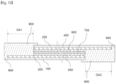
- FIGS. 6 to 13 are sectional views illustrating a process of fabricating the electrochromic element according to another embodiment.
- the first transparent electrode 300 is formed on the first substrate 100.
- the first transparent electrode 300 may be formed by a vacuum deposition process.
- a metal oxide such as indium tin oxide is deposited on the first substrate 100 by a sputtering process, etc., thereby forming the first transparent electrode 300.
- the first transparent electrode 300 may be formed by a coating process.
- the first substrate 100 may be coated with metal nanowires and a binder together, so that the first transparent electrode 300 may be formed.
- the first substrate 100 may be coated with a conductive polymer, so that the first transparent electrode 300 may be formed.
- the first transparent electrode 300 may be formed by a patterning process.
- a metal layer may be formed on the first substrate 100 by a sputtering process, etc., and the metal layer may be patterned to form the first transparent electrode 300 containing a metal mesh on the first substrate 100.
- the first color-changing layer 500 is formed on the first transparent electrode 300.
- the first color-changing layer 500 may be formed by a sol-gel coating process.
- a first sol solution including a first electrochromic material, a binder and a solvent may be coated on the first transparent electrode 300.
- a sol-gel reaction occurs in the coated first sol solution, and the first color-changing layer 500 may be formed.
- the first sol solution may include the first electrochromic material in a content of about 5 wt% to about 30 wt% in the form of particles.
- the first sol solution may include the binder in a content of about 5 wt% to about 30 wt%.
- the first sol solution may include the solvent in a content of about 60 wt% to about 90 wt%.
- the first sol solution may additionally include a dispersant.
- the solvent may be at least one selected from the group consisting of alcohols, ethers, ketones, esters and aromatic hydrocarbons.
- the solvent may be at least one selected from the group consisting of ethanol, propanol, butanol, hexanol, cyclohexanol, diacetone alcohol, ethylene glycol, diethylene glycol, glycerin, diethyl ether, ethylene glycol monomethyl ether, ethylene glycol monoethyl ether, ethylene glycol monobutyl ether, diethylene glycol monomethyl ether, diethylene glycol monoethyl ether, propylene glycol monomethyl ether, acetone, methyl ethyl ketone, acetylacetone, methyl isobutyl ketone, cyclohexanone, acetoacetic acid ester, methyl acetate, ethyl acetate, n-propyl acetate, i-butyl acetate, and
- the binder may be the inorganic binder as described above.
- the second transparent electrode 400 is formed on the second substrate 200.
- the second transparent electrode 400 may be formed by a vacuum deposition process.
- a metal oxide such as indium tin oxide may be deposited on the second substrate 200 by a sputtering process, etc., thereby forming the second transparent electrode 400.
- the second transparent electrode 400 may be formed by a coating process.
- the second substrate 200 may be coated with metal nanowires and a binder together, so that the second transparent electrode 400 may be formed.
- a conductive polymer may be coated on the second substrate 200, so that the second transparent electrode 400 may be formed.
- the second transparent electrode 400 may be formed by a patterning process.
- a metal layer may be formed on the second substrate 200 by a sputtering process, etc., and the metal layer is patterned so that the second transparent electrode 400 containing a metal mesh may be formed on the second substrate 200.
- the second color-changing layer 600 is formed on the second transparent electrode 400.
- the second color-changing layer 600 may be formed by a sol-gel coating process.
- a second sol solution containing a second electrochromic material, a binder and a solvent may be coated on the second transparent electrode 400.
- a sol-gel reaction may occur in the coated second sol solution, and the second color-changing layer 600 may be formed.
- the second sol solution may include the second electrochromic material in a content of about 5 wt% to about 30 wt% in the form of particles.
- the second sol solution may include the binder in a content of about 5 wt% to about 30 wt%.
- the second sol solution may include the solvent in a content of about 60 wt% to about 90 wt%.
- the second sol solution may additionally include a dispersant.
- an electrolyte composition for forming the electrolyte layer 700 is formed on the first color-changing layer 500.
- the electrolyte composition may include a metal salt, an electrolyte, a photocuable resin and a photocuable initiator.
- the photocuable resin may be at least one selected from the group consisting of hexandiol diacrylate (HDDA), tripropylene glycoldiacrylate (TPGDA), ethylene glycoldiacrylate (EGDA), trimethylolpropane triacrylate (TMPTA), trimethylolpropane ethoxylated triacrylate (TMPEOTA), glycerol propoxylated triacrylate (GPTA), pentaerythritol tetraacrylate (PETA) and dipentaerythritol hexaacrylate (DPHA).
- HDDA hexandiol diacrylate
- TPGDA tripropylene glycoldiacrylate
- EGDA ethylene glycoldiacrylate
- TMPTA trimethylolpropane triacrylate
- TMPEOTA trimethylolpropan
- the metal salt, the electrolyte and the photocuable initiator may be the same as described above.
- the second substrate 200, the second transparent electrode 400 and the second color-changing layer 600 are deposited on the coated electrolyte composition.
- the second color-changing layer 600 is brought into direct contact with the coated electrolyte composition.
- the coated electrolyte composition may be cured by light, and a first laminate including the first substrate 100, the first transparent electrode 300 and the first color-changing layer 500 and a second laminate including the second substrate 200, the second transparent electrode 400 and the second color-changing layer 600 are laminated to each other. That is, the first laminate and the second laminate may be adhered to each other by the electrolyte layer 700.
- a first open region OA1 is formed by removing portions of the first color-changing layer 500, the electrolyte layer 700, the second color-changing layer 600, the second transparent electrode 400 and the second substrate 200.
- the first open region OA1 exposes a portion of a top surface of the first transparent electrode 300.
- the second open region OA2 is formed by removing portions of the first substrate 100, the first transparent electrode 300, the first color-changing layer 500, the electrolyte layer 700 and the second color-changing layer 600.
- the second open region OA2 exposes a portion of a lower surface of the second transparent electrode 400.
- a first curable resin composition 801 is disposed in the first open region OA1.
- the first curable resin composition 801 may be continuously arranged from the top surface of the first transparent electrode 300 to the portion of the top surface of the second substrate 200. That is, the first curable resin composition 801 may cover one side surface of the first color-changing layer 500, one side surface of the electrolyte layer 700, one side surface of the second color-changing layer 600, one side surface of the second transparent electrode 400 and one side surface of the second substrate 200.
- a second curable resin composition 901 is disposed in the second open region OA2.
- the second curable resin composition 901 may be continuously disposed from the lower surface of the second transparent electrode 400 to the portion of the lower surface of the first substrate 100. That is, the second curable resin composition 901 may cover the other side surface of the first substrate 100, the other side surface of the first color-changing layer 500, the other side surface of the electrolyte layer 700, and the other side surface of the second color-changing layer 600.
- the first flattening member 10 is disposed on the first curable resin composition 801, and a predetermined pressure is applied to the first curable resin composition 801 by a first flattening member 10.
- the first flattening member 10 may be a film including a silicone release layer.
- a second flattening member 20 is disposed under the second curable resin composition 901, and a predetermined pressure is applied to the second curable resin composition 901 by the second flattening member 20.
- the second flattening member 20 may be a film including a silicone release layer.
- the first curable resin composition 201 is cured, and the first flattening member 10 is removed. Accordingly, the first seal part 800 is formed.
- the second curable resin composition 901 is cured, and the second flattening member 20 is removed. Accordingly, the second seal part 900 is formed.
- the first curable resin composition 801 and the second curable resin composition 901 may be simultaneously or sequentially cured. That is, the first curable resin composition 801 and the second curable resin composition 901 may be simultaneously applied and flattened, so that the first seal part 800 and the second seal part 900 may be simultaneously formed. Alternatively, the first curable resin composition 801 may be applied and cured, and then the first seal part 800 may be formed, and then the second curable resin composition may be applied and cured, so that the second seal part 900 may be formed.
- the electrochromic element according to another embodiment may be fabricated.
- FIG. 14 illustrates a sectional view of an electrochromic element according to another embodiment.
- the electrochromic element may further include a first barrier layer 1100 and a second barrier layer 1200.
- the first barrier layer 1100 is disposed on the first seal part 800.
- the first barrier layer 1100 is disposed on a first flat part.
- the first barrier layer 1100 may be in close contact with the first seal part 800.
- the first barrier layer 1100 may be attached to the first seal part 800.
- the first barrier layer 1100 may protect the first seal part 800 from external physical impact.
- the first barrier layer 1100 may protect the first transparent electrode 300, the first color-changing layer 500, the electrolyte layer 700, the second color-changing layer 600 and the second transparent electrode 400 from external moisture and/or oxygen. That is, the first barrier layer 1100 may reinforce the sealing characteristics of the first seal part 800.
- the first barrier layer 1100 may include a base film.
- the base film may include a polyester film, a polyethylene film, a polypropylene film, a polyimide film or a polyamide film.
- the first barrier layer 1100 may further include an organic film and inorganic film alternately arranged on the base film.
- the second barrier layer 1200 is disposed under the second seal part 900.
- the second barrier layer 1200 is disposed under a second flat part.
- the second barrier layer 1200 may be disposed under the second flat part to be in close contact therewith.
- the second barrier layer 1200 may be disposed under the second flat part to be attached thereto.
- the second barrier layer 1200 may protect the second seal part 900 from external physical impact.
- the second barrier layer 1200 may protect the second transparent electrode 400, the second color-changing layer 600, the electrolyte layer 700, the first color-changing layer 500 and the first transparent electrode 300 from external moisture and/or oxygen. That is, the second barrier layer 1200 may reinforce the sealing characteristics of the second seal part 900.
- the second barrier layer 1200 may include a base film.
- the base film may include a polyester film, a polyethylene film, a polypropylene film, a polyimide film or a polyamide film.
- the second barrier layer 1200 may further include an organic film and inorganic film alternately arranged on the base film.
- the first barrier layer 1100 and the second barrier layer 1200 may have a moisture permeability of about 1 ⁇ 10 g/m 2 ⁇ day or less.
- the first barrier layer 1100 and the second barrier layer 1200 may have a moisture permeability of about 5 g/m 2 ⁇ day or less.
- the first barrier layer 1100 and the second barrier layer 1200 may have a moisture permeability of about 5 ⁇ 10 -1g/m 2 ⁇ day or less.
- the first barrier layer 1100 and the second barrier layer 1200 may have a moisture permeability of about 1 ⁇ 10 -1g/m 2 ⁇ day or less.
- the first barrier layer 1100 and the second barrier layer 1200 may be attached to the first seal part 800 and the second seal part 900. That is, the first barrier layer 1100 may be brought into close contact with the first seal part 800 in a process of curing the first curable resin. In addition, the second barrier layer 1200 may be brought into close contact with the second seal part 900 in a process of curing the second curable resin.
- FIG. 15 illustrates a sectional view of an electrochromic element according to still another embodiment.
- the first seal part 800 further includes a first edge 840.
- the first edge 840 extends from the first body 810, and covers a first side surface of the first substrate 100 and a seventh side surface of the first transparent electrode 300.
- the first curable resin composition 801 may flow to the first side surface 101 and may be cured, so that the first edge 840 may be formed.
- the second seal part 900 further includes a second edge 940.
- the second edge 940 extends from the second body 910 and covers the fourth side surface 202 of the second substrate 200 and the eighth side surface of the second transparent electrode 400.
- the second curable resin composition 901 may flow to the fourth side surface 202 and may be cured, so that the second edge 940 may be formed.
- first seal part 800 includes the first edge 840
- second seal part 900 includes the second edge 940
- the first seal part 800 and the second seal part 900 may effectively protect the first transparent electrode 300, the first color-changing layer 500, the electrolyte layer 700, the second color-changing layer 600 and the second transparent electrode 400.
- first seal part 800 and the second seal part 900 respectively cover the first side surface 101 and the fourth side surface 202, the mechanical strength of the edge portions of the electrochromic element according to another embodiment may be further reinforced.
- the electrochromic element includes the first seal part 800 disposed in the first open region OA1 from which the second substrate 200, the second transparent electrode 400 and the electrolyte layer 700 have been removed and the top surface of the first transparent electrode 300 is open.
- the first seal part 800 may be attached to the top surface of the first transparent electrode 300 while being disposed on the third side surface 201 of the second substrate 200, the side surface of the second transparent electrode 400, the side surface of the second color-changing layer 600, the side surface of the electrolyte layer 700 and the side surface of the first color-changing layer 500.
- the first seal part 800 may be attached to the third side surface 201 of the second substrate 200, the side surface of the second transparent electrode 400, the side surface of the second color-changing layer 600, the side surface of the electrolyte layer 700 and the side surface of the first color-changing layer 500.
- the first seal part 800 may also be attached to the portion of the top surface of the second substrate 200.
- the first seal part 800 may be disposed over a wide area and may be attached to the wide area. Accordingly, the first seal part 800 may be firmly attached to the top surface of the first transparent electrode 300, the third side surface 201 of the second substrate 200, the side surface of the second transparent electrode 400, the side surface of the second color-changing layer 600, the side surface of the electrolyte layer 700, the side surface of the first color-changing layer 500 and the portion of the top surface of the second substrate 200.
- first seal part 800 may be firmly brought into close contact with the top surface of the first transparent electrode 300, the third side surface 201 of the second substrate 200, the side surface of the second transparent electrode 400, the side surface of the second color-changing layer 600, the side surface of the electrolyte layer 700, the side surface of the first color-changing layer 500 and the portion of the top surface of the second substrate 200.
- the first seal part 800 may efficiently suppress oxygen and moisture penetrating from the side.
- the second seal part 900 may be disposed in the second open region OA2 from which the first substrate 100, the first transparent electrode 300 and the electrolyte layer 700 have been removed and the lower surface of the second transparent electrode 400 is open.
- the second seal part 900 may be attached to the second side surface 102 of the first substrate 100, the side surface of the first transparent electrode 300, the side surface of the first color-changing layer 500, the side surface of the electrolyte layer 700 and the side surface of the second color-changing layer 600.
- the second seal part 900 may also be attached to the portion of the lower surface of the first substrate 100.
- the second seal part 900 may efficiently suppress oxygen and moisture penetrating from the side.
- the electrochromic element may block the inflow of oxygen and moisture from the outside, and may effectively protect the first color-changing layer 500, the electrolyte layer 700 and the second color-changing layer 600.
- first substrate 100 and the second substrate 200 may be flexible, and the electrochromic element according to another embodiment may be bent.
- the electrochromic element according to another embodiment may prevent the first seal part 800 and the second seal part 900 from being peeled off or gapped.
- the electrochromic element according to another embodiment may have improved durability.
- Embodiments can be used in the field of smart windows.
Landscapes
- Physics & Mathematics (AREA)
- Nonlinear Science (AREA)
- General Physics & Mathematics (AREA)
- Optics & Photonics (AREA)
- Mathematical Physics (AREA)
- Chemical & Material Sciences (AREA)
- Crystallography & Structural Chemistry (AREA)
- Electrochromic Elements, Electrophoresis, Or Variable Reflection Or Absorption Elements (AREA)
Abstract
Description
- Embodiments relate to an electrochromic element and a method of fabricating the same.
- Electrochromic films, whose colors change due to coloring and discoloring through oxidation-reduction reactions at each oxidation electrode and reduction electrode depending on an applied potential, can be artificially controlled by a user to emit visible light and infrared rays, and various types of inorganic oxides are used as electrode materials.
- Electrochromic films as described above have been developed in various ways and patent-applied. As examples of related patent applications, there are
Korea Patent Application Publication No. 10-2001-0087586 Korea Utility Model Publication No. 0184841 - Therefore, the present invention has been made in view of the above problems, and it is one object of the present invention to provide an electrochromic element having improved durability and a method of fabricating the same.
- In accordance with an aspect of the present invention, the above and other objects can be accomplished by the provision of an electrochromic element, including: a first substrate; a first transparent electrode disposed on the first substrate; a first color-changing layer disposed on the first transparent electrode; an electrolyte layer disposed on the first color-changing layer; a second color-changing layer disposed on the electrolyte layer; a second transparent electrode disposed on the second color-changing layer; a second substrate disposed on the second transparent electrode; and a first seal part disposed in a first open region between a third side surface of the second substrate and a first side surface of the first substrate and configured to cover portions of a top surface of the first transparent electrode, a fifth side surface of the electrolyte layer, a third side surface of the second substrate and a top surface of the second substrate.
- In an embodiment, the first seal part may further include a first flattening part having a step difference from a top surface of the second substrate.
- In an embodiment the first seal part may include a first body disposed in the first open region; and a first extension extending from the first body to the top surface of the second substrate.
- In an embodiment, the first substrate may include a third side surface facing the first side surface, the second substrate may include a fourth side surface facing the third side surface, a second open region may be formed between the third side surface and the fourth side surface, and a second seal part disposed in the second open region and configured to cover portions of a lower surface of the second transparent electrode, a sixth side surface of the electrolyte layer, the third side surface and a lower surface of the first substrate may be further included.
- In an embodiment, the second seal part may further include a second flattening part having a step difference from a lower surface of the first substrate.
- In an embodiment, the second seal part may include a second body disposed in the second open region; and a second extension extending from the second body to a lower surface of the first substrate.
- The electrochromic element according to an embodiment may further include a first barrier layer disposed on the first flattening part.
- The electrochromic element according to an embodiment may further include a second barrier layer disposed under the second flattening part.
- The electrochromic element according to an embodiment may further include a first bus bar connected electrically to the first transparent electrode layer, wherein the first seal part covers the first bus bar.
- The electrochromic element according to an embodiment may further include a second bus bar electrically connected to the second transparent electrode layer, wherein the second seal part covers the second bus bar.
- In accordance with another aspect of the present invention, provided is a method of fabricating an electrochromic element, the method including: forming a first transparent electrode on a first substrate; forming a first color-changing layer on the first transparent electrode layer; forming an electrolyte layer on the first color-changing layer; forming a second transparent electrode on a second substrate; forming a second color-changing layer on the second transparent electrode; disposing the second color-changing layer on the electrolyte layer and bonding the second substrate, the second transparent electrode and the second color-changing layer to the electrolyte layer; removing a portion of the second substrate, a portion of the second transparent electrode, a portion of the second color-changing layer, a portion of the electrolyte layer and a portion of the first color-changing layer to form a first open region; disposing a first curable resin in the first open region; flattening the first curable resin; and curing the first curable resin.
- The method of fabricating an electrochromic element according to an embodiment may further include: removing a portion of the first substrate, a portion of the first transparent electrode, a portion of the first color-changing layer, a portion of the electrolyte layer and a portion of the second color-changing layer to form a second open region; disposing a second curable resin in the second open region; flattening the second curable resin; and curing the second curable resin.
- An electrochromic element according to an embodiment includes a first seal part disposed in a first open region from which a second substrate, a second transparent electrode and an electrolyte layer have been removed and a top surface of a first transparent electrode is open.
- Accordingly, the first seal part can be attached to the top surface of the first transparent electrode while being disposed on a third side surface of the second substrate, a side surface of the second transparent electrode, a side surface of the second color-changing layer, a side surface of the electrolyte layer and a side surface of the first color-changing layer. In addition, the first seal part can be attached to the third side surface of the second substrate, the side surface of the second transparent electrode, the side surface of the second color-changing layer, the side surface of the electrolyte layer and the side surface of the first color-changing layer. In addition, the first seal part can be attached to a portion of a top surface of the second substrate.
- Accordingly, the first seal part can be disposed over a wide area, and can be attached to the wide area. Accordingly, the first seal part may be firmly attached to portions of the top surface of the first transparent electrode, the third side surface of the second substrate, the side surface of the second transparent electrode, the side surface of the second color-changing layer, the side surface of the electrolyte layer, the side surface of the first color-changing layer and the top surface of the second substrate. In addition, the first seal part may be firmly brought into close contact with portions of the top surface of the first transparent electrode, the third side surface of the second substrate, the side surface of the second transparent electrode, the side surface of the second color-changing layer, the side surface of the electrolyte layer, the side surface of the first color-changing layer and the top surface of the second substrate.
- Therefore, the first seal part can effectively suppress oxygen and moisture penetrating from the side.
- Similarly, the second seal part can be disposed in a second open region from which the first substrate, the first transparent electrode and the electrolyte layer have been removed and a lower surface of the second transparent electrode is open.
- In addition, the second seal part can be attached to a second side surface of the first substrate, a side surface of the first transparent electrode, a side surface of the first color-changing layer, a side surface of the electrolyte layer and a side surface of the second color-changing layer. In addition, the second seal part can also be attached to a portion of a lower surface of the first substrate.
- Accordingly, the second seal part can efficiently suppress oxygen and moisture penetrating from the side.
- Therefore, the electrochromic element according to another embodiment can block the inflow of oxygen and moisture from the outside and can effectively protect the first color-changing layer, the electrolyte layer and the second color-changing layer.
- In addition, the first substrate and the second substrate can be flexible, and the electrochromic element according to another embodiment can be bent. Here, since the first seal part and the second seal part are strongly adhered to each side, the electrochromic element according to another embodiment can prevent the first seal part and the second seal part from being peeled off or gapped.
- The electrochromic element according to an embodiment can have improved durability.
-
-
FIG. 1 illustrates a plan view of an electrochromic element according to an embodiment. - IG. 2 illustrates a sectional view taken along line A-A' of
FIG. 1 . -
FIG. 3 illustrates an enlarged sectional view of a first extension. -
FIG. 4 illustrates an enlarged sectional view of a second extension. -
FIG. 5 illustrates a cross-sectional view of an electrochromic element according to another embodiment. -
FIGS. 6 to 13 are sectional views illustrating a process of fabricating the electrochromic element according to an embodiment. -
FIG. 14 illustrates a sectional view of an electrochromic element according to another embodiment. -
FIG. 15 illustrates a sectional view of an electrochromic element according to still another embodiment. - the description of embodiments, it will be understood that when each part, surface, layer or substrate is referred to as being "on" or "under" another part, surface, layer or substrate, the part, surface, layer or substrate can be directly on another part, surface, layer or substrate or intervening part, surface, layer or substrate, and criteria for "on" and "under" will be provided based on the drawings. Elements in the following drawings may be exaggerated, omitted, or schematically illustrated for conveniences and clarity of explanation, and the sizes of elements do not reflect their actual sizes completely.
-
FIG. 1 illustrates a plan view of an electrochromic element according to an embodiment.FIG. 2 illustrates a sectional view taken along line A-A' ofFIG. 1 .FIG. 3 illustrates an enlarged sectional view of a first extension.FIG. 4 illustrates an enlarged sectional view of a second extension.FIG. 5 illustrates a cross-sectional view of an electrochromic element according to another embodiment. - Referring to
FIGS. 1 to 4 , the electrochromic element according to another embodiment includes afirst substrate 100, asecond substrate 200, a firsttransparent electrode 300, a secondtransparent electrode 400, a first color-changinglayer 500, a second color-changinglayer 600, anelectrolyte layer 700, afirst seal part 800 and asecond seal part 900. - The
first substrate 100 supports the firsttransparent electrode 300, the first color-changinglayer 500, the second color-changinglayer 600, the secondtransparent electrode 400 and theelectrolyte layer 700 together with thesecond substrate 200. - In addition, the first
transparent electrode 300, the first color-changinglayer 500, the second color-changinglayer 600, the secondtransparent electrode 400 and theelectrolyte layer 700 are sandwiched between thefirst substrate 100 and thesecond substrate 200. Thefirst substrate 100 protects the firsttransparent electrode 300, the first color-changinglayer 500, the second color-changinglayer 600, the secondtransparent electrode 400 and theelectrolyte layer 700 from external physical impact and chemical impact together with thesecond substrate 200. - The
first substrate 100 may include a polymer resin. Thefirst substrate 100 may include at least one selected from the group consisting of a polyester-based resin, a polyimide-based resin, a cyclic olefin polymer resin, a polyethersulfone, a polycarbonate and a polyolefin-based resin. - The
first substrate 100 may include a polyester resin as a main component. Thefirst substrate 100 may include polyethylene terephthalate. Thefirst substrate 100 may include the polyethylene terephthalate in a content of about 90 wt% or more based on the total composition amount. Thefirst substrate 100 may include the polyethylene terephthalate in a content of about 95 wt% or more based on the total composition amount. Thefirst substrate 100 may include the polyethylene terephthalate in a content of about 97 wt% or more based on the total composition amount. Thefirst substrate 100 may include the polyethylene terephthalate in a content of about 98 wt% or more based on the total composition amount. - The
first substrate 100 may include a uniaxially or biaxially stretched polyethylene terephthalate film. Thefirst substrate 100 may include a polyethylene terephthalate film stretched about 2 to about 5 times in a longitudinal direction and/or width direction. - The
first substrate 100 may have high mechanical properties to reinforce the glass when applied to a window of a building or a vehicle. - The
first substrate 100 may have a tensile strength of about 7 kgf/mm2 to about 40 kgf/mm2 in the longitudinal direction. Thefirst substrate 100 may have a tensile strength of about 8 kgf/mm2 to about 35 kgf/mm2 in the longitudinal direction. - The
first substrate 100 may have a tensile strength of about 7 kgf/mm2 to about 40 kgf/mm2 in the width direction. Thefirst substrate 100 may have a tensile strength of about 8 kgf/mm2 to about 35 kgf/mm2 in the width direction. - The
first substrate 100 may have a modulus of about 200 kgf/mm2 to about 400 kgf/mm2 in the longitudinal direction. Thefirst substrate 100 may have a modulus of about 250 kgf/mm2 to about 350 kgf/mm2 in the longitudinal direction. Thefirst substrate 100 may have a modulus of about 250 kgf/mm2 to about 270 kgf/mm2 in the longitudinal direction. - The
first substrate 100 may have a modulus of about 200 kgf/mm2 to about 400 kgf/mm2 in the width direction. Thefirst substrate 100 may have a modulus of about 250 kgf/mm2 to about 350 kgf/mm2 in the width direction. Thefirst substrate 100 may have a modulus of about 250 kgf/mm2 to about 270 kgf/mm2 in the width direction. - The
first substrate 100 may have a fracture elongation of about 30% to about 150% in the longitudinal direction. Thefirst substrate 100 may have a fracture elongation of about 30% to about 130% in the longitudinal direction. Thefirst substrate 100 may have a fracture elongation of about 40% to about 120% in the longitudinal direction. - The
first substrate 100 may have a fracture elongation of about 30% to about 150% in the longitudinal direction. Thefirst substrate 100 may have a fracture elongation of about 30% to about 130% in the longitudinal direction. Thefirst substrate 100 may have a fracture elongation of about 40% to about 120% in the longitudinal direction. - The
first substrate 100 may have a fracture elongation of about 30% to about 150% in the width direction. Thefirst substrate 100 may have a fracture elongation of about 30% to about 130% in the width direction. Thefirst substrate 100 may have a fracture elongation of about 40% to about 120% in the width direction. - The modulus, the fracture elongation and the tensile strength may be measured according to KS B 5521.
- In addition, the modulus, the tensile strength and the fracture elongation may be measured according to ASTM D882.
- Since the
first substrate 100 has the improved mechanical strength as described above, it can effectively protect the firsttransparent electrode 300, the secondtransparent electrode 400, the first color-changinglayer 500, the second color-changinglayer 600 and theelectrolyte layer 700. In addition, since thefirst substrate 100 has the improved mechanical strength as described above, the mechanical strength of glass to be attached may be effectively reinforced. - In addition, the
first substrate 100 may have high chemical resistance. Accordingly, even if an electrolyte contained in thefirst substrate 100 leaks, damage to the surface of thefirst substrate 100 may be minimized. - The
first substrate 100 may have improved optical properties. A total light transmittance of thefirst substrate 100 may be about 55% or more. The total light transmittance of thefirst substrate 100 may be about 70% or more. The total light transmittance of thefirst substrate 100 may be about 75% to about 99%. The total light transmittance of thefirst substrate 100 may be about 80% to about 99%. - A haze of the
first substrate 100 may be about 20% or less. The haze of thefirst substrate 100 may be about 0.1% to about 20%. The haze of thefirst substrate 100 may be about 0.1% to about 10%. The haze of thefirst substrate 100 may be about 0.1% to about 7%. - The total light transmittance and the haze may be measured according to ASTM D 1003, etc.
- Since the
first substrate 100 has an appropriate total light transmittance and haze, the electrochromic element according to another embodiment may have improved optical properties. That is, since thefirst substrate 100 has an appropriate transmittance and haze, an improved appearance may be achieved by minimizing distortion of images from the outside while appropriately controlling a transmittance when the electrochromic element according to another embodiment is applied to a window. - In addition, the
first substrate 100 may have an in-plane phase difference of about 100 nm to about 4000 nm. Thefirst substrate 100 may have an in-plane phase difference of about 200 nm to about 3500 nm. Thefirst substrate 100 may have an in-plane phase difference of about 200 nm to about 3000 nm. - The
first substrate 100 may have an in-plane phase difference of about 7000 nm or more. Thefirst substrate 100 may have an in-plane phase difference of about 7000 nm to about 50000 nm. Thefirst substrate 100 may have an in-plane phase difference of about 8000 nm to about 20000 nm. - The in-plane phase difference may be derived from a refractive index and thickness according to the direction of the
first substrate 100. - Since the
first substrate 100 has the in-plane phase difference as described above, the electrochromic element according to another embodiment may have an improved appearance. - The thickness of the
first substrate 100 may be about 10 µm to about 200 µm. The thickness of thefirst substrate 100 may be about 23 µm to about 150 µm. The thickness of thefirst substrate 100 may be about 30 µm to about 120 µm. - The
first substrate 100 may include an organic filler or an inorganic filler. The organic filler or the inorganic filler may function as an anti-blocking agent. - The average particle diameter of the filler may be about 0.1 µm to about 5 µm. The average particle diameter of the filler may be about 0.1 µm to about 3 µm. The average particle diameter of the filler may be about 0.1 µm to about 1µm.
- The filler may be at least one selected from the group consisting of silica particles, barium sulfate particles, alumina particles and titania particles.
- In addition, the filler may be included in the
first substrate 100 in a content of about 0.01 wt% to about 3 wt% based on the total amount of thefirst substrate 100. The filler may be included in thefirst substrate 100 in a content of about 0.05 wt% to about 2 wt% based on the total amount of thefirst substrate 100. - The
first substrate 100 may have a single-layer structure. For example, thefirst substrate 100 may be a single-layer polyester film. - The
first substrate 100 may have a multi-layer structure. For example, thefirst substrate 100 may be a multi-layer co-extruded film. The multi-layer co-extruded structure may include a center layer, a first surface layer and a second surface layer. The filler may be included in the first surface layer and the second surface layer. - The
second substrate 200 faces thefirst substrate 100. Thesecond substrate 200 is disposed on thefirst substrate 100. One end of thesecond substrate 200 may be disposed to be misaligned with one end of thefirst substrate 100. The other end of thesecond substrate 200 may be disposed to be misaligned with the other end of thefirst substrate 100. - The
second substrate 200 supports the firsttransparent electrode 300, the first color-changinglayer 500, the second color-changinglayer 600, the secondtransparent electrode 400 and theelectrolyte layer 700 together with thefirst substrate 100. - In addition, the first
transparent electrode 300, the first color-changinglayer 500, the second color-changinglayer 600, the secondtransparent electrode 400 and theelectrolyte layer 700 are sandwiched between thesecond substrate 200 and thefirst substrate 100. Thesecond substrate 200 may protect the firsttransparent electrode 300, the first color-changinglayer 500, the second color-changinglayer 600, the secondtransparent electrode 400 and theelectrolyte layer 700 from external physical impact and chemical impact together with thefirst substrate 100. - The
second substrate 200 may include a polymer resin. Thesecond substrate 200 may include at least one selected from the group consisting of a polyester-based resin, a polyimide-based resin, a cyclic olefin polymer resin, a polyethersulfone, a polycarbonate and a polyolefin-based resin. - The
second substrate 200 may include a polyester resin as a main component. Thesecond substrate 200 may include polyethylene terephthalate. Thesecond substrate 200 may include the polyethylene terephthalate in a content of about 90 wt% or more based on the total composition amount. Thesecond substrate 200 may include the polyethylene terephthalate in a content of about 95 wt% or more based on the total composition amount. Thesecond substrate 200 may include the polyethylene terephthalate in a content of about 97 wt% or more based on the total composition amount. Thesecond substrate 200 may include the polyethylene terephthalate in a content of about 98 wt% or more based on the total composition amount. - The
second substrate 200 may include a uniaxially or biaxially stretched polyethylene terephthalate film. Thesecond substrate 200 may include a polyethylene terephthalate film stretched about 2 to about 5 times in a longitudinal direction and/or width direction. - The
second substrate 200 may have high mechanical properties to reinforce the glass when applied to a window of a building or a vehicle. - The
second substrate 200 may have a tensile strength of about 7 kgf/mm2 to about 40 kgf/mm2 in the longitudinal direction. Thesecond substrate 200 may have a tensile strength of about 8 kgf/mm2 to about 35 kgf/mm2 in the longitudinal direction. - The
second substrate 200 may have a tensile strength of about 7 kgf/mm2 to about 40 kgf/mm2 in the width direction. Thesecond substrate 200 may have a tensile strength of about 8 kgf/mm2 to about 35 kgf/mm2 in the width direction. - The
second substrate 200 may have a modulus of about 200 kgf/mm2 to about 400 kgf/mm2 in the longitudinal direction. Thesecond substrate 200 may have a modulus of about 250 kgf/mm2 to about 350 kgf/mm2 in the longitudinal direction. Thesecond substrate 200 may have a modulus of about 250 kgf/mm2 to about 270 kgf/mm2 in the longitudinal direction. - The
second substrate 200 may have a modulus of about 200 kgf/mm2 to about 400 kgf/mm2 in the width direction. Thesecond substrate 200 may have a modulus of about 250 kgf/mm2 to about 350 kgf/mm2 in the width direction. Thesecond substrate 200 may have a modulus of about 250 kgf/mm2 to about 270 kgf/mm2 in the width direction. - The
second substrate 200 may have a fracture elongation of about 30% to about 150% in the longitudinal direction. Thesecond substrate 200 may have a fracture elongation of about 30% to about 130% in the longitudinal direction. Thesecond substrate 200 may have a fracture elongation of about 40% to about 120% in the longitudinal direction. - The
second substrate 200 may have a fracture elongation of about 30% to about 150% in the longitudinal direction. Thesecond substrate 200 may have a fracture elongation of about 30% to about 130% in the longitudinal direction. Thesecond substrate 200 may have a fracture elongation of about 40% to about 120% in the longitudinal direction. - The
second substrate 200 may have a fracture elongation of about 30% to about 150% in the width direction. Thesecond substrate 200 may have a fracture elongation of about 30% to about 130% in the width direction. Thesecond substrate 200 may have a fracture elongation of about 40% to about 120% in the width direction. - Since the
second substrate 200 has the improved mechanical strength as described above, it can effectively protect the firsttransparent electrode 300, the secondtransparent electrode 400, the first color-changinglayer 500, the second color-changinglayer 600 and theelectrolyte layer 700. In addition, since thesecond substrate 200 has the improved mechanical strength as described above, the mechanical strength of glass to be attached may be effectively reinforced. - In addition, the
second substrate 200 may have high chemical resistance. Accordingly, even if an electrolyte contained in thesecond substrate 200 leaks, damage to the surface of thesecond substrate 200 may be minimized. - The
second substrate 200 may have improved optical properties. A total light transmittance of thesecond substrate 200 may be about 55% or more. The total light transmittance of thesecond substrate 200 may be about 70% or more. The total light transmittance of thesecond substrate 200 may be about 75% to about 99%. The total light transmittance of thesecond substrate 200 may be about 80% to about 99%. - A haze of the
second substrate 200 may be about 20% or less. The haze of thesecond substrate 200 may be about 0.1% to about 20%. The haze of thesecond substrate 200 may be about 0.1% to about 10%. The haze of thesecond substrate 200 may be about 0.1% to about 7%. - Since the
second substrate 200 has an appropriate total light transmittance and haze, the electrochromic element according to another embodiment may have improved optical properties. That is, since thesecond substrate 200 has an appropriate transmittance and haze, an improved appearance may be achieved by minimizing distortion of images from the outside while appropriately controlling a transmittance when the electrochromic element according to another embodiment is applied to a window. - In addition, the
second substrate 200 may have an in-plane phase difference of about 100 nm to about 4000 nm. Thesecond substrate 200 may have an in-plane phase difference of about 200 nm to about 3500 nm. Thesecond substrate 200 may have an in-plane phase difference of about 200 nm to about 3000 nm. - The
second substrate 200 may have an in-plane phase difference of about 7000 nm or more. Thesecond substrate 200 may have an in-plane phase difference of about 7000 nm to about 50000 nm. Thesecond substrate 200 may have an in-plane phase difference of about 8000 nm to about 20000 nm. - The in-plane phase difference may be derived from a refractive index and thickness according to the direction of the
second substrate 200. - The thickness of the
second substrate 200 may be about 10 µm to about 200 µm. The thickness of thesecond substrate 200 may be about 23 µm to about 150 µm. The thickness of thesecond substrate 200 may be about 30 µm to about 120 µm. - The
second substrate 200 may include an organic filler or an inorganic filler. The organic filler or the inorganic filler may function as an anti-blocking agent. - The average particle diameter of the filler may be about 0.1 µm to about 5 µm. The average particle diameter of the filler may be about 0.1 µm to about 3 µm. The average particle diameter of the filler may be about 0.1 µm to about 1µm.
- The filler may be at least one selected from the group consisting of silica particles, barium sulfate particles, alumina particles and titania particles.
- The filler may be at least one selected from the group consisting of silica particles, barium sulfate particles, alumina particles and titania particles.
- In addition, the filler may be included in the
second substrate 200 in a content of about 0.01 wt% to about 3 wt% based on the total amount of thesecond substrate 200. The filler may be included in thesecond substrate 200 in a content of about 0.05 wt% to about 2 wt% based on the total amount of thesecond substrate 200. - The
second substrate 200 may have a single-layer structure. For example, thesecond substrate 200 may be a single-layer polyester film. - The
second substrate 200 may have a multi-layer structure. For example, thesecond substrate 200 may be a multi-layer co-extruded film. - The
first substrate 100 and thesecond substrate 200 may be flexible. Accordingly, the electrochromic element according to another embodiment may be flexible overall. - The first
transparent electrode 300 is disposed on thefirst substrate 100. The firsttransparent electrode 300 may be deposited on thefirst substrate 100. In addition, a hard coating layer may be further included between the firsttransparent electrode 300 and thefirst substrate 100. - The first
transparent electrode 300 may include at least one selected from the group consisting of tin oxide, zinc oxide, silver (Ag), chromium (Cr), indium tin oxide (ITO), fluorine-doped tin oxide (FTO), aluminum-doped zinc oxide (AZO), gallium-doped zinc oxide (GZO), antimony-doped tin oxide (ATO), indium zinc oxide (IZO), niobium-doped titanium oxide (NTO) and cadmium tin oxide (CTO). - In addition, the first
transparent electrode 300 may include graphene, silver nanowires and/or metal mesh. - The first
transparent electrode 300 may have a total light transmittance of about 80% or more. The firsttransparent electrode 300 may have a total light transmittance of about 85% or more. The firsttransparent electrode 300 may have a total light transmittance of about 88% or more. - the first
transparent electrode 300 may have a haze of about 10% or less. The firsttransparent electrode 300 may have a haze of about 7% or less. The firsttransparent electrode 300 may have a haze of about 5% or less. - A surface resistance of the first
transparent electrode 300 may be about 1 Ω/sq to 60 Ω/sq. The surface resistance of the firsttransparent electrode 300 may be about 1 Ω/sq to 40 Ω/sq. The surface resistance of the firsttransparent electrode 300 may be about 1 Ω/sq to 30 Ω/sq. - The thickness of the first
transparent electrode 300 may be about 50 nm to about 50 µm. The thickness of the firsttransparent electrode 300 may be about 100 nm to about 10 µm. The thickness of the firsttransparent electrode 300 may be about 150 nm to about 5 µm. - The first
transparent electrode 300 is electrically connected to the first color-changinglayer 500. In addition, the firsttransparent electrode 300 is electrically connected to theelectrolyte layer 700 through the first color-changinglayer 500. - The second
transparent electrode 400 is disposed under thesecond substrate 200. The secondtransparent electrode 400 may be deposited on thesecond substrate 200. In addition, a hard coating layer may be further included between the secondtransparent electrode 400 and thesecond substrate 200. - The second
transparent electrode 400 may include at least one selected from the group consisting of tin oxide, zinc oxide, silver (Ag), chromium (Cr), indium tin oxide (ITO), fluorine-doped tin oxide (FTO), aluminum-doped zinc oxide (AZO), gallium-doped zinc oxide (GZO), antimony-doped tin oxide (ATO), indium zinc oxide (IZO), niobium-doped titanium oxide (NTO) and cadmium tin oxide (CTO). - In addition, the second
transparent electrode 400 may include graphene, silver nanowires and/or metal mesh. - The second
transparent electrode 400 may have a total light transmittance of about 80% or more. The secondtransparent electrode 400 may have a total light transmittance of about 85% or more. The secondtransparent electrode 400 may have a total light transmittance of about 88% or more. - The second
transparent electrode 400 may have a haze of about 10% or less. The secondtransparent electrode 400 may have a haze of about 7% or less. The secondtransparent electrode 400 may have a haze of about 5% or less. - A surface resistance of the second
transparent electrode 400 may be about 1 Ω/sq to about 60 Ω/sq. The surface resistance of the secondtransparent electrode 400 may be about 1 Ω/sq to about 40 Ω/sq. The surface resistance of the secondtransparent electrode 400 may be about 1 Ω/sq to about 30 Ω/sq. - The thickness of the second
transparent electrode 400 may be about 50 nm to about 50 µm. The thickness of the secondtransparent electrode 400 may be about 100 nm to about 10 µm. The thickness of the secondtransparent electrode 400 may be about 150 nm to about 5 µm. - The second
transparent electrode 400 is electrically connected to the second color-changinglayer 600. In addition, the secondtransparent electrode 400 is electrically connected to theelectrolyte layer 700 through the second color-changinglayer 600. - The first color-changing
layer 500 is disposed on the firsttransparent electrode 300. The first color-changinglayer 500 may be directly disposed on a top surface of the firsttransparent electrode 300. The first color-changinglayer 500 may be electrically directly connected to the firsttransparent electrode 300. - The first color-changing
layer 500 is electrically connected to the firsttransparent electrode 300. The first color-changinglayer 500 may be directly connected to the firsttransparent electrode 300. In addition, the first color-changinglayer 500 is electrically connected to theelectrolyte layer 700. The first color-changinglayer 500 may be electrically connected to theelectrolyte layer 700. - The color of the first color-changing
layer 500 may be changed when supplied with electrons. The first color-changinglayer 500 may include a first electrochromic material whose color is changed when supplied with electrons. The first electrochromic material may include at least one selected from the group consisting of tungsten oxide, niobium pentoxide, vanadium pentoxide, titanium oxide, molybdenum oxide, vilogen and poly(3,4-ethylenedioxythiophene (PEDOT). - The first color-changing
layer 500 may include the first electrochromic material in the form of particles. The tungsten oxide, niobium pentoxide, vanadium pentoxide, titanium oxide and molybdenum oxide may be particles having a particle diameter of about 1nm to about 200 nm. - In addition, the first color-changing
layer 500 may further include a binder. The binder may be an inorganic binder. The binder may include a silica gel. The binder may be formed by a silica sol containing tetramethoxysilane or methyltrimethoxysilane. - The second color-changing
layer 600 is disposed under the secondtransparent electrode 400. The second color-changinglayer 600 may be directly disposed on a lower surface of the secondtransparent electrode 400. The second color-changinglayer 600 may be electrically directly connected to the secondtransparent electrode 400. - The second color-changing
layer 600 is electrically connected to the secondtransparent electrode 400. The second color-changinglayer 600 may be directly connected to the secondtransparent electrode 400. In addition, the second color-changinglayer 600 is electrically connected to theelectrolyte layer 700. The second color-changinglayer 600 may be electrically connected to theelectrolyte layer 700. - The color of the second color-changing
layer 600 may be changed when losing electrons. The second color-changinglayer 600 may include a second electrochromic material that is oxidized and color-changed while losing electrons. The second color-changinglayer 600 may include at least one selected from the group consisting of Prussian blue, nickel oxide and iridium oxide. - The second color-changing
layer 600 may include the second electrochromic material in the form of particles. The Prussian blue, nickel oxide and iridium oxide may be particles having a particle diameter of about 1nm to about 200 nm. - In addition, the second color-changing
layer 600 may further include the binder. - The
electrolyte layer 700 may be disposed on the first color-changinglayer 500. In addition, theelectrolyte layer 700 is disposed under the second color-changinglayer 600. Theelectrolyte layer 700 may be disposed between the first color-changinglayer 500 and the second color-changinglayer 600. - The
electrolyte layer 700 may include a solid polymer electrolyte containing metal ions, an inorganic hydrate, etc. Theelectrolyte layer 700 may include lithium ions (Li+), sodium ions (Na+), potassium ions (K+), etc. - Specifically, poly-AMPS, PEO/LiCF3SO3, etc. may be used as the solid polymer electrolyte, and Sb2O5 • 4H2O, etc. may be used as the inorganic hydrate.
- In addition, the
electrolyte layer 700 is a configuration that provides electrolyte ions involved in an electrochromic reaction. The electrolyte ions may be, for example, monovalent cations such as H+, Li+, Na+, K+, Rb+ or Cs+. - The
electrolyte layer 700 may include an electrolyte. For example, a liquid electrolyte, a gel polymer electrolyte, an inorganic solid electrolyte, etc. may be used as the electrolyte without limitation. In addition, the electrolyte may be used in the form of a single layer or film so as to be laminated together with the electrode or the substrate. - The type of electrolyte salt used in the
electrolyte layer 700 is not particularly limited so long as it is a compound capable of providing monovalent cations, i.e., H+, Li+, Na+, K+, Rb+ or Cs+. For example, theelectrolyte layer 700 may include a lithium salt compound such as LiClO4, LiBF4, LiAsF6, LiPF6, LiCl, LiBr, LiI, LiB10Cl10, LiCF3SO3, LiCF3CO2, LiAsF6, LiSbF6, LiAlCl4, CH3SO3Li, CF 3SO3Li or (CF3SO2)2NLi; or a sodium salt compound such as NaClO4. - In one example, the
electrolyte layer 700 may include a compound containing Cl or F element as an electrolyte salt. Specifically, theelectrolyte layer 700 may include at least one electrolyte salt selected from among LiClO4, LiBF4, LiAsF6, LiPF6, LiCl, LiB10Cl10, LiCF3SO3, LiCF3CO2, LiAsF6, LiSbF6, LiAlCl4, CF3SO3Li, (CF3SO2)2NLi and NaClO4. - The electrolyte may additionally include a carbonate compound as a solvent. Since a carbonate compound has a high dielectric constant, it may increase ionic conductivity. As a non-limiting example, a solvent such as propylene carbonate (PC), ethylene carbonate (EC), dimethyl carbonate (DMC), diethyl carbonate (DEC) or ethylmethyl carbonate (EMC) may be used as a carbonate compound.
- In another example, when the
electrolyte layer 700 includes a gel polymer electrolyte, theelectrolyte layer 700 may include a polymer such as poly-vinyl sulfonic acid, poly-styrene sulfonic acid, polyethylene sulfonic acid, poly-2-acrylamido-2methyl-propane sulfonic acid, poly-perfluoro sulfonic acid, poly-toluene sulfonic acid, poly-vinyl alcohol, poly-ethylene imine, poly-vinyl pyrrolidone, poly-ethylene oxide (PEO), poly-propylene oxide (PPO), poly-(ethylene oxide (siloxane PEOS), poly-(ethylene glycol, siloxane), poly-(propylene oxide, siloxane), poly-(ethylene oxide, methyl methacrylate) (PEO-PMMA), poly-(ethylene oxide, acrylic acid) (PEO PAA), poly-(propylene glycol, methyl methacrylate) (PPG PMMA), poly-ethylene succinate or poly-ethylene adipate. In one example, a mixture of two or more of the listed polymers or two or more copolymers may be used as a polymer electrolyte. - In addition, the
electrolyte layer 700 may include a curable resin that can be cured by ultraviolet irradiation or heat. The curable resin may be at least one selected from the group consisting of an acrylate-based oligomer, a polyethylene glycol-based oligomer, a urethane-based oligomer, a polyester-based oligomer, polyethylene glycol dimethyl and polyethylene glycol diacrylate. In addition, theelectrolyte layer 700 may include a photocurable initiator and/or a heat-curable initiator. - A thickness of the
electrolyte layer 700 may be about 10 µm to about 200 µm. The thickness of theelectrolyte layer 700 may be about 50 µm to about 150 µm. - The
electrolyte layer 700 may have a transmittance in a range of 60% to 95 %. Specifically, theelectrolyte layer 700 may have a transmittance of 60% to 95 % for visible light in a wavelength range of 380 nm to 780 nm, more specifically in a wavelength of 400 nm wavelength or 550 nm. The transmittance may be measured using a known haze meter (HM). - The electrochromic element according to another embodiment includes a first open region OA1. The first open region OA1 may be formed by removing portions of the
second substrate 200, the secondtransparent electrode 400, the second color-changinglayer 600, theelectrolyte layer 700 and the first color-changinglayer 500. The first open region OA1 may be formed by removing portions of thesecond substrate 200, the secondtransparent electrode 400, the second color-changinglayer 600, theelectrolyte layer 700 and the first color-changinglayer 500 to expose a portion of a top surface of the firsttransparent electrode 300. - In addition, the first open region OA1 may be disposed at edge portions of the
first substrate 100 and the firsttransparent electrode 300. The first open region OA1 may extend in one direction along the edge portions of thefirst substrate 100 and the first electrode. - The first open region OA1 may be disposed between a
first side surface 101 of thefirst substrate 100 and athird side surface 201 of thesecond substrate 200. Thefirst side surface 101 and thethird side surface 201 may be disposed on different planes. In addition, thefirst side surface 101 and thethird side surface 201 may extend in a direction parallel to each other. - The
third side surface 201 may be disposed to be closer to the center of the electrochromic element according to another embodiment than thefirst side surface 101. - In addition, the first open region OA1 may be disposed between a
seventh side surface 301 of the firsttransparent electrode 300 and thethird side surface 201. In addition, the first open region OA1 may be disposed between thefirst side surface 101 and aninth side surface 501 of the first color-changinglayer 500. In addition, the first open region OA1 may be disposed between thefirst side surface 101 and afifth side surface 701 of theelectrolyte layer 700. In addition, the first open region OA1 may be disposed between thefirst side surface 101 and aneleventh side surface 601 of the second color-changinglayer 600. The first open region OA1 may be disposed between thefirst side surface 101 and athirteenth side surface 401 of the secondtransparent electrode 400. - In addition, the
third side surface 201, thefifth side surface 701, theninth side surface 501, theeleventh side surface 601 and thethirteenth side surface 401 may be disposed on the same plane. - The first open region OA1 may have a width of about 1 mm to about 20 mm. The first open region OA1 may have a width of about 2 mm to about 10 mm.
- The electrochromic element according to another embodiment includes a second open region OA2. The second open region OA2 may be formed by removing a portion of the
first substrate 100, a portion of the firsttransparent electrode 300, a portion of the first color-changinglayer 500, a portion of theelectrolyte layer 700 and a portion of the second color-changinglayer 600. The second open region OA2 may be formed by removing a portion of thefirst substrate 100, a portion of the firsttransparent electrode 300, a portion of the first color-changinglayer 500, a portion of theelectrolyte layer 700 and a portion of the second color-changinglayer 600 to expose a portion of a lower surface of the secondtransparent electrode 400. - In addition, the second open region OA2 may be disposed at edge portions of the
second substrate 200 and the secondtransparent electrode 400. The second open region OA2 may extend in one direction along the edge portions of thesecond substrate 200 and the secondtransparent electrode 400. The second open region OA2 may extend parallel to the first open region OA1. - The second open region OA2 may be disposed between a
second side surface 102 of thefirst substrate 100 and afourth side surface 202 of thesecond substrate 200. Thesecond side surface 102 and thefourth side surface 202 may be disposed on different planes. In addition, thesecond side surface 102 and thefourth side surface 202 may extend in a direction parallel to each other. - The
second side surface 102 may be disposed closer to the center of the electrochromic element according to another embodiment than thefourth side surface 202. - In addition, the second open region OA2 may be disposed between a
fourteenth side surface 402 of the secondtransparent electrode 400 and thesecond side surface 102. In addition, the second open region OA2 may be disposed between thefourth side surface 202 and atenth side surface 502 of the first color-changinglayer 500. In addition, the second open region OA2 may be disposed between thefourth side surface 202 and asixth side surface 702 of theelectrolyte layer 700. In addition, the second open region OA2 may be disposed between thefourth side surface 202 and atwelfth side surface 602 of the second color-changinglayer 600. The second open region OA2 may be disposed between thefourth side surface 202 and aneighth side surface 302 of the firsttransparent electrode 300. - In addition, the
second side surface 102, thesixth side surface 702, theeighth side surface 302, thetenth side surface 502 and thetwelfth side surface 602 may be disposed on the same plane. - The second open region OA2 may have a width of about 1 mm to about 20 mm. The second open region OA2 may have a width of about 2 mm to about 10 mm.
- The
first seal part 800 is disposed in the first open region OA1. Thefirst seal part 800 is disposed on the exposed top surface of the firsttransparent electrode 300. Thefirst seal part 800 covers the exposed top surface of the firsttransparent electrode 300. Thefirst seal part 800 may be directly disposed on the exposed top surface of the firsttransparent electrode 300. Thefirst seal part 800 may be in close contact with the exposed top surface of the firsttransparent electrode 300. Thefirst seal part 800 may be attached to the exposed top surface of the firsttransparent electrode 300. - The
first seal part 800 covers thethird side surface 201, thefifth side surface 701, theseventh side surface 301, theninth side surface 501, theeleventh side surface 601 and thethirteenth side surface 401. Thefirst seal part 800 is disposed on thethird side surface 201, thefifth side surface 701, theseventh side surface 301, theninth side surface 501, theeleventh side surface 601 and thethirteenth side surface 401. Thefirst seal part 800 may be directly disposed on thethird side surface 201, thefifth side surface 701, theseventh side surface 301, theninth side surface 501, theeleventh side surface 601 and thethirteenth side surface 401. Thefirst seal part 800 may be in close contact with thethird side surface 201, thefifth side surface 701, theseventh side surface 301, theninth side surface 501, theeleventh side surface 601 and thethirteenth side surface 401. Thefirst seal part 800 may be attached to thethird side surface 201, thefifth side surface 701, theseventh side surface 301, theninth side surface 501, theeleventh side surface 601 and thethirteenth side surface 401. - The
first seal part 800 may cover a portion of a top surface of thesecond substrate 200. Thefirst seal part 800 may be disposed on the portion of the top surface of thesecond substrate 200. Thefirst seal part 800 may be in close contact with the portion of the top surface of thesecond substrate 200. Thefirst seal part 800 may be attached to the portion of the top surface of thesecond substrate 200. - The
first seal part 800 includes afirst body 810 and afirst extension 820. - The
first body 810 is disposed on the first open region OA1. Thefirst body 810 covers the exposed top surface of the firsttransparent electrode 300, thethird side surface 201, thefifth side surface 701, theseventh side surface 301, theninth side surface 501, theeleventh side surface 601 and thethirteenth side surface 401. - The
first extension 820 extends from thefirst body 810 to a top surface of thesecond substrate 200. Thefirst extension 820 covers the portion of the top surface of thesecond substrate 200. Thefirst extension 820 is in close contact with the portion of the top surface of thesecond substrate 200. Thefirst extension 820 is attached to the portion of the top surface of thesecond substrate 200. - A thickness T1 of the
first extension 820 may be about 10 µm to about 1000 µm The thickness T1 of thefirst extension 820 may be about 50 µm to about 500 µm. The thickness T1 of thefirst extension 820 may be about 50 µm to about 300 µm. - In addition, a width W1 of the
first extension 820 may be about 1 mm to about 20 mm. The width W1 of thefirst extension 820 may be about 3 mm to about 10 mm. - Since the
first extension 820 has the thickness and width as described above, the electrochromic element according to another embodiment may effectively protect theelectrolyte layer 700, the first color-changinglayer 500, the second color-changinglayer 600 and the secondtransparent electrode 400. - In addition, the
first seal part 800 may further include afirst flattening part 830. - The
first flattening part 830 may have a step difference from the top surface of thesecond substrate 200. Thefirst flattening part 830 may extend in a direction corresponding to a direction in which the top surface of thesecond substrate 200 extends. That is, thefirst flattening part 830 may have a step difference from the top surface of thesecond substrate 200 while being substantially parallel to the top surface of thesecond substrate 200. - Since the
first seal part 800 has thefirst flattening part 830, a top surface of thefirst seal part 800 may be flat overall. Accordingly, the electrochromic element according to another embodiment may have a minimized thickness deviation in the edge portions. Accordingly, the electrochromic element according to another embodiment may minimize defects due to a thickness deviation. - The
second seal part 900 is disposed in the second open region OA2. Thesecond seal part 900 is disposed on the lower surface of the exposed secondtransparent electrode 400. Thesecond seal part 900 covers the lower surface of the exposed secondtransparent electrode 400. Thesecond seal part 900 may be directly disposed on the lower surface of the exposed secondtransparent electrode 400. Thesecond seal part 900 may be in close contact with the lower surface of the exposed secondtransparent electrode 400. Thesecond seal part 900 may be attached to the lower surface of the exposed secondtransparent electrode 400. - The
second seal part 900 covers thesecond side surface 102, thefourth side surface 202, thesixth side surface 702, theeighth side surface 302, thetenth side surface 502 and thetwelfth side surface 602. Thesecond seal part 900 is disposed on thesecond side surface 102, thefourth side surface 202, thesixth side surface 702, theeighth side surface 302, thetenth side surface 502 and thetwelfth side surface 602. Thesecond seal part 900 may be directly disposed on thesecond side surface 102, thefourth side surface 202, thesixth side surface 702, theeighth side surface 302, thetenth side surface 502 and thetwelfth side surface 602. Thesecond seal part 900 may be in close contact with thesecond side surface 102, thefourth side surface 202, thesixth side surface 702, theeighth side surface 302, thetenth side surface 502 and thetwelfth side surface 602. Thesecond seal part 900 may be attached to thesecond side surface 102, thefourth side surface 202, thesixth side surface 702, theeighth side surface 302, thetenth side surface 502 and thetwelfth side surface 602. - The
second seal part 900 may cover a portion of a lower surface of thefirst substrate 100. Thesecond seal part 900 may be disposed on the portion of the lower surface of thefirst substrate 100. Thesecond seal part 900 may be in close contact with the portion of the lower surface of thefirst substrate 100. Thesecond seal part 900 may be attached to the portion of the lower surface of thefirst substrate 100. - The
second seal part 900 includes asecond body 910 and asecond extension 920. - The
second body 910 is disposed in the second open region OA2. Thesecond body 910 covers the lower surface of the exposed secondtransparent electrode 400, thesecond side surface 102, thefourth side surface 202, thesixth side surface 702, theeighth side surface 302, thetenth side surface 502 and thetwelfth side surface 602. - The
second extension 920 extends from thesecond body 910 to the lower surface of thefirst substrate 100. Thesecond extension 920 covers a portion of the lower surface of thefirst substrate 100. Thesecond extension 920 is in close contact with the portion of the lower surface of thefirst substrate 100. Thesecond extension 920 is attached to the portion of the lower surface of thefirst substrate 100. - A thickness T2 of the
second extension 920 may be about 10 µm to about 1000 µm. The thickness T2 of thesecond extension 920 may be about 50 µm to about 500 µm. The thickness T2 of thesecond extension 920 may be about 50 µm to about 300 µm. - In addition, a width W2 of the
second extension 920 may be about 1 mm to about 20 mm. The width W2 of thesecond extension 920 may be about 3 mm to about 10 mm. - Since the
second extension 920 has the thickness and width described above, the electrochromic element according to another embodiment may effectively protect theelectrolyte layer 700, the first color-changinglayer 500, the second color-changinglayer 600 and the firsttransparent electrode 300. - In addition, the
second seal part 900 may further include a second flattening part 930. - The second flattening part 930 has a step difference from the lower surface of the
first substrate 100. The second flattening part 930 may extend in a direction corresponding to a direction in which the lower surface of thefirst substrate 100 extends. That is, the second flattening part 930 may have a step difference from the lower surface of thefirst substrate 100 while being substantially parallel to the lower surface of thefirst substrate 100. - Since the
second seal part 900 has the second flattening part 930, a lower surface of thesecond seal part 900 may be flat overall. Accordingly, the electrochromic element according to another embodiment may minimize a thickness deviation in edge portions. Accordingly, the electrochromic element according to another embodiment may minimize defects due to a thickness deviation. - The
first seal part 800 and/or thesecond seal part 900 includes a curable resin. Thesecond seal part 900 may include a heat-curable resin and/or a photocurable resin. - Examples of the heat-curable resin include epoxy resin, melamine resin, urea resin, unsaturated polyester resin, and the like. In addition, examples of the epoxy resin include phenol novolac-type epoxy resin, cresol novolac-type epoxy resin, biphenyl novolac-type epoxy resin, trisphenol novolac-type epoxy resin, dicyclopentadiene novolac-type epoxy resin, bisphenol A-type epoxy resin, bisphenol F-type epoxy resin, 2, 2'-bisphenol A-type epoxy resin, bisphenol S-type epoxy resin, hydrogenated bisphenol A-type epoxy resin, propylene oxide-added bisphenol A-type epoxy resin, biphenyl-type epoxy resin, naphthalene-type epoxy resin, resorcinol-type epoxy resin, glycidyl amines, and the like.
- In addition, the
first seal part 800 and/or thesecond seal part 900 may further include a heat-curable agent. Example of the heat-curable agent 1 includes hydrazide compounds such as 3-bis[hydrazinocarbonoethyl 5-isopropyl hydantoin] and adipic acid dihydrazide; dicyandiamide, guanidine derivatives, 1-cyanoethyl-2-phenyl imidazole, N-[2-(2-methyl-1-imidazolyl) ethyl]urea, 2, 4-diamino-6-[2'-methylimidazolyl(1')]-ethyl-s-thoriazine, N,N'-bis(2-methyl-1-imidazolyl ethyl) urea, N, N'-(2-methyl-1-imidazolyl ethyl)-azipoamido, 2-phenyl-4-methyl-5-hydroxymethyl imidazole, 2-imidazoline-2-thiol, 2, 2'-thiodiethanethiol, adducts of various amines and epoxy resins; and the like. - The
first seal part 800 and/or thesecond seal part 900 may include a photocurable resin. Examples of the photocurable resin include acrylate-based resins such as urethane acrylate, and the like. In addition, thefirst seal part 800 and/or thesecond seal part 900 may further include a photocuable initiator. The photocuable initiator may be at least one selected from the group consisting of an acetophenone-based compound, a benzophenone-based compound, a thioxanthone-based compound, a benzoin-based compound, a triazine-based compound or an oxime-based compound. - In addition, the
first seal part 800 and/or thesecond seal part 900 may further include a moisture absorbent such as zeolite and/or silica. - In addition, the
first seal part 800 and/or thesecond seal part 900 may further include an inorganic filler. The inorganic filler may be a material having high insulation, transparency and durability. Examples of the inorganic filler include silicon, aluminum, zirconia, a mixture thereof, and the like. - Referring to
FIG. 5 , the electrochromic element according to another embodiment may further include afirst bus bar 1010 and asecond bus bar 1020. - The
first bus bar 1010 is disposed on the firsttransparent electrode 300. Thefirst bus bar 1010 may be disposed in the first open region OA1. Thefirst bus bar 1010 is connected to the firsttransparent electrode 300. Thefirst bus bar 1010 may be disposed on an open top surface, formed by the first open region OA1, of the firsttransparent electrode 300. - The
first bus bar 1010 may be electrically connected to the firsttransparent electrode 300. Thefirst bus bar 1010 may be brought into direct contact with the top surface of the firsttransparent electrode 300. Thefirst bus bar 1010 may be connected to the firsttransparent electrode 300 through solder - The
first bus bar 1010 may extend a direction in which the first open region OA1 extends. That is, thefirst bus bar 1010 may extend along an edge region of the firsttransparent electrode 300. - The
first seal part 800 may cover thefirst bus bar 1010. The first seal part may cover top and side surfaces of thefirst bus bar 1010. Thefirst seal part 800 may protect thefirst bus bar 1010. - Since the
first seal part 800 effectively protects thefirst bus bar 1010, thefirst bus bar 1010 may be prevented from being damaged by external impact or disconnected from the firsttransparent electrode 300. - The
second bus bar 1020 is disposed under the secondtransparent electrode 400. Thesecond bus bar 1020 may be disposed in the second open region OA2. Thesecond bus bar 1020 is connected to the secondtransparent electrode 400. Thesecond bus bar 1020 may be disposed on a lower surface, opened by the second open region OA2, of the secondtransparent electrode 400. - The
second bus bar 1020 may be electrically connected to the secondtransparent electrode 400. Thesecond bus bar 1020 may be brought into direct contact with a lower surface of the secondtransparent electrode 400. Thesecond bus bar 1020 may be connected to the secondtransparent electrode 400 through solder. - The
second bus bar 1020 may extend in a direction in which the second open region OA2 extends. That is, thesecond bus bar 1020 may extend along an edge region of the secondtransparent electrode 400. In addition, thefirst bus bar 1010 and thesecond bus bar 1020 may extend parallel to each other. - The
second seal part 900 may cover thesecond bus bar 1020. The second seal part may cover lower and side surfaces of thesecond bus bar 1020. Thesecond seal part 900 may protect thesecond bus bar 1020. - Since the
second seal part 900 effectively protects thesecond bus bar 1020, thesecond bus bar 1020 may be prevented from being damaged by external impact or disconnected from the secondtransparent electrode 400. - The
first bus bar 1010 and/or thesecond bus bar 1020 may include a metal. Thefirst bus bar 1010 and/or thesecond bus bar 1020 may include a metal ribbon. Thefirst bus bar 1010 and/or thesecond bus bar 1020 may include a conductive paste. Thefirst bus bar 1010 and/or thesecond bus bar 1020 may include a binder and a conductive filler. - The electrochromic element according to another embodiment may be fabricated by the following method.
FIGS. 6 to 13 are sectional views illustrating a process of fabricating the electrochromic element according to another embodiment. - Referring to
FIG. 6 , the firsttransparent electrode 300 is formed on thefirst substrate 100. The firsttransparent electrode 300 may be formed by a vacuum deposition process. A metal oxide such as indium tin oxide is deposited on thefirst substrate 100 by a sputtering process, etc., thereby forming the firsttransparent electrode 300. - The first
transparent electrode 300 may be formed by a coating process. Thefirst substrate 100 may be coated with metal nanowires and a binder together, so that the firsttransparent electrode 300 may be formed. Thefirst substrate 100 may be coated with a conductive polymer, so that the firsttransparent electrode 300 may be formed. - In addition, the first
transparent electrode 300 may be formed by a patterning process. A metal layer may be formed on thefirst substrate 100 by a sputtering process, etc., and the metal layer may be patterned to form the firsttransparent electrode 300 containing a metal mesh on thefirst substrate 100. - Next, the first color-changing
layer 500 is formed on the firsttransparent electrode 300. The first color-changinglayer 500 may be formed by a sol-gel coating process. A first sol solution including a first electrochromic material, a binder and a solvent may be coated on the firsttransparent electrode 300. A sol-gel reaction occurs in the coated first sol solution, and the first color-changinglayer 500 may be formed. - The first sol solution may include the first electrochromic material in a content of about 5 wt% to about 30 wt% in the form of particles. The first sol solution may include the binder in a content of about 5 wt% to about 30 wt%. The first sol solution may include the solvent in a content of about 60 wt% to about 90 wt%.
- The first sol solution may additionally include a dispersant.
- The solvent may be at least one selected from the group consisting of alcohols, ethers, ketones, esters and aromatic hydrocarbons. The solvent may be at least one selected from the group consisting of ethanol, propanol, butanol, hexanol, cyclohexanol, diacetone alcohol, ethylene glycol, diethylene glycol, glycerin, diethyl ether, ethylene glycol monomethyl ether, ethylene glycol monoethyl ether, ethylene glycol monobutyl ether, diethylene glycol monomethyl ether, diethylene glycol monoethyl ether, propylene glycol monomethyl ether, acetone, methyl ethyl ketone, acetylacetone, methyl isobutyl ketone, cyclohexanone, acetoacetic acid ester, methyl acetate, ethyl acetate, n-propyl acetate, i-butyl acetate, and the like.
- The binder may be the inorganic binder as described above.
- Referring to
FIG. 7 , the secondtransparent electrode 400 is formed on thesecond substrate 200. - The second
transparent electrode 400 may be formed by a vacuum deposition process. A metal oxide such as indium tin oxide may be deposited on thesecond substrate 200 by a sputtering process, etc., thereby forming the secondtransparent electrode 400. - The second
transparent electrode 400 may be formed by a coating process. Thesecond substrate 200 may be coated with metal nanowires and a binder together, so that the secondtransparent electrode 400 may be formed. A conductive polymer may be coated on thesecond substrate 200, so that the secondtransparent electrode 400 may be formed. - In addition, the second
transparent electrode 400 may be formed by a patterning process. A metal layer may be formed on thesecond substrate 200 by a sputtering process, etc., and the metal layer is patterned so that the secondtransparent electrode 400 containing a metal mesh may be formed on thesecond substrate 200. - Next, the second color-changing
layer 600 is formed on the secondtransparent electrode 400. The second color-changinglayer 600 may be formed by a sol-gel coating process. A second sol solution containing a second electrochromic material, a binder and a solvent may be coated on the secondtransparent electrode 400. A sol-gel reaction may occur in the coated second sol solution, and the second color-changinglayer 600 may be formed. - The second sol solution may include the second electrochromic material in a content of about 5 wt% to about 30 wt% in the form of particles. The second sol solution may include the binder in a content of about 5 wt% to about 30 wt%. The second sol solution may include the solvent in a content of about 60 wt% to about 90 wt%.
- The second sol solution may additionally include a dispersant.
- Referring to
FIG. 8 , an electrolyte composition for forming theelectrolyte layer 700 is formed on the first color-changinglayer 500. - The electrolyte composition may include a metal salt, an electrolyte, a photocuable resin and a photocuable initiator. The photocuable resin may be at least one selected from the group consisting of hexandiol diacrylate (HDDA), tripropylene glycoldiacrylate (TPGDA), ethylene glycoldiacrylate (EGDA), trimethylolpropane triacrylate (TMPTA), trimethylolpropane ethoxylated triacrylate (TMPEOTA), glycerol propoxylated triacrylate (GPTA), pentaerythritol tetraacrylate (PETA) and dipentaerythritol hexaacrylate (DPHA).
- The metal salt, the electrolyte and the photocuable initiator may be the same as described above.
- Referring to
FIG. 9 , thesecond substrate 200, the secondtransparent electrode 400 and the second color-changinglayer 600 are deposited on the coated electrolyte composition. Here, the second color-changinglayer 600 is brought into direct contact with the coated electrolyte composition. - Next, the coated electrolyte composition may be cured by light, and a first laminate including the
first substrate 100, the firsttransparent electrode 300 and the first color-changinglayer 500 and a second laminate including thesecond substrate 200, the secondtransparent electrode 400 and the second color-changinglayer 600 are laminated to each other. That is, the first laminate and the second laminate may be adhered to each other by theelectrolyte layer 700. - Referring to
FIG. 10 , a first open region OA1 is formed by removing portions of the first color-changinglayer 500, theelectrolyte layer 700, the second color-changinglayer 600, the secondtransparent electrode 400 and thesecond substrate 200. The first open region OA1 exposes a portion of a top surface of the firsttransparent electrode 300. - In addition, the second open region OA2 is formed by removing portions of the
first substrate 100, the firsttransparent electrode 300, the first color-changinglayer 500, theelectrolyte layer 700 and the second color-changinglayer 600. The second open region OA2 exposes a portion of a lower surface of the secondtransparent electrode 400. - Referring to
FIG. 11 , a firstcurable resin composition 801 is disposed in the first open region OA1. The firstcurable resin composition 801 may be continuously arranged from the top surface of the firsttransparent electrode 300 to the portion of the top surface of thesecond substrate 200. That is, the firstcurable resin composition 801 may cover one side surface of the first color-changinglayer 500, one side surface of theelectrolyte layer 700, one side surface of the second color-changinglayer 600, one side surface of the secondtransparent electrode 400 and one side surface of thesecond substrate 200. - A second
curable resin composition 901 is disposed in the second open region OA2. The secondcurable resin composition 901 may be continuously disposed from the lower surface of the secondtransparent electrode 400 to the portion of the lower surface of thefirst substrate 100. That is, the secondcurable resin composition 901 may cover the other side surface of thefirst substrate 100, the other side surface of the first color-changinglayer 500, the other side surface of theelectrolyte layer 700, and the other side surface of the second color-changinglayer 600. - Referring to
FIG. 12 , the first flatteningmember 10 is disposed on the firstcurable resin composition 801, and a predetermined pressure is applied to the firstcurable resin composition 801 by a first flatteningmember 10. - Next, the first
curable resin composition 801 is cured, and the first flatteningmember 10 is removed. Accordingly, thefirst seal part 800 is formed. Thefirst flattening member 10 may be a film including a silicone release layer. - A
second flattening member 20 is disposed under the secondcurable resin composition 901, and a predetermined pressure is applied to the secondcurable resin composition 901 by the second flatteningmember 20. Thesecond flattening member 20 may be a film including a silicone release layer. - Referring to
FIG. 13 , the firstcurable resin composition 201 is cured, and the first flatteningmember 10 is removed. Accordingly, thefirst seal part 800 is formed. In addition, the secondcurable resin composition 901 is cured, and the second flatteningmember 20 is removed. Accordingly, thesecond seal part 900 is formed. - The first
curable resin composition 801 and the secondcurable resin composition 901 may be simultaneously or sequentially cured. That is, the firstcurable resin composition 801 and the secondcurable resin composition 901 may be simultaneously applied and flattened, so that thefirst seal part 800 and thesecond seal part 900 may be simultaneously formed. Alternatively, the firstcurable resin composition 801 may be applied and cured, and then thefirst seal part 800 may be formed, and then the second curable resin composition may be applied and cured, so that thesecond seal part 900 may be formed. - Accordingly, the electrochromic element according to another embodiment may be fabricated.
-
FIG. 14 illustrates a sectional view of an electrochromic element according to another embodiment. - The above description of the preceding embodiment may be referred to when describing the electrochromic element according to this embodiment, except for changed parts.
- Referring to
FIG. 14 , the electrochromic element according to another embodiment may further include afirst barrier layer 1100 and asecond barrier layer 1200. - The
first barrier layer 1100 is disposed on thefirst seal part 800. Thefirst barrier layer 1100 is disposed on a first flat part. Thefirst barrier layer 1100 may be in close contact with thefirst seal part 800. Thefirst barrier layer 1100 may be attached to thefirst seal part 800. - The
first barrier layer 1100 may protect thefirst seal part 800 from external physical impact. - The
first barrier layer 1100 may protect the firsttransparent electrode 300, the first color-changinglayer 500, theelectrolyte layer 700, the second color-changinglayer 600 and the secondtransparent electrode 400 from external moisture and/or oxygen. That is, thefirst barrier layer 1100 may reinforce the sealing characteristics of thefirst seal part 800. - The
first barrier layer 1100 may include a base film. The base film may include a polyester film, a polyethylene film, a polypropylene film, a polyimide film or a polyamide film. In addition, thefirst barrier layer 1100 may further include an organic film and inorganic film alternately arranged on the base film. - The
second barrier layer 1200 is disposed under thesecond seal part 900. Thesecond barrier layer 1200 is disposed under a second flat part. Thesecond barrier layer 1200 may be disposed under the second flat part to be in close contact therewith. Thesecond barrier layer 1200 may be disposed under the second flat part to be attached thereto. - The
second barrier layer 1200 may protect thesecond seal part 900 from external physical impact. - The
second barrier layer 1200 may protect the secondtransparent electrode 400, the second color-changinglayer 600, theelectrolyte layer 700, the first color-changinglayer 500 and the firsttransparent electrode 300 from external moisture and/or oxygen. That is, thesecond barrier layer 1200 may reinforce the sealing characteristics of thesecond seal part 900. - The
second barrier layer 1200 may include a base film. The base film may include a polyester film, a polyethylene film, a polypropylene film, a polyimide film or a polyamide film. In addition, thesecond barrier layer 1200 may further include an organic film and inorganic film alternately arranged on the base film. - The
first barrier layer 1100 and thesecond barrier layer 1200 may have a moisture permeability of about 1×10 g/m2·day or less. Thefirst barrier layer 1100 and thesecond barrier layer 1200 may have a moisture permeability of about 5 g/m2·day or less. Thefirst barrier layer 1100 and thesecond barrier layer 1200 may have a moisture permeability of about 5×10 -1g/m2·day or less. Thefirst barrier layer 1100 and thesecond barrier layer 1200 may have a moisture permeability of about 1×10 -1g/m2·day or less. - In a process of forming the
first seal part 800 and thesecond seal part 900, thefirst barrier layer 1100 and thesecond barrier layer 1200 may be attached to thefirst seal part 800 and thesecond seal part 900. That is, thefirst barrier layer 1100 may be brought into close contact with thefirst seal part 800 in a process of curing the first curable resin. In addition, thesecond barrier layer 1200 may be brought into close contact with thesecond seal part 900 in a process of curing the second curable resin. -
FIG. 15 illustrates a sectional view of an electrochromic element according to still another embodiment. - The descriptions of the preceding embodiments can be combined with the description of this embodiment, except for changed parts.
- Referring to
FIG. 15 , thefirst seal part 800 further includes afirst edge 840. Thefirst edge 840 extends from thefirst body 810, and covers a first side surface of thefirst substrate 100 and a seventh side surface of the firsttransparent electrode 300. - That is, in a process in which the first
curable resin composition 801 is flattened, the firstcurable resin composition 801 may flow to thefirst side surface 101 and may be cured, so that thefirst edge 840 may be formed. - The
second seal part 900 further includes asecond edge 940. Thesecond edge 940 extends from thesecond body 910 and covers thefourth side surface 202 of thesecond substrate 200 and the eighth side surface of the secondtransparent electrode 400. - That is, in a process in which the second
curable resin composition 901 is flattened, the secondcurable resin composition 901 may flow to thefourth side surface 202 and may be cured, so that thesecond edge 940 may be formed. - Since the
first seal part 800 includes thefirst edge 840, and thesecond seal part 900 includes thesecond edge 940, thefirst seal part 800 and thesecond seal part 900 may effectively protect the firsttransparent electrode 300, the first color-changinglayer 500, theelectrolyte layer 700, the second color-changinglayer 600 and the secondtransparent electrode 400. - In addition, since the
first seal part 800 and thesecond seal part 900 respectively cover thefirst side surface 101 and thefourth side surface 202, the mechanical strength of the edge portions of the electrochromic element according to another embodiment may be further reinforced. - The electrochromic element according to another embodiment includes the
first seal part 800 disposed in the first open region OA1 from which thesecond substrate 200, the secondtransparent electrode 400 and theelectrolyte layer 700 have been removed and the top surface of the firsttransparent electrode 300 is open. - Accordingly, the
first seal part 800 may be attached to the top surface of the firsttransparent electrode 300 while being disposed on thethird side surface 201 of thesecond substrate 200, the side surface of the secondtransparent electrode 400, the side surface of the second color-changinglayer 600, the side surface of theelectrolyte layer 700 and the side surface of the first color-changinglayer 500. In addition, thefirst seal part 800 may be attached to thethird side surface 201 of thesecond substrate 200, the side surface of the secondtransparent electrode 400, the side surface of the second color-changinglayer 600, the side surface of theelectrolyte layer 700 and the side surface of the first color-changinglayer 500. In addition, thefirst seal part 800 may also be attached to the portion of the top surface of thesecond substrate 200. - Accordingly, the
first seal part 800 may be disposed over a wide area and may be attached to the wide area. Accordingly, thefirst seal part 800 may be firmly attached to the top surface of the firsttransparent electrode 300, thethird side surface 201 of thesecond substrate 200, the side surface of the secondtransparent electrode 400, the side surface of the second color-changinglayer 600, the side surface of theelectrolyte layer 700, the side surface of the first color-changinglayer 500 and the portion of the top surface of thesecond substrate 200. In addition, thefirst seal part 800 may be firmly brought into close contact with the top surface of the firsttransparent electrode 300, thethird side surface 201 of thesecond substrate 200, the side surface of the secondtransparent electrode 400, the side surface of the second color-changinglayer 600, the side surface of theelectrolyte layer 700, the side surface of the first color-changinglayer 500 and the portion of the top surface of thesecond substrate 200. - Accordingly, the
first seal part 800 may efficiently suppress oxygen and moisture penetrating from the side. - Similarly, the
second seal part 900 may be disposed in the second open region OA2 from which thefirst substrate 100, the firsttransparent electrode 300 and theelectrolyte layer 700 have been removed and the lower surface of the secondtransparent electrode 400 is open. - In addition, the
second seal part 900 may be attached to thesecond side surface 102 of thefirst substrate 100, the side surface of the firsttransparent electrode 300, the side surface of the first color-changinglayer 500, the side surface of theelectrolyte layer 700 and the side surface of the second color-changinglayer 600. In addition, thesecond seal part 900 may also be attached to the portion of the lower surface of thefirst substrate 100. - Accordingly, the
second seal part 900 may efficiently suppress oxygen and moisture penetrating from the side. - Accordingly, the electrochromic element according to another embodiment may block the inflow of oxygen and moisture from the outside, and may effectively protect the first color-changing
layer 500, theelectrolyte layer 700 and the second color-changinglayer 600. - In addition, the
first substrate 100 and thesecond substrate 200 may be flexible, and the electrochromic element according to another embodiment may be bent. Here, since thefirst seal part 800 and thesecond seal part 900 are strongly adhered to each side, the electrochromic element according to another embodiment may prevent thefirst seal part 800 and thesecond seal part 900 from being peeled off or gapped. - The electrochromic element according to another embodiment may have improved durability.
- In addition, the features, structures, effects, and the like described in the embodiments are included in at least one embodiment of the present invention, and are not necessarily limited to only one embodiment. Furthermore, the features, structures, effects and the like illustrated in the embodiments can be combined and modified by those skilled in the art to which the embodiments belong. Therefore, it should be understood that the combined and modified embodiments are included in the present invention.
- Although the above description focuses on embodiments, these are only examples and do not limit the present invention, and those with ordinary knowledge in the field to which the present invention pertains will be able to recognize that various modifications and applications not exemplified above are possible without departing from the essential characteristics of the present invention. For example, each component specifically shown in the embodiments can be modified and implemented, and the differences related to such modifications and applications should be interpreted as being included in the scope of the present invention defined in the appended claims.
- Embodiments can be used in the field of smart windows.
Claims (12)
- An electrochromic element, comprising:a first substrate;a first transparent electrode disposed on the first substrate;a first color-changing layer disposed on the first transparent electrode;an electrolyte layer disposed on the first color-changing layer;a second color-changing layer disposed on the electrolyte layer;a second transparent electrode disposed on the second color-changing layer;a second substrate disposed on the second transparent electrode; anda first seal part disposed in a first open region between a third side surface of the second substrate and a first side surface of the first substrate and configured to cover portions of a top surface of the first transparent electrode, a fifth side surface of the electrolyte layer, a third side surface of the second substrate and a top surface of the second substrate.
- The electrochromic element according to claim 1, wherein the first seal part further comprises a first flattening part.
- The electrochromic element according to claim 2, wherein the first seal part comprises a first body disposed in the first open region; and a first extension extending from the first body to the top surface of the second substrate.
- The electrochromic element according to claim 1, wherein the first substrate comprises a third side surface facing the first side surface,the second substrate comprises a fourth side surface facing the third side surface,a second open region is formed between the third side surface and the fourth side surface, anda second seal part disposed in the second open region and configured to cover portions of a lower surface of the second transparent electrode, a sixth side surface of the electrolyte layer, the third side surface and a lower surface of the first substrate is further comprised.
- The electrochromic element according to claim 4, wherein the second seal part further comprises a second flattening part.
- The electrochromic element according to claim 5, wherein the second seal part comprises a second body disposed in the second open region; and a second extension extending from the second body to a lower surface of the first substrate.
- The electrochromic element according to claim 2, further comprising a first barrier layer disposed on the first flattening part.
- The electrochromic element according to claim 5, further comprising a second barrier layer disposed under the second flattening part.
- The electrochromic element according to claim 1, further comprising a first bus bar connected electrically to the first transparent electrode layer,
wherein the first seal part covers the first bus bar. - The electrochromic element according to claim 4, further comprising a second bus bar electrically connected to the second transparent electrode layer,
wherein the second seal part covers the second bus bar. - A method of fabricating an electrochromic element, the method comprising:forming a first transparent electrode on a first substrate;forming a first color-changing layer on the first transparent electrode layer;forming an electrolyte layer on the first color-changing layer;forming a second transparent electrode on a second substrate;forming a second color-changing layer on the second transparent electrode;disposing the second color-changing layer on the electrolyte layer and bonding the second substrate, the second transparent electrode and the second color-changing layer to the electrolyte layer;removing a portion of the second substrate, a portion of the second transparent electrode, a portion of the second color-changing layer, a portion of the electrolyte layer and a portion of the first color-changing layer to form a first open region;disposing a first curable resin in the first open region;flattening the first curable resin; andcuring the first curable resin.
- The method according to claim 11, further comprising:removing a portion of the first substrate, a portion of the first transparent electrode, a portion of the first color-changing layer, a portion of the electrolyte layer and a portion of the second color-changing layer to form a second open region;disposing a second curable resin in the second open region;flattening the second curable resin; andcuring the second curable resin.
Applications Claiming Priority (2)
| Application Number | Priority Date | Filing Date | Title |
|---|---|---|---|
| KR1020220049215A KR102702631B1 (en) | 2022-04-20 | 2022-04-20 | Electrochromic device and manufacturing method thereof |
| PCT/KR2023/004765 WO2023204501A1 (en) | 2022-04-20 | 2023-04-07 | Electrochromic element and manufacturing method therefor |
Publications (2)
| Publication Number | Publication Date |
|---|---|
| EP4498156A1 true EP4498156A1 (en) | 2025-01-29 |
| EP4498156A4 EP4498156A4 (en) | 2025-07-16 |
Family
ID=88420356
Family Applications (1)
| Application Number | Title | Priority Date | Filing Date |
|---|---|---|---|
| EP23792080.6A Pending EP4498156A4 (en) | 2022-04-20 | 2023-04-07 | Electrochromic element and manufacturing process therefor |
Country Status (5)
| Country | Link |
|---|---|
| US (1) | US20250383568A1 (en) |
| EP (1) | EP4498156A4 (en) |
| KR (1) | KR102702631B1 (en) |
| CN (1) | CN119032317A (en) |
| WO (1) | WO2023204501A1 (en) |
Family Cites Families (11)
| Publication number | Priority date | Publication date | Assignee | Title |
|---|---|---|---|---|
| KR0184841B1 (en) | 1996-10-18 | 1999-04-01 | 정몽규 | Steering wheel shock absorber |
| JP2001033830A (en) * | 1999-07-22 | 2001-02-09 | Murakami Corp | Electrochromic element sealing structure |
| KR20010087586A (en) | 2000-03-07 | 2001-09-21 | 정현석 | Electrochromic film |
| US7129918B2 (en) * | 2000-03-10 | 2006-10-31 | Semiconductor Energy Laboratory Co., Ltd. | Electronic device and method of driving electronic device |
| US7826124B2 (en) * | 2001-06-25 | 2010-11-02 | University Of Washington Through Its Center For Commercialization | Flexible panel based on electrochromic polymers |
| KR102414917B1 (en) * | 2015-09-30 | 2022-06-29 | 엘지디스플레이 주식회사 | Light controlling device, transparent display device including the same and method for manufacturing the same |
| KR20180077770A (en) * | 2016-12-29 | 2018-07-09 | 엘지이노텍 주식회사 | Electrochromism element |
| KR102651653B1 (en) * | 2019-10-30 | 2024-03-27 | 주식회사 엘지화학 | An electochromic sheet and device comprising the same |
| KR20210079908A (en) * | 2019-12-20 | 2021-06-30 | 한국전자통신연구원 | Film based electrochromic devices |
| KR102334482B1 (en) * | 2020-02-25 | 2021-12-03 | 군산대학교산학협력단 | Sealing method of device and chromic device and solar cell device thereby |
| CN111897172A (en) * | 2020-09-01 | 2020-11-06 | 深圳市光羿科技有限公司 | Electrochromic device and electronic terminal comprising same |
-
2022
- 2022-04-20 KR KR1020220049215A patent/KR102702631B1/en active Active
-
2023
- 2023-04-07 EP EP23792080.6A patent/EP4498156A4/en active Pending
- 2023-04-07 CN CN202380034455.2A patent/CN119032317A/en active Pending
- 2023-04-07 US US18/857,180 patent/US20250383568A1/en active Pending
- 2023-04-07 WO PCT/KR2023/004765 patent/WO2023204501A1/en not_active Ceased
Also Published As
| Publication number | Publication date |
|---|---|
| KR20230149678A (en) | 2023-10-27 |
| US20250383568A1 (en) | 2025-12-18 |
| EP4498156A4 (en) | 2025-07-16 |
| CN119032317A (en) | 2024-11-26 |
| KR102702631B1 (en) | 2024-09-04 |
| WO2023204501A1 (en) | 2023-10-26 |
Similar Documents
| Publication | Publication Date | Title |
|---|---|---|
| US20230323014A1 (en) | Electrochromic multi-layer devices with cross-linked ion conducting polymer | |
| EP3221743B1 (en) | Manufacturing method for electrochromic device | |
| US11221533B2 (en) | Electrochromic device | |
| KR102149672B1 (en) | Electrochromic device | |
| US20150168796A1 (en) | Electrochromic device and a method for manufacturing an electrochromic device | |
| EP2896992A1 (en) | Electrochromic device and production method thereof | |
| US11460747B2 (en) | Electrochromic light adjusting member, light transmitting electrically conductive film, and electrochromic light adjusting element | |
| EP4498156A1 (en) | Electrochromic element and manufacturing method therefor | |
| US20260050195A1 (en) | Electrochromic element and window device comprising same | |
| KR102682436B1 (en) | Electrochromic device and windows apparatus having the same | |
| KR102776664B1 (en) | electrochromic device and window apparatus | |
| KR102705090B1 (en) | Electrochromic device and manufacturing method thereof | |
| KR102705089B1 (en) | electrochromic device and window apparatus | |
| KR102704993B1 (en) | Electrochromic device | |
| KR102704991B1 (en) | Electrochromic device and window apparatus | |
| US20260044045A1 (en) | Electrochromic device, laminate used for same, method for manufacturing same, and window apparatus comprising same | |
| KR102704990B1 (en) | Electrochromic device and windows apparatus having the same | |
| EP4575627A1 (en) | Electrochromic element, and window device including same | |
| US20260099075A1 (en) | Electrochromic device, manufacturing method therefor, and window device including same | |
| EP4586003A1 (en) | Electrochromic element, method for manufacturing same, and window device including same | |
| KR102777109B1 (en) | Electrochromic device and windows apparatus having the same | |
| JP6848224B2 (en) | Electrochromic device | |
| KR20240040868A (en) | Electrochromic device and window apparatus comprising the same |
Legal Events
| Date | Code | Title | Description |
|---|---|---|---|
| STAA | Information on the status of an ep patent application or granted ep patent |
Free format text: STATUS: THE INTERNATIONAL PUBLICATION HAS BEEN MADE |
|
| PUAI | Public reference made under article 153(3) epc to a published international application that has entered the european phase |
Free format text: ORIGINAL CODE: 0009012 |
|
| STAA | Information on the status of an ep patent application or granted ep patent |
Free format text: STATUS: REQUEST FOR EXAMINATION WAS MADE |
|
| 17P | Request for examination filed |
Effective date: 20241022 |
|
| AK | Designated contracting states |
Kind code of ref document: A1 Designated state(s): AL AT BE BG CH CY CZ DE DK EE ES FI FR GB GR HR HU IE IS IT LI LT LU LV MC ME MK MT NL NO PL PT RO RS SE SI SK SM TR |
|
| A4 | Supplementary search report drawn up and despatched |
Effective date: 20250613 |
|
| RIC1 | Information provided on ipc code assigned before grant |
Ipc: G02F 1/161 20060101AFI20250606BHEP Ipc: G02F 1/155 20060101ALI20250606BHEP |
|
| DAV | Request for validation of the european patent (deleted) | ||
| DAX | Request for extension of the european patent (deleted) |